

Page 1

QUICK START GUIDE
Fidelis Network® CommandPost/K2
Rev-I
K2 (HP DL360-G10) Platforms
www.fidelissecurity.com
Page 2
QUICK START GUIDE
2
System
Account
Default Password
SSH / Appliance Console
fidelis
fidelispass
iLO
administrator
(printed on label, top of server)
Fidelis Network® CommandPost/K2
1. System Overview
The Fidelis CommandPost/K2 appliance is the central component for command and control of
Fidelis Network components. With CommandPost/K2, you create and edit sensor policies, craft
metadata analytics and automation, and view alerts from connected sensor and Collector
components.
Figure 1: Fidelis Network: CommandPost/K2 Appliance (Rev-I)
2. Documentation & References
Fidelis Network product documentation, appliance specifications, and instructions can be found at
https://support.fidelissecurity.com
or through the icon in the CommandPost/K2 user interface.
Appliance Default Passwords
CommandPost/K2 user interface admin system
Technical Support
For all technical support related to this product, check with your site administrator to determine
support contract details. For support of your product, contact your reseller. If you have a direct
support contract with Fidelis Cybersecurity, contact the Fidelis Cybersecurity support team at:
• Phone: +1 301.652.7190
• Toll-free in the US: 1.800.652.4020 – Use the customer support option.
• Email: support@fidelissecurity.com
• Web: https://support.fidelissecurity.com
www.fidelissecurity.com ©Fidelis Cybersecurity
Page 3
QUICK START GUIDE
3
Check
Fidelis Network Sensor – Appliance Requirements
Logical network information: IP addresses, hostnames (Section 5, Appendix A)
Port Label
Physical Connection Type (default)
Cable Type (minimum)
Admin
iLO
Fidelis Network® CommandPost/K2
CommandPost/K2 Setup Checklist
Appropriate rack space, power, and cooling (Appendix B)
Rack tools, rails, and connectors
Keyboard and video monitor / KVM switch for temporary appliance setup
Power cables — two per appliance, appropriate for power source and region
Ethernet cables (cat5 and optical) for Admin and iLO ports (Section 3)
Network switches with enough physical ports (Section 4)
3. CommandPost/K2: Network Port and Cabling Requirements
Each appliance must be connected to the various networks with appropriate cables and (in some
cases) transceivers. The tables below describe the physical connection and cable type associated
with each port on the appliance.
CommandPost/K2 Appliance
GbE RJ45 (copper) Cat 5 patch cable
GbE RJ45 (copper) Cat 5 patch cable
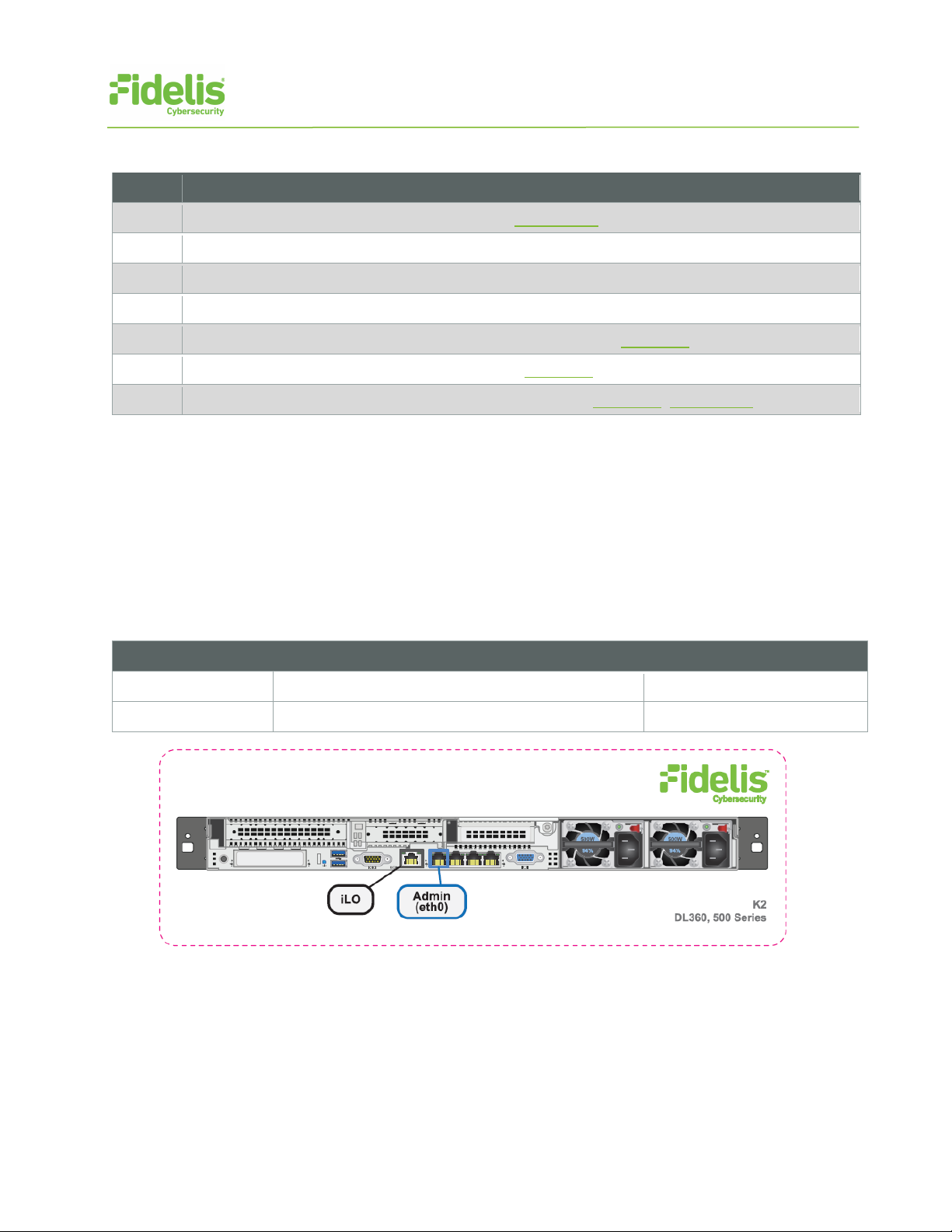
Figure 2: CommandPost/K2 Rear Port Assignments (Rev-I)
www.fidelissecurity.com ©Fidelis Cybersecurity
Page 4

QUICK START GUIDE
4
Appliance
Switch Port Type
Qty.
CommandPost/K2
Appliance
Switch Port Type
Qty.
CommandPost/K2
Hostname (FQDN)
CommandPost/K2-1.organization.net.
Subnet Mask
255.255.255.0
255.255.255.0
Fidelis Network® CommandPost/K2
4. CommandPost/K2 Networking Environment
The CommandPost/K2 appliances use the Admin network for service and inter-node communication.
CommandPost/K2 appliances offer the IPMI/iLO interface for optional out-of-band management of
the appliance.
Use the tables below to identify the count and type of switch ports necessary to support the number
of appliances for your deployment.
Admin Network
The Admin Network connects CommandPost/K2 to the Fidelis Network sensors, Collectors, and
Sandbox components.
GbE RJ45 (copper)
iLO / IPMI Network
Optional network for remote/out-of-band server administration.
GbE RJ45 (copper)
5. Appliance — Logical Network Configuration
Each physical connection must be assigned logical network information. Build a table of the logical
information for each appliance that you can reference during configuration. (See the sample table
below.) Appendix A
you will reference multiple times during setup.
Sample Network Configuration Table
Network Setting Assignments
Interface: Admin/eth0 iLO/IMM
Static IP Address 10.1.2.3 10.2.3.4
Gateway 10.1.2.1
Proxy Server 10.5.6.7
has a worksheet you can use to build your own Network Configuration table that
DNS Servers 8.8.4.4, 8.8.8.8
NTP Servers 0.pool1.ntp.org.
Time Zone UTC (+0)
www.fidelissecurity.com ©Fidelis Cybersecurity
Page 5

QUICK START GUIDE
5
− Via KVM Console: Connect a keyboard
Fidelis Network® CommandPost/K2
6. Appliance Installation
Rack Installation
Install each appliance in a location with necessary power and cooling.
Power
Connect power cables to the power supplies in the back of the appliance.
Network Cabling
Using the connectors and cables described in sections 3 and 4, begin to connect the appliances to
the networks.
To cable the CommandPost/K2 appliance(s) to the switches:
1. Connect Admin (eth0) port to the Admin switch port.
2. Connect the iLO port to the Admin (or iLO) switch port (optional).
7. Appliance Network Configuration
1. Power on the appliance(s).
2. Connect to the component CLI using one of the following methods:
and monitor to the appliance.
− For Fidelis Network appliances version
9.0.5 or later, the screen on the right is
displayed:
www.fidelissecurity.com ©Fidelis Cybersecurity
Page 6

QUICK START GUIDE
6
a. With Perform Initial Install or Factory Reset selected, press Enter.
b. Use the Up and Down arrow keys
Fidelis Network® CommandPost/K2
3. If you see the screen above, perform the following steps to apply the software. Otherwise
skip to step 4.
to select “CommandPost” or “K2+”,
and press Enter.
The system displays a screen with
the message “Congratulations, your
CentOS installation is complete.”
c. Press Reboot.
4. Login to the appliance through console or SSH.
Via SSH: Directly attach an Ethernet cable from a client system such as a laptop to the
Admin/eth0 port on the appliance. The default IP address is 192.168.42.11/24. Assign a
static IP from the same subnet to the network interface on the client system and connect to
the appliance using SSH.
5. Use these credentials at the login prompt:
− user: fidelis
− default password: fidelispass
6. From the command line, run:
sudo /FSS/bin/setup
You will be prompted for the SU (fidelis) password.
7. Within Setup, select Network Settings.
8. Configure the network parameters for the system and each active network interface.
− Use the Network Configuration table you prepared earlier.
− When complete, return to the top menu.
9. When complete, select OK to leave Setup.
10. From command line, reboot the system:
sudo /fss/bin/shutdown.pl --user admin --reboot
www.fidelissecurity.com ©Fidelis Cybersecurity
Page 7

QUICK START GUIDE
7
Fidelis Network® CommandPost/K2
8. Fidelis Licensing
The Fidelis Network CommandPost/K2 comes with a 60-day evaluation license. The
CommandPost/K2 user interface shows the Host ID for the Fidelis Network hardware, the current
license key, and the expiration date.
To access the License page:
1. Log into the CommandPost/K2.
2. Navigate to: System > Components.
3. Click the entry for the CommandPost/K2 (typically “Console”) to expand its details and
expose the Config button.
4. Click Config.
5. In the left navigation, select License.
If your license key shows <no license> or <invalid>, use the Request a License procedure below to
request a license.
Request a License
1. From the CommandPost/K2 License page, click Request License or click the Host ID to
start an email to license@fidelissecurity.com that includes the product type, serial number,
and Host ID.
2. Include in the body of the email:
− contact name and phone number
− organization name and site location
Fidelis Cybersecurity will respond within one business day with a license key.
Enter a License Key
After receiving a response to a license request:
1. Copy the license key exactly into the License Key box.
2. Click Save.
When complete, Fidelis CommandPost/K2 is operational and ready for additional Fidelis Network
components.
www.fidelissecurity.com ©Fidelis Cybersecurity
Page 8

QUICK START GUIDE
8
Network Setting
Assignments
Interface:
Admin/eth0
iLO/IMM
Static IP Address
Gateway
NTP Servers
K2
(Rev-I)
Form Factor
1U rack-mount chassis, SFF
Dual Intel Xeon Gold 6134
8-core 3.2 Ghz
128 GB
ECC DDR4 2666Mhz
3.6 TB HDD
6x HDD, RAID-5
Network Adapters (Default Config)
4x 1GbE
Out of Band Management
Integrated Lights Out Management (ILO)
Dual hot-swap
AC power supplies
H: 4.29 cm ( 1.69 in)
D: 70.7 cm (27.83 in)
Weight (appx.)
16.27 kg (35.85 lb)
10° to 35°C (50° to
95°F) at sea level
Fidelis Network® CommandPost/K2
Appendix A: Network Configuration Worksheet
CommandPost/K2
Hostname (FQDN)
Subnet Mask
Proxy Server
DNS Servers
Time Zone
Appendix B: System Specifications
CPU
Memory
Storage Capacity & Configuration
Power Supply
Dimensions
Operating Temperature
800W High Efficiency
W: 43.46 cm (17.11 in)
www.fidelissecurity.com ©Fidelis Cybersecurity
Page 9

QUICK START GUIDE
9
Appliance SKU with:
System Type
Fidelis Network® CommandPost/K2
Appendix C: System Types
For Fidelis Network Software version 9.0.5 and later, the table below shows the software to apply
based on the appliance SKU. You can find the SKU in the following locations:
(Note that the SKU typically starts with “FSS” or “FNH”.)
• Appliance lid UID decal (see sample on right)
• Shipping carton UID decal (see sample on right)
• Packing list
• Purchase Order
FSS-K2-I
FNH-K2-I
QSC_Fidelis_CP_Rev-I_20190509
CommandPost/K2
www.fidelissecurity.com ©Fidelis Cybersecurity
 Loading...