

Page 1

QUICK START GUIDE
Fidelis Network™ CommandPost+ Appliances
Rev-H
CommandPost (HP DL360-G9) Platforms
www.fidelissecurity.com
Page 2
QUICK START GUIDE
2
System
Account
Default Password
SSH / Appliance Console
fidelis
fidelispass
CommandPost GUI
ILO
administrator
(printed on label, top of server )
Fidelis Network™ CommandPost Appliances
1. System Overview
The Fidelis CommandPost+ appliance is the central component for command and control of Fidelis
Network components. With CommandPost+, you create and edit sensor policies, craft metadata
analytics and automation, and view alerts from connect ed sensor and Collector components.
Figure 1: Fidelis Network: CommandPost+ Appliance (Rev-H)
2. Documentation & References
Fidelis Network product documentation, applia nce specifications, and instructions can be found at
http://fidelisssecurity.com/customer-support/login
or through the icon in the CommandPost G UI.
Appliance Default Passwords
admin root
Technical Support
For all technical support r elat ed to this product, check w it h your site administrator t o det er m ine
support contract details. For support of your product , contact your reseller. If you have a direct
support contract with Fidelis Cybersecurity , contact the Fidelis Cybersecurity support team at:
• Phone: +1 301.652.7190
• Toll-free in the US: 1.800.652.4020 – Use the customer supp or t opt ion.
• Email: support@fidelissecurity.com
• Web: http://www.fidelissecurity.com/customer-support/login
www.fidelissecurity.com ©Fidelis Cybersecurity
Page 3
QUICK START GUIDE
3
Check
Fidelis Network Sensor – Appliance Requirements
Optical transceivers for s witches
Port Label
Physical Connect ion Ty pe (default)
Cable Type (minimum)
Admin
Fidelis Network™ CommandPost Appliances
CommandPost Setup Checklist
Appropriate rack space, power, and cooling (Appendix B)
Rack tools, rails, and connect or s
Keyboard and video monit or / KVM sw it ch for temporary appliance s etup
Power cables — two per a ppl iance, appropriate for pow er sour ce and region
Ethernet cables (cat5 and opt ical) for Admin and iLO ports (Section 3)
Network switches with enough physical ports (S ec t i on 4 )
Logical network infor matio n: I P addr esses, hostnames (Section 5, Appendix A)
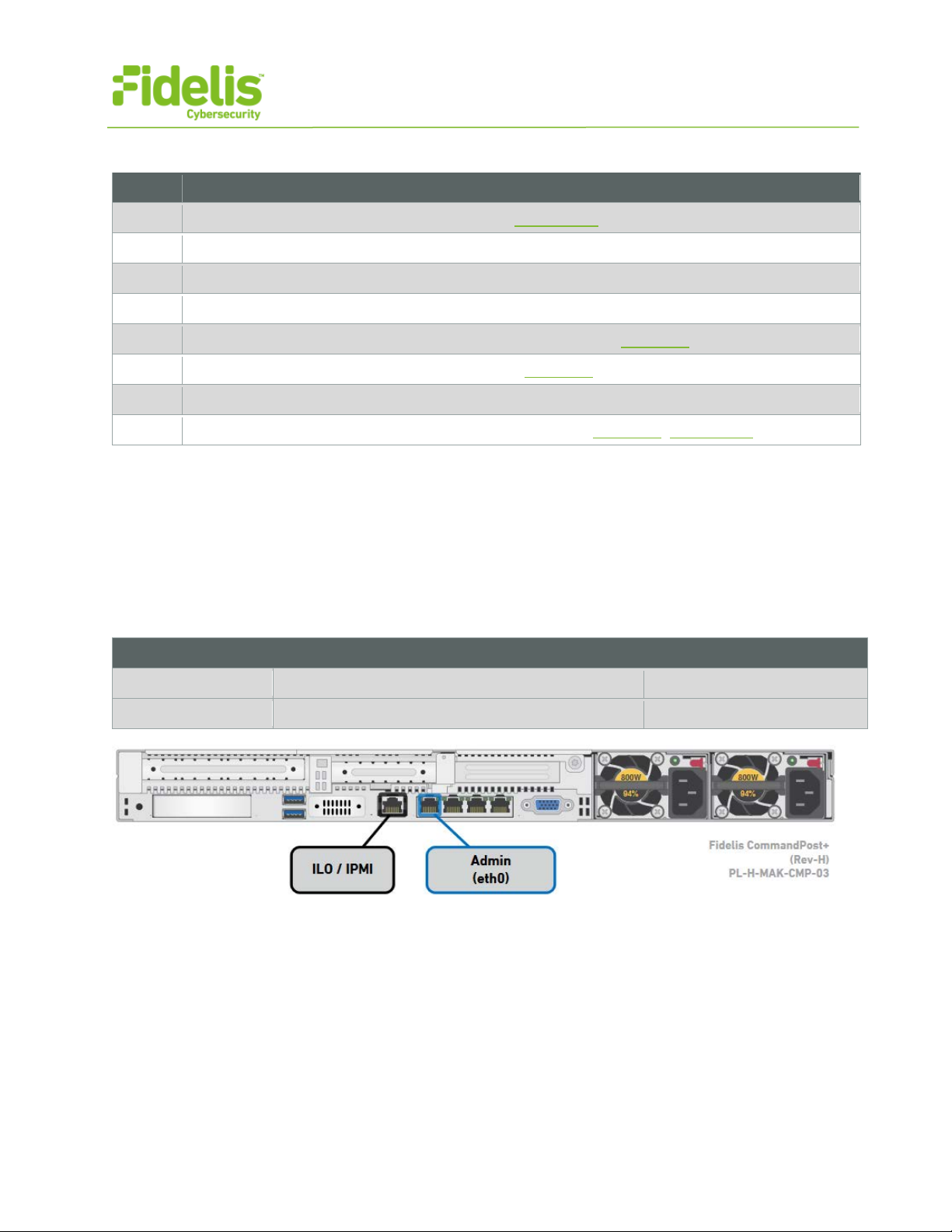
3. CommandPost: Network Port and Cabling Requirements
Each appliance must be connected to the various networks with appropriate cables and (in some
cases) transceivers). The t ables below describe the phy sical connection and cable t ype associated
with each port on the appliance.
CommandPost Appliance
GbE RJ45 (copper) Cat 5 patch cable
ILO GbE RJ45 (copper) Cat 5 patch cable
Figure 2: CommandPost+ Rear Port Assignments (Rev-H)
www.fidelissecurity.com ©Fidelis Cybersecurity
Page 4
QUICK START GUIDE
4
Appliance
Switch Port Type
Qty.
CommandPost+
Appliance
Switch Port Type
Qty.
CommandPost+
Network Setting
Assignments
Hostname (FQDN)
commandpost1.organization.net.
Fidelis Network™ CommandPost Appliances
4. CommandPost Networking Environment
The CommandPost+ appl iances use the Admin net w or k for ser vice and inter-node communication,
and offer the IPMI/ILO inter fac e f or opt ional out-of-band manage ment of the appliance.
Use the tables below to ident i fy the count and type of switch ports necessary to support the nu mber
of appliances for your dep loy m ent .
Admin Network
The Admin Network connects CommandPost to the Fidelis Network sensors, Collectors, and
Sandbox components.
GbE RJ45 (copper)
ILO / IPMI Network
Optional network for remo t e/out-of-band server adm inistration.
GbE RJ45 (copper)
5. Appliance — Logical Network Configuration
Each physical connectio n mu st be as signed logical networ k information. Build a table of the logical
information for each app lianc e (s ample below) that you can r eference during configuration. You will
reference this table multiple times during the clust er set up. Appendix A has a worksheet you may
use.
Sample Network Configuration Table
Interface: Admin/eth0 iLO/IMM
Static IP Address 10.1.2.3 10.2.3.4
Subnet Mask 255.255.255.0 255.255.255.0
Gateway 10.1.2.1
Proxy Server 10.5.6.7
DNS Servers 8.8.4.4, 8.8.8.8
NTP Servers 0.pool1.ntp.org.
Time Zone UTC (+0)
www.fidelissecurity.com ©Fidelis Cybersecurity
Page 5

QUICK START GUIDE
5
− Via SSH: Direct ly at tach an Ethernet
or later, the screen on the r ight is displayed:
Fidelis Network™ CommandPost Appliances
6. Appliance Installation
Rack Installation
Install each appliance in a n location with necessary pow er and cooling.
Power
Connect power cables to the pow er supplies in the back of the appliance.
Network Cabling
Using the connectors and cabl es described in sections 3 and 4, begin to connect the appliances to
the networks.
Cable the CommandPost+ appliance(s) to the switches:
1. Connect Admin (eth0) port to the ADMIN swit ch port.
2. Connect the iLO port to the ADMIN (or ILO) s w itc h port (optional).
7. Appliance Network Configuration
1. Power on the Appliance(s).
2. Connect to the componen t CLI using one of the following methods:
cable from a client system such as a
laptop to the Admin/eth0 por t on t he
appliance. The default IP addr ess is
192.168.42.11/24. Ass ign a s t at ic I P
from the same subnet to the net w ork
interface on the client system a nd
connect to the appliance u sing SSH.
− Via KVM Console: Connect a keyboard
and monitor to the appliance.
For Fidelis Network applia nces version 8.3.4
www.fidelissecurity.com ©Fidelis Cybersecurity
Page 6

QUICK START GUIDE
6
a. With [Perform Initial Inst al l or Factory Reset] selecte d, press Enter.
b. Use the Up and Down arrow keys to select
Fidelis Network™ CommandPost Appliances
3. If you see the screen above, perform the following steps t o apply the software. O t her wise
skip to step 4.
“CommandPost”, and pr ess Enter.
The system displays a screen w ith the
message “Congratulat ion s, your CentOS
installation is complete. ”
c. Press Reboot.
4. Use these credentials at t he login prompt:
− user: fidelis
− default password: fidelispass
5. From the command line, run: s udo /FSS/bin/s etup
You will be prompted for the S U (fidelis) password
6. Within Setup, select Network Settin gs.
7. Configure the network par am et er s for the system and each active network interface.
a. Use the Network Configur at ion t able you prepared earlier.
b. When complete, return to t he t op m enu.
8. When complete, select [O K] t o leave Setup.
9. From command line, reboot the system: sudo /fss/ bin/shutdown.pl --user admin --reboot
8. Fidelis Licensing — “Air Gap” and “No Feedback” Installations
If your Fidelis Network products are deployed with “Air G ap” or “ N o Feedback” licenses, you m ust
install the m with a license key. The CommandPost G UI shows the Host ID for the Fid el is N et w ork
hardware, the current license key, and the expiration date. To access the License page:
1. Log into the CommandPo s t .
2. Click System / Components / Console / Config.
3. Click the License tab.
If your license key shows <no li cense> or <invalid>. Refer to Request a License for more
information.
www.fidelissecurity.com ©Fidelis Cybersecurity
Page 7
QUICK START GUIDE
7
Network Setting
Assignments
Hostname (FQDN)
Gateway
DNS Servers
Time Zone
Fidelis Network™ CommandPost Appliances
Request a License
1. Click Request L icense or click the Host ID to st ar t an em ail to license@fidelissecurity.com
that includes the product t ype, serial number, and H ost ID.
2. Include in the body of the emai l:
− contact name and phone nu mber
− organization name and site location
Fidelis Cybersecurity w ill r espond within one business day with a license key.
Enter a License Key
After receiving a response t o a license request:
1. Copy the license key exact ly int o t he License Key box.
2. Click Save.
When complete, Fidelis CommandPost+ is operational and ready for additional Fidelis N et w or k
components.
Appendix A: Network Configuration Worksheet
CommandPost+
Interface: Admin/eth0 iLO/IMM
Static IP Address
Subnet Mask
Proxy Server
NTP Servers
www.fidelissecurity.com ©Fidelis Cybersecurity
Page 8

QUICK START GUIDE
8
CommandPost+
(Rev-H)
CommandPost+
(Rev-G)
Form Factor
1U rack-mount chassis, SFF
1U rack-mount chassis, SFF
Dual Intel Xeon v3
8-core 2.6 Ghz
2x Intel Xeon v2
6-core 2.6 Ghz
96 GB
ECC DDR4 2133Mhz
96 GB
ECC DDR3 1600Mhz
Storage Capacity &
Configuration
3 TB
6x HDD, RAID-5
3 TB
6x HDD, RAID-5
Network Adapters (Default
Config)
Integrated Management
Module II (IMM2)
Dual hot-swap
AC power supplies
Dual hot-swap
AC power supplies
H: 4.32 cm (1.7 in)
D: 69.85 cm (27.5 in)
W: 440 mm (17.3 in)
H: 43 mm (1.7 in)
Weight (appx.)
15.6 kg (35.5 lb)
15.6 kg (35.5 lb)
10° to 35°C (50° to
95°F) at sea level
5°C to 40°C (41°F to 104°F)
Altitude: 0 to 915 m (3,000 ft)
Fidelis Network™ CommandPost Appliances
Appendix B: System Specifications
CPU
Memory
4x 1Gb E 4x 1Gb E
Out of Band Management Integrated Lights Out Management (ILO)
Power Supply
Dimensions
Operating Temperature
800W High Efficiency
W: 43.47 cm (17.1 in)
QSC_Fidelis_CP_20170524
550W High Efficiency
D: 734 mm (28.9 in)
www.fidelissecurity.com ©Fidelis Cybersecurity
 Loading...