

Page 1

Spectra Users Guide
Introduction
1
1
Introduction
Congratulations on purchasing Spectra.
Spectra is an optimized de sign that combines functions of
computers and home entertainment f ac i lit ies . Sp ec tra aims
to provide individuals new and exciting ways to use their
PCs.
In the digital home, you may use your Spectra to connect to
the electronic enter tainm ent de vices and e njo y the f un and
convenience of combining different devices together. When
it comes to capturing, editing and sharing digital media,
Spectra is being o ptimi zed to m ake it easier to acc ess and
manipulate content and information when it is wanted,
where it is wanted.
Page 2

Spectra Users Guide
2
2 Introduction
Copyright
Copyright © FIC (First Inter national Com puter) Corporation
2004. All right reserved.
Disclaimer
FIC Corporation sh all not be liabl e for technical or editorial
errors or omissions contained herein; nor f or incidental or
consequential d amages resulting from using this material,
or the performance or use of this product.
FIC Corporation reserves the right to change product
specificatio ns without notice. I nformation in this document
may change without notic e.
No part of this document may be copied, reproduced, or
transmitted by any means, for any purpose without prior
written permission from FIC Corporation.
Trademarks
All tradem arks mentioned in th is m anual ar e the reg ister ed
property of their respective owners.
General Guideline
1. Read all of these instructions.
2. Save these instructions for future use.
3. Follow all warnings and instructions marked in the
computer.
4. Except as explaine d elsewhere in this m anual, do not
attempt to service the computer yourself. Opening or
removing covers that are marked “Do Not Remove”
could expose you to d anger ous voltage po ints or oth er
risks. Refer all servicing of marked components to
qualified personnel.
Page 3

Spectra Users Guide
Introduction
3
3
Restrictions
Installation Restrictions
1. Follow all warnings and ins t r uct ions m arked on
the product.
2. Unplug this product from the wall outlet before
cleaning. Do not use liquid cleaners or aerosol
cleaners. Use a damp cloth for cleaning.
3. Do not use this product near water, for example,
near a bathtub, washbowl, k itc hen sink or
laundry tub, in a wet basement or near a
swimming pool.
4. Do not place this product on an unstable cart,
stand, or table. The product could fall and
sustain serious damage.
5. Avoid using a telephone (other than a cordless
type) during an electrical storm. There may be a
remote risk of electric shock from lightning.
6. Do not use the telephone to report a gas leak in
the vicinity of the leak.
7. Slots and openings in the cabinet and the back
or bottom are provided for ventilation; to ensure
reliable operation of the product and to protect it
from overheating, these openings must not be
blocked or covered. The product should never
be placed near or over a radiator or heat register,
or in a built-in installat ion u nless pro per
ventilation is pro vided .
8. This product should be operated from the type of
power indicated on the marking label. If you are
not sure of the type of power available, consult
your dealer or local po wer company.
9. Do not allow anything to rest on the power cord.
Do not locate this product where persons will
tread on the cord.
Page 4

Spectra Users Guide
4
4 Introduction
10. If an extension cord is used with this product,
make sure that the total ampere rating of the
equipment plugged into the extension cord does
not exceed the extension cord ampere rating.
Also, make sure that the total rating of all
products plugged into the wall outlet does not
exceed the fuse rating.
11. Never push objects of any kind into this product
through cabinet slots as they may touch
dangerous voltage points or short out parts that
could result in a fire or electronic shock. Never
spill liquid of any kind on the product.
12. To reduce the risk of fire, use at least No. 26
AWG wire for the telecommunication line cord.
13. Always disconnect all telephone lines & all
power cords from the wall outlet before servicing
or disassembling this product.
14. Refer your system for servicing to qualified
service personal under the following conditions:
• When the power cord or plug is damaged or
frayed.
• If liquid has been spilled into the product.
• If the product has been exposed to rain or
water.
• If the product does not operate normally
when the operating instruct ions are follo wed.
Adjust only those controls that are covered
by the operating instructions, since improper
adjustment of other controls may result in
damage and will often require extensive
work by a qualified technician to restore the
product to normal condition.
• If the product has been dropped or the
cabinet has been damaged.
• If the product displays a distinct change in
performance, indicating a need for service.
Page 5

Spectra Users Guide
Introduction
5
5
Electrical Restrictions
This equipment is designed for connection to a
grounded (earthed) outlet. The grounding type
plug is an important safety feature. To reduce
the risk of electrical shock, damage to your
equipment, or loss of data, do not disable this
feature.
Thermal Restrictions
Do not cover the air intake and venting holes with
objects. Please operate the product in a well
ventilated ambient condition. If the system is to
be operated in an audio/visual cabinet, be sure
the cabinet is well ventilated on the front and/or
rear panel section otherwise heat generated by the
system will be accumulated in the cabinet.
Page 6

Spectra Users Guide
6
6 Introduction
Requirements
General Requirements
1. The requirements listed below are applicable to
all countries:
2. The length of the power cord set must be at least
6.0 feet (1.8 m) and a maximum of 14.76 feet
(4.5 m).
3. All power cord sets must be approved by an
acceptable accredited agency responsible for
evaluation in the country where the power cord
set will be used.
4. The power cord set must have a minimum
current capacity of 10A and a normal voltage
rating of 125 or 250 volts AC, as required by
each country’s power system.
5. The appliance coupler must meet the
mechanical configuration of an EN 60320. / IEC
320 Standard Sheet C13 connector, for mating
the appliance inlet on the computer.
Power Cord Set Requirements
The power cord set (appliance coupler, flexible cord, and
wall plug) you received with the computer meets the
requirements f or use in the country where you purchased
the equipment.
Power cord sets for use in other counties must meet the
requirements of the country where you use t he computer.
For more information on power cord set requirement,
contact your local authorized dealer, reseller, or service
provider.
Page 7

Spectra Users Guide
Introduction
7
7
Country-Specific Requirements
Power Cord Set Requirement
Country
Accredited
Agency
Applicable Note
Numbers
Australia EANSW 1
Austria OVE 1
Belgium CEBC 1
Canada CSA 2
Denmark DEMKO 1
Finland FIMKO 1
France UTE 1
Germany VDE 1
Italy IMQ 1
Japan JIS 3
The Netherlands KEMA 1
Norway NEMKO 1
Sweden SEMKO 1
Switzerland SEV 1
United Kingdom BSI 1
United States UL 2
Page 8

Spectra Users Guide
8
8 Introduction
1. Flexible cord must be <HAR> Type
HO5VV-F, 3-conductor. 1.0 mm2 conductor
size. Power cord set fittings (appliance
coupler and wall plug) must bear the
certification mark of the agency responsible
for evaluation in the country where it will be
used.
2. Flexible cord must be Type SVT or
equivalent. No. 18 AWG, 3-conductor. Wall
plug must be a two-pole grounding type with
a NEMA 5-15P (10A. 125V) or NEMA 6-15P
(15A 250V) configuration.
3. Appliance coupler, flexible cord, and wall
plug must bear a “PSE” mark and
registration number in accordance with the
Japanese DENAN Law. Flexible cord must
be Type VCT or VCTF, 3-conductor,
0.75mm2 conductor size. Wall plug must be a
two-pole grounding type with a Japanese
Industrial Standard C8303 (15A, 125V)
configuration.
Page 9

Spectra Users Guide
Introduction
9
9
I
I
I
n
n
n
s
s
s
t
t
t
a
a
a
l
l
l
l
l
l
a
a
a
t
t
t
i
i
i
o
o
o
n
n
n
I
I
I
n
n
n
s
s
s
t
t
t
r
r
r
u
u
u
c
c
c
t
t
t
i
i
i
o
o
o
n
n
n
s
s
s
(
(
(
f
f
f
o
o
o
r
r
r
p
p
p
o
o
o
w
w
w
e
e
e
r
r
r
s
s
s
u
u
u
p
p
p
p
p
p
l
l
l
y
y
y
)
)
)
1. English
CAUTION: DANGER OF EXPLOSIO N IF BATT ERY IS
INCORRECTLY REPLACED. REPLACE ONLY WITH SAME
OR EQUIVALENT TYPE RECOMMENDED BY T HE
MANUFACTURER. DIS CARD USED BATTERIES
ACCORDING TO THE MANUFACTURER'S
INSTRUCTIONS.
2. French
IL Y A DANGER D'EXPLO SION S'IL Y A REMPLACEMENT
INCORRECT DE LA BATTERIE . REMP LACER
UNIQUEMENT AVEC UNE BATTERIE DU MÊME TYPE OU
D'UN TYPE RECOMMANDÉ PAR LE CONSTRUCTEUR.
METTER AU RÉBUT LES BATTERIES USAGÉES
CONFORMÉMENT AUX INSTRUCTIONS DU FABRICANT.
3. German
VORSICHT ! Explisionsgefahr bei unsachgemäßen
Austausch der Batterie. Ersatz nur durch denselben oder
einem vom Hersteller empfohlenem ähnlichen Typ.
Entsorgung gebrauchter Batterien nach Angaben des
Herstellers.
4. Swedish
Explosionsfara vid felakti gt batteribyte.
Använd samma batterityp eller en ekvivalent typ som
rekommenderas av apparattillverkaren. K assera använt
batteri enligt fabrikantens inst ruktion.
5. Danish
Lithiumbatteri- Eksplosionsf are ved fejlagtig håndtering.
Udskiftning må kum ske med batteri af samme fabrikat og
type.
Lever det brugte batteri tilbage til leverandoren.
Page 10

Spectra Users Guide
110
0 Introduction
6. Norwegian
Ekspolsjonsafe ved feilakti g skift e av batt eri .
Benytt samme batteritype eller en tilsvarende type anbefal t
av apparatfabriknten.
Brukte batterier kasseres i henhold til fabrikantens
instruksjoner.
7. Finnish
Paristo voi räjähtää, jos se on virheellisesti asennettu.
Vaihda paristo ainostaan laitevalmistajan suosittelemaan
tyyppiin.
Hävitä käyteet paristo valmist aj an ohjeiden m ukaisesti.
1. The power supply can be operated at an ambient
temperature of 35 °C.
2. The power supply shall be installed according to
specification. The load current and output power
should not exceed the following specified
values.
3. INPUT : 100-127V ~ / 5A, 200-240V ~ / 2.5A AC,
47Hz-64Hz.
4. OUTPUT : +12V / 17A, -12V / 0.3A, +5V / 15A,
+5VSB / 2.5A, +3.3V / 16A, +12VSB /
2A(Optional)
5. MAX POWER : 250W
6. The power supply is a built-in component.
During installation into certain equipment, the
relevant requirements of EN 60950/IEC 60950,
UL 60950 and CSA C22.2 No. 60950-00 shall be
maintained.
7. The creep age distance, clearance, and
thickness of insulat ion in to c er tain pr imary and
ground as well as primary and secondary circuits
shall comply with the current requirements of EN
60950/IEC 60950, UL 60950 and CSA
60950-00.
Page 11

Spectra Users Guide
Introduction
111
1
8. This power supply must be connected to the
safety grounding before use.
B
B
B
a
a
a
t
t
t
t
t
t
e
e
e
r
r
r
y
y
y
(
(
(
l
l
l
i
i
i
t
t
t
h
h
h
i
i
i
u
u
u
m
m
m
)
)
)
The following caution statement is located in
the service and operating manual or on the
label adjacent to the battery.
Safety Instructions
The computer has been tested for conformance to
international safety regulations. Like any electronic device,
however, the computer should be used with care.
To avoid electrical shock, do not touch the modem card
when the system is in use. To protect yourself from
possible injury and to minimize the risk of damage to the
computer, read and follow these safety instructions:
FCC Statement
This device complies with part 15 of the FCC Rules.
Operation is subject to the following two conditions: (1) This
device may not cause harmful interference, and (2) this
device must accept any interference received, including
interference that may cause undesired operation.
FCC Caution: Any change or modifications not expressly
approved by the party responsible for compliance could
void the user’s authority to operate this equipment.
FCC Radiation Exposure statement
This equipment complies with FCC radiation
Page 12

Spectra Users Guide
112
2 Introduction
exposure limits set forth for an uncontrolled
environment. This equipment should be
installed and operated with minimum distance
2.5cm between the radiator & your body.
This transmitter must not be co-located or
operating in conjunction with any other
antenna or transmitter.
L
L
L
a
a
a
s
s
s
e
e
e
r
r
r
C
C
C
o
o
o
m
m
m
p
p
p
l
l
l
i
i
i
a
a
a
n
n
n
c
c
c
e
e
e
S
S
S
t
t
t
a
a
a
t
t
t
e
e
e
m
m
m
e
e
e
n
n
n
t
t
t
The CD-ROM / DVDRO M / CD-RW / DVD-RW dr ive in th is
computer is a laser product. The CD-ROM / DVD-ROM /
CD-RW / DVD-RW drive’s classification label (shown
below) is location on the dri ve.
Class 1 laser product
Caution: invisible laser radiation when open. Do
not stare into beam.
Caution: Use to any controls or adjustments or
procedures other than those specified herein may
result in hazardous radiate exposure. To prevent
exposure to laser emanations (Harmful to
Human eyes). Do not attempt disassemble this
unit
Page 13

Introduction
113
3
TableofContents
Introduction......................................................1
Copyright...........................................................................2
Disclaimer..........................................................................2
Trademarks .......................................................................2
General Guideline.
.
.
.
.
.
.
.
.
.
.
.
.
.
.
.
.
.
.
.
.
.
.
.
.
.
.
.
.
.
.
.
.
.
.
.
.
.
.
.
.
.
.
.
.
.
.
.
.
.
.
.
.
.
.
.
.
.
.
.
.
.
.
.
.
.
.
.
.
.
.
.
.
.
.
.
.
.
.
.
.
.
.
.
.
.
.
.
.
.
.
.
.
.
.
.
.
.
.
.
.
.
.
.
.
.
.
.
.
.
.
.
.
.
.
.
.
.
.
.
.
.
.
.
.
.
.
.
.
.
.
.
.
.
.
.
.
.
.
.
.
.
.
.
.
.
.
.
.
.
2
2
2
Restrictions.
.
.
.
.
.
.
.
.
.
.
.
.
.
.
.
.
.
.
.
.
.
.
.
.
.
.
.
.
.
.
.
.
.
.
.
.
.
.
.
.
.
.
.
.
.
.
.
.
.
.
.
.
.
.
.
.
.
.
.
.
.
.
.
.
.
.
.
.
.
.
.
.
.
.
.
.
.
.
.
.
.
.
.
.
.
.
.
.
.
.
.
.
.
.
.
.
.
.
.
.
.
.
.
.
.
.
.
.
.
.
.
.
.
.
.
.
.
.
.
.
.
.
.
.
.
.
.
.
.
.
.
.
.
.
.
.
.
.
.
.
.
.
.
.
.
.
.
.
.
.
.
.
.
.
.
.
.
.
.
.
.
.
.
.
.
.
.
.
.
.
.
.
.
.
.
.
.
.
.
3
3
3
Installation Restrictions .....................................................3
Electrical Restrictions........................................................5
Thermal Restrictions .........................................................5
Requirements.
.
.
.
.
.
.
.
.
.
.
.
.
.
.
.
.
.
.
.
.
.
.
.
.
.
.
.
.
.
.
.
.
.
.
.
.
.
.
.
.
.
.
.
.
.
.
.
.
.
.
.
.
.
.
.
.
.
.
.
.
.
.
.
.
.
.
.
.
.
.
.
.
.
.
.
.
.
.
.
.
.
.
.
.
.
.
.
.
.
.
.
.
.
.
.
.
.
.
.
.
.
.
.
.
.
.
.
.
.
.
.
.
.
.
.
.
.
.
.
.
.
.
.
.
.
.
.
.
.
.
.
.
.
.
.
.
.
.
.
.
.
.
.
.
.
.
.
.
.
.
.
.
.
.
.
.
.
.
.
.
.
.
.
.
.
.
.
.
.
.
6
6
6
General Requirements......................................................6
Power Cord Set Requirements..........................................6
Country-Specific Requirements.........................................7
Installation Instructions (for power supply).
.
.
.
.
.
.
.
.
.
.
.
.
.
.
.
.
.
.
.
.
.
.
.
9
9
9
Battery (lithium) ...............................................................11
Safety Instructions .
.
.
.
.
.
.
.
.
.
.
.
.
.
.
.
.
.
.
.
.
.
.
.
.
.
.
.
.
.
.
.
.
.
.
.
.
.
.
.
.
.
.
.
.
.
.
.
.
.
.
.
.
.
.
.
.
.
.
.
.
.
.
.
.
.
.
.
.
.
.
.
.
.
.
.
.
.
.
.
.
.
.
.
.
.
.
.
.
.
.
.
.
.
.
.
.
.
.
.
.
.
.
.
.
.
.
.
.
.
.
.
.
.
.
.
.
.
.
.
.
.
.
.
.
.
.
.
.
.
.
.
.
.
.
.
.
.
.
.
.
1
1
1
1
1
1
FCC Statement.
.
.
.
.
.
.
.
.
.
.
.
.
.
.
.
.
.
.
.
.
.
.
.
.
.
.
.
.
.
.
.
.
.
.
.
.
.
.
.
.
.
.
.
.
.
.
.
.
.
.
.
.
.
.
.
.
.
.
.
.
.
.
.
.
.
.
.
.
.
.
.
.
.
.
.
.
.
.
.
.
.
.
.
.
.
.
.
.
.
.
.
.
.
.
.
.
.
.
.
.
.
.
.
.
.
.
.
.
.
.
.
.
.
.
.
.
.
.
.
.
.
.
.
.
.
.
.
.
.
.
.
.
.
.
.
.
.
.
.
.
.
.
.
.
.
.
.
.
.
.
.
.
.
.
.
.
.
.
.
.
.
1
1
1
1
1
1
L
L
L
a
a
a
s
s
s
e
e
e
r
r
r
C
C
C
o
o
o
m
m
m
p
p
p
l
l
l
i
i
i
a
a
a
n
n
n
c
c
c
e
e
e
S
S
S
t
t
t
a
a
a
t
t
t
e
e
e
m
m
m
e
e
e
n
n
n
t
t
t
.
.
.
.
.
.
.
.
.
…
…
…
…
…
…
…
…
…
…
…
…
.
.
.
…
…
…
…
…
…
…
…
…
.
.
.
.
.
.
1
1
1
2
2
2
Table of Contents...........................................13
Getting Started...............................................15
Package Content.
.
.
.
.
.
.
.
.
.
.
.
.
.
.
.
.
.
.
.
.
.
.
.
.
.
.
.
.
.
.
.
.
.
.
.
.
.
.
.
.
.
.
.
.
.
.
.
.
.
.
.
.
.
.
.
.
.
.
.
.
.
.
.
.
.
.
.
.
.
.
.
.
.
.
.
.
.
.
.
.
.
.
.
.
.
.
.
.
.
.
.
.
.
.
.
.
.
.
.
.
.
.
.
.
.
.
.
.
.
.
.
.
.
.
.
.
.
.
.
.
.
.
.
.
.
.
.
.
.
.
.
.
.
.
.
.
.
.
.
.
.
.
.
.
.
.
.
.
.
1
1
1
5
5
5
Product Overview.
.
.
.
.
.
.
.
.
.
.
.
.
.
.
.
.
.
.
.
.
.
.
.
.
.
.
.
.
.
.
.
.
.
.
.
.
.
.
.
.
.
.
.
.
.
.
.
.
.
.
.
.
.
.
.
.
.
.
.
.
.
.
.
.
.
.
.
.
.
.
.
.
.
.
.
.
.
.
.
.
.
.
.
.
.
.
.
.
.
.
.
.
.
.
.
.
.
.
.
.
.
.
.
.
.
.
.
.
.
.
.
.
.
.
.
.
.
.
.
.
.
.
.
.
.
.
.
.
.
.
.
.
.
.
.
.
.
.
.
.
.
.
.
1
1
1
6
6
6
Front View
...................................................................16
Rear View
....................................................................16
Replacement Procedure................................17
Page 14

Spectra Users Guide
114
4 Troubleshooting
Before Replacement.
.
.
.
.
.
.
.
.
.
.
.
.
.
.
.
.
.
.
.
.
.
.
.
.
.
.
.
.
.
.
.
.
.
.
.
.
.
.
.
.
.
.
.
.
.
.
.
.
.
.
.
.
.
.
.
.
.
.
.
.
.
.
.
.
.
.
.
.
.
.
.
.
.
.
.
.
.
.
.
.
.
.
.
.
.
.
.
.
.
.
.
.
.
.
.
.
.
.
.
.
.
.
.
.
.
.
.
.
.
.
.
.
.
.
.
.
.
.
.
.
.
.
.
.
.
.
.
.
.
.
.
1
1
1
7
7
7
CPU.
.
.
.
.
.
.
.
.
.
.
.
.
.
.
.
.
.
.
.
.
.
.
.
.
.
.
.
.
.
.
.
.
.
.
.
.
.
.
.
.
.
.
.
.
.
.
.
.
.
.
.
.
.
.
.
.
.
.
.
.
.
.
.
.
.
.
.
.
.
.
.
.
.
.
.
.
.
.
.
.
.
.
.
.
.
.
.
.
.
.
.
.
.
.
.
.
.
.
.
.
.
.
.
.
.
.
.
.
.
.
.
.
.
.
.
.
.
.
.
.
.
.
.
.
.
.
.
.
.
.
.
.
.
.
.
.
.
.
.
.
.
.
.
.
.
.
.
.
.
.
.
.
.
.
.
.
.
.
.
.
.
.
.
.
.
.
.
.
.
.
.
.
.
.
.
.
.
.
.
.
.
.
.
.
.
.
.
.
.
.
.
.
.
.
.
.
.
.
.
.
.
.
.
.
.
.
.
.
.
.
.
.
1
1
1
8
8
8
RAM .
.
.
.
.
.
.
.
.
.
.
.
.
.
.
.
.
.
.
.
.
.
.
.
.
.
.
.
.
.
.
.
.
.
.
.
.
.
.
.
.
.
.
.
.
.
.
.
.
.
.
.
.
.
.
.
.
.
.
.
.
.
.
.
.
.
.
.
.
.
.
.
.
.
.
.
.
.
.
.
.
.
.
.
.
.
.
.
.
.
.
.
.
.
.
.
.
.
.
.
.
.
.
.
.
.
.
.
.
.
.
.
.
.
.
.
.
.
.
.
.
.
.
.
.
.
.
.
.
.
.
.
.
.
.
.
.
.
.
.
.
.
.
.
.
.
.
.
.
.
.
.
.
.
.
.
.
.
.
.
.
.
.
.
.
.
.
.
.
.
.
.
.
.
.
.
.
.
.
.
.
.
.
.
.
.
.
.
.
.
.
.
.
.
.
.
.
.
.
.
.
.
.
.
.
.
.
.
.
.
2
2
2
1
1
1
ODD.
.
.
.
.
.
.
.
.
.
.
.
.
.
.
.
.
.
.
.
.
.
.
.
.
.
.
.
.
.
.
.
.
.
.
.
.
.
.
.
.
.
.
.
.
.
.
.
.
.
.
.
.
.
.
.
.
.
.
.
.
.
.
.
.
.
.
.
.
.
.
.
.
.
.
.
.
.
.
.
.
.
.
.
.
.
.
.
.
.
.
.
.
.
.
.
.
.
.
.
.
.
.
.
.
.
.
.
.
.
.
.
.
.
.
.
.
.
.
.
.
.
.
.
.
.
.
.
.
.
.
.
.
.
.
.
.
.
.
.
.
.
.
.
.
.
.
.
.
.
.
.
.
.
.
.
.
.
.
.
.
.
.
.
.
.
.
.
.
.
.
.
.
.
.
.
.
.
.
.
.
.
.
.
.
.
.
.
.
.
.
.
.
.
.
.
.
.
.
.
.
.
.
.
.
.
.
.
.
.
.
.
.
2
2
2
2
2
2
HDD.
.
.
.
.
.
.
.
.
.
.
.
.
.
.
.
.
.
.
.
.
.
.
.
.
.
.
.
.
.
.
.
.
.
.
.
.
.
.
.
.
.
.
.
.
.
.
.
.
.
.
.
.
.
.
.
.
.
.
.
.
.
.
.
.
.
.
.
.
.
.
.
.
.
.
.
.
.
.
.
.
.
.
.
.
.
.
.
.
.
.
.
.
.
.
.
.
.
.
.
.
.
.
.
.
.
.
.
.
.
.
.
.
.
.
.
.
.
.
.
.
.
.
.
.
.
.
.
.
.
.
.
.
.
.
.
.
.
.
.
.
.
.
.
.
.
.
.
.
.
.
.
.
.
.
.
.
.
.
.
.
.
.
.
.
.
.
.
.
.
.
.
.
.
.
.
.
.
.
.
.
.
.
.
.
.
.
.
.
.
.
.
.
.
.
.
.
.
.
.
.
.
.
.
.
.
.
.
.
.
.
.
.
2
2
2
5
5
5
PCI Express.
.
.
.
.
.
.
.
.
.
.
.
.
.
.
.
.
.
.
.
.
.
.
.
.
.
.
.
.
.
.
.
.
.
.
.
.
.
.
.
.
.
.
.
.
.
.
.
.
.
.
.
.
.
.
.
.
.
.
.
.
.
.
.
.
.
.
.
.
.
.
.
.
.
.
.
.
.
.
.
.
.
.
.
.
.
.
.
.
.
.
.
.
.
.
.
.
.
.
.
.
.
.
.
.
.
.
.
.
.
.
.
.
.
.
.
.
.
.
.
.
.
.
.
.
.
.
.
.
.
.
.
.
.
.
.
.
.
.
.
.
.
.
.
.
.
.
.
.
.
.
.
.
.
.
.
.
.
.
.
.
.
.
.
.
.
.
.
.
.
.
.
.
.
2
2
2
7
7
7
Troubleshooting.............................................29
Power Problems.
.
.
.
.
.
.
.
.
.
.
.
.
.
.
.
.
.
.
.
.
.
.
.
.
.
.
.
.
.
.
.
.
.
.
.
.
.
.
.
.
.
.
.
.
.
.
.
.
.
.
.
.
.
.
.
.
.
.
.
.
.
.
.
.
.
.
.
.
.
.
.
.
.
.
.
.
.
.
.
.
.
.
.
.
.
.
.
.
.
.
.
.
.
.
.
.
.
.
.
.
.
.
.
.
.
.
.
.
.
.
.
.
.
.
.
.
.
.
.
.
.
.
.
.
.
.
.
.
.
.
.
.
.
.
.
.
.
.
.
.
.
.
.
.
.
.
.
.
.
.
.
.
3
3
3
0
0
0
Hard Disk Problems.
.
.
.
.
.
.
.
.
.
.
.
.
.
.
.
.
.
.
.
.
.
.
.
.
.
.
.
.
.
.
.
.
.
.
.
.
.
.
.
.
.
.
.
.
.
.
.
.
.
.
.
.
.
.
.
.
.
.
.
.
.
.
.
.
.
.
.
.
.
.
.
.
.
.
.
.
.
.
.
.
.
.
.
.
.
.
.
.
.
.
.
.
.
.
.
.
.
.
.
.
.
.
.
.
.
.
.
.
.
.
.
.
.
.
.
.
.
.
.
.
.
.
.
.
.
.
.
.
.
.
.
.
.
.
3
3
3
0
0
0
Specifications ................................................31
System Hardware.
.
.
.
.
.
.
.
.
.
.
.
.
.
.
.
.
.
.
.
.
.
.
.
.
.
.
.
.
.
.
.
.
.
.
.
.
.
.
.
.
.
.
.
.
.
.
.
.
.
.
.
.
.
.
.
.
.
.
.
.
.
.
.
.
.
.
.
.
.
.
.
.
.
.
.
.
.
.
.
.
.
.
.
.
.
.
.
.
.
.
.
.
.
.
.
.
.
.
.
.
.
.
.
.
.
.
.
.
.
.
.
.
.
.
.
.
.
.
.
.
.
.
.
.
.
.
.
.
.
.
.
.
.
.
.
.
.
.
.
.
.
.
.
.
.
.
3
3
3
1
1
1
Motherboard....................................................................31
Peripheral Cards .............................................................31
Spinning Media................................................................32
Chassis............................................................................32
Thermal/Acoustic Solution...............................................33
Power Supply ..................................................................33
Controller Board ..............................................................33
RF Keyboard & Mouse Board .........................................33
Front Panel I/O Board .....................................................34
RCA Connector Board.....................................................34
External Peripherals (if applicable) .................................34
System Software.
.
.
.
.
.
.
.
.
.
.
.
.
.
.
.
.
.
.
.
.
.
.
.
.
.
.
.
.
.
.
.
.
.
.
.
.
.
.
.
.
.
.
.
.
.
.
.
.
.
.
.
.
.
.
.
.
.
.
.
.
.
.
.
.
.
.
.
.
.
.
.
.
.
.
.
.
.
.
.
.
.
.
.
.
.
.
.
.
.
.
.
.
.
.
.
.
.
.
.
.
.
.
.
.
.
.
.
.
.
.
.
.
.
.
.
.
.
.
.
.
.
.
.
.
.
.
.
.
.
.
.
.
.
.
.
.
.
.
.
.
.
.
.
.
.
.
.
.
.
3
3
3
5
5
5
Operating System ............................................................35
Software Packages .........................................................35
BIOS................................................................................35
Page 15

Spectra Users Guide
Troubleshooting
115
5
Chapter 1
GettingStarted
Package Content
1. Spectra System
2. RF Keyboard and Mouse
3. Remote Control
4. Power Cord
5. SATA Cable
6. ODD IDE Cable
7. Driver CD
8. Addendum
9. User's manual
10. Battery *6
Page 16
Spectra Users Guide
116
6 Troubleshooting
Product Overview
Front View
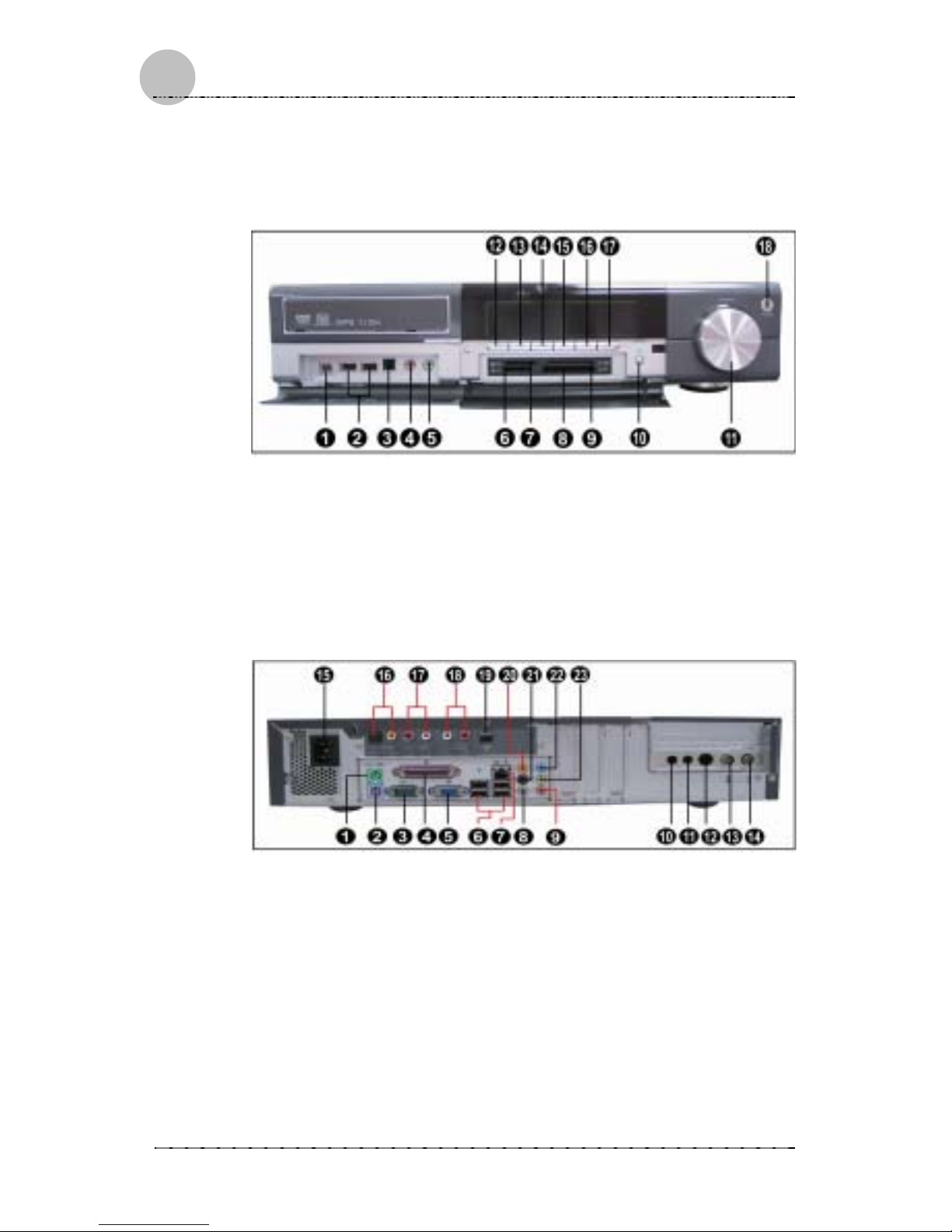
1 IEEE 1394 (4 PIN) 7 SD & MMC 13 Play
2 USB Port 8 CF 14 Pause
3 SPDIF IN (Optical) 9 SMC 15 REW
4 MIC IN 10 RF Connect 16 FWD
5 LINE OUT 11 Volume Control 17 REC
6 MS 12 Stop 18 Power Switch
Rear View
1 Mouse 13 TV (Cable)
2 Keyboard 14 FM
3 COM Port 15 Power Socket
4 Parallel Port 16 SPDIF Out (Optical)
5 VGA 17 Line OUT(White/Left, Red/Right)
6 USB Port 18 Line IN(White/Left, Red/Right)
7 RJ45 LAN Connector 19 IEEE1394 (6 Pin)
8 Side Speaker Out 20 Rear Speaker Out
9 MIC IN 21 Center/Subwoofer
10 Audio In (R) (Optional) 22 Line In
11 Audio In (L) (Optional ) 23 Front Speaker Out
12 S-Video (Optional)
Page 17

Spectra Users Guide
Troubleshooting
117
7
CChhaapptteerr 22
Replacement
Procedure
Before Replacement
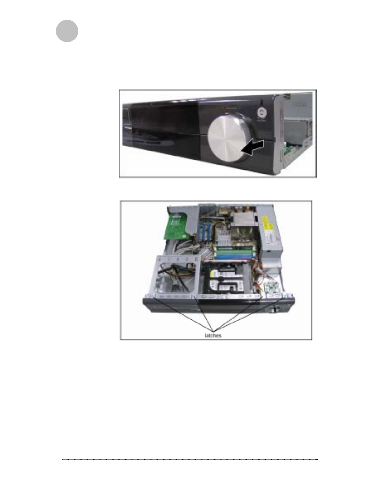
1. Unscrew three nails on the rear side of the case.
2. Remove the cover of the case by push in the direction
indication in the picture bel o w.
Page 18

Spectra Users Guide
118
8 Troubleshooting
3. After the cover is removed, the arrangement of the
system is shown as below. Unscrew two nails on the
linking bar, and separate the linking bar from the
system (Please see the enlarged picture below.)
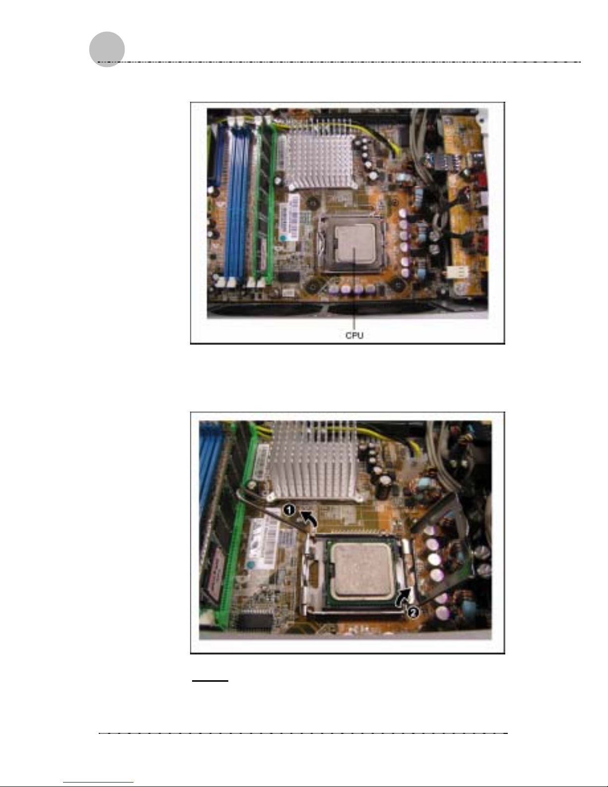
CPU
1. Release four nails on the four corners of the heat sink
Page 19
Spectra Users Guide
Troubleshooting
119
9
2. Lift up the heat sink and you see the CPU.
3. To replace the CPU, first lift up the side metal by
pressing down a little bit (1). And then lift up the metal
bracket (2).
Note:
When you replace the CPU, please aim at the four angles
and put it down.
Page 20

Spectra Users Guide
220
0 Troubleshooting
4. Fasten the four nails on the heat sink.
Note:
In a diagonal direction, fasten two nails at a time. It is
suggested gently slide in the nails first, a nd fasten them
securely later.
5. Use the air-flow guide coming in the package. Slide it
in along the two metal pieces on the two sides (1) and
then secure it by using the sticker on the air-flow
guide (2).
Page 21

Spectra Users Guide
Troubleshooting
221
1
RAM
1. To replace RAM, just slide into the slot.
Page 22
Spectra Users Guide
222
2 Troubleshooting
ODD
1. Remove the volume control button.
2. Loosen the panel from four latches.
Page 23

Spectra Users Guide
Troubleshooting
223
3
3. Remove two wires: RF control board cable and IR
receiver cable. And then remove the front panel of the
system.
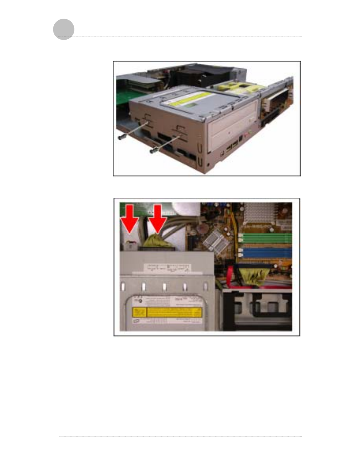
4. Slide in the ODD.
Page 24
Spectra Users Guide
224
4 Troubleshooting
5. Fasten two nails to secure the ODD.
6. Connect ODD cable and power cable.
Page 25

Spectra Users Guide
Troubleshooting
225
5
HDD
1. Slide the HDD into the HDD holder.
Note:
Before you slide the HDD into the holder, make sure you
focus the four jacks on the side of the HDD.
Page 26

Spectra Users Guide
226
6 Troubleshooting
2. Connect the power and Serial ATA cable.
Note:
There will be labels on the HDD to g uid e you to slide in
the HDD into the holder.
Serial ATA cable is the accessory coming in the package.
Page 27

Spectra Users Guide
Troubleshooting
227
7
PCI Express
1. Unscrew one nail on the bracket.
2. Remove the bracket. Unscrew the nail on the slot, and
insert the card on the riser card.
Page 28

Spectra Users Guide
228
8 Troubleshooting
3. After replacement, slide the bracket back to the system
and fasten it with a nail.
When you put the metal slot back, make sure the slot
slide into the latch.
Page 29

Spectra Users Guide
Troubleshooting
229
9
AAppppeennddiixx AA
Troubleshooting
Your system has passed a series of rigorous quality
assurance tests to guarantee reliable performance.
However, the s ystem is a complicated piece of equipm ent
and as such m a y malf unc tion if used incorrectly or if one of
its components fails. This appe ndix attempts to anticipate
potential problem s that m ay crop up dur ing the use of your
computer. Included ar e important tips and inform ation you
will need to help locate and solve problems you encounter.
In general, troubleshooting involves an organized approach
to problem solving. You should always try to isolate the
problem and identify the defective device (hardware) or
improper setting (software). When you encounter a
problem, the first thing you should do is perform a thorough
visual inspect ion of the system . If no indicators are lit and
you cannot hear the f an, then the c om puter is pr obab ly not
receiving power. Make sure the power cord is plugged in. If
you are using a power s trip or surge pr otector, e nsure that
those devices are turned on.
A problem can be caused by an improperly connected
cable. Ensure that n one of the connect ors ’ p ins are bent or
broken. Check all cables connected to your computer. If
any are cut, f rayed or damaged i n any way, replace t hem
right away. N ev er us e a d a maged cable. A dam aged cable
is not only a f ire hazard, it may also c ause a short circuit,
resulting in irreparable damage to your computer.
The examples that follow provide useful tips and
information th at wil l help you is olat e and solve som e of th e
more common problems you may encounter. If the problem
persists after trying the suggested solutions, contact your
dealer or a qualified service technician.
Page 30

Spectra Users Guide
330
0 Troubleshooting
Power Problems
Q: The system won’t turn on.
L The computer may not be properly connected to a
grounded wall outlet. Make sure the power cord is
firmly plugged into the wall outlet and into the
computer.
L The wall outlet may not be working. To check, plug
another device (s uch as a lam p) into the wall outlet. If
the outlet is not working, use another wall outlet.
L If the computer was shut down by a sudden power
failure, the user cannot use the power button to restart
immediately. To turn the computer back on, first
unplug the power cor d and wait about 10 sec onds for
complete discharge before plugging the power cord
back in. Then press the power button.
Hard Disk Problems
Q: The hard disk drive seems to be
operating slowly
L The files stored on your har d disk may be fragmented.
Check for lost allocation units by running Disk
Defragmenter. For more information, refer to the
Windows Help. T o open W indows He lp, clic k the Start
button, and then click Help and Support
Page 31

3311
Specifications
AAppppeennddiixx BB
Specifications
System Hardware
Motherboard
a) Form Factor and size
uATX 9.6" x 9.6"
b) Processors supported
Intel LGA775 Prescott processor
c) Processor Socket
LGA 775
d) Chipset
Intel 915G / ICH6(default)
e) Memory sockets (type and
quantity)
DDR 333/400 DIMM x 4
f) PCI Express slots
x16 PCIe * 1
g) PCI Slots
3 (for 2x Low Profile / 2x Standand
through Riser)
h) Serial ATA ports
4
i) Parallel ATA channels
2
j) Audio
High Definition 7.1 Channel (ALC880)
j) I/O Chip
ITE-8712HX
k) USB ports supported
8 (Stand by power support under S3)
l) Additional internal headers
Front USB*2/Front Audio/IrDA/Powe
r
LED/HDD LED/ACPI Power
Button/Control board/headers.
m) Rear Panel I/O connectors
Audio Jacks x5 / Mic-in x1 / RJ45 x1 /
USB x4/ Serial port x1 / PS2 x2 /
Parallel port x1
Peripheral Cards
a) Graphics
x16 PCI Express / DVI / D-Sub (through
DVI to D-Sub connector) / S-video /
Composite (through S-video to
Composite cable)
b) DVI Card (ADD2)
x16 PCI Express / DVI / D-Sub (through
DVI to D-Sub connector) /
c) TV Tuner
Analog TV Tuner Card+PVR (Digital
Optional) / NTSC, PAL, SECAM, ATSC,
DVB-T, DVB-C, DVB-S (depends on
tuner)
d) Wireless LAN
Caswell Wireless LAN Card / 802.11
Page 32

Spectra Users Guide
332
2 Troubleshooting
b/g (PCI) /
e) LAN
On board / 10/100 Support
f) Riser Card
i) PCI portsx2
Spinning Media
a) Hard Disk Drive
i) Physical Size
Standard 3.5" HDD
ii) Capacity (Gb)
120GB or higher
iii) Bus
SATA
iv) Rotating Speed
7200rpm
v) Cache Size
2MB / 8MB
vi) UDMA Modes
UDMA modes 0-5+/PIO modes 0-4
vii) Average r/w seek
<8.5 ms
b) Optical Disk Drive
DVD Dual/Multi
i) Physical Size
5.25"
ii) Bus
ATAPI Compatible
iii) Write Speed
DVD4x4x2/24x16(DVD Dual)
iv) Read S pee d
DVD12x/32x
v) Read Modes/Media
DVD±R/+RW/-RW,CD-RW/-R
vi) Buffer Size
2MB
vii) UDMA Modes
0-2+/PIO modes 0-4
c) Floppy Disk Drive (if
applicable)
8 in 1 card reader
i) Physical Size
slim-type
ii) Capacity
SD/MMC/CF(Type I/II)/SMC/MS/MS
Pro/Micro Drive
Chassis
a) Form Factor
Advanced Form Factor: 86(H) x 430(W)
x 390(D)mm
c) Peripheral Card Support
1x LP x16 PCIe / 2x full height & half
length PCI
d) Antennas
1x external wireless antenna (Default)
or 2x internal wireless antenna for
802.11 b/g (Optional)
e) External 5.25” Bays
1
f) External 3.5” Bays
N/A
g) Internal 5.25” Bays
N/A
h) Internal 3.5” Bays
2
Page 33

Spectra Users Guide
Troubleshooting
333
3
i) Power Supply form factor
Proprietary
82mm(H)x265mm(W)x68mm(D)
j) Front Panel I/O support
2xUSB / 1x microphone / 1x
headphone/ 1x SPDIF-in / 1X
IEEE1394
l) Material (Chassis and
Bezel)
SECC/ABS
m) Bezel LED indicators
Dual color power LED (Green and
Amber) / Blue Knob LED/ HDD status
on Blue LED Display
Thermal/Acoustic Solution
a) PSU fan
x2 (80mm x 80mm x 15mm axial fan)
b) Processor Heatsink
c) Fan Speed Control
Power Supply
250W/with Fan Control
Controller Board
a) USB Controller
Cypress AN2131
b) USB Hub
Cypress CY7C65640_LFC
c) Micro Controller
Microchip PIC 18F4320-I/TP
d) IR receiver
PDI USB D2
e) LED Display Module
TOSD-5711BB 120*25*12 mm (Taiwan
Oasis)
f) ACPI Power Button
YES
g) Stand-by / Resume Button
YES
h) Power LED
Green for On/ Amber for Stand-by
i) RF Reset button
YES
j) Transport buttons
Play/Pause/Stop/Fast
Forward/Rewind/Record
k) Volume Knob Encoder
Panasonics GS Encoder
l) Knob LED
Blue * 8
m) Frimware
Weikeng
RF Keyboard & Mouse Board
a) Interface
USB 1.1
b) Antenna
Yes
Page 34

Spectra Users Guide
334
4 Troubleshooting
d) Manufacturer
Chicony
Front Panel I/O Board
a) USB Ports
USB2.0*2
b) Audio ports
Mic-in*1/Headset*1/SPDIF-In
c) IEEE1394 Port
Firewire*1 (4Pin)
RCA Connector Board
a) SPDIF-out
Coax and Optical
b) SPDIF-in
Coax and Optical (Layout Only)
c) Stereo
Stereo Line-in (L/R)/Stereo Line-out
(L/R)
d) IEEE1394
Firewire*1 (6Pin)
External Peripherals (if applicable)
b) Remote
FIC define
c) Keyboard
YES / 27 Mhz RF/Multimedia
d) Mouse
YES / 27 Mhz RF/ Wheel/optical
Page 35

Spectra Users Guide
Troubleshooting
335
5
System Software
Operating System
Windows XP 2005 Media Center Edition ONLY (Symphony)
Software Packages
Microsoft Window XP Service Packs
Features The feature set needed for
(1) TV(thru TV tuner)
(2) DVD playback
(3) CD burning
(4) media editing
(5) media playback (including video, audio, and digital
photo manipulation).ex)PVR application
(7) DVD burning / authoring software
BIOS
Award
Features Full keyboard/mouse functionality in the BIOS setup
utility; Quick boot power on self test (minimal POST, 5
seconds from S3); SATA support; hot plug support;
legacy USB support; ACPI support; Fan control support;
 Loading...