

Page 1

Chapter
Outline of the MD02
1.1 Introduction
This chapter provides the outline features and operation of the MD02 including the BIOS
Setup program and other system options.
The MD02 notebook offers the latest in advanced portable computing and multimedia
technology that even outperforms most desktop computers. It incorporates the latest Intel
Dothan Processor and fully compatibles with an entire library of PC software based on
operating systems such as MS-DOS, Windows 2000 / XP. It also runs on future versions of
Windows. It comes with a built-in keyboard, glide pad pointing device, sound system,
PCMCIA slots, USB (Universal Serial Bus) port, IEEE 1394 port, advanced power
management and more new multimedia features.
1.2 Feature Highlights
The MD02 includes a variety of innovative features:
Category
CPU Intel Dothan 1.8 GHZ
Core Logic Intel Montara-GM+ (North Bridge) :
Cache
Memory
System
Memory
CPU(Banias) I/F
VGA Controller
LVDS I/F
DVOB&DVOC IF.
RGB analog I/F
200/266 DDR MEMORY I/F
Hub-Link I/F
Intel ICH4-M (South Bridge) :
Integrated Hub-Link I/F to connect with PCI Bridge
Dual IDE Master/Slave Controller ,Integrated DMA
Controller
1.1/2.0 Universal Serial Bus Host Controller
Integrated 10/100M Fast Ethernet MAC Controller
Integrated Audio Controller with AC97 V2.2 Interface
Advanced Power Management(ACPI)
RTC
Integrated PCI to LPC Bridge
Integrated Audio Controller with AC97 Interface
PCI Bus Interface (PCI 2.2 compliant)
GPIO
Advance PIC
L1 Cache (Pentium Processor internal):
32KB code and 32KB data
L2 Cache (Pentium Processor internal):
1MB Advanced Transfer Cache,8 way associativity
64-byte line size
Expansion Memory: 2 SO-DIMM Slot (1.25”)
Size: 128/256/512MB/1G
Specification Steppi
ng
FIC MD02 Service Manual 1-1
PDF created with FinePrint pdfFactory trial version http://www.fineprint.com
Page 2

r I/F
Outline of the MD02
Type: DDR DRAM, 3.3V
Data Path: 64Bit
Frequency : 266/200MHz
Please refer to the MD02 Key component list in detail.
BIOS ROM Flash ROM
1st Vendor : SST 49LF004A TSSOP Package 4Mbit LPC flash
ROM
2nd Vendor : <TBD>
4Mbit, 32 pin TSSOP package
PS: PLCC32 Package is just for DEBUG
Super I/O None
RTC +
NVRAM
K/B
Controller
PMU New PMU08
VGA
Controller
VRAM Share system memory, UMA (using DVMT configuration)
TV out
encoder
CardBus
Controller
Sound
Modem Ambit MDC modem
On board
LAN
802.11b Support by Intel Calexico Mini-PCI Wireless LAN Card
1394 TI PCI4510, support one port
Cellular I/F Support PDC/PIAFS/CdmaOne/Dupa(None) Suppo
Integrated in South Bridge (Intel ICH4-M)
Real Time Clock with 256 byte extended CMOS.
IBM AT Clock/Calendar/Alarm (14 Bytes)
Mitsubishi M38857M8 LPC KBC
Internal K/B, Touch Pad, External K/B or M/S
Supported A20Gate,firmware version 2.14
Mitsubishi M38859FFHP
Embedded Controller
Embedded in Intel Montara-GM+
High Performance and high quality 3D accelerator
Integrated dual DVO bridge
Integrated LVDS Interface
Integrated RGB analog Interface
High performance 2D accelerator
Complete TV-OUT/Digital Flat Panel Solution
None
TI PCI4510 (PCI Card Bus controller)
PC/Card Bus Type II x1
Build in smart card (none)
AC’97 CODEC
Realtek ALC202
AC’97 Revision 2.2 Compliant
V.90, K56flex, ITU-T V.34, V.32, RJ11 Jack
TIA/EIA 602, V.42
ITU-T V.17, V.29, V.27ter, V.21 Ch2
TIA/EIA 578 Class1 FAX
Wake up on Ring
Intel ICH4-M + BroadCom BCM 4401
Support LAN boot
Support for auto-negotiation (10BASE-T and 100BASE-TX)
Wake up On LAN
<Design Ready Only>
TBD
rt by
Cellula
1-2 FIC MD02 Service Manual
PDF created with FinePrint pdfFactory trial version http://www.fineprint.com
Page 3

Outline of the MD02
USB
Intel ICH4-M
IDE Interface
(Intel ICH4M)
Printer
Interface
Serial
Interface
External
PS/2 Port
(M38859)
Universal
Serial Bus
(Intel ICH4M)
Infrared None
Modem 56K Data/Fax Modem (v.90)
LAN 10/100 Base TX LAN
LCD Panel 14.1” XGA
HDD 2.5 inch HDD (Standard)
CD-ROM
(Option)
FDD(None) USB FDD
DVD
(Option)
CDRW,Combo
Pointing
Device
Keyboard Internal Keyboard
Integrated in South Bridge Intel ICH4-M)
USB v.1.1 and Intel Universal HCI v.1.1 compatible
USB v.2.0 and Enhance Universal HCI v.2.0 compatible
Eighteen level (doublewords) data FIFO with full scatter and
gather capability
Root hub and four function ports
Integrated physical layer transceivers with optional over-current
detection status on USB inputs
Fast IDE, 2 ports:
--Integrated multithreaded I/O link mastering with read pipelined
streaming
--Dual independent IDE channel each with 16 DW FIFO
--Native and compatibility mode
--PIO mode 0,1,2,3,4, and multiword DMA mode 0,1,2
--Ultra DMA 33/66/100
None
None
External Keyboard or PS/2 Mouse
Exclusively connected.
Can use both device by using branch cable(option)
--Integrated multithreaded IO link mastering
--Dual independent OHCI controllers with root hub
--Support up to 6 USB ports
--Support legacy devices
--Over current detection equipped
--Option to separately configure each port as a wake-up source
Lan boot support
14.1” SXGA+
; Please refer to the MD02 Key component list in detail.
9.5mm Height
; Please refer to the MD02 Key component list in detail.
CD-ROM (9.5mm Height)
; Please refer to the MD02 Key component list in detail.
3 mode Support
; Please refer to the MD02 Key component list in detail.
DVD
9.5mm Height ,8X
; Please refer to the MD02 Key component list in detail.
9.5mm Height ,24X
; Please refer to the MD02 Key component list in detail.
Internal Touch Pad
Pad SYNAPTICS : TM41P-351
Please refer to the MD02 Key component list in detail.
6.5mm Height, 3.0mm Stroke, 19mm Pitch
USB
Cable
.
FIC MD02 Service Manual 1-3
PDF created with FinePrint pdfFactory trial version http://www.fineprint.com
Page 4

Outline of the MD02
Vendor: ALLTOP
PAN-international
; Please refer to the MD02 Key component list in detail.
Speakers
(audio)
Microphone Built-in non-directional Back Electric Condenser Microphone
Buzzer Not support
Battery Battery Pack
RTC Battery Ni-MH Battery
DC/DC
Converter
CPU Vcore 0.7~1.708V Max 25A
AC Adapter PA-1600-05 : Delta
Two built-in dynamic speakers
40 x 20mm, 1W 4Ω
Panasonic : WM62PCX
Type: 8 cell Li-ION Battery with EEPROM
Voltage: 14.4V
Cell: 1800mAh Prisamtic
Method: 4P2S
Capacity: 3600mAh/52Wh Panasonic
Vendor: SANYO/ Panasonic
; Please refer to the MD02 Key component list in detail.
Model: 3/V 15H
Voltage: 3.6V
Capacity: 15mAh
Vendor: VARTA
Daughter board
5.0 V Max 7.0 A
3.3 V Max 4.5 A
1.5V Max 2A
1.8V Max1A
Input: AC100 – 240V, 50/60Hz
Output: 19V, 60W Peak 80W
Size: 110mm x 50mm x 29mm (Delta)
Vendor: Delta
Color : TBD
; Please refer to the MD02 Key component list in detail.
Size 310
Weight A
MM X
UPPORTS KENSINGTON LOCK
S
ROUND
HDD, FDD, CD-ROM
MM X
266
2.54 K
MM
27.3
G OR
(H)
LBS WITH
4.5
AND ONE LI-ION BATTERY PACK
14.1” LCD S
YSTEM WITH
1-4 FIC MD02 Service Manual
PDF created with FinePrint pdfFactory trial version http://www.fineprint.com
Page 5

Battery Handling
Category Specification Remark
Outline of the MD02
Battery Charging
Max Change
Current:
1.7A-1.75A
150mA
Battery Life 1st Li-ion 4.5 h TBD
Save to RAM 1st Li-ion 3 Days TBD
Consumption
power
±
Power On Li-ion 3.5 h
Power Off Li-ion 3.5 h
Charge 24 h CMOS Battery
Discharge 3 month
Maximum 75W
Typical 25W TBD
MobileMark 10W Target
System on
System off
FIC MD02 Service Manual 1-5
PDF created with FinePrint pdfFactory trial version http://www.fineprint.com
Page 6
Outline of the MD02
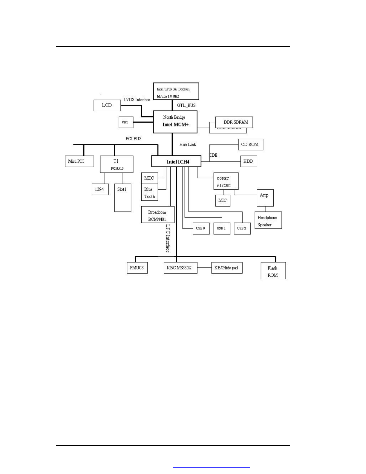
1.3 System Configuration
Figure 1-1 System Configuration Diagram
1-6 FIC MD02 Service Manual
PDF created with FinePrint pdfFactory trial version http://www.fineprint.com
Page 7
Outline of the MD02
1.4 Quick Tour of the Notebook
Please take a moment to become familiar with the location and purpose of every control, the
LED status panel, connectors and ports, which are illustrated in this section. It is
recommended to first go through the User Guide of the notebook, which is shipped together
with the notebook for information on how to operate its features.
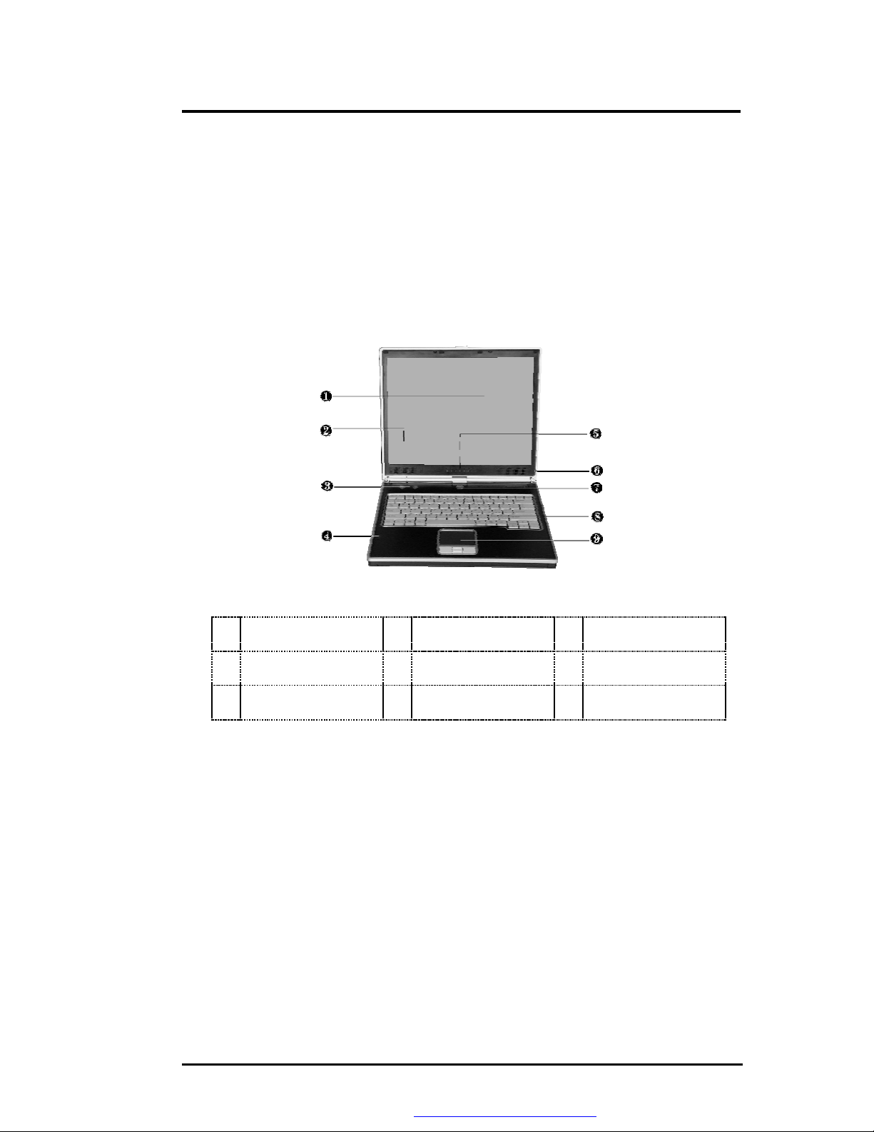
1.4.1 The Inside of the Notebook
To open the LCD cover of the notebook, find the cover latch located at the front center of the
LCD cover. Push the latch to the right to release and tilt the LCD cover up. Inside, you will see
the LCD display panel, keyboard, touch pad, status LED, and power switch.
Figure 1-2 The Inside side of the Notebook
Color LCD Display
Œ
•
’
Integrated
Microphone
Power On/Resume
Button
• Color LCD Display
The notebook computer comes with a color LCD that you can adjust for a
comfortable viewing position. The LCD can be 14.1" TFT color LVDS with
1024x768 XGA (Extended Graphics Array) or 1400x1050 SXGA+ resolution
panels. The features of the Color LCD Display are summarized as follows:
⇓ TFT color LVDS with 14.1" 1024x768 XGA or 14.1" 1400x1050 SXGA+
resolution panels.
⇓ Capable of displaying 16M colors (32-bit true color) on either size panels.
⇓ LCD display control hot-keys allows you to adjust the brightness of the
LCD.
⇓ Simultaneous display capability for LCD and external desktop computer
monitor.
Built-in Stereo
•
Speakers
Status LED
•
Indicator
➑
Keyboard
Ž
‘
❾
Easy Buttons
Built-in Stereo
Speakers
Touchpad Pointing
Device
FIC MD02 Service Manual 1-7
PDF created with FinePrint pdfFactory trial version http://www.fineprint.com
Page 8

Outline of the MD02
•
Built-in Stereo Speakers
Integrated left and right mini stereo speakers located at the bottom of LCD
panel for sound and audio output for your multimedia presentations or
listening pleasure.
•
Easy Buttons
There are two easy buttons used for accessing Internet and e-mail functions
instantly and easily. Description of the easy buttons appears in the latter part
of this section.
•
Integrated Microphone
Integrated mono microphone for instant voice recording and simultaneous
voice conversation.
•
Status LED Indicator
Keeps you informed of your notebook computer’s current power status and
operating status. Description of the status icons appears in the latter part of
this section.
•
Power On/Resume Button
Switches the computer power on and off, or resumes whenever it is in
Suspend mode.
•
Keyboard
⇓
Standard QWERTY-key layout and full-sized 82/84 keys keyboard with
Windows system hot-keys, embedded numeric keypad, 7 hot keys,
inverted "T" cursor arrow keys, and separate page screen control keys.
⇓
Wide extra space below the keyboard panel for your wrist or palm to siton comfortably during typing.
•
Touchpad Pointing Device
Microsoft and IBM PS/2 mouse compatible with three select buttons as one
Scroll button and two Touchpad click buttons. These three buttons array
below the Glide pad. The middle one is located with the Scroll button that lets
you execute the scroll page function. The two click buttons located at each
side support tapping selection and dragging functions. These buttons work
like a standard computer mouse. Simply move your fingertip over the Glide
Pad to control the position of the cursor. Use the selection buttons below the
Glide Pad to select menu items.
Easy Buttons
There are three easy buttons, two use for accessing Internet and e-mail functions instantly
and easily, the other one lets you define certain functions by yourself. Descriptions of the
easy buttons appear in the latter part of this section.
1-8 FIC MD02 Service Manual
PDF created with FinePrint pdfFactory trial version http://www.fineprint.com
Page 9

Outline of the MD02
Internet Button
Œ
Figure 1-3 Easy Button
• Internet Button
This technology is designed specifically for providing a very convenient way
in connecting Internet only by pressing Internet button as shown in the
graphics. For more understanding and interesting, you can refer Section 2.5
to recognize the driver installation procedures in activating Internet button.
• E-mail Button
This is the most convenient way to access the outlook 98/2000/2002... utility
just by pressing this button. You can simplify several procedures in entering
into Outlook 98/2000/2002... environment.
Status LED Indicator
Located just in front of the palmrest assembly, you will find three LEDs for the power and
battery charge status. These LEDs are positioned to be visible even if the LCD cover is
closed.
•
E-Mail Button
Figure 1-4 Status LED Indicator
Œ
Power Indicator
•
Wireless LAN Access
Num Lock
❼
• Power Indicator
Lets you know that power to the system is turned on. This LED is positioned
so that you can see the power state whether the LCD panel is opened or
closed.
•
Battery charging LED
•
Caps Lock
FIC MD02 Service Manual 1-9
PDF created with FinePrint pdfFactory trial version http://www.fineprint.com
Ž
Drive Access
‘
Scroll Lock
Page 10

Outline of the MD02
⇓
Lights green when the system is powered on
⇓
Lights green blinking when the system is in Suspend to RAM.
•
Battery Charging LED
Lights to indicate battery in charging status.
⇓
Lights green to indicate that the battery is in charging.
⇓
Lights off to indicate the battery is fully charged or no battery installed.
•
Drive Access
When LED in green light indicates that the system is accessing either the
Hard Disk or Combo drive.
•
Wireless LAN access
When LED in green light indicates that the wireless LAN module is installed.
When LED in blinking green light indicates that the system is accessing or
retrieving data by wireless device.
•
Caps Lock
When LED in green light indicates that the Caps Lock key on the keyboard is
activated. When activated, all alphabet keys typed in will be in uppercase or
capital letters.
1.4.2 The Front Side of the Notebook
Œ Cover Switch • Battery
Figure 1-8 The Front Side of the Notebook
• Cover Switch
The cover (LCD panel) is locked when it is closed. Slide the button right aside
to release the latch for opening the cover of the computer.
•
Battery
The battery pack is inserted here.
1-10 FIC MD02 Service Manual
PDF created with FinePrint pdfFactory trial version http://www.fineprint.com
Page 11

Outline of the MD02
1.4.3 The Rear Side of the Notebook
The rightt side of the notebook computer offers the features shown in the following figure.
Air-Outlet Vent
Œ
CRT Port
•
Modem Port
’
Figure 1-9 The Rear side of the Notebook
• Air-Outlet Vent
Emits the heat out of your computer and keeps it within operating
temperature.
• DC Power Port
Lets you connect the AC power adapter in supplying continuous power to
your notebook and recharging the battery.
• Air Inhalant
Inhale the air into your computer to keep it within operating temperature.
• Monitor Port
Lets you attach an external monitor or projector for wider display. You can
run the LCD display and the external monitor simultaneously or switch it to
monitor only using the display hot-key.
• USB Port
The Universal Serial Bus (USB) port allows you to connect up to 127 USBequipped peripheral devices (for example, printers, scanners and so on) to
your notebook computer.
AC Power Port
•
USB Port
•
‘
Air-Outlet Vent
Ž
LAN Port
• LAN Port
An internal 10Base-T/100Base-TX LAN module connects your computer to
other computers/networks through a local area network (LAN).
• Modem Port
A 56K internal fax/data modem is installed. It keeps you connected to the
outside world through networks.
FIC MD02 Service Manual 1-11
PDF created with FinePrint pdfFactory trial version http://www.fineprint.com
Page 12

Outline of the MD02
1.4.4 The Left Side of the Notebook
The left side of your notebook computer provides the features shown in the following figure.
To see all the ports located on the left side, you can open the cover first.
Microphone
Œ
Jack
PC Card Slot
•
Figure 1-10 The Left side of the Notebook
•
Microphone Jack
Allows you to connect an external microphone for monophonic sound
recording directly into your notebook computer.
•
Headphone Jack
Lets you plug in a stereo headphone, powered speakers, or earphone set
with 1/8 inch phono plug for personal listening.
•
IEEE 1394
IEEE 1394 port is a high speed I/O port that can transfer high levels of data in
real-time, such as external hard disk, Digital Video Camera.
•
PC Card Slot
⇓
Lets you connect various PC cards such as memory card
⇓
Supports both 3V, 5V 32-bit CardBus and 16-bit PC cards.
Headphone Jack
•
1.4.5 The Right Side of the Notebook
Ž
IEEE 1394
Œ
CD-ROM, DVD-ROM,
CD-RW module
• CD-RW/DVD Combo Drive
Allows you to load and start programs from a compact disc (CD) or a digital
video disc (DVD) and play conventional audio CDs. It also can make CD by
using CD-R or CD-RW.
Figure 1-11 The Right side of the Notebook
•
Locking Device
Keyhole
1-12 FIC MD02 Service Manual
PDF created with FinePrint pdfFactory trial version http://www.fineprint.com
Page 13

Outline of the MD02
•
Locking Device Keyhole
Lets you attach a Kensington security system or a compatible lock to secure
your notebook computer.
1.4.6 The Under Side of the Notebook
ΠBattery Release
Latch
• Battery Release Latch
• Battery Bay
• Hard Disk Compartment
Battery Bay Ž Hard Disk Compartment
•
Figure 1-12 Under Side of the Notebook
Push the latch to the left end to remove the battery pack.
Equipped with a choice of Lithium-Ion (Li-Ion) battery pack.
Open this cover of this compartment to replace with other Hard Disk Drive.
Please refer to Chapter 7 for how to replace it.
1.5 Notebook Accessories and System Options
It is also important to understand the accessories that come along with the notebook and the
options for fully utilizing the capabilities of the computer. This section describes briefly what
these accessories and options are.
1.5.1 AC Adapter and Power Cord
The AC Adapter supplies external power to your computer and at the same time charges the
internal battery pack. The AC adapter has an auto-switching design that can connect to any
100VAC ~ 240VAC power outlets. Connect the adapter to the AC wall outlet using the power
cord. You just change the power cord if you are going to use your notebook in other countries
with different connector outlets. When you connect the AC adapter, it charges the battery
whether or not the notebook computer is powered on. There is an LED on the AC adapter to
indicate if DC power is already available.
1.5.2 Battery Pack
Aside from the AC adapter, your computer can also be powered through the internal battery
pack. The battery pack uses rechargeable Lithium-Ion (Li-Ion) battery cells that provide long
computing hours when fully charged and power management enabled. You should always
leave the battery inside your computer even when using the AC adapter as it also acts as a
FIC MD02 Service Manual 1-13
PDF created with FinePrint pdfFactory trial version http://www.fineprint.com
Page 14

Outline of the MD02
back-up power supply in case power from the AC adapter is cut off. It is also very important to
have the battery pack always charged to prevent battery cell degradation.
1.5.3 Internal Modem Module
The notebook allows you to insert a proprietary internal 56Kbps-modem card to the notebook
found on the underside of the notebook. The internal modem card supports only fax and data
communication and is V.90-compliant. You connect the telephone line to the RJ-11 jack found
on the rear side of the notebook.
1.5.4 Internal Ethernet LAN Module
This notebook comes with an optional 10Base-T/100Base-TX LAN module that supports data
transfer rates at 10Mbps and can be up to 100Mbps.
1.5.5 DVD-ROM Drive
Other than the internal CD-ROM drive, the notebook also provides optional factory built-in
DVD-ROM drive. DVD-ROM drives are also backward compatible with CD-ROM, so you can
also use any audio CDs, video CDs, photo CDs, and CD-R. Using a software MPEG-2/DVD
program, the notebook can playback any commercial DVD movie titles.
1.6 System BIOS SETUP Program
Your computer is likely to have been properly setup and configured by your dealer prior to
delivery. However, you may find it necessary to use the computer’s BIOS (Basic Input-Output
System) Setup program to change system configuration information, such as the current date
and time, or your hard disk drive type. The Setup program can be accessed when you power
on the system and pressing the <F2> function key.
The settings that you specify within the Setup program are recorded in a special area memory
called the
when you turn off or reset the system. Whenever you turn on the computer, the system will
read the settings stored in the CMOS RAM and compare them to the equipment check
conducted during the Power On Self Test (POST). If an error occurs, an error message will be
displayed on the screen, and you will then be prompted to run the Setup Program.
As the POST (Power-On Self Test) executes during the boot up process, the screen will
display the following message:
CMOS RAM
. This memory is backed up by a battery so that is will not be erased
Press <F2> to Enter SETUP
Press the <F2> key to run the BIOS Setup program. The BIOS Setup program is organized
into five menus which you can select using the ß and à keys. To move from one option to
another, you use the up and down arrow keys while using the <F5> and <F6>, or <+>and <->
keys to change the settings. On the right hand side of the screen are some brief help
descriptions of each item you want to change.
On the BIOS Setup program, you will find the following parts on the screen:
•
Item Specific Help
The right side of the screen. This area describes each parameter and its
available settings.
• Menu Bar
The top line of the screen. Each of the five selections displays its own screen.
• Parameters
The left side of the screen. This area lists the parameters and their current
settings.
• Key Status Bar
The bottom part of the screen. These lines display the keys available to move
the cursor, select a particular function and so forth.
To exit the BIOS Setup program, simply press the <Esc> key and select from the Exit menu
whether you want to Save changes and exit; Discard Changes and exit.
1-14 FIC MD02 Service Manual
PDF created with FinePrint pdfFactory trial version http://www.fineprint.com
Page 15

Outline of the MD02
System Tim
e: [12 :00 :00]
<Tab>, <Shift
-
1.6.1 Using the Main Menu Setup
PhoenixBIOS Setup Utility
Main Advanced Security Boo Exit
Item Specific
System Date: [05/20/2002] or <Enter>
Language: [English (US)] field.
Legacy USB
Support:
Internal HDD: [20004MB]
4
Internal DVD/CD-
ROM
Boot Display
Device:
System Memory: 640 KB
Extended Memory: 114687 KB
CPU Type: Celeron (TM)
CPU Speed: 1066 MHz
BIOS Version: 0.3C-0022-0713
F1 Help
Es
Exit
c
Select Item -/+ Change
á â
Select
ßà
Menu
[Enabled]
Installed
[Both]
Enter Select 4Sub-
Values
Menu
selects
F9 Setup
Defaults
F10 Save and
Exit
•
System Time
Allows you to change the system time using the hour:minute:second format
of the computer.
Enter the current time for reach field and use the <Tab>, <Shift>+<Tab>, or
<Enter> key to move from one field or back to another.
You can also change the system time from your operating system.
•
System Date
Allows you to set the system date using the month/date/year format.
Enter the current time for reach field and use the <Tab>, <Shift>+<Tab>, or
<Enter> key to move from one field or back to another.
You can also change the system time from your operating system.
•
Language
This field shows the Language version of the BIOS.
FIC MD02 Service Manual 1-15
PDF created with FinePrint pdfFactory trial version http://www.fineprint.com
Page 16

Outline of the MD02
•
Legacy USB Support
Allow you to select the Enabled or Disabled option for enabled or disabled
the USB port.
•
Internal HDD
This field displays various parameters for the hard disk drive. If type [Auto] is
selected, the system automatically sets these parameters. If type [User] is
selected, Cylinders, Heads and Sectors can be edited.
•
Internal DVD/CD-ROM
This field is for information only as the BIOS automatically detects the CDROM/DVD-ROM.
•
Boot Display Device
Lets you select the display device.
•
System Memory
This field reports the amount of base (or conventional) memory found by the
BIOS during Power-On Self-Test (POST).
•
Extended Memory
This field reports the amount of extended memory found by the BIOS during
Power-On Self-Test (POST).
•
CPU Type
This field reports the CPU type information detected by the BIOS during
Power-On Self-Test (POST).
•
CPU Speed
This field reports the CPU speed information detected by the BIOS during
Power-On Self-Test (POST).
•
BIOS Version
This field is for information only as the BIOS displays the BIOS version during
the Power-On Self-Test (POST).
1-16 FIC MD02 Service Manual
PDF created with FinePrint pdfFactory trial version http://www.fineprint.com
Page 17

Type:
[Auto]
User = you
Outline of the MD02
1.6.2 Internal HDD Sub-Menu
PhoenixBIOS Setup Utility
Main Advanced Security Boo Exit
Internal HDD: [20004MB] Item Specific
parameters of
hard-
Multi-Sector
Transfers:
LBA Mode Control: [Enabled] at the
Auto =
32 Bit I/O: [Disabled] Hard-disk drive
Transfer Mode: [FPIO 4/DMA 2] installed here.
SMART Monitoring: Enabled None = no
Ultra DMA Mode: [Mode 5] installed here.
CD-ROM = a
ROM drive is
installed here.
F1 Help
Es
Exit
c
Use the Type field to select the drive type installed. You can select different drive types as
CD-ROM, User, Auto,
computer will automatically detect the drive type during power on. Set this option to None
when your computer is not installed any devices. Press <
Select Item -/+ Change
á â
Select
ßà
Menu
None
or
by pressing <
[16 Sectors] disk drive
installed
Connection.
autotypes
device is
CD-
F9 Setup
Values
Enter Select 4Sub-
Menu
Space
> bar. Set this option to Auto so your
Esc
> to return to the Main Menu.
Defaults
F10 Save and
Exit
FIC MD02 Service Manual 1-17
PDF created with FinePrint pdfFactory trial version http://www.fineprint.com
Page 18

Outline of the MD02
1.6.3 Using the Advanced CMOS Setup
PhoenixBIOS Setup Utility
Main Advanced Security Boo Exit
Item Specific Help
PS/2 Mouse: [Enabled] ‘Disabled ’
LCD Panel View
Expansion:
from functioning,
Silent Boot: [Enabled] frees up IRQ12.
Frame Buffer Size: [16 MB] 'Enabled' allows
operating system
I/O Device
4
Configuration
enable or disable
mouse
F1 Help
Es
Exit
c
Select Item -/+ Change
á â
Select
ßà
Menu
[Enabled] installed PS/2
determine
Values
Enter Select 4Sub-
Menu
prevents any
mouse
but
the
to
whether to
the
F9 Setup
Defaults
F1
Save and
0
Exit
• PS/2 Mouse
[Enable] allows the OS to enable or disable the PS/2 mouse when it is
detected. [Disabled] prevents any installed PS/2 mouse from functioning.
• LCD Panel View Expansion
Expands or keeps the original LCD Screen View during the booting
procedure. Expands may get full screen LCD display, however, it degrades
the graphic/text quality.
• Silent Boot
Lets you specify the boot screen as Logo screen, POST screen, or Black
screen by choosing Enabled, Disabled, or Black option, respectively.
• Frame Buffer Size:
Lets you specify the sharing memory size of the Video chip from SDRAM.
The Default sharing size is 16MB. You should carefully specify the value,
since while the set value is too high, the memory size of your software
application will be reduced.
• I/O Device Configuration
Lets you configure input/output device such as Serial Port, Parallel Port, and
Floppy disk controller.
1-18 FIC MD02 Service Manual
PDF created with FinePrint pdfFactory trial version http://www.fineprint.com
Page 19

Outline of the MD02
1.6.4 I/O Device Configuration Sub-Menu
PhoenixBIOS Setup Utility
Main Advanced Security Boo Exit
I/O Device Configuration Item Specific
Serial port A: [Auto] Configure serial
Infrared port: [Enabled] using options:
Mode: [IrDA] [Disabled]
Base I/O address: [2E8 IRQ3] No
Parallel port: [Auto]
Mode: [EPP] [Enabled]
User
Floppy disk controller: [Disabled]
[Auto]
BIOS or OS
configuration
F1 Help
Es
Exit
c
á â
ßà
Select
Item
Select
Menu
-/+ Change
Values
Enter Select 4Sub-
Menu
configuration,
configuration
chooses
F9 Setup
Defaults
F10 Save and
Exit
• Serial port
You can select the Enabled, Disabled, or Auto option for enabled or disabled
the port, or automatically sensed by BIOS or OS. If you select Enable, you
also need to set the parameter of Base I/O address and IRQ.
• Infrared port
You can select the Enabled, Disabled, or Auto option for enabled or disabled
the port, or automatically sensed by BIOS or OS. If you select Enable, you
also need to set the IR mode, Base I/O and IRQ for the IR device.
• Mode
This field is for information only as the BIOS displays the IR device type of
this notebook.
• Parallel port
Allows you to select the Enabled, Disabled, or Auto option for enabled or
disabled this port, or automatically sensed by BIOS or OS. If you select
Enable, you also need to set the parameter of Base I/O address.
• Mode
Allows you to select a parallel mode as Uni-directional, EPP or ECP when the
parallel port is configured.
• Floppy disk controller
FIC MD02 Service Manual 1-19
PDF created with FinePrint pdfFactory trial version http://www.fineprint.com
Page 20

Outline of the MD02
This field is for information only as the BIOS displays the floppy disk
controller of this notebook.
1-20 FIC MD02 Service Manual
PDF created with FinePrint pdfFactory trial version http://www.fineprint.com
Page 21

Outline of the MD02
Set Supervisor P
assword
[Enter]
Supervisor
1.6.5 Security Menu Setup
PhoenixBIOS Setup Utility
Main Advanced Security Boo Exit
Item Specific
Set User Password [Enter] controls access
setup utility.
Password on boot [Disabled]
Fixed disk boot sector [Normal]
Diskette access [Supervisor]
F1 Help
Es
Exit
c
á â
ßà
Select
Item
Select
Menu
-/+ Change
Values
Enter Select 4Sub-
Menu
F9 Setup
Defaults
F10 Save and
Exit
• Set Supervisor Password
Supervisor password gives you the authority in accessing the setup utility.
You also need to enter this password in system booting and resuming from
suspend mode. When you press <
Password dialog box appears. Enter a new password with up to 8 alphanumeric characters, and then re-enter it for confirmation.
• Set User Password
This field is only available when Supervisor Password has set. Enter the user
password when boot the system or resume from suspend mode. But if the
Write Protect is set in the Fixed disk boot sector field, you should enter a
supervisor password to access the fixed disk when boot the system or
resume from suspend mode.
• Password on Boot
If you set this field to Enabled, your computer will always ask for the
password every time you boot your computer.
• Fixed Disk Boot Sector
If you set this field to Write Protect, the write protect boot sector on hard disk
will protect against viruses. In this situation, only the supervisor can access
the Boot Sector of fixed disk.
• Diskette Access
If you set this field to Supervisor, only the supervisor can access to the
diskette drives. If you set to User, both the supervisor and user can access to
the diskette drives.
Enter
> in this field, the Set Supervisor
FIC MD02 Service Manual 1-21
PDF created with FinePrint pdfFactory trial version http://www.fineprint.com
Page 22

Outline of the MD02
1.6.6 Using the Boot Setup
This item allows you to set the search drive sequence where the system will try to boot up first.
PhoenixBIOS Setup Utility
Main Advanced Security Boot Exit
Item Specific Help
Removable Devices Use <á> or <â>
to
+Hard Drive select a device,
CD-ROM Drive press <+> or <-> to
move
the device up or
down
<Enter> expands
or
collapses device.
F1 Help
Es
Exit
c
To select the boot device, you can use the up or down arrow key, then press <+> to move up
the device in the list or press <-> to move down the device in the list. To exit from this menu,
press <
Esc
>.
á
â
ß
à
Select
Item
Select
Menu
-/+ Change Values F9 Setup
Defaults
Ent
Select 4Sub-
er
Menu
F10 Save and Exit
1-22 FIC MD02 Service Manual
PDF created with FinePrint pdfFactory trial version http://www.fineprint.com
Page 23

Exit System
Outline of the MD02
1.6.7 How to Exit the Setup Program
There are two choices to escape from the Setup program.
PhoenixBIOS Setup Utility
Main Advanced Security Boo Exit
Item Specific
Exit Saving Changes
Exit Discarding
Changes
Load Setup Defaults changes to
Discard Changes
Save Changes
Battery Refresh
F1 Help
Es
Exit
c
Select Item F5/F6 Change Values F9 Setup
á
â
Select
ß
Menu
à
and save your
Enter Execute
Command
CMOS.
Defaults
F10 Save and
Exit
• Exit Saving Changes
Saves all changes to CMOS while running the BIOS setup program and exit
from the system setup program.
• Exit Discarding Changes
Allows you to discard all changes made while running the BIOS setup
program and exit from the system setup program.
• Load Setup Defaults
Lets you load the default values for all setup items.
• Discard Changes
Reverts to previously selected settings.
• Save Changes
Saves Setup data to CMOS.
• Battery Refresh
Conditions the battery so that the battery can be fully charged.
1.6.8 How to Upgrade the BIOS
Your computer uses EPROM Flash BIOS chip that allows you to easily upgrade the BIOS
program. When you update the BIOS, any customized settings you made are lost.
To upgrade the BIOS:
1. Insert the BIOS Update diskette into the diskette drive.
2. Power on the system with the diskette in the diskette drive.
FIC MD02 Service Manual 1-23
PDF created with FinePrint pdfFactory trial version http://www.fineprint.com
Page 24

Outline of the MD02
3.
On the DOS prompt, type the following command.
A:\>Phlash XXXXXX.ROM (BIOS filename)
A:\>XXXXXX.BAT (Batch file for BIOS file)
4. Press <Enter> to run this BIOS utility. After the system has been successfully
run this program, a message similar to the following appears:
Flash memory has been successfully programmed, press any key to restart
the system. If the system does not restart, turn it off, then turn on again.
5. Press any key to restart this system.
Contact your dealer for the latest BIOS update file.
or
1-24 FIC MD02 Service Manual
PDF created with FinePrint pdfFactory trial version http://www.fineprint.com
 Loading...