

Page 1

KW15
MAINBOARD
MANUAL
DOC No.: M99901
Rev. : A1
Date : 11, 1999
Part No. : 25-11023-21
Page 2

Notice
Handling Precautions
Warning:
1. Static electricity may cause damage to the integrated circuits on
the motherboard. Before handling any motherboard outside of its
protective packaging, ensure your body is not electrostatiscally
charged.
2. There is a danger of explosion if the battery is incorrectly
replaced. Replace only with the same or an equivalent type
of battery as recommended by the manufacturer.
3. Discard used batteries according to the manufacturer’ s
instructions.
Observe the following basic precautions when handling the motherboard
or other computer components:
n Wear a static wrist strap which fits around your wrist and is
connected to a natural earth ground.
n Touch a grounded or anti-static surface or a metal fixture such as a
water pipe.
n Ensure add-on cards, mainboards, and modules do not come into
contact with the golden fingers connectors, plugged into the
expansion slot.
The above methods prevent static build-up and allow it to be discharged
properly.
Trademark
All trademarks mentioned in this manual are registered property of
the respective owners.
Handling Precautions
This manual may not, in whole or in part, be photocopied, reproduced,
transcribed, translated, or transmitted in whatever form without the
written consent of the manufacturer, except for copies retained by the
purchaser for personal archival purposes.
Page 3

T able of Contents
Table of Contents
Chapter 1 Overview
Mainboard Layout ......................................................................... 1-2
System Specifications .................................................................... 1-3
Features Highlight ......................................................................... 1-5
Add-on Features for VGA in Intel 810/E ................................... 1-5
Add-on Features for Audio ....................................................... 1-6
AMR and AC97 CODEC Controller ......................................... 1-6
Modem Ring On ........................................................................ 1-7
SB-Link Sideband Signals ......................................................... 1-7
Ultra DMA 66 Cable (optional) ................................................. 1-7
ACPI Ready ................................................................................... 1-8
FIC Unique Innovation for Users (NOVUS) -
Enhanced Mainboard Features and System Support .................... 1-8
Chapter 2 Installation Procedures
QUICK REFERENCE ...................................................................... 2-2
CPU Installation ............................................................................. 2-7
Socket 370 ................................................................................. 2-7
SLOT1 ....................................................................................... 2-8
System Memory Installation .......................................................... 2-9
DIMM Type, Size, Parity Supported ......................................... 2-9
Expansion Cards Installation ......................................................... 2-10
Mainboard Layout ......................................................................... 2-12
System Jumpers ............................................................................. 2-14
CMOS Clearance Function: JP8 ................................................. 2-15
Audio CODEC Enable: JP9 ........................................................ 2-15
CPU Socket Type Select: JP2, JP10 ............................................ 2-16
BIOS Top Block Lock Select: JP3 .............................................. 2-16
Reboot on Timeout: JP1 ............................................................ 2-16
BIOS Setting CPU Ratio: JP4 ..................................................... 2-17
Connectors .................................................................................... 2-17
Floppy Diskette Drive Connector: Floppy ................................ 2-17
IDE HDD Device Connectors: IDE1, IDE2 ................................. 2-18
PCI Add-On Audio Card Connector: SB-LINK ......................... 2-18
ATX Power Connector: PW1 .................................................... 2-19
CPU Fan Connector: CPU-FAN ................................................. 2-19
i
Page 4

KW15 Mainboard Manual
System Case Fan Connector: CHS-FAN .................................... 2-20
Infrared Connector: IR1 ............................................................. 2-20
CD Audio-Out Connector: CD1, CD2 ........................................ 2-21
Power Fan Connector: PWR-FAN ............................................. 2-21
Front Panel Block Connector: FIC1 ........................................... 2-22
Video Graphics Accelerator Connector: VGA ............................ 2-23
PS/2 Keyboard and Mouse Connector: KBMS1 ....................... 2-23
Universal Serial Bus Connectors: USB ...................................... 2-24
Printer Connector: LPT1 ............................................................ 2-24
Serial Port Connectors: COM1, COM2 ...................................... 2-25
Joystick/MIDI Connector: GAME ............................................. 2-25
Audio I/O Jacks: LINE_OUT, LINE_IN, MIC_IN ...................... 2-26
Chapter 3 BIOS Setup
BIOS Configuration Setup ............................................................. 3-2
Chapter 4 FAQ s
General FAQs ................................................................................. 4-1
BIOS FAQs .................................................................................... 4-3
Windows 98/98 SE FAQs ............................................................... 4-5
Windows 95 FAQs ......................................................................... 4-6
ii
Page 5

Overview
Chapter 1
Overview
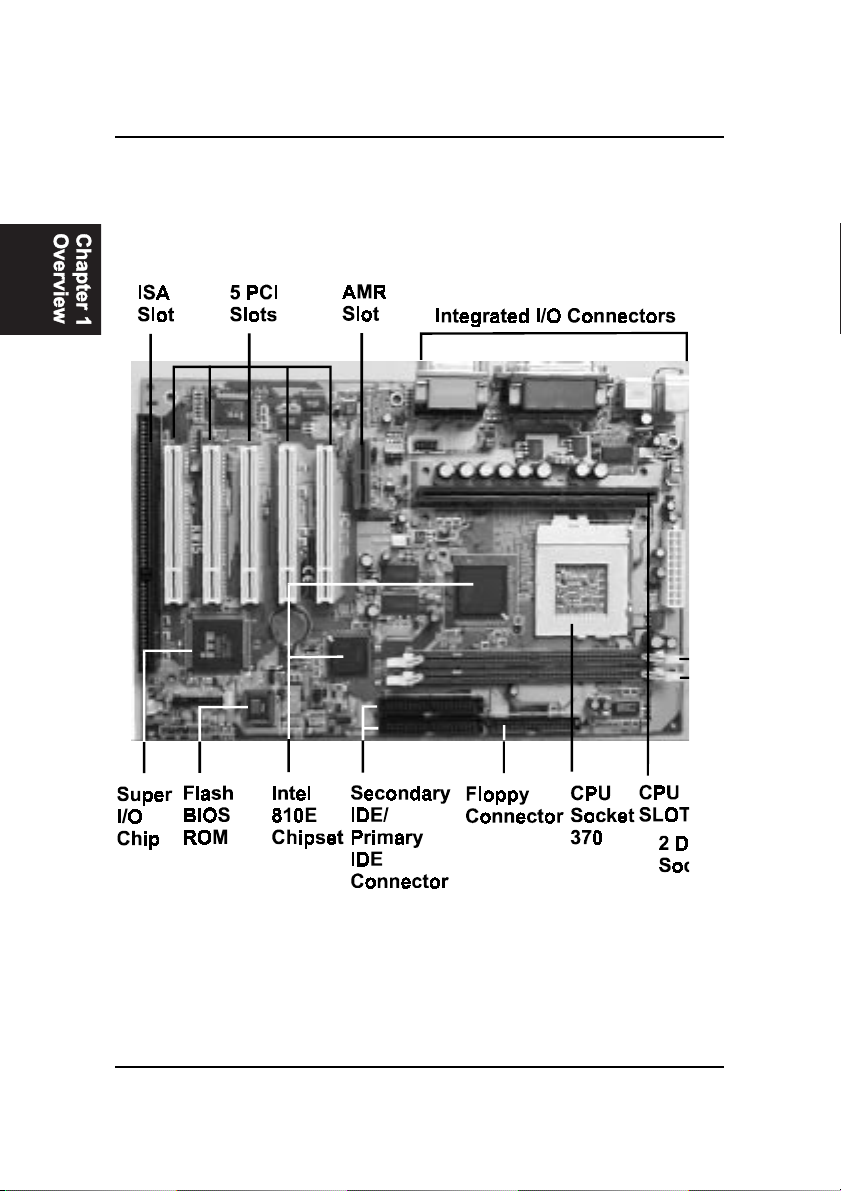
The smart ATX sized 1stMainboard KW15 features a choice of the Slot 1 and
the highly scalable Socket 370 processor. A full range of Intel® Celeron and
Pentium® II/III processors are supported at speeds up to 733MHz with Front
Side Bus speeds of 66, 100 and 133 MHz. The Slot 1 / Socket 370 flexibility
allows for convenient processor upgrades to meet the changing demands of
new productivity software. The advantages of having the CPU choice on
board rather than utilizing a CPU adapter card are a shorter local bus trace time
and less noise interference providing extra reliability and performance.
The Intel 810/E accelerated Hub architecture provides exceptional onboard
video. Direct AGP and its efficient memory utilization allows a 4MB SDRAM
display cache and Dynamic Video Memory Technology which provides the
equivalent of 8 MB video memory performance.
Support for the Ultra DMA/66 protocol and its high-speed interface further
ensures that data transfer speeds are improved, especially for long sequential
transfers required by audio/visual applications. With 2 DIMM there is up to
512 MB available SDRAM. In addition, the 1stMainboard KW15 is equipped
with 2 dual channeled enhanced PCI bus master IDE connectors.
Power-On management features include Keyboard/Mouse Power On, Wake
on Ring ( WOR ) with Modem system boot support.
The 1stMainboard KW15 comes with a versatile range of I/O features such as
2 serial ports, 1 parallel port, 1 PS/2 mouse and keyboard connector, 2 USB
connectors, 1 VGA connector and 1 media connector ( MIDI /game port, Line-
in, Line-out and Mic-in). Ample expansion is available through 5 PCI, 1 AMR
and 1ISA ( mfg. option ).
1 - 1
Page 6
KW15 Mainboard Manual
Mainboard Layout
1 - 2
Page 7

System Specifications
■ Flexible Processor Support
n Single CPU, with both Slot 1 and PPGA Socket 370 on board for
choice.
n Supports CPU Clock 66MHz, 100MHz and 133MHz. CPU Clock
Ratios from 3.0x to 8.0x (step 0.5x).
n Support CPUs: Pentium II 233MHz~450MHz, Celeron
300MHz~533MHz, and Pentium III 450MHz~733MHz.
n CPU Core Voltage 1.30V~2.05V (step 0.05V), and 2.1V~3.5V (Step
0.1V); CPU~I/O Voltage 3.3V.
n Built-in Switching Voltage Regulator, supporting Vcore autodetection.
■ Memory Support
n SingleTwo DIMM sockets on board supporting up to 512MB
SDRAM.
n PC-66 / PC-100 compatible.
■ I/O System
n On-board Intel 810 Chipset for I/O Control:
FW82810DC100 / FW82810E + FW82801AA.
Overview
n Bus Frequency 66/100/133MHz
n 5 PCI slots on board, compliant with version 2.2 PCI Local Bus spec.
n One Optional ISA slot.
n One AMR (Audio, Modem Riser) slot on board.
n Dual Master IDE connectors, supporting UDMA33/66 for 4 IDE
devices such as high capacity HDD, CD-ROM, LS-120 and tape
backup etc.
n Two USB connectors in stack supporting up to 127 USB devices.
1 - 3
Page 8

KW15 Mainboard Manual
■ PS/2 Keyboad and PS/2 Mouse connectors.
■ One Infrared (IrDA TX/DX) connector.
■ One FDD port supporting two Floppy drives of : 1.2MB / 1.44MB /
2.88MB.
■ One parallel port for SSP/EPP/ECP mode printer.
■ Two 16550A Fast UART compatible connectors for serial and VGA
port.
■ One Game /Midi port and 3 Audio Jacks for Speak-out, Line-in and
Microphone-in.
■ One SB-Link Connector for Sound Card and PCI connection.
■ BIOS Support
■ Built-in VGA BIOS in Intel 810/E; and built-in Keyboard BIOS;.
■ AWARD BIOS in Intel 810/E, providing CMOS Setup Utilities:
- Standard CMOS Features Setup for Date, Drives and VGA;
- Advanced BIOS Features Setup for CPU Cache, Self Test,
Boot Device, Typematic Rate , and Security Options etc.;
1 - 4
- Advanced Chipset Features Setup for SDRAM CAS, RAS,
System BIOS Cacheable, and Video BIOS Cacheable etc.;
- Integrated Peripherals Setup for IDE Mode, USB, Audio,
and Modem etc.;
- Power Management Setup on Video, HDD, CPU etc.;
- PnP/PCI Configurations Setup for PnP, Reset, Resources etc.;
- PC Health Status Control and Setup;
- Frequency / Voltage Control on CPU, SDRAM, PCI & SSC etc.;
- Load Fail-Safe Defaults and Load Optimized Defaults;
- Set Supervisor/User Password;
Page 9

■ Board Dimension:
308mm x 202mm, in ATX form Factor. with one ATX Power Connector.
Features Highlight
Add-on Features for VGA in Intel 810/E
■ Integrated Graphics Controller
■ 3D Hyper Pipelined Architecture.
■ Full 2D H/W Acceleration.
■ Motion Video Acceleration.
■ 3D Graphics Visual Enhancements
■ Flat & Gouraud Shading.
n Mip Maps with Bilinear and Anisotropic Filtering.
n Fogging Atmospheric Effects.
n Z Buffering.
Overview
n 3D Pipe 2D Clipping.
n Backface Culling.
■ 3D Graphics Texturing Enhancements
n Per Pixel Perspective Correction Texture Mapping.
n Texture Compositing.
n Texture Color Keying/Chroma Keying.
n Integrated 24-bit 230MHz RAMDAC.
1 - 5
Page 10
KW15 Mainboard Manual
n 2D Graphics
n Up to 1600 x 1200 in 8-bit Color at 85 Hz Refresh.
n Hardware Accelerated Functions.
n H/W Motion Compensation Assistance for S/W MPEG2 Decode
n Software DVD at 30fps.
n H/W Overlay Engine with Bilinear Filtering.
n Intel 810 ICH with built-in AC97 controller.
Add-on Features for Audio
n Intel 810 ICH with built-in AC97 controller.
n Supporting HRTF-based 3D positional audio, A3D, Q3D, wavetable,
and 3D surround sound.
NOTE: If you want to enable the onboard AC’97 CODEC, you need
to set JP9 pin 1-2 closed. But in this way, the AMR slot will only
accept a riser board with Modem CODEC and cannot accept another Audio Riser.
AMR and AC’97 CODEC Controller
AMR slot and AC97 CODEC are integrated into the Mainboard to enable
audio and modem playback.
AMR (Audio/Modem Riser) slot is mounted on board to connect riser board
with Audio and/or Modem CODEC (AMC/AC/MC Adapters). The AMR speci-
fication developed by Intel provides a mechanism for AC97 codes to be on a
riser card.
To enable the onboard AC97 CODEC, set JP9 pin 1-2 closed. And in such
way, you can further plug a riser board with Modem CODEC to the AMR slot.
Otherwise, disabling onboard AC97 CODEC by setting JP9 2-3 closed, you
can plug a riser board with Audio/Modem CODEC to the AMR slot.
1 - 6
Page 11
Overview
Modem Ring On
With Modem Ring On function, the computer can wake up by remote signal
through a connected modem. This function enables users to access their
computer data from anywhere in the world. Users have to enable Power On
by Ring in Power Management Setup of the AWARD BIOS setup screens.
SB-Link Sideband Signals
In order to migrate the legacy Sound Blaster compatible audio to the PCI bus,
EMU8008 incorporates a pair of SB-Link request/grant sideband signals
(PCPCIR EQN and PCPCIGNTN) to interface to the PCI bus. SB-Link is a
mechanism that was defined and developed by Intel as a docking solution
which allows ISA slots to exist in docking stations connected to desktop PC
PCI bus. The figure below is the pin assignments on the mainboard.
Ultra DMA 66 Cable (optional)
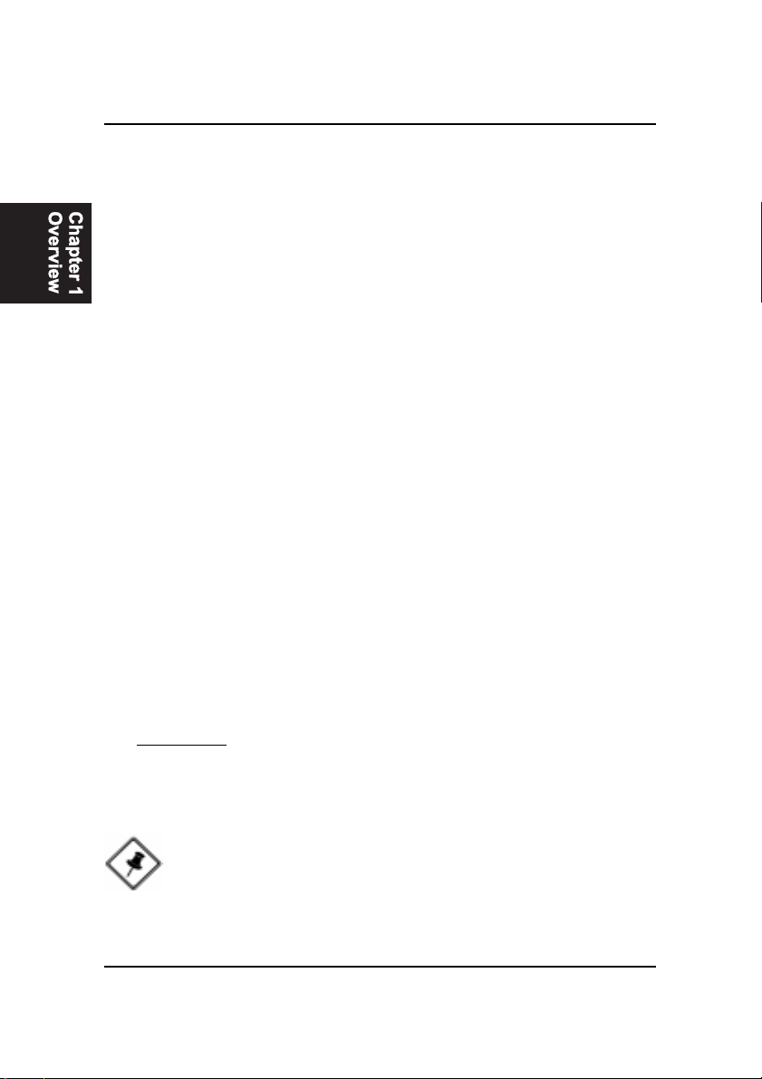
Ultra DMA 66 cable (40-pin connector & 80-line cable) is packaged while
utilizing FW82801AA chip which supports both UDMA 33 & UDMA 66 on
the mainboard. In other words, Ultra DMA 33 cable is only used with
FW82801AB chip And the Ultra DMA 66 color coded connectors are shown
as bellow:
1 - 7
Page 12
KW15 Mainboard Manual
ACPI Ready
This mainboard fully implements the new ACPI (Advanced Configuration and
Power Interface) 1.0 Hardware and BIOS requirement. If you install ACPI aware
operating systems, such as Windows 98, you can fully utilize the power sav-
ing features under ACPI.
It is compatible with all other non-aware ACPI operating systems. If you want
to setup ACPI features under Windows 98, please follow the instruction be-
low:
Run Windows 98 setup by using setup/p j on the command line for installing
Windows 98 with the ACPI control features.
If you type setup without the parameter /p j, Windows 98 will be installed as
APM, PnP mode, no ACPI will be used.
For more detail information, please visit the web site of Microsoft. The URL is:
www.microsoft.com/hwtest/.
FIC Unique Innovation for Users (NOVUS) -
Enhanced Mainboard Features and System Support
■ LogoGenie
A user friendly GUI supporting Windows 98, LogoGenie allows you to
customize, create or select a Logo which will be displayed when the sys-
tem is booting.
Important: Before executing this LogoGenie function, please make
sure the related BIOS feature, BIOS Guardian, is disabled; and refer to
its related README file.
NOTE:
1. LogGenie supports Award BIOS only.
2. If you create a Logo file (.bmp) by LogoGenie, the file size must
||||be 640 x 464 x 16 colors (around 145K).
1 - 8
Page 13

Overview
To enable this utility, please proceed as follows:
1. Insert CD Pro 4.X. Select LogoGenie from the Menu and follow the
installation instructions.
2. After LogoGenie has been installed, go to Windows Start Box.
In Programs Menu, select LogoGenie.
Click through three check boxes in the pop-up menu to ensure
of the BIOS feature (BIOS Guardian) and other anti-virus software
are disabled. Read README file carefully.
3. In LogoGenie Dialogue Box, choose one of 3 options; and then
proceed as per 4 or 5 steps listed on the left hand side of
the Dialogue Box.
4. After completing the last step, press OK. The system will reboot to
restore the BIOS with your new customized Logo.
5. The system will automatically restart with your customized Logo
that appears in background.
WARNING: To avoid BIOS damage, do not turn off system power
while executing step 3 below.
■ BIOS Guardian
BIOS Guardian by default is enabled. It must be disabled in order to
reflash BIOS, thus effectively acting as a fire-wall against viruses that can
attack the BIOS while the system is running.
BIOS Guardian can be disabled as follows:
1. Go to BIOS Set Up Menu. (Press Del key while booting.)
2. Go to Chipset Features Set Up Submenu.
3. Disable BIOS Guardian.
4. Save the setting, and restart system.
NOTE: If BIOS Guardian is disabled in the boot process, the POST
screen will slow the current BIOS Guardian Status.
Press G key to enable the BIOS Guardian again; or simply press
the Space bar to continue the boot process.
1 - 9
Page 14

KW15 Mainboard Manual
■ Easy Key
Instead of completing the multi-layered BIOS setup process these 3 Easy
Key functions provide direct access to Sub-Menus when completing
BIOS settings adjustments.
Easy-Keys are as follows:
Ctrl + c: To enter clock settings menu.
Ctrl + p: To load Performance Default settings and restart.
Ctrl + f: To load Fail-Safe Default settings and restart.
1 - 10
Page 15

Installation Procedures
Chapter 2
Installation Procedures
Before setting up the computer, please prepare all components such as CPU,
DRAM; peripherals such as hard drive, keyboard, CD-ROM and accessories
such as cables. Then, install the system as following:
- Insert CPU / heat sink (refer to CeleronTM CPU installation guide or
see the following setup chapter), and DRAM modules on the
mainboard.
- Plug add-on cards into PCI slots, if needed.
- Connect cables to peripheral devices, especially for COM2 connec
tor.
- Make sure all components and devices are well connected, turn on
the power and setup System BIOS based on your configuration.
- Install peripheral devices, add-on card drivers and test them.
- If all of above procedures are running successfully, turn the power
off and screw the chassis cover to the chassis.
2 - 1
Page 16

KW15 Mainboard Manual
2 - 2
This Chapter is intended to aid quick and easy installation.
In the event that more detailed information is required, please
consult the Installation Procedures Chapter.
Page 17
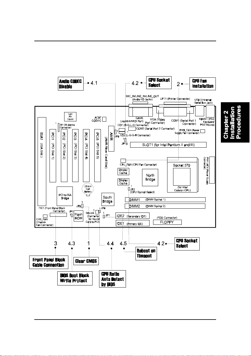
Installation Procedures
2 - 3
Page 18
KW15 Mainboard Manual
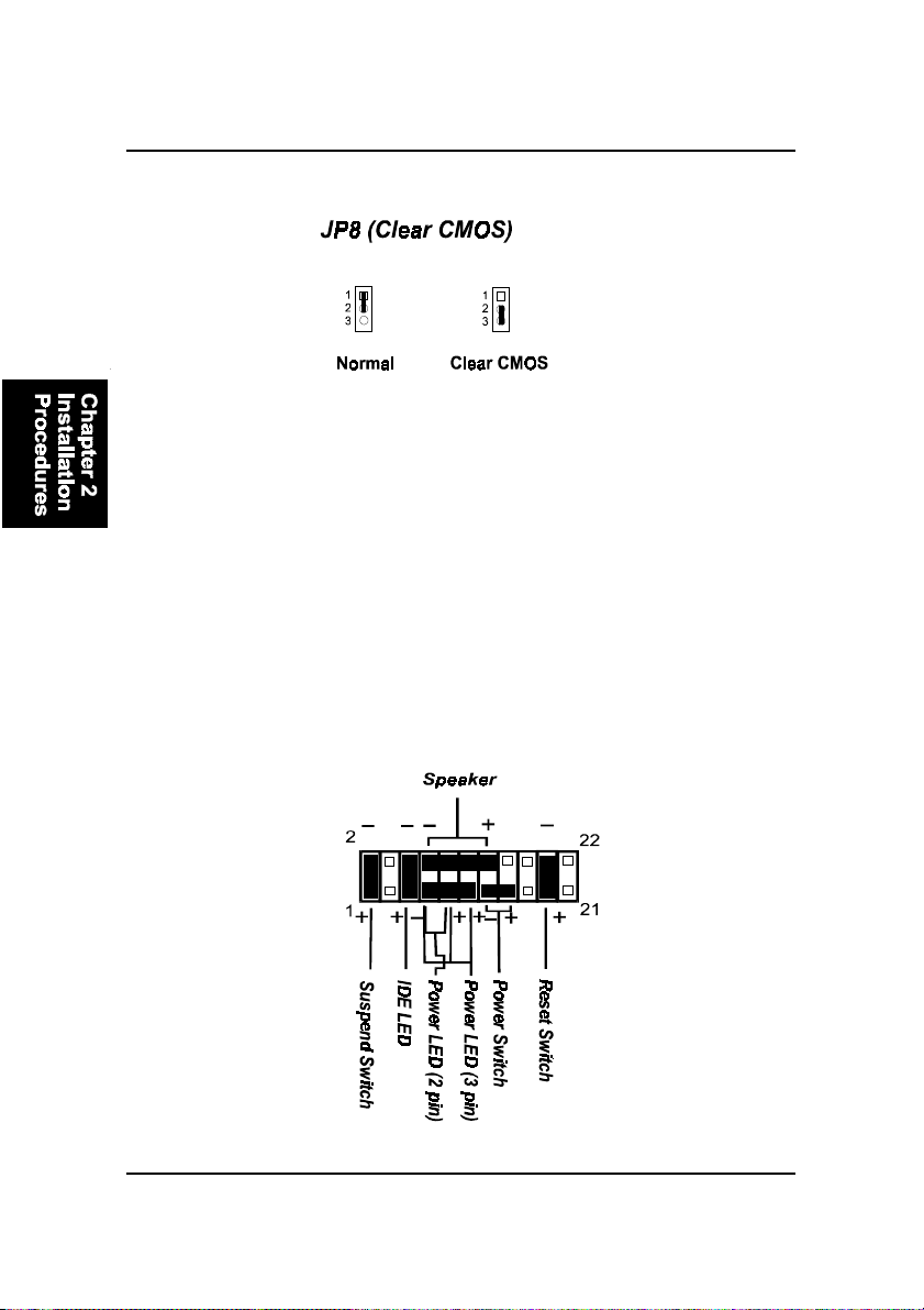
1). Clear CMOS
2). CPU Fan Installation
This connector is linked to the CPU fan. When the system is in suspend mode, the
CPU fan will turn off; when it reverts back to full on mode, the fan will turn back on.
Without sufficient air circulation, the CPU may overheat and cause damage to
both the CPU and the mainboard.
Damage may occur to the mainboard and/or the CPU fan if these pins are
incorrectly used. These are not jumpers, do not place jumper caps over these
pins.
3). Front Panel Block Cable Connection
2 - 4
Page 19
Installation Procedures
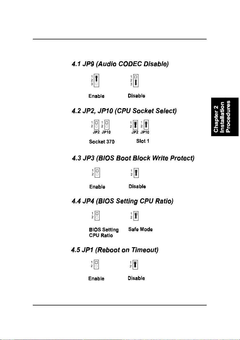
4). Other Enabled/Disabled Jumpers
2 - 5
Page 20

KW15 Mainboard Manual
5). Load BIOS Setup Default
Load Fail-Safe Defaults
BIOS defaults contain the most appropriate values of the system parameters
that allow minimum system performance. The OEM manufacturer may change
the defaults through MODBIN.EXE before the binary image burns into the
ROM.
Load Optimized Defaults (recommended)
Selecting this field loads the factory defaults for BIOS and Chipset Features
which the system automatically detects.
6). How to Upgrade BIOS
1 . Format a bootable system floppy diskette by typing the command format
a:/s in command mode.
2 . Visit the the web site of the vendor and visit the BIOS Update page in the
related T echnical Support section.
3. Select the BIOS file you need and download it to your bootable floppy
diskette.
4. The CD-Pro contained in the package with this mainboard provides the
flash utility in the subdirectory: \utility\flash. (If your BIOS is A ward, the
subdirectory \utility\flash\Award. If BIOS is AMI, the subdirectory
\utility\flash\AMI.) You need to copy the flash tool to the bootable diskette.
5 . Insert the bootable diskette containing the BIOS file into the floppy dis-
kette drive.
6 . Assuming that the floppy diskette drive is A, reboot the system by using
the A: drive. At the A: > prompt, run the BIOS upgraded file by executing
the Flash BIOS utility and the BIOS file with its appropriate extension.
Do not turn off or reset the computer during the flash process or there will be
a problem booting up your system.
2 - 6
Page 21
Installation Procedures
CPU Installation
The mainboard has built-in Switching Voltage Regulator to support CPU Vcore
autodetection. That is, It has the ability to detect and recognize the CPU
voltage, clock, ratio and enables users to set up the CPU frequency from the
BIOS Setup Screen. Users can adjust the frequency through “Frequency /
Voltage Control” of the BIOS Setup Screen.
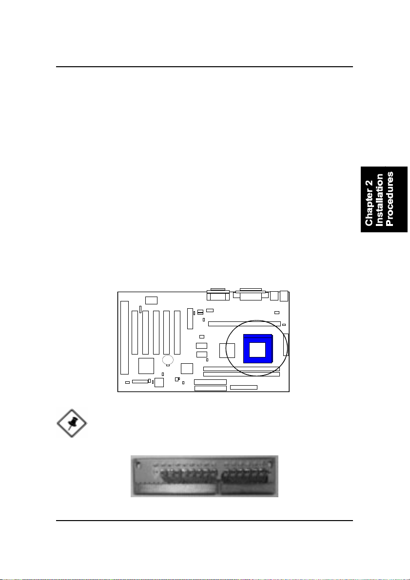
Socket 370
T o install the CPU, do the following:
1 . Lift the lever on the side of the CPU socket.
2. Handle the chip by its edges and try not to touch any of the pins.
3 . Place the CPU in the socket. The chip has a notch to correctly locate the
chip. Align the notch with pin one of the socket. Pin one is located in the
blank triangular area. Do not force the chip. The CPU should slide easily
into the socket.
4 . Swing the lever to the down position to lock the CPU in place.
5 . Place the cooling fan with heatsink on top of the installed CPU.
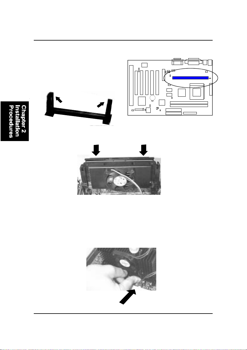
NOTE: A terminal board (see the picture below) comes with your
mainboard KW15. It should be installed on your mainboard Slot1
when you use a Intel FC-PGA (Coppermine) CPU.
2 - 7
Page 22
KW15 Mainboard Manual
SLOT1
1. Pull the two sets of the Retention
Mechanism Assembly upward to the
right position.
2. Insert he CPU module onto the SLOT1 along the Retention Mechanism
|||||||Assembly.
3. Pull the buttons outwards until they click to the right positions.
4. Hook the Heatsink T op Support to the Heatsink Support Base to af fix the
| CPU module.
2 - 8
Page 23
Installation Procedures
System Memory Installation
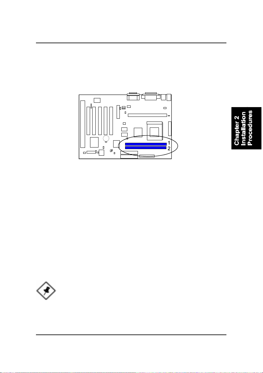
The mainboard provides two 3.3V 168-pin DIMM sockets for system memory
expansion from 8MB to 512MB SDRAM.
Bank/DIMM PC-100 Memory Module Total Memory
Bank0/DIMM1 8/16/32/64/128/256MB 8MB~256MB
Bank1/DIMM2 8/16/32/64/128/256MB 8MB~256MB
Total System Memory 8MB~512MB
DIMM Type, Size, Parity Supported
PC-66/100 or higher performance memory module.
Both parity or non-parity are available.
3.3V, single/double-side.
8/16/32/64/128/256Mbytes.
NOTE: For either 66MHz , 100MHz and 133MHz host bus CPUs,
please use 10ns or faster and PC-100 compliant modules .
2 - 9
Page 24
KW15 Mainboard Manual
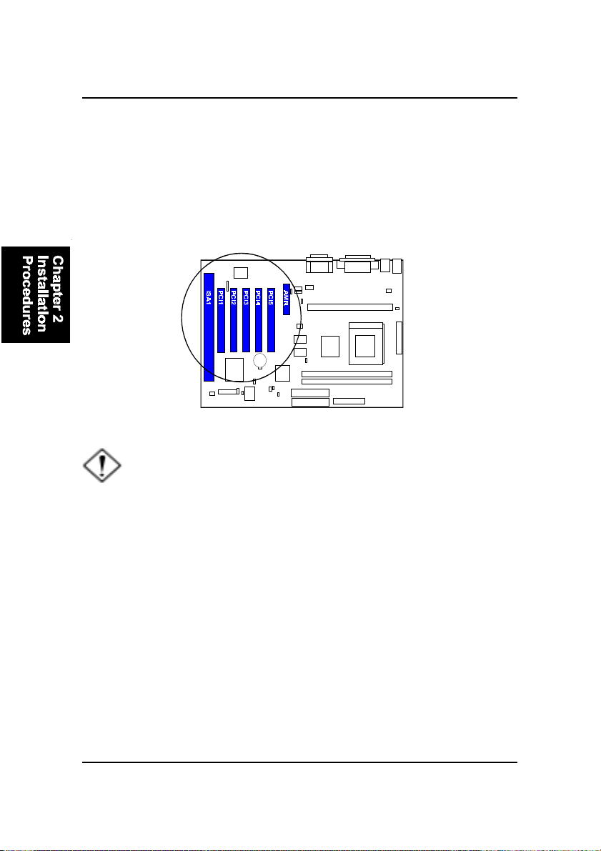
Expansion Cards Installation
This section describes how to connect an expansion card to one of your
system’s expansion slots. Expansion cards are printed circuit boards that,
when connected to the mainboard, increase the capabilities of your system.
For example, expansion cards can provide video and sound capabilities. The
mainboard features five PCI bus expansion slots, one ISA bus expansion slot,
and one AMR slot for your MR modem riser card.
CAUTION: Make sure to unplug the power supply when adding or
removing expansion cards or other system components. Failure to
do so may cause severe damage to both the mainboard and
expansioncards.
Always observe static electricity precautions.
Please read “Handling Precautions” at the start of this manual.
T o install an expansion card, follow the steps below:
1. Remove the computer chassis cover and select an empty expansion
slot.
2. Remove the corresponding slot cover from the computer chassis.
Unscrew the mounting screw that secures the slot cover and pull
the slot cover out from the computer chassis. Keep the slot cover
mounting screw nearby.
2 - 10
Page 25

Installation Procedures
3 . Holding the edge of the peripheral card, carefully align the edge
connector with the expansion slot.
4. Push the card firmly into the slot. Push down on one end of the
expansion card, then the other. Use this “rocking” motion until the
add–on card is firmly seated inside the expansion slot.
5. Secure the board with the mounting screw removed in Step 2. Make
sure that the card has been placed evenly and completely into the
expansion slot.
6 . Replace the computer system’s cover .
7 . Setup the BIOS if necessary.
8. Install the necessary software drivers for the expansion card.
2 - 11
Page 26
KW15 Mainboard Manual
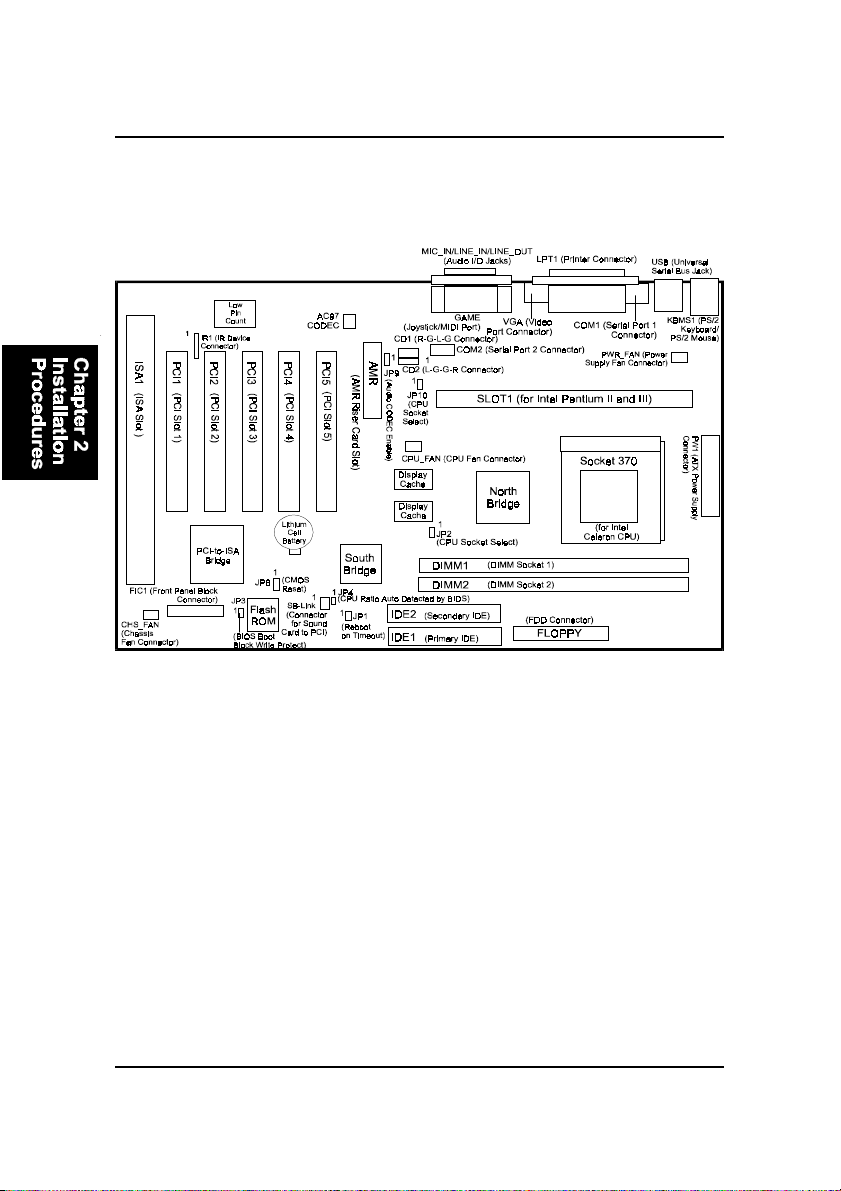
Mainboard Layout
2 - 12
Page 27

Installation Procedures
ONBOARD MARK MEANING P AGE
Jumpers
JP 8 Clear CMOS Data 2 - 15
JP 9 Audio CODEC Enable 2 - 15
JP2, JP10 CPU Socket Type Select 2 - 16
JP 3 BIOS Top Block Lock Select 2 - 16
JP1 Reboot on Timeout 2 - 16
JP 4 BIOS Setting CPU Ratio 2 - 17
Slots
DIMM1/2 DIMM Memory Module Support 2 - 9
PGA370 Celeron CPU Socket 2 - 7
SLOT1 Pentium II/III Socket 2 - 8
AMR Audio Modem Riser Card Slot 2 - 10
ISA ISA Bus Expansion Slot 2 - 10
PCI1/2/3/4/5 PCI Bus Expansion Slot 2 - 10
Connectors
FLOPPY Floppy Diskette Drive Connector 2 - 17
IDE1, IDE2 IDE HDD Device Connectors 2 - 18
SB-LINK PCI Add-on Audio Card Connector 2 - 18
P W1 ATX Power Connector 2 - 19
CPU_FAN CPU Fan Connector 2 - 19
CHS_FAN System Case Fan Connectors 2 - 20
IR1 Infrared Port Module Connector 2 - 20
CD1, CD2 CD Audio-Out Connector 2 - 21
PWR-FAN Power Fan Connector 2 - 21
FIC1 Connectors for Front Panel LEDs
and Switches on Front Panel 2 - 22
VGA VGA Connector 2 - 23
KBMS1 PS/2 Keyboard and Mouse Connector 2 - 23
USB Universal Serial Bus Connectors 2 - 24
LPT1 Printer Connector 2 - 24
COM1, COM2 Serial Port Connector 2 - 25
GAME Joystick/MIDI Device Connector 2 - 25
LINE_OUT, LINE_IN,
MIC_IN Audio I/O Jacks 2 - 26
2 - 13
Page 28
KW15 Mainboard Manual
System Jumpers
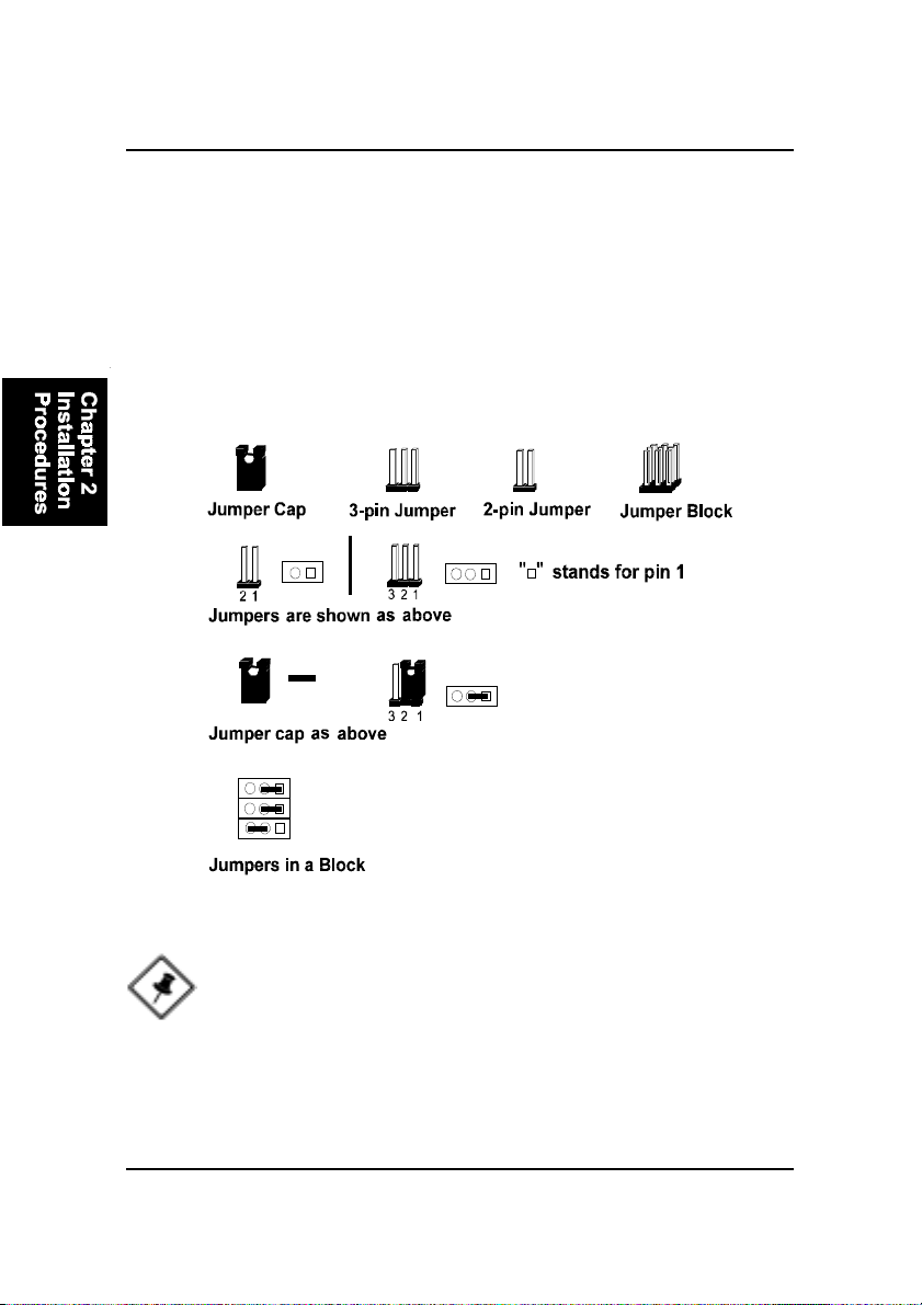
Jumpers are used to select the operation modes for your system. Some jumpers on the board have three metal pins with each pin representing a different
function. A “1” is written besides pin 1 on jumpers with three pins. To set a
jumper, a black cap containing metal contacts is placed over the jumper pin/s
according to the required configuration. A jumper is said to be shorted when
the black cap has been placed on one or two of its pins. The types of jumpers
used in this manual are shown below:
2 - 14
NOTE: Users are not encouraged to change the jumper settings
not listed in this manual. Changing the jumper settings improperly
may adversely affect system performance.
Page 29
Installation Procedures
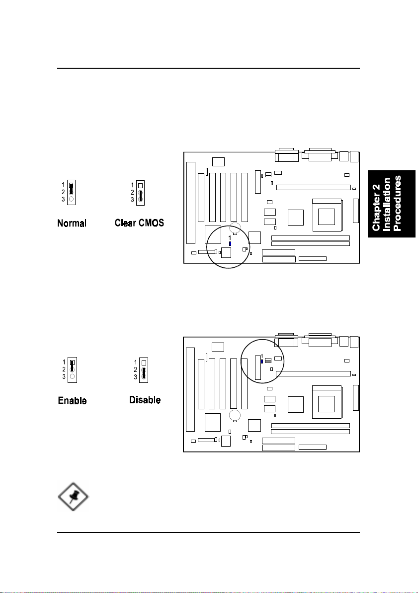
CMOS Clearance Function: JP8
The CMOS RAM is powered by the onboard button cell battery. To clear the
R TC data: (1). Turn off your computer, (2). Move this jumper to Enable, (3).
Move the jumper back to Disable, (4). Turn on your computer , (5). Hold down
the Delete key during boot and enter BIOS Setup to re-enter user preferences.
Audio CODEC Enable: JP9
The jumper allows you to disable the onboard CODEC when you want to
install your sound card.
NOTE: When the function is disabled, only a primary MR modem
card is acceptable on the AMR slot. If the function is enabled, only a
secondary MR modem card is allowed on the AMR slot.
2 - 15
Page 30
KW15 Mainboard Manual
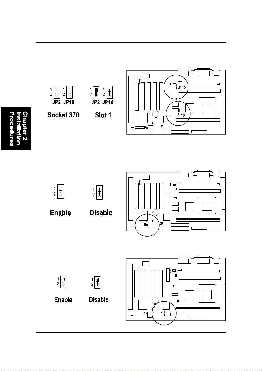
CPU Socket Type Select: JP2, JP10
These two jumpers are to be set in accordance with which CPU socket you are
using.
BIOS Top Block Lock Select: JP3
The 2-pin jumper provides you with the capability to enable the top block of
the BIOS flash ROM while booting ROM needed to reflash. This feature provides protection to the booting area of the BIOS ROM.
Reboot on Timeout: JP1
The mainboard offers the capability to automatically reboot the system after a
period of time if the system fails to boot successfully.
2 - 16
Page 31
Installation Procedures
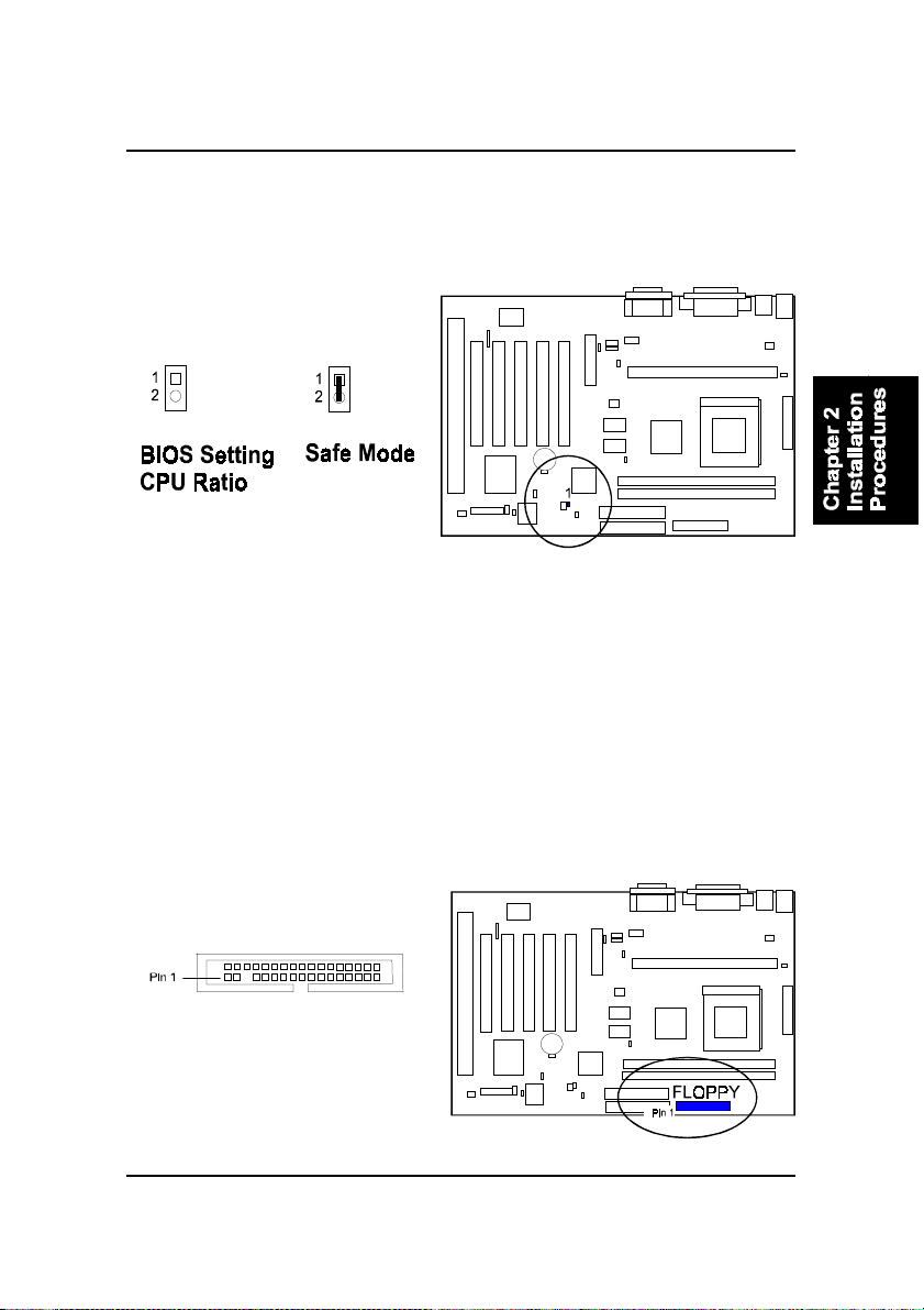
BIOS Setting CPU Ratio: JP4
The 2-pin jumper allows you to use set CPU ratio via BIOS settings. If the
setting is improper and the system can not boot up, please short this jumper
(i.e. Safe Mode) to reboot the system.
Connectors
Floppy Diskette Drive Connector: FLOPPY
This connector provides the connection with your floppy disk drive.
The red stripe of the ribbon cable must be aligned to the same side with the Pin
1.
2 - 17
Page 32
KW15 Mainboard Manual
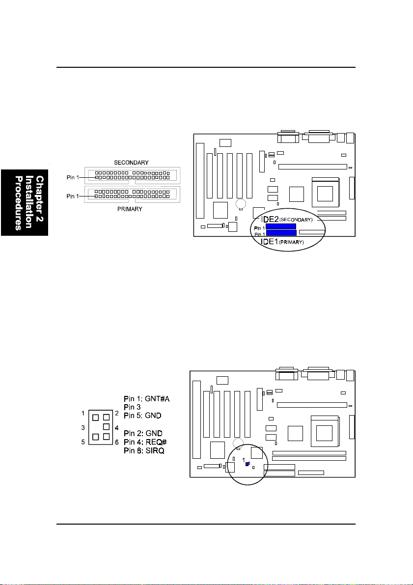
IDE HDD Device Connectors: IDE1, IDE2
These two connectors are used for your IDE hard disk drives, CD drives, LS120|drives, or IDE ZIP drives. The red stripe of the ribbon cable must be
aligned to the same side with the Pin 1.
PCI Add-On Audio Card Connector: SB-LINK
This connector allows you to connect to your PCI add-on audio card connector cable when not using the onboard sound chip.
2 - 18
Page 33
Installation Procedures
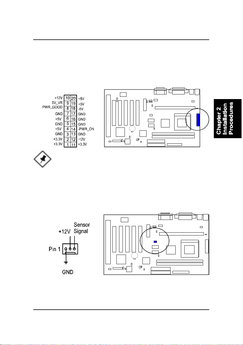
ATX Power Connector: PW1
This 20-pin male block connector is connected to the A TX power supply . The
plug from the power supply will only insert in one orientation because of the
different hole sizes. Find the proper orientation and push down firmly making
sure that the pins are aligned.
NOTE: The power supply must provide +3.3V voltage.
CPU Fan Connector: CPU-FAN
This connector is linked to the CPU fan. When the system is in suspend mode,
the CPU fan will turn off; when it reverts back to full–on mode, the fan will turn
back on. Please refer to the CPU fan installation manual for more information.
2 - 19
Page 34
KW15 Mainboard Manual
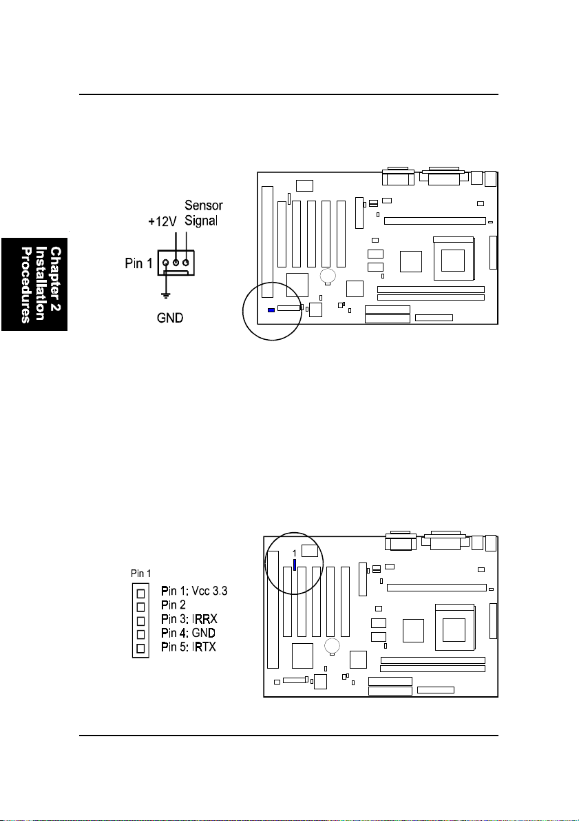
System Case Fan Connector: CHS-FAN
This 3-pin connector links to your cooling fan on the system case to lower the
system temperature.
Infrared Connector: IR1
This 5-pin connector is used to link with your ID device to allow transmission
of data to another system that also supports the IR feature. This module
mounts to a small opening on system cases that support it.
2 - 20
Page 35
Installation Procedures
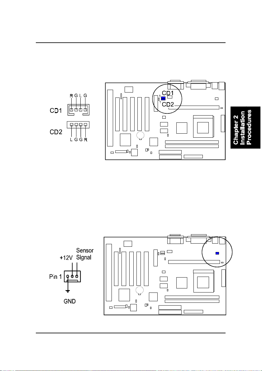
CD Aduio-Out Connectors: CD1, CD2
These two 4-pin connectors are used for different types of the AUDIO-OUT
port of your CD drive.
Power Fan Connector: PWR-FAN
This 3-pin connector is linked with your power supply to control the speed of
cooling fan.
2 - 21
Page 36
KW15 Mainboard Manual
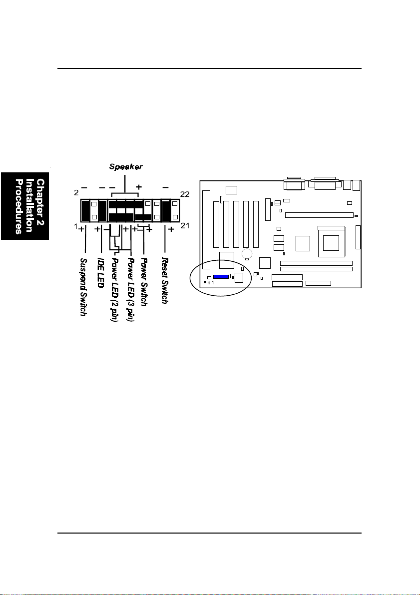
Front Panel Block Connector: FIC1
This block connector concludes the connectors for linking with IDE LED,
power LED, remote power button, message LED, suspend button, reset button and speaker on the front panel of the system case. Please identify polarities of plug wires for the case speaker and LEDs. Please ask vendor about this
information when you buy them and install the system by yourself. The plug
wires’ polarities of these buttons will not affect the function.
Power LED. This is connected with the system power indicator to indicate
whether the system is on/off. It blinks when the system enter the suspend
mode.
Power Switch. This is connected with remote power (soft power) switch. Pusing
this switch will turn the system off and on, instead of turning on the power
supply switch.
Suspend Switch. This is connected with suspend mode switch.
Reset Switch. This is connected to the reset switch. Push this switch to reboot
the system instead of turning the power switch off and on.
Speaker. This is connected with the case speaker.
IDE LED. This is connected to the IDE device indicator. This LED will blink
when the hard disk drives are activated.
2 - 22
Page 37
Installation Procedures
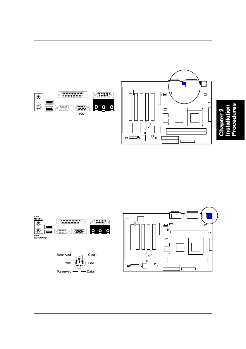
Video Graphics Accelerator Connector: VGA
This 15-pin female D-sub connector is connected to your display monitor.
PS/2 Keyboard and Mouse Connector: KBMS1
These two 6-pin female connectors are used for your PS/2 keyboard and PS/2
mouse.
2 - 23
Page 38
KW15 Mainboard Manual
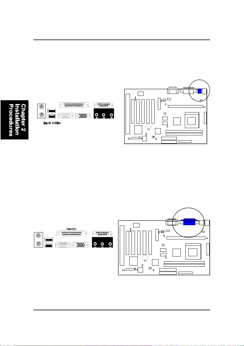
Universal Serial Bus Connectors: USB
These two connectors integrated on the edge of the board are used for linking
with USB peripheral devices. Your operating system must support USB features, such as MS Windows 98, MS Windows 95 OSR2.5 with USB Supplement.
Printer Connector: LPT1
This 25-pin D-Sub female connector is attached to your printer.
2 - 24
Page 39
Installation Procedures
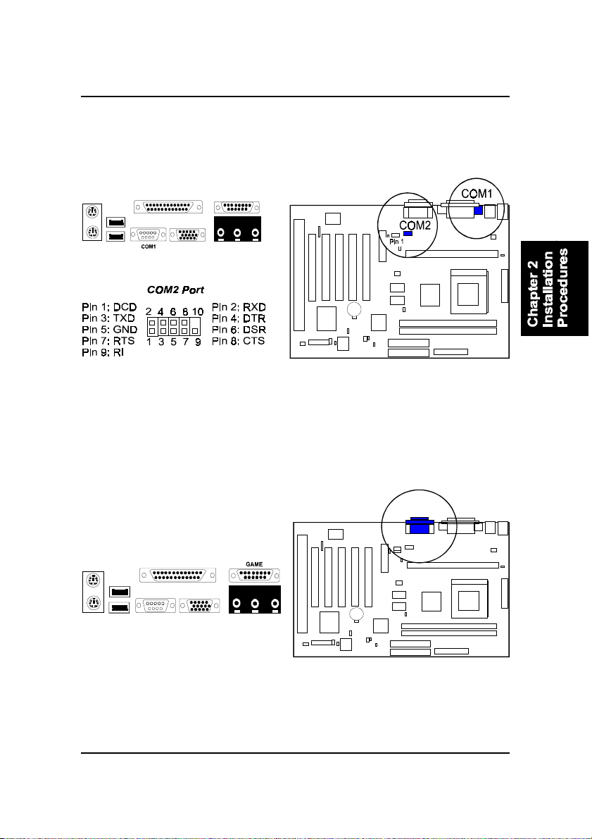
Serial Port Connectors: COM1, COM2
COM1 (9-pin D-sub male connector) and COM2 (9-pin male connector) allow
you to connect with your devices that use serial ports, such as a serial mouse
or an external modem.
Joystick/MIDI Connector: GAME
This 15-pin female connector allows you to connect game joysticks or game
pads for playing games. Connect MIDI devices for playing or editing audio.
2 - 25
Page 40
KW15 Mainboard Manual
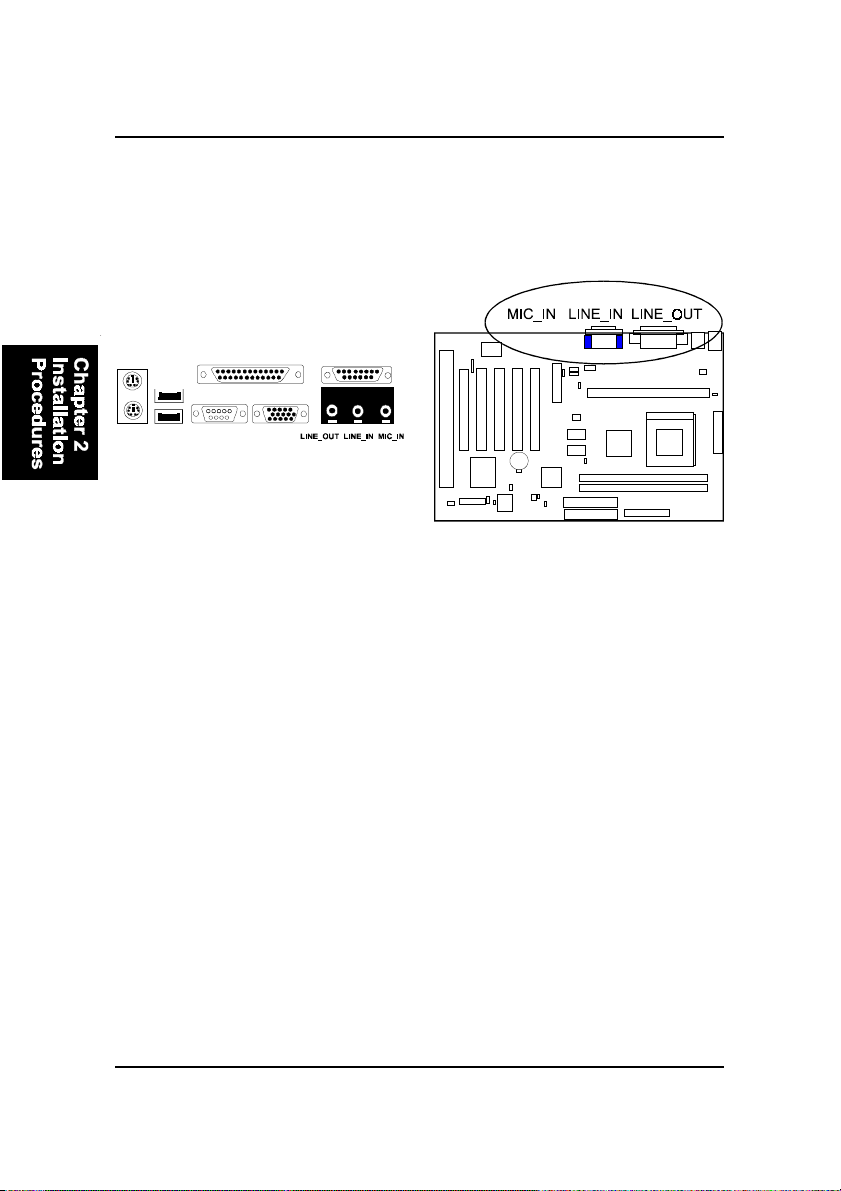
Audio I/O Jacks: LINE_OUT, LINE_IN, MIC_IN
LINE_OUT can be connected to headphones or preferably powered speakers.
LINE_IN allows tape players or other audio sources to be recorded by your
computer or played through the LINE_OUT . MIC_IN allows microphones to
be connected for input voice.
2 - 26
Page 41
BIOS Setup
Chapter 3
BIOS Setup
Award BIOS manufacturer provides access to the system BIOS through the
hardware and software on mainboard. The hardware consists of a Flash ROM
and the software is a group of programs that are installed in the ROMBIOS
along with all the other data that should be included into the BIOS.
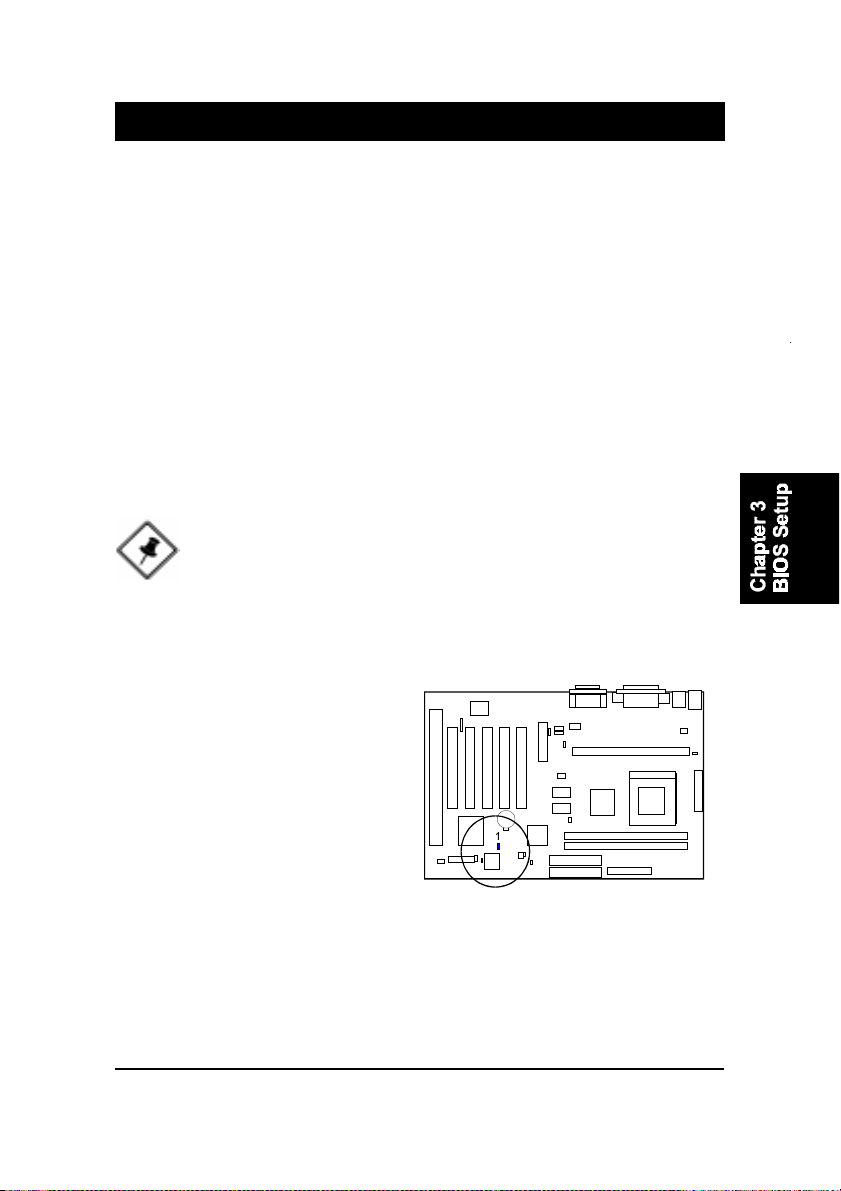
After the BIOS is updated, if you want to clear the old setup data stored in the
CMOS, then you can reset CMOS as follow.
NOTE: In case CMOS should be reset, first unplug the power cord,
then set Jumper 8 2-3 closed for at least 5 seconds, reset JP8 1-2
closed so as to return to normal position and plug the power cord
again.
JP8
Normal 1-2
Reset CMOS 2-3
3 - 1
Page 42
KW15 Mainboard Manual
BIOS Configuration Setup
The mainboard comes with an Award BIOS chip that contains the ROM Setup
information of your system. This chip serves as an interface between the
processor and the rest of the mainboards components. Each feature contains
an introduction to its function for your convenience.
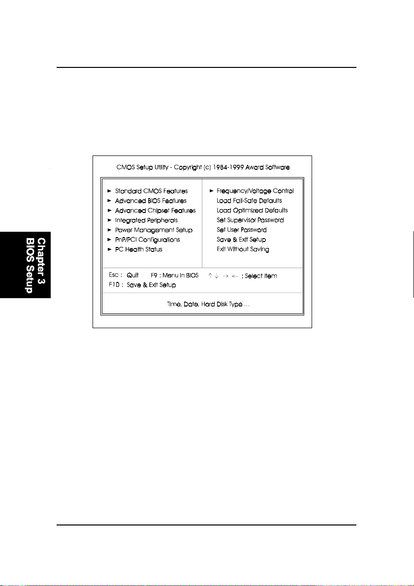
The top-level main setup menu screen is displayed above. Entering each field
that pointed by a triangle head for second-level features by moving highlight
bar by arrow keys to indicate it and then following the Enter key. It allows you
to configure each items if necessary.
Standard CMOS Features allows you to record some basic system hard ware
configuration and set the system clock and error handling. If the mainboard is
already installed in a working system, you will not need to select this option
anymore. However, if the configuation stored in the CMOS memory on the
mainboard gets lost or damaged, or if you change the system hardware con-
figuration, you will need to specify the configuration values. The configura-
tion values usually get lost or corrupted when the power of the onboard
CMOS battery weakens.
3 - 2
Page 43

BIOS Setup
Advanced BIOS Features contains the entries that allows you to improve the
system performance, or lets you set up some system features according to
your preference. Some entries here are required by the boards design to re-
main in their default settings.
Advanced Chipset Features controls the configuration of the mainboards
chipset.
Integrated Peripherals allows you to configure the parameters that your pe-
ripheral devices provided to take advantage of them.
Power Management Setup allows you to reduce the system power consump-
tion. It provides some features for turning off the video display and shutting
down some peripheral devices, such as hard disks, after a specified time pe-
riod.
PnP/PCI Configurations allows you to set up the PCI bus slots. All PCI bus
slots on the system use INTA#, thus all installed PCI adapter cards must be
set to this value.
PC Health Status allows you and technicians to monitor data provided by the
BIOS on this mainboard. Some of them are not user-configurable.
Frequency/Voltage Control allows you to configure the frequency and volt-
age of your processor.
Load Fail-Safe Defaults is for settings that provide a more efficient computer.
If the computer will not boot, select this option and try to diagnose the prob-
lem after the computer boots. These settings do not give optimal performance.
Load Optimal Defaults is selected for settings which provide the best system
performance.
3 - 3
Page 44

KW15 Mainboard Manual
Set Supervisor/User Password
To enable the Supervisor/User passwords, select the item from the Standard
CMOS Setup. You will be prompted to create your own password. Type your
password up to eight characters and press Enter. You will be asked to confirm
the password. Type the password again and press Enter. To disable password,
press Enter twice when you are prompted to enter a password. A message
appears, confirming the password is disabled
Under the BIOS Feature Setup, if Setup is selected under the Security Option
field and the Supervisor/User Password is enabled, you will be prompted
password every time you try to enter the CMOS Setup Utility. If System is
selected and the Supervisor/User Password is enabled, you will be requested
to enter the Password every time when you reboot the system or enter the
CMOS Setup utility.
Save & Exit Setup allows you to write the current settings to CMOS and exit.
Exit Without Saving allows you to exit without writing the current settings to
CMOS.
3 - 4
Page 45

Chapter 4
FAQs
General FAQs
How do I know which version BIOS I have?
Check it on the boot screen, click [Pause/Break] button to give you time to
write it down.
How do I know which FLASH chip I have?
Partially remove the sticker from the chip to check the name of the manu-
facturer. Usually the jumper setting is set correctly in the factory.
How can I get the USB drivers?
Download Microsoft USB Supplement and a set of generic USB Drivers
from Drivers and Utilities Page. You must have Windows 950B (Service
Release II, "Windows97") to install these.These drivers resolve the yellow
exclamation mark problem (Unknown Devices, USB) in Device Manager.
It is recommended to install Windows 98/98 SE; as it provides built-in USB
drivers.
FAQ
What is the DMI utility is used for?
The DMI Configuration Utility can be used to maintain the Management
Information Format Database (MIFD). DMI is also able to auto-detect and
record information pertinent to a computers system such as the CPU type,
CPU speed and internal/external frequencies and memory size. The onboard
BIOS detects as much system information as possible and stores it in a
4KB Block in the motherboards Flash EPROM and allows the DMI to
retrieve data from this database. The DMI utility also allows the system
integrator or end user to add additional information into the MIFD such as
serial numbers, housing configuration and vendor information. This infor-
mation cannot be detected by the motherboards BIOS and has to manu-
ally entered through the DMI Configuration utility and updated into the
MIFD.
4 - 1
Page 46

KW15 Mainboard Manual
How do I use the DMI Utility?
Be very careful in using this utility as your system can become totally
unusable after altering and saving some configurations on DMI. DMI
Utility should not be run from Windows or DOS version higher than v6.22.
If you accidentally alter some settings using DMI Utility under Windows95
(or MS-DOS that comes with it), flash the system BIOS immediately, do not
reboot. We recommended using DOS 6.22 as Win 95 (when applying the
DMI Utility) will sometimes show an insufficient error message, when load-
ing the Flash Utility. In that case, the other option is to use the Boot Block
feature on the BIOS. Use an ISA VGA card for the system to allow them to
boot at least on drive "A" (using DOS 6.22 of course) so you will be able to
flash the BIOS at least. If you use DMI from Windows95 DOS prompt or
Restart in MS-DOS mode, you will not be able to restart the PC.
Where can I get the drivers for PCI set motherboards?
To download the drivers you need, visit the chipset vendor s website
Drivers and Utilities Page. There you will see links to FAQs and other Web
sites that explain in detail how to install the drivers.
Why not update BIOS?
In 90% of cases, a BIOS update is released to address a problem with a
particular piece of hardware or software.Therefore, the new BIOS gives the
system some new (different) parameters to work with. Newer BIOS'es con-
tain all fixes from previous versions. If the fix list of a new BIOS does NOT
address any of problems that you may have, it is unreasonable to update
BIOS only for sake of it, because you may be using a combination of
hardware/software that is incompatible and yet-untested with the BIOS
version you're upgrading to.
It is recommended to refrain from updating BIOS without a good reason. If
you don't see your problem listed in the fix list, do not update BIOS - better
go to a shareware Web site (winfiles.com, shareware.com, tucows.com)
and update your software or do something les dangerous.
4 - 2
Page 47

And finally, some 10% of BIOS updates contain new CPU ID strings and
code enhancements (ACPI, etc.). For those an update is recommended
only when it is necessary (i.e. the processor ID does not display properly,
the system must have ACPI, etc.).
A typical situation occurs when a user wants to update BIOS because the
new version supports a CPU he/she "plans" to buy sometime in the future.
With some bad luck, the user ends up with a wrong BIOS (wrong PCB, or
chipset, or I/O or all of them) and a fried BIOS.
BIOS FAQs
How do I flash a new BIOS?
The mainboard package provides a BIOS flash software tool in the soft-
ware utility CD-ROM. This software feature is provided for upgrading
BIOS use. Play the CD-ROM, click on Browse CD, select Flash, then choose
the BIOS vendor that provided the BIOS this board came with. Please print
the relating README file and read it first. For more information, please
visit FIC Online at www.fic.com.tw.
FAQ
Downloading BIOS File
Format a bootable system diskette, and then visit the FIC website at
www.fic.com.tw. Click BIOS/Drivers Update item under BIOS group, then
select the BIOS file you need. Download it to your bootable diskette.
Upgrading BIOS File
Place the bootable diskette containing the BIOS file in the diskette drive
(Assume the diskette drive is A.), and reboot the system by A drive. At
the A: > prompt, execute the BIOS upgrading procedure by entering the
Flash BIOS utility and the BIOS file with its extension.
Command: {flash tool file}{space}{downloaded BIOS file} <Enter>
The other parameters are listed in the relating README file, please read it
if need.
4 - 3
Page 48

KW15 Mainboard Manual
After press Enter key, type Y to the message Press Y to Continue, N
to Reboot. Press Enter key. When the message Press Any Key to Reboot,
appears the procedure is completed. Press any key to reboot.
What is "Hardware-based intelligent virus protection"?
This is a new BIOS feature based on anti-virus (AV) software that protects
the system from boot-time viruses. It is intellgent in the sense that it uses
rules modeled after viruses behavior. For example, it can tell the difference
between normal writing to HDD boot sector and virus-attempted writing.
It unloads after boot-up so it does not provide total protection and is not
intended to serve as replacement for regular anti-virus software.
This utility includes only Scan Funcition and not Virus Delete function.
There are no virus definition files to update.
When I try to flash the BIOS I get an error message saying there is a
wrong part number. Why?
Flash EPROM ("BIOS") chips used on FIC motherboards vary (Intel, AMD,
Fujitsu, etc.). As far as this problem is concerned, there are two possible
reasons:
a) you may have used a wrong BIOS or flash utility. Verify that both the
BIOS file and the flash utility are the correct versions.
b) the flash utility you used did not recognize the type of flash EPROM
installed on your motherboard. Verify that you have the right files and if
you're sure in that, ignore the warning.
I updated my BIOS and am not satisfied with the result (slower performance, new bugs, etc.). What now?
Restore the old BIOS or wait until a newer BIOS is available. You should
use the flash utility supplied with the old BIOS and NOT the flash utility
you got with the new BIOS. If you do not know what flash utility it was,
consult the Web support pages or contact technical support.
4 - 4
Page 49

Why not update BIOS?
In 90% of cases, a BIOS update is released to address a problem with a
particular piece of hardware or software.Therefore, the new BIOS gives the
system some new (different) parameters to work with. Newer BIOS'es con-
tain all fixes from previous versions. If the fix list of a new BIOS does NOT
address any of problems that you may have, it is unreasonable to update
BIOS only for sake of it, because you may be using a combination of
hardware/software that is incompatible and yet-untested with the BIOS
version you're upgrading to.
It is recommended to refrain from updating BIOS without a good reason. If
you don't see your problem listed in the fix list, do not update BIOS. It is
better go to a shareware Web site (winfiles.com, shareware.com,
tucows.com) and update your software.
And finally, some 10% of BIOS updates contain new CPU ID strings and
code enhancements (ACPI, etc.). For those an update is recommended
only when it is necessary (i.e. the processor ID does not display properly,
the system must have ACPI, etc.).
A typical situation occurs when a user wants to update BIOS because the
new version supports a CPU he/she "plans" to buy sometime in the future.
With some bad luck, the user ends up with a wrong BIOS (wrong PCB, or
chipset, or I/O or all of them) and a destroged BIOS.
FAQ
Windows 98/98 SE FAQs
What is the correct installation procedure for VIA-based motherboards?
There are four steps:
1) Install Win98/98 SE on your system
2) Install the patch files and other drivers that are contained in the CD-Pro
3) Install your add-on card drivers
NOTE: If your visual performance became unstable after the above
installation was completed (especially if a VGA card driver was
installed in Step 3), please execute Step 2 again. It should solve
the problem. This is possible as most probably the driver version
of the add-on card is earlier than that of the patch files and drivers
contained in the CD-Pro.
4 - 5
Page 50

KW15 Mainboard Manual
Windows 95 FAQs
What is the proper install order of graphics-related VIA drivers?
1)Install Windows, 2) If your motherboard has an AGP port, load Vxd
driver v. 2.9. 4) Load display card driver.
Why does my VIA chipset-based system crash when the system attempts to access the UDMA HDD?
This problem occurs under Windows 95 OSR2 and OSR 2.1. Please down-
load them at
http://support.microsoft.com/support/kb/articles/q171/3/53.asp
How can I know if a software (example: WindowsNT) is compatible with
FIC motherboards?
Each FIC motherboard is tested with a variety of operating systems and
applications. Compatibility reports are published every time new or up-
dated models of a motherboard are released.Compatibility reports can be
downloaded from individual motherboard support pages or from the FIC
FTP Server (opens in a new window).
Windows95 shows an exclamation mark next to USB device on my
motherboard. Is there any driver that canhelp me?
The reason you can see that Exclamation mark on USB serial Bus & PCI
Bridge is that Windows95 doesnot support it. You will need to install the
drivers to fix it.
4 - 6
 Loading...