

Page 1

Mainboard
User Guide
1
Page 2

Mainboard User Guide
Table of Contents
Cha pter 1 Main Features
....................................................................................................... 3
Chapter 2 Installation Procedures
1). Set System Jumpers .................................................................. 6
Clear CMOS ...................................................................... 6
BIOS Protect...................................................................... 7
2). Install Memory Modules .......................................................... 9
3). Install the CPU .......................................................................... 10
Connect A TX Power.......................................................... 11
4). Install Expa nsion Cards............................................................. 12
5). Connect Devices ....................................................................... 13
Floppy Diskette Drive Connector ...................................... 13
IDE Device Connectors ..................................................... 14
Power Connectors ............................................................. 14
Front Pa nel Block .............................................................. 15
CD Audio-In Connectors................................................... 16
SPDIF Out Connector ....................................................... 17
Serial IRQ Connector......................................................... 17
Chassis Intrusion Connector ............................................ 18
Fan Connectors ................................................................. 18
Serial A TA Connectors ...................................................... 19
PS/2 Keyboard and Mouse Connector.............................. 19
Printer Connector .............................................................. 20
Universal Serial Bus Connectors....................................... 21
IEEE 1394 Connector (optional)....................................... 21
Serial Port Connector ........................................................ 22
Audio I/O Jacks ................................................................ 23
Front Audio Connector ..................................................... 23
V GA Connector . .................................................................... 24
RJ 45 Connector . .................................................................. 24
2
Page 3

Cha pter 3 BIOS Setup
CMOS Setup Utility ....................................................................... 24
Sta ndard CMOS Setup................................................................... 25
Advanced BIOS Features .............................................................. 27
Advanced Chipset Features .......................................................... 29
Integrated Peripherals.................................................................... 30
Power Management Setup ............................................................. 32
PC Health Status ............................................................................ 33
Load Opti mized Defaults ................................................................ 34
Supervisor/User Password ............................................................ 34
Save a nd Exit Setup........................................................................ 34
Exit without Saving ........................................................................ 34
3
Page 4

Mainboard User Guide
Main Features
CPU
Duron: 1.6 - 1.8 GHz at FSB 266 MHz
Athlon XP:
Palomino Core: 1500+ - 2100+ at FSB 266 MHz
Thoroughbred Core: 1700+ - 2700+ at FSB 266/333 MHz
Barton Core: 2500+ - 3200+ at FSB 333 MHz
2500+ - 3200+ at FSB 400 MHz
Sempron: 3000 + a nd up
Chipset
North Bridge: nV idia nForce 2 IGP-S
South Bridge: nV idi a nForce 2 MCP-S
Memory
2 Memory Sockets:
Support DD R 266/333/400
T otal Memory Size up to 2 GBs
Expa nsion Slots
AGP Slot: Support AGP V3.0 32bit / 66MHz 4X/8X
3 PCI Slots: Support PCI V2.2 32bit / 33MHz
IDE Connections
2 IDE Connectors - PIO Mode, Ultra DMA 66/100/133
Up to 4 Devices
SAT A Connections (Optional)
2 Serial-ATA Connectors, Support 2 Device s.
4
Page 5

Audio Features
ALC 655 (5.1 Cha nnel Audio)
AC97 V2.3 complia nt
LINE_IN, LINE_OUT, MIC_IN Jack
Front Audio Pinheaders
I/O Ports
1 Serial Port
1 V GA Port
1 Floppy Connector
1 Parallel Port
PS/2 Mouse a nd PS/2 Keyboard
8 USB Ports
LAN
IEEE802.3 nVidi a 10/100 Mbps Fa st Ethernet.
Mounting Holes
6 Holes
Mainboard Size
9.0 x 9.6 (unit: inch)
IEEE 1394 Ports (optional)
VT6307L
2 IEEE 1394 ports
1 Bracket with Ca ble
5
Page 6

Mainboard User Guide
Chapter 2
Installation Procedures
The mainboard has several user-adjustable jumpers on the board that allow you to
configure your system to suit your requirements. This chapter contains information
on the various jumper settings on your mainboard.
To set up your computer, you must complete the following steps:
Step 1 - Set system jumpers
Step 2 - Install memory modules
Step 3 - Install the Central Processing Unit (CPU)
Step 4 - Install expansion cards
Step 5 - Connect ribbon cables, cabinet wires, and power supply
Step 6 - Set up BIOS software
Step 7 - Install supporting software tools
WARNING: Excessive torque may damage the mainboard. When
using an electric screwdriver on the mainboard, make sure that
the torque is set to the allowable range of 5.0 ~ 8.0kg/cm.
Mainboard components contain very delicate Integrated Circuit
(IC) chips. To prevent static electricity from harming any of the
sensitive components, you should follow the following precautions whenever working on the computer:
1. Unplug the computer when working on the inside.
2. Hold components by the edges and try not to touch the IC
||||chips, leads, or circuitry.
3. Wear an anti-static wrist strap which fits around the wrist.
4. Place components on a grounded anti-static pad or on the bag
that came with the component whenever the components are
separated from the system.
6
Page 7

1.) Set System Jumpers
Jumpers are used to select the operation modes for your system. Some jumpers on the board have three metal pins with each pin representing a different
function. A 1 is written besides pin 1 on jumpers with three pins. To set a
jumper, a black cap containing metal contacts is placed over the jumper pin(s)
according to the required configuration. A jumper is said to be shorted when
the black cap has been placed on one or two of its pins.
NOTE: Users are not encouraged to change to jumper settings not
listed in this manual. Changing the jumper settings improperly may
adversely affect system performance.
Clear CMOS
The CMOS RAM is powered by the onboard button cell battery.
T o clear the RTC data:
(1) Turn off your computer;
(2) Open the system case and disconnect the AC power cord;
(3) Place the jumper cap onto the pinpair 2-3 for at least 6 seconds
to clear CMOS data;
(4) Place the jumper cap onto the pinpair 1-2 to normal operation;
(5) Close the system case and connect the AC power cord;
(6) Turn on your computer until CMOS checksum error appears;
(7) Press the Delete key as it boots;
(8) Enter the BIOS Setup to re-enter user preferences.
7
Page 8

Mainboard User Guide
BIOS Write Protect(Optional)
The jumper helps to prevent the boot block table area in the BIOS ROM
from being overwritten by mistake.
8
Page 9

2). Install Memory Modules
1. Locate DD R DIMM sockets
on the mainboard.
2. Install DDR DIMM straight
down into the socket 1 using both
hands, then socket 2, and so forth.
3. The clip on both ends of the
socket will close up to hold the
DDR DIMM in pla ce when the DD R
DIMM reaches the socket bottom.
9
Page 10

Mainboard User Guide
3). Install the CPU
The mainboard has a built-in Switching Voltage Regulator to support CPU
Vcore autodetection. That is, it has the ability to detect a nd recognize the CPU
voltage, clock, ratio. Users ca n view the report about CPU frequency through
Frequency / Voltage Control on the BIOS Setup Screen.
CAUTION:
1. The heat sink and fan you installed must be approved by AMD.
2. The mainboard must be placed on a solid surface to avoid shak
ing while install the heat sink and fan are installed on the board.
3. The heat sink must make tight contact with the CPU top.
4. Never run the processor without the he at sink properly and firmly
attached. PERMANENT DAMAGE WILL RESULT!
The procedures below shows you how to install your CPU and its fan
a nd heatsink. First of all, locate the CPU socket on the mainboard.
1. Swing the lever upward to 90 degree.
2. Install the CPU, making sure of the pin 1
orientation by aligning the socket corner marking
with the socket corner closest to the lever tip.
Do not insert the CPU by force. Make sure the
processor is fully inserted into the socket on all
sides.
Affix the CPU by pressing the lever downward
and locking it beside the socket.
10
Page 11

3. Place the fa n with heatsink on the CPU top
and press down on the two plastic clips,
hooking them up with the holes on the two
sides of the retention module.
4. Press the white bar on each clip down to
fasten the fan set on the retention module.
Connect ATX Power
The 20-hole power plug (1st figure) is connected to the ATX power 20-pin
pinheaders. The 4-hole 12V power plug (2nd figure) is inserted in the ATX_12V
power connector.
The plug from the power supply can only be inserted in one orientation
because of the different hole sizes. Find the proper orientation and push down
firmly making sure that the pins are aligned.
11
Page 12

Mainboard User Guide
4). Install Expansion Cards
This section describes how to connect an expansion card to one of your
system expansion slots. Expa nsion cards are printed circuit boards that, when
connected to the mainboard, increase the capabilities of your system. For
example, expansion cards can provide video and sound capabilities. The
mainboard features one AGP and three PCI bus expa nsion slots.
CAUTION:
1.Make sure to unplug the power supply when adding or remov
ing expansion cards or other system components. Failure to
do so may cause severe damage to both the mainboard and
expansion cards.
2.Always observe static electricity precautions.
3.Please read Handling Precautions at the start of this manual.
1. Select an availa ble expansion slot.
2. Remove the corresponding slot cover from the computer chassis. Un-
screw the mounting screw that secures the slot cover and pull the slot cover
out from the computer chassis. Keep the slot cover mounting screw nearby.
12
Page 13

3. Push the card firmly into the slot.
Push down on one end of the expansion card, then the other. Use this rocking motion until them card is firmly
seated inside the expansion slot. Secure the card with the screw removed
in Step 2.
5). Connect Devices
Floppy Diskette Drive Connector
This connector provides the connection
with your floppy disk drive.
Insert the floppy ribbon cable
(below) onto the floppy connector.
The colored stripe (indicated by the
arrow head, right) of the ribbon cable
must be the same side as Pin 1.
13
Page 14

Mainboard User Guide
A
A
IDE Device Connectors
The two connectors, IDE1 (PRIMARY)
a nd IDE2 (SECONDARY), are used f or
your IDE hard disk drives, CD drives,
LS-120|drives, or IDE ZIP drives.
Insert the floppy ribbon cable
(below) onto the floppy connector.
The colored stripe (indicated by the
arrow head, right) of the ribbon cable
must be the same side as Pin 1.
Power Connectors
The 20-pin male block connector is connected to the ATX power supply. The
4-pin male block connector is for the ATX_12V power supply. Both connectors are linked with your ATX power supply. The plug from the power supply
ca n only be inserted in one orientation because of the diff erent hole sizes. Find
the proper orientation and push down firmly making sure that the pins are
aligned.
TX_12V
+12V
+12V
PIN DEFINITION PIN DEFINITION
1
2
3
4
5
6
7
8
9
10
Pin1 Pin10
GND
GND
Pin11
+3.3V
+3.3V
GND
+5V
GND
+5V
GND
PWR_GOOD
5V_SB
+12V
11
12
13
14
15
16
17
18
19
20
14
TX_PWR
+3.3V
-12V
GND
PS_ON
GND
GND
GND
-5V
+5V
+5V
Pin20
Page 15

Front Panel Block
This block connector includes the connectors for linking with Power LED (3pin), HDD LED, power button, power/slee p/me ssage waiting button, and the
reset button on the front panel of the system case. Please identify the polarities of the plug wires for the case speaker and LEDs.
The plug wires (below) polarities
of these buttons will not affect
the function.
(1) Reset Switch is connected to the reset button. Push this switch to reboot
the system instead of turning the power button off and on.
(2) HDD LED is connected to the IDE device indicator. This LED will blink
(3) Power (Single a nd Dual) /Sleep LED
Please refer to the ta ble s below for the re presentations of LED states.
There is a nother 3-Pin Power LED connector on
board for some cases that have a 3-pin plug.
(4) Power Button is connected with the power button. Pushing this switch
allows the system to be turned on and off rather than using the power supply
button.
15
Page 16

Mainboard User Guide
R
IR is a pinheader that is used f or
linking with your IR device to
allow transmission of data to
another system that also supports the IR feature.
I
(optional)
SPK
(Speaker)
+5V
IRRX
GND
IRTX
+5V
GND
GND
Signal
Speaker is connected with the
case speaker.
NOTE: To use IR functions you must adjust the BIOS fe ature s introduced in the section of Integrated Peripherals, Chapter 3, for your
IR devices.
CD Audio-In Connectors
The connectors, CD_IN and AUX_IN, are for CD-ROM drive audio analog
input use. The pin assignment are: Pin 1 is Left, Pin2 and 3 are GND, Pin 4 is
Right.
CAUTION: Improper orientation of SPDIF connection may cause
damage of your device.
16
Page 17

SPDIF Out Connector (Optional)
Serial IRQ Connector(Optional)
This 2-pin connector is used for some system integration use.
Pin 1 is Serial IRQ signal, Pin 2 is GND.
17
Page 18

Mainboard User Guide
Chassis Intrusion Connector (optional)
This connector is for a chassis
designed with intrusion detection feature. It needs a chassis
intrusion sensoror on the
chassis. If a chassis part is
moved, the sensor activates and
releases a signal in order to this
connector to record a chassis intrusion event. Pin1 is +5V
Standby, Pin2 is intrusion signal,
Pin3 is GND.
Fan Connectors
The CPU_F AN connector is f or CPU heatsink a nd cooling fan. The SYS_FAN
connector is for system fan on the case. CPU_FAN is Smart Fan controlled.
The fa n speed de pends on CPU te mpurature. PWR_FAN can be used with the
power supply cooling fa n. Pin1 is GND, Pin2 is +12V , Pin3 is Fa n Speed Signal.
18
Page 19

Serial ATA Connectors (Optional)
The 2 SATA connectors provide you with the connections to Serial ATA
devices that confirm to the Serial ATA specification. Serial ATA supports all
ATA and ATAPI devices. The figure s below left are two SAT A ca ble s (the top
one is for power; the next one is for data). The data cable pin assignments of
SATA connector.
NOTE: To use SATA functions must adjust BIOS fe atures introduced
in the section of Integrated Peripherals, Chapter 3, for your SATA
devices.
PS/2 Keyboard and Mouse Connector
These two 6-pin female connectors are used for your PS/2 keyboard and PS/2
mouse. PS/2 keyboard is purple color a nd PS/2 mouse is green color
19
Page 20

Mainboard User Guide
Printer Connector
This burgundy colored 25-pin D-Sub female connector is attached to your
printer.
20
Page 21

Universal Serial Bus Connectors
The mainbaord has 8 USB ports; 4 USB black jacks that are integrated on the
edge of the board, the other 4 USB pinheaders are on the board. They allow to
attach to USB devices either from the rear or front panels. The USB cable that
comes with your mainboard is used to connecting between the USB pinheaders
and rear panel. (See the photo below).
The figure at right shows the pin assignments of the USB5/6.
Those of USB6/7 are similar.
+5V
USB5USB5+
GND
+5V
2
1
USB6-
4
3
USB6+
6
5
GND
8
7
10
NC
PIN DEFINITION
+5V
1
+5V
2
USB5-
3
USB6-
4
USB5+
5
USB6+
6
GND
7
GND
8
Key
9
N.C
10
IEEE 1394 Connector (optional)
The mainbaord has 2 1394 ports; 1 1394 black jack that is integrated on the
edge of the board, another 1394 pinheader is on the board. They allow to
attach to 1394 devices either from the rear or front panels. The 1394 cable that
comes with your mainboard is used to connecting between the 1394 pinheader
a nd rear panel.
21
Page 22

Mainboard User Guide
The 2 optional 1394 pinheaders on the board provides you with two connections with the peripherals which own 1394 connectors by an optional bra cket
with cable (see the figure below). The pin definitions of the 1394 pinheaders
are listed below also.
Serial Port Connector
COM1
This teal colored 9-pin D-sub male connector allows you to connect with your
device that use a serial port, such a s a serial mouse or a n external modem.
COM2 (optional)
This pin header allows you to connect your serial port devices via the bra cket
cable (see the figure below)
22
Page 23

Audio I/O Jacks
LINE_OUT (lime) can be connected to headphones or preferably powered
speakers. LINE_IN (light blue) allows tape players or other audio sources to
be recorded by your computer or played through the LINE_OUT. MIC_IN
(pink) allows microphones to be connected for audio input.
NOTE: LINE_IN, LINE_OUT, and MICROPHONE jacks ca n be used
the 5.1-channel audio output with its software tool.
Front Audio Connector
The mainboard has a front panel audio F_AUDIO connector . It allows users to
attach the audio device via the front panel (instead of the rear panel) by a
ribbon cable that in some cases.
Its pin definitions are resented below.
NOTE: If you do not use F_AUDIO, please keep the pinpair 5-6, 9-10
short as default; also, when the front headphone is plugged in,
the rear audio output will be disabled.
23
Page 24

Mainboard User Guide
VGA Connector
This connector is linked to your monitor. The pin
assignments are shown at right side.
RJ45 LAN Connector
The RJ45 jack of the LAN port is used f or the LAN cable plug.
24
Page 25

Chapter 3
Chapter 3
BIOS Setup
The mainboard comes with a chip from Award BIOS that contains the ROM
Setup information for your system. This chip serves as an interface between
the processor and the rest of the mainboard components. This section explains the information contained in the Setup program and tells you how to
modify the settings according to your system configuration.
CMOS Setup Utility
The Setup Utility program allows updates to the mainboard configuration
settings. The BIOS setup values will be saved in the CMOS. Setup is executed
when the user changes system configurations; changes the system backup
battery or the system detects a configuration error and asks the user to run the
Setup program. Use the arrow keys to select and press Enter to run the selected program.
25
Page 26

Mainboard User Guide
Standard CMOS Setup
The Standard CMOS Setup screen is displayed above. Each item may have
one or more option settings. The system BIOS automatically detects memory
size, thus no changes are necessary. Use the arrow keys to highlight the item
a nd then use PgUp or PgDn keys to select the value you want in each item.
Date
T o set the date, highlight the Date field a nd then press Page Up/Page Down
or +/- keys to set the current date. Follow the month, day and year format.
Time
T o set the ti me, highlight the T ime field a nd then press Page Up/Page Down
or +/- keys to set the current time. Follow the hour, minute, and second
format.
26
Page 27

Hard Disks
This field records the specifications for all non-SCSI hard drives installed
in the system. The onboard PCI IDE connectors provide Pri mary and Secondary channels for connecting up to four IDE hard disks or other IDE
devices. Each channel can support up to two hard disks, the first of which
is the Master and the second is the Slave.
Hard Disk Configurations
Capacity: The hard disk size. The unit is Bytes.
Cylinder: The cylinder number of the hard disk.
Head: The read/write head number at the hard disk.
Precomp: The cylinder number of which the disk drivechanges the
write current.
Landing Zone: The cylinder number on which the disk drive heads
(read/write) are seated when the disk drive is parked.
Sector: The sector number of each track defined on the hard
disk.
Halt On
This field determines which types of errors will cause the system to halt.
27
Page 28
Mainboard User Guide
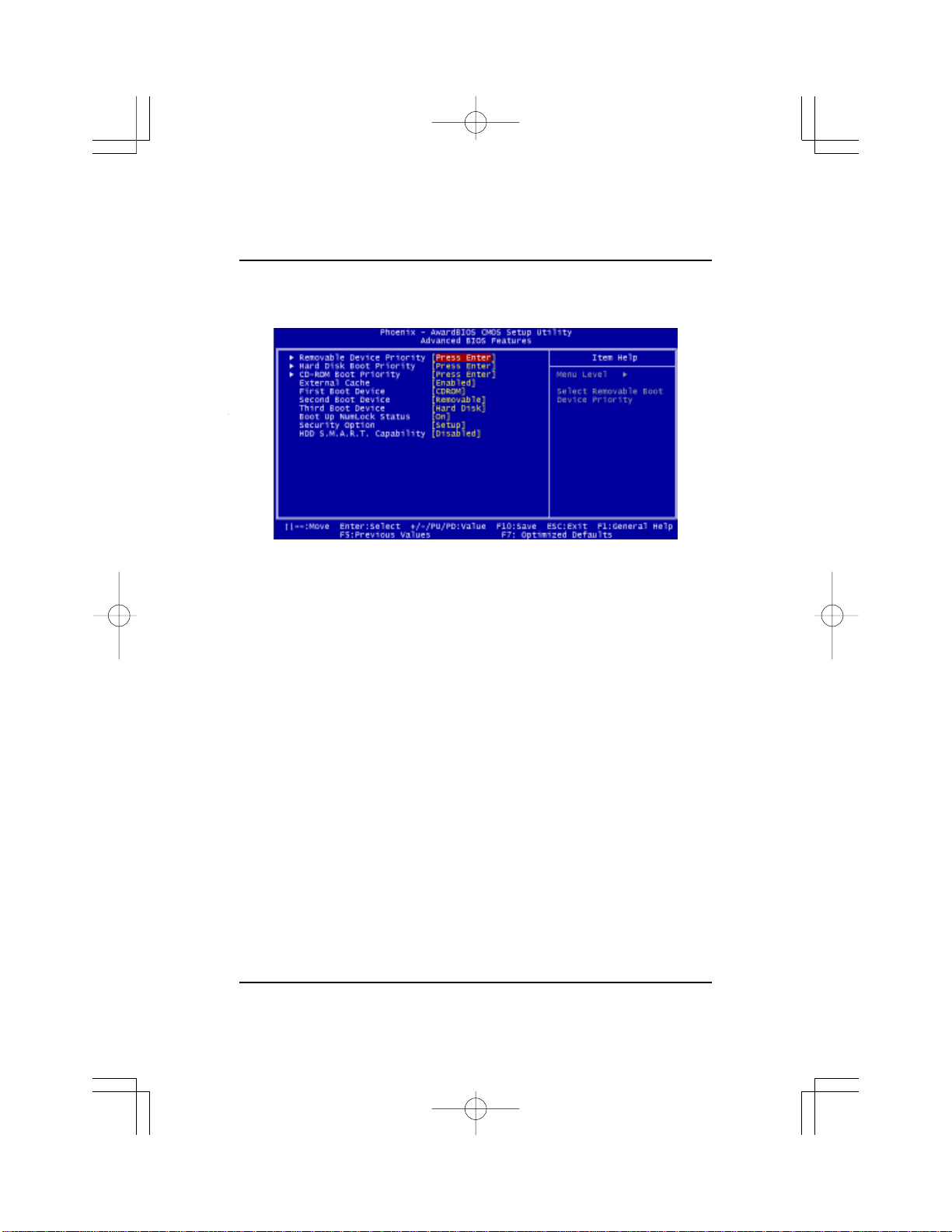
Advanced BIOS Features
Removable Device Priority
This feature allows you to Remova ble Device Priority .
The options are: Flooy Disks, LS120, ZIP 100, USB-F DD0, USB-FDD1, USBZIP0, USB-ZIP1
Hard Disk Boot Priority
This feature will auto detect all hard disks of bootable devices on the
system. It also allows you to select hard disk device booting priority.
The options are: Pri.Master, Pri.Slave, Sec.Master, Sec.Slave, USBHDD0,
USBHDD1, USBHDD2, Bootable Add-in Cards.
CD-ROM Boot Priority
This feature allows you to select the CD-ROM Boot priority.
The options are: Pri. Master, Pri. Slave, Sec. Master, Sec.Slave, USBCDROM0, USB-CDROM1
External Ca che
This controls the status of teh external (L2) cache area. The default is
Enabled. The options are: Ena bled, Disabled.
First/Second/Third Boot Device
This feature allows you to select the boot device priority.
The options are: Remova ble, Hard Disk, CD ROM, Lega cy La n, Disable.
28
Page 29

Boot Up Numlock Status
When set to On, allows the BIOS to automatically enable the Num Lock
Function when the system boots up. The options are: On, Off.
Security Option
Allows you to set the security level of the system.
The options: Setup, System.
HDD S.M.A.R.T. Capability
S.M.A.R.T. stands for Self-Monitoring and Analysis Reporting Technology which allows your hard disk drive to report any read/write errors and
issues a warning with LDCM installed. The options: Disabled, Enabled.
29
Page 30

Mainboard User Guide
Advanced Chipset Features
FSB Frequency
This feature allows you to set the FSB frequency
The options are: 133MHz, 166MHz, 200MHz.
Memory Frequency
This feature allows you to set the memory frequency
The options are: 66%, 100%, 133%, 166%, 200%, Auto
AGP Aperture Size
It allows you to select the main memory frame size for AGP use.
The options list presents all provided possibilities.
AGP 8X Support
Enables AGP 8X supports.
The options are: Disabled, Enabled
AGP Fast Write Capability
Enables Fast W rite protocol for AGP cards.
The options are: Disabled, Enabled
30
Page 31

Integrated Peripherals
IDE Function Setup
On Chip IDE Cha nnel0/1
When enabled, this allows you to use the onboard pri mary/secondary PCI
IDE. The options are: Enabled, Disabled.
IDE Prefetch Mode
When set at Enabled, it allows data to be posted to and prefetched from the
primary IDE data ports. Data prefetching is initiated when a data port read
occurs. The rea d prefetch eliments latency to the IDE data ports a nd allows
them to be performed back to back for the highest possible PIO data transfer rates. The first data port read of a sector is called the demand read.
Subsequent data port reads from the sector are called prefetch reads.
The demand rea d and all prefetch reads must be of the sa me size (16 or 32
bits). The options are: Enabled, Disabled.
IDE DMA trans fer access
This item allows you to disable the IDE DMA(Direct Memory Access)
tra nsfer access function. The options are: Enabled, Disabled.
31
Page 32

Mainboard User Guide
OnChip USB
Enables the USB controllers
The options are: V1.1+V2.0, V1.1
AC97 Audio
This feature auto detects if you use a card with a CODEC to enable or
disable the AC97 audio function. The options are: Auto, Disabled.
MAC Lan(nVIDIA)
Enables the onboard LAN f eature.
The options are: Audio, Disabled
Machine MAC(NV) Address
This feature allows you to select Machine MAC(NV) Addre ss.
The options are: Disabled, Enabled.
Onboard Serial Port 1
If the serial port 1 uses the onboard I/O controller, you can modify your
serial port parameters.
The options are: 3F8/IRQ4, 3E8/IRQ4, 2F8/IRQ3, 2E8/IRQ3, Disa bled.
Onboard Parallel Port
Allows you to select from a given set of parameters if the parallel port uses
the onboard I/O controller.
The options are: Disa bled, 378/IRQ7, 278/IRQ5, 3BC/IRQ7.
Parallel Port Mode
Allows you to connect with an advanced printer vi a the port mode it supports. The options are: SPP, ECP, EPP, EPP+ECP.
ECP Mode Use DMA
This feature allows you to select Direct Memory Access (DMA) channel.
The options are: 1, 3.
32
Page 33

Power Management Setup
ACPI Suspend T ype
This item allows you to select suspend mode when the system is in ACPI
mode. The options are: S1 (POS), S3 (PTR), S1&S3.
Power Man agement
This item allows you to a djust the power management features.
Select User Define for configuring your own power ma nagement f eatures.
Min Saving initiates all predefined timers in their minimum values. Max
Saving, on the other hand, initiates maximum values.
The options are: User Define, M in Saving, Max Saving.
HDD Power Down
This option lets the BIOS turn the HDD motor off when the systemis in
Suspend mode. Selecting 1 Min,..,15 Min allows you to define the HDD
idle time before the HDD enters the Power Saving Mode.
The options 1 Min,..,15 Min will not work concurrently. When HDD is in
the Power Saving Mode, a ny access to the HDD will wake the HDD up.
The options are: Disa bled, 1 Min,..,15 Min.
33
Page 34

Mainboard User Guide
WOL(PME#) From Soft-Off
An input signal form PME on the PCI card awakens the system from a soft
off state. Options: Disabled, Enabled.
WOL(RI#) From Soft-Off
An input signal form RI on the PCI card awakens the system from a soft off
state. Options: Disabled, Enabled.
Power-On by Alarm
When enabled, you can set the date and time in the following two fields.
Any event occurring at the specified date or time awakens the system from
power savings mode. Options: Disabled, Enabled.
PWRON After PWR-Fail
When the system is shut down owing to the power failure, the system will
not be back to power on by itself. This feature allows you to set the
system back to which power status of the system when the system power
is resumed. The options are: Off, On, Former-Sts.
PC Health Status
Vcore / 3.3V / 5V / 12V / -12V / CPU Temperature / SYSTEM Temperature / CPU FA N Speed / SYS F AN Speed
These items allow end users and technicians to monitor data provided by
the BIOS on this mainboard. It is not user-configurable.
34
Page 35

Load Optimized Defaults
This submenu is selected for default settings which provide the best system
performance.
Supervisor/User Password
To enable the Supervisor/User passwords, select the item from the Standard
CMOS Setup. You will be prompted to create your own password. Type your
password up to eight chara cters and press Enter. You will be asked to confirm
the password. Type the password again and press Enter. To disable the
password, press Enter twice when you are prompted to enter a password. A
message appears, confirming the password is disabled.
Under the BIOS Feature Setup, if Setup is selected under the Security Option
field a nd the Supervisor/User Pa ssword is enabled, you will be prompted for a
password every time you try to enter the CMOS Setup Utility. If System is
selected and the Supervisor/User Password is ena bled, you will be requested
to enter the Password every time you reboot the system or enter the CMOS
Setup utility.
Save and Exit Setup
After you have made changes under Setup, press Esc to return to the main
menu. Move the cursor to Save a nd Exit Setup or press F10 and then press Y to
change the CMOS Setup. If you did not change anything, press Esc again or
move the cursor to Exit W ithout Saving a nd pre ss Y to retain the Setup settings.
The following message will appear at the center of the screen to allow you to
save data to CMOS a nd exit the setup utility: SA VE to CMOS a nd EXIT (Y/N)?
Exit without Saving
If you select this feature, the following message will appear at the center of the
screen to allow you to exit the setup utility without saving CMOS modifications:
Quit Without Saving (Y/N)?
35
 Loading...