

Page 1
FIC PRODUCT
□
COMPONENT
First International Computer, Inc.
NEW APPROVAL SHEET
D ATE 2003.11.21
PART NO 25-11141 -00
DESCRIPTION MANU M/B AM39-LS ENG USER' VA0
□
MANUAL
▓
□
P.C.B
□
□
□
POWER SUPPLY
□
MECHANICAL
PURCHASE
SOFTWARE
FILE NO .
25-11141-00
MODEL AM39-LS
REV.
VENDOR
力 捷
REMARK
oApproved by NHRD ▓Approved by FIC-SZ
LINKO
FIC-SZ
NEI-HU
WORLD WIDE
MANAGER
楊博丞 2003.11.21
□
DCC □ QA □ PMC □ CSD
▓
DCH
□
QA2
□
RDCC □ VENDOR □ FAE □ CE
□
FIC-TX □ FIC-BZ □ FIC-CZ ▓ FIC-G Z
LEADER
張新政 2003. 11.21
□
R&D
□
IE
CHECK
謝群根 2003. 11.21
▓
VENDOR
INITIAL
謝群根 2003. 11.21
▓
QA1
RELEASE FROM:FIC R&D
Form update:2002/11/1 QP-R705-F02
Page 2
FIRST
COMPONENT
INTERNATIONAL
COMPUTER
PART NUMBER
DESCRIPTION
WHERE USED
BRAND
MODEL(S)
CONTACT
COMPONENT OK NG
FUNCTIONAL TEST
RELABLITY TEST
COMPATIBILY TEST
H/W OK NG
ELECTRICAL SPEC
ENVIONMENTAL
COMPATIBILITY FEATURE
25-11141-00
MANU M/B AM39-LS ENG USER' VA0
AM39-LS
周 宇 清
COMMENTS:
COMMENTS:
APPLICANT
VENDOR
MARK P/N
PHONE
APPROVAL
SHEET
力 捷
(0769) 7313082
CE BY:
CE CHECK:
H/W BY:
謝 群 根
謝 群 根
M/E OK NG
DIMENSION CHECK
MATERIAL CHECK
COATING CHECK
IE CHECK
EMI & SAFETY OK NG
SAF-ETY FEATURE
EMI FEATURE
MATERIAL CHECK
LABELING CHECK
ATTACHMENTS
REMARK:
Failure Rateλ(Failure/106 hours)= Vendor MIL-HDBK-217F
;
;
COMMENTS:
M/E BY:
;SAMPLE DRAWING ;SPEC PHOTO ECN
謝 群 根
SAFETY BY:
EMI BY:
謝 群 根
APPROVAL
TEMPORARY
REJECT
;
1'ST SOURCE 2'ND SOURCE
Page 3
承 認 書
客 戶
品 名
料 號
工程部
才 眾
說 明 書
25-11141-00
客戶確認簽章
本公司確認簽章
品管部
品管部經理
曹菊蘭
送樣日期:
陳文華
______
2003
年
11
_____
月
胡培基
_____
19
日
東莞力捷紙品有限公司
地 址: 東莞市清溪鎮重河管理區河柏橋村
電 話: 0769-7313082088
傳 真: 0769-7313080
E-mail: [email protected]
Page 4
東莞力捷紙品有限公司
產 品 基 本 資 料
確
認
意
見
附樣:
生 產 技 術 資 料 表
產 品
編 號
顏 色
尺 寸
規 格
核 准 胡 培 基 審 核 曹 菊 蘭 填 表 李 先 芳
25-11141-00 品 名 說明書 材 質
BK+877C
表 面
處 理
148*210mm 成型方式 裁切, 折頁, 膠裝
OPP 膜(正面)
條碼值:
實測值:
封頁: 200P 銅西卡
內頁: 70P 蘭白模造
無
Page 5

K7M-400A
MAINBOARD
MANUAL
DOC No.: M03603
Rev. : A0
Date : 11, 2003
Part No. : 25-11141-00
Page 6

Notice
Handling Precautions
Warning:
1. Static electricity may cause damage to the integrated circuits on
the motherboard. Before handling any motherboard outside of its
protective packaging, ensure that there is no static electric
||||||charge in your body.
2. There is a danger of explosion if the battery is incorrectly
replaced. Replace only with the same or an equivalent type
||||||recommended by the manufacturer.
3. Discard used batteries according to the manufacturer’s
instructions.
4. Never run the processor without the heatsink properly and firmly
attached. PERMANENT DAMAGE WILL RESULT!
Observe the following basic precautions when handling the motherboard
or other computer components:
Wear a static wrist strap which fits around your wrist and is
|||||||||connected to a natural earth ground.
Touch a grounded or anti-static surface or a metal fixture such as a
water pipe.
Avoid contacting the components on add-on cards, motherboards,
and modules with the golden fingers connectors plugged into the
expansion slot. It is best to handle system components by their
mounting brackets.
The above methods prevent static build-up and cause it to be discharged
properly.
Tr ademark
All trademarks mentioned in this manual are registered properly of
the respective owners.
Handling Precautions
This ma nual may not, in whole or in part, be photocopied, re produced,
transcribed, translated, or transmitted in whatever form without the
written consent of the manufacturer, except for copies retained by the
purchaser for personal archival purposes.
Page 7

Table of Contents
Table of Contents
Chapter 1 Overview
Package Checklist .......................................................................... 1-2
The K7M-400A Mainboard ....................................................... 1-3
Main Features................................................................................ 1-4
FIC Unique Innovation for Users (NOVUS) -
Enhanced Mainboard Features and System Support ..................... 1-6
Chapter 2 Installation Procedures
1). Set System Jumpers .................................................................. 2-2
Clear CMOS ...................................................................... 2-2
BIOS Protect...................................................................... 2-2
Front Side Bus Frequency................................................. 2-3
2). Install Memory Modules .......................................................... 2-4
3). Install the CPU .......................................................................... 2-5
Connect A TX Power.......................................................... 2-6
4). Install Expa nsion Cards............................................................. 2-7
5). Connect Devices ....................................................................... 2-8
Floppy Diskette Drive Connector ...................................... 2-8
IDE Device Connectors ..................................................... 2-9
Power Connectors ............................................................. 2-9
Front Pa nel Block, Power LED, IR and Speaker Connector 2-10
1394 Connectors (optional) ............................................... 2-12
CD Audio-In Connector .................................................... 2-12
SPDIF Out Connector ....................................................... 2-13
Serial IRQ Connector......................................................... 2-13
Chassis Intrusion Connector ............................................ 2-14
Fan Connectors ................................................................. 2-14
Serial AT A Connectors ...................................................... 2-15
PS/2 Keyboard and Mouse Connector.............................. 2-16
Printer Connector .............................................................. 2-16
Universal Serial Bus Connectors....................................... 2-17
RJ45 LAN Connector ........................................................ 2-17
Serial Port Connector ........................................................ 2-18
Audio I/O Jacks ................................................................ 2-18
Front Audio Connector ..................................................... 2-19
CRT Connector.................................................................. 2-19
i
Page 8
K7M-400A Mainboard Ma nual
Chapter 3 BIOS Setup
CMOS Setup Utility ....................................................................... 3-1
Sta ndard CMOS Setup................................................................... 3-2
Advanced BIOS Features .............................................................. 3-4
Advanced Chipset Features .......................................................... 3-7
Integrated Peripherals.................................................................... 3-11
Power Management Setup ............................................................. 3-15
PnP/PCI Configurations................................................................. 3-18
PC Health Status ............................................................................ 3-20
Load Opti mized Defaults ................................................................ 3-20
Supervisor/User Password ............................................................ 3-20
Save a nd Exit Setup........................................................................ 3-21
Exit without Saving ........................................................................ 3-21
ii
Page 9

Chapter 1
Overview
Overview
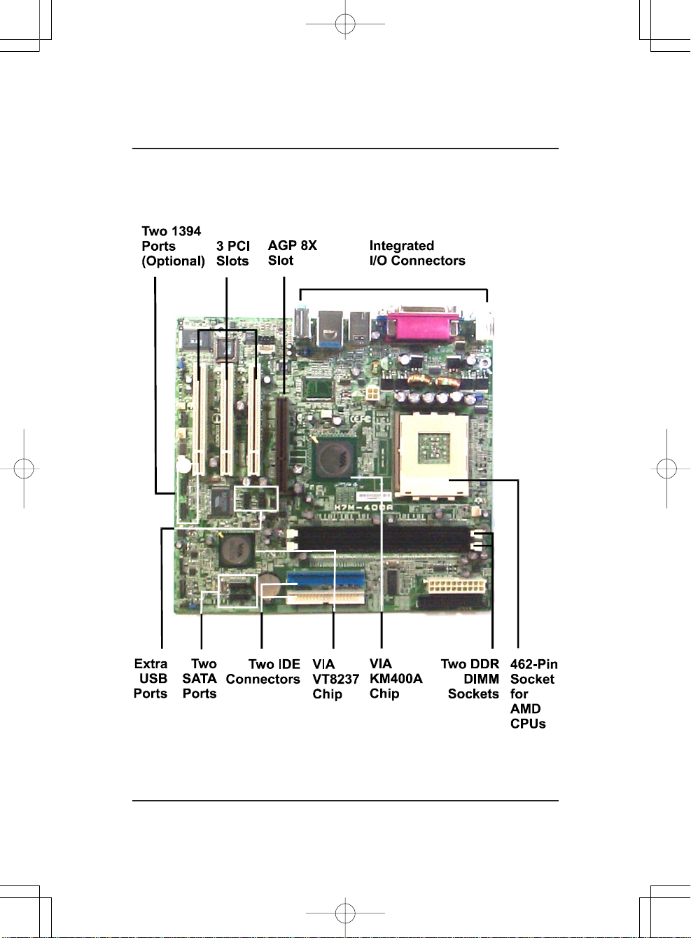
The new microATX 462-pin board supports a full range of the latest generation
AMD® Athlon XP processors. The leading edge VIA® chipset was designed to work in the 462-pin package running at the FSB 200/266/333/400
MHz. Built using leading edge technology, the AMD® Athlon XP processors provide a significa nt improvement in performance over previous processors. T wo DDR 200/266/333/400 SD RAM sockets allow for up to 2 GB memory
capacity. Support for Ultra DMA/133 protocol and its high-speed interface
further ensures that data transfer speeds are improved, especially for the long
sequential transfers required by audio/visual applications.
The board features onboard audio and LAN function; also, the serial ATA
feature replaces the standard parallel ATA physical storage interface and allows future enhancements to the computing platform. It is completely software compatible with parallel ATA, requiring no modification to your operating system. For more details, please read the help file in the lst Utilities CD.
The board comes with a versatile ra nge of I/O features such a s seri al port COM
port, 1 CRT port, 1 parallel port, 1 LAN, 2 optional IEEE 1394, 1 PS/2 mouse a nd
keyboard connector, 8 USB ports, 1 media connector (front audio, Line-in,
Line-out and Mic-in). In addition, the board is equipped with 2 dual channel
enha nced PCI bus master IDE connectors. Ample expa nsion is availa ble through
3 PCI and 1AGP to allow enjoyment of the AMD CPU’s benefits in internet
applicatons, video/3D graphics performance, and so forth.
Other key features are Remote On/Off, Auto Power Failure Recovery, integrated temperature monitoring and system fan control. Also included are a lst
Utilities CD with enhanced drivers and a few bundled software solutions.
1 - 1
Page 10
K7M-400A Mainboard Ma nual
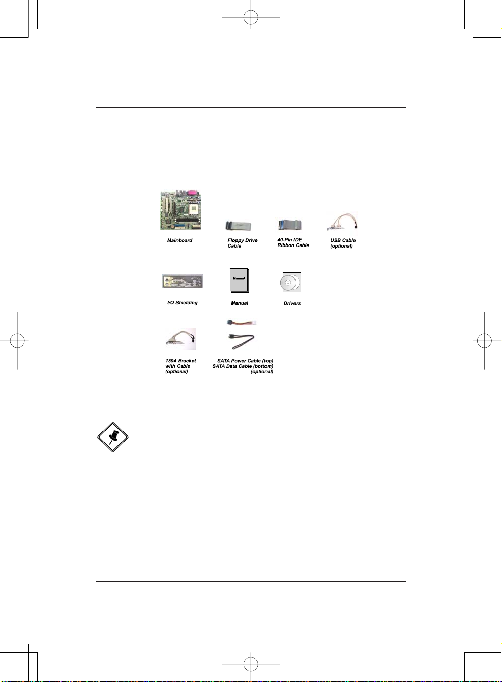
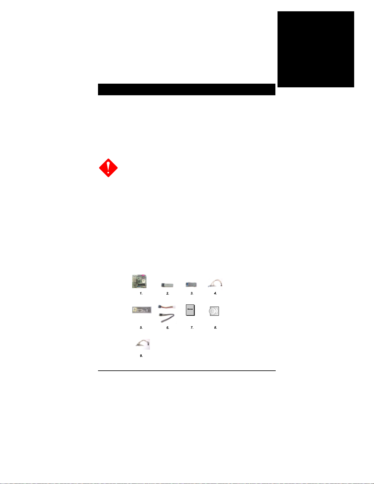
Package Checklist
If you discover any item below was damaged or lost, please contact your
vendor.
1 - 2
NOTE: A 1st Utilities CD, which contains patch files, onboard video/
audio chip drivers, related online help and other useful information,
can be found in your mainboard package.
Please install it immediately after your Windows operating system
installation is complete. Place your 1st Utilities CD in the drive and
an operating menu will appear on your monitor. Please select Auto
Installation. It will automatically detect which software tools (patch
files, drivers) the mainboard needs. Press OK to go through the
whole installation procedure in a very straight forward and easy
way. It will also provide you with a custom installation feature to
select the patch files and software drivers you want for the onboard
chip’s use. The top menu of the 1st Utilities CD lists all the func-
tions that are allowed by this board.
Page 11
The K7M-400A Mainboard
Overview
1 - 3
Page 12
K7M-400A Mainboard Ma nual
Main Features
CPU
Duron: 1.0 - 1.3 GHz at FSB 200 MHz
1.6 - 1.8 GHz at FSB 266 MHz
Athlon : 1.0 - 1.4 GHz at FSB 200/266 MHz
Athlon XP:
Palomino Core: 1500+ - 2100+ at FSB 266 MHz
Thoroughbred Core: 1700+ - 2600+ at FSB 266/333 MHz
Barton Core: 2500+ - 3200+ at FSB 333/400 MHz
Chipset
North Bridge: VIA® KM400A
South Bridge: VIA® VT8237
Memory
2 Memory Sockets:
Support 184-pin DD R 200/266/333/400 MHz
total Memory Size up to 2 GBs
Expansion Slots
AGP Slot: Support 2.0 4X/8X (0.8 - 1.5V)
3 PCI Slots
IDE Connections
2 IDE Connectors - PIO Mode, Ultra DM A 66/100/133
Up to 4 Devices
SAT A Connections
2 Ports Controlled by embedded VIA VT8237® SATA Function
1 - 4
Page 13

Audio Features
AC97 2.2 complia nt
LINE_IN, LINE_OUT, MICROPHONE_IN Jack
Front Audio Pinheaders
I/O Ports
2 IDE Connectors PIO, Bus Master , Ultra DMA 66/100/133
up to 4 Devices
- 1 Serial Port COM1 / 1 CR T Port
2 Serial ATA Connectors
1 Floppy Connector
1 Parallel Port
PS/2 Mouse and PS/2 Keyboard
8 USB 1.1/2.0 Ports
LAN
VT6103L 10/100M Fast Ethernet
RTL8110S Giga-bit Ethernet (optional)
Mounting Holes
6 Holes
Overview
Mainboard Size
9.0 x 9.6 (unit: inch)
IEEE 1394 Ports (optional)
VT6307L
2 Ports
1 Bracket with Cable
1 - 5
Page 14
K7M-400A Mainboard Ma nual
FIC Unique Innovation for Users (NOVUS) -
Enhanced Mainboard Features and System Support
BIOS Guardian
BIOS Guardian effectively acts as a fire-wall against viruses that can attack the BIOS while the system is running and when default is enabled.
WAR NING:
BIOS Guardi a n must be disabled bef ore reflashing the BIOS.
NOTE:
Please read Page 3-7 for detail information.
Easy Key
Instead of completing the multi-layered BIOS setup process, the se 3 Ea sy
Key functions provide direct access to the Sub-Menu when completing
BIOS setting adjustments.
Easy-Keys are as follows:
Ctrl + p: To load Performance Default settings and restart.
Ctrl + f: To load Fail-Saf e Default settings and restart.
1 - 6
Page 15
Installation Procedures
Chapter 2
Installation Procedures
The mainboard has several user-adjustable jumpers on the board that allow you to
configure your system to suit your requirements. This chapter contains information
on the various jumper settings on your mainboard.
To set up your computer, you must complete the following steps:
Step 1 - Set system jumpers
Step 2 - Install memory modules
Step 3 - Install the Central Processing Unit (CPU)
Step 4 - Install expansion cards
Step 5 - Connect ribbon cables, cabinet wires, and power supply
Step 6 - Set up BIOS software
Step 7 - Install supporting software tools
WARNING: Excessive torque may damage the mainboard. When
using an electric screwdriver on the mainboard, make sure that
the torque is set to the allowable range of 5.0 ~ 8.0kg/cm.
Mainboard components contain very delicate Integrated Circuit
(IC) chips. To prevent static electricity from harming any of the
sensitive components, you should follow the following precautions whenever working on the computer:
1. Unplug the computer when working on the inside.
2. Hold components by the edges and try not to touch the IC
||||chips, leads, or circuitry.
3. Wear an anti-static wrist strap which fits around the wrist.
4. Place components on a grounded anti-static pad or on the bag
that came with the component whenever the components are
separated from the system.
2 - 1
Page 16
K7M-400A Mainboard Ma nual
1). Set System Jumpers
Clear CMOS
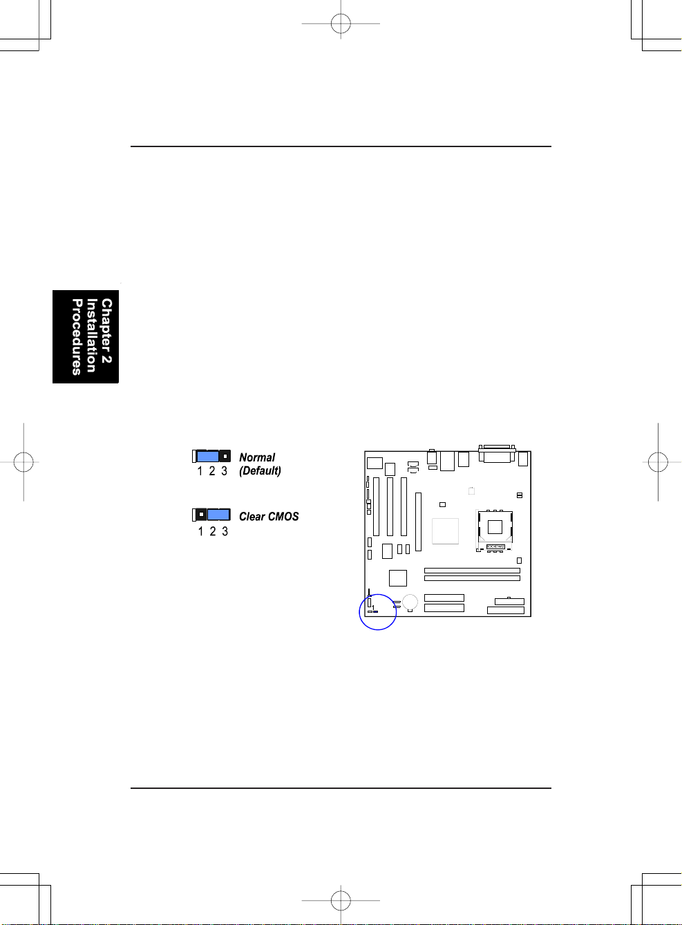
The CMOS RAM is powered by the onboard button cell battery.
T o clear the RTC data:
(1) Turn off your computer;
(2) Open the system case and disconnect the ATX power cable;
(3) Place the jumper cap onto the pinpair 2-3 for at least 6 seconds
to clear CMOS data;
(4) Place the jumper cap onto the pinpair 1-2 to normal operation;
(5) Close the system case and connect the ATX power cable;
(6) Turn on your computer until CMOS checksum error appears;
(7) Press the Delete key as it boots;
(8) Enter the BIOS Setup to re-enter user preferences.
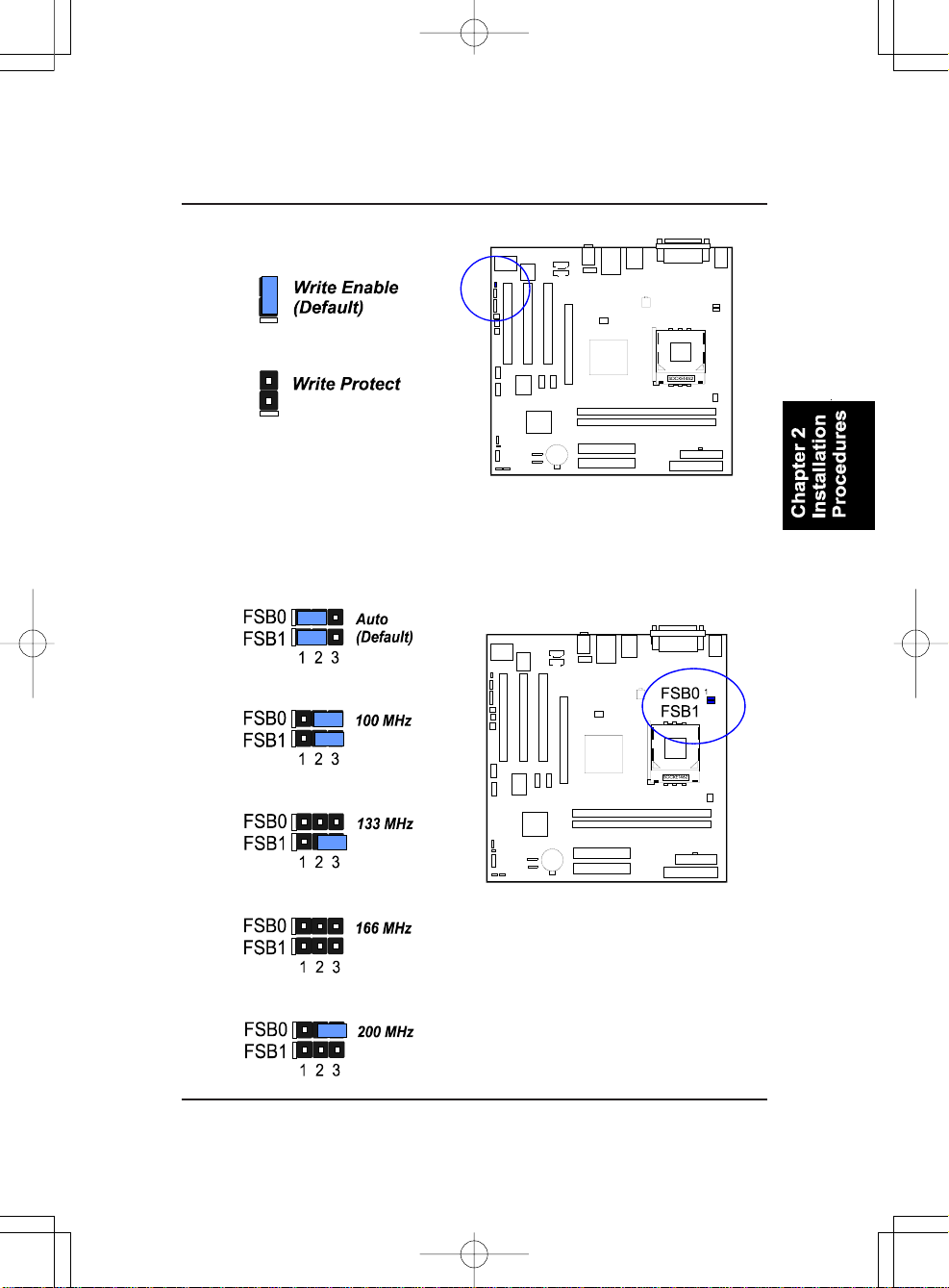
BIOS Protect
The jumper helps to prevent the BIOS ROM from being overwritten by
mistake.
2 - 2
Page 17
Installation Procedures
Front Side Bus Frequency
The jumpers together decide the setting of FSB frequency of the mainboard.
2 - 3
Page 18
K7M-400A Mainboard Ma nual
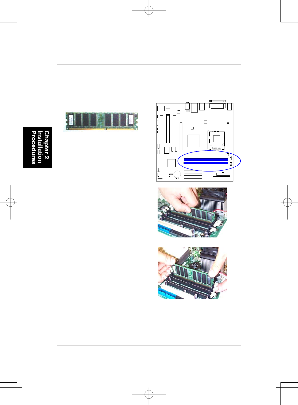
2). Install Memory Modules
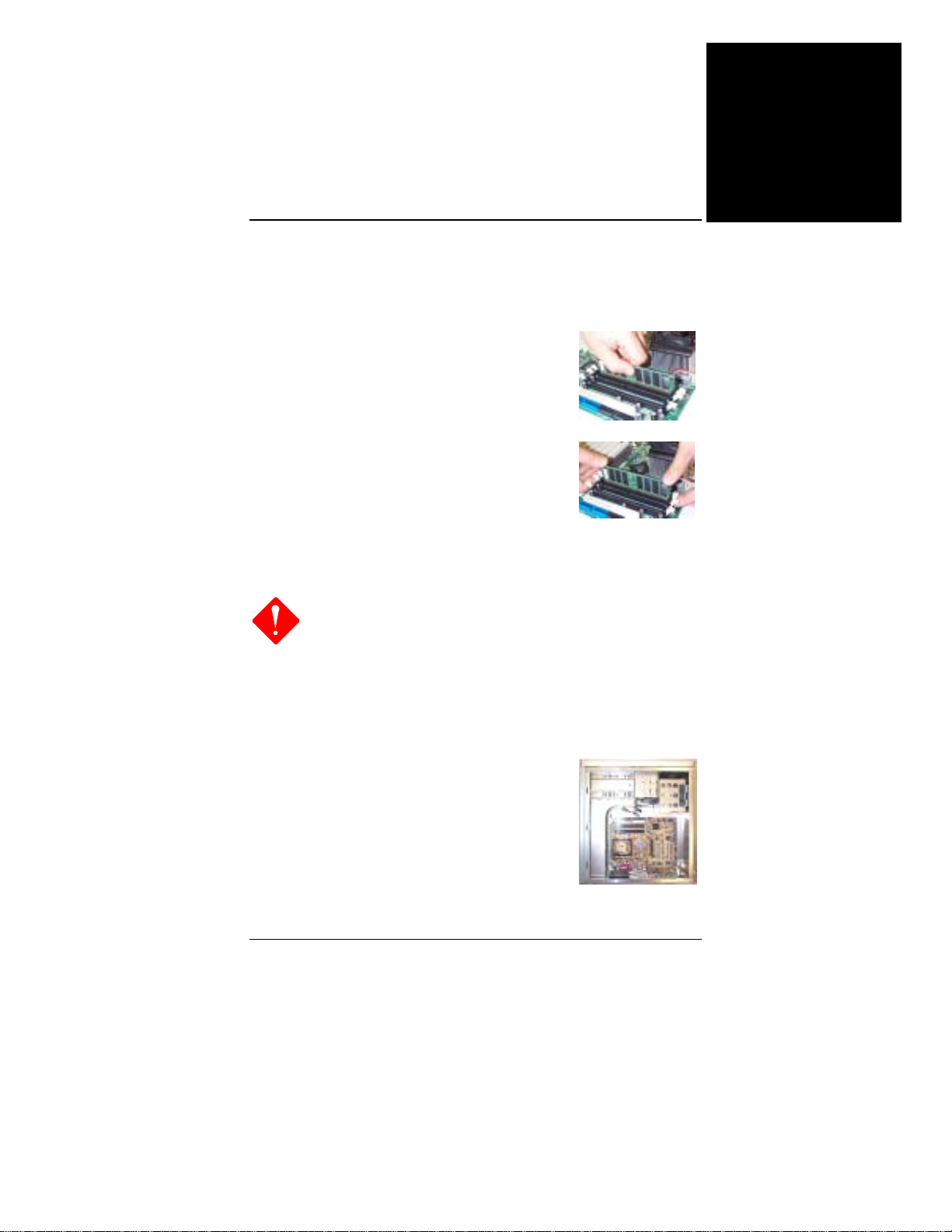
1. Locate DDR DIMM sockets
on the mainboard.
2. Install DDR DIMM straight
down into the socket 1 using both
hands, then socket 2, and so forth.
3. The clip on both ends of the
socket will close up to hold the
DDR DIMM in pla ce when the DD R
DIMM reaches the socket bottom.
Press the clips outward with both hands to remove the DIMM.
2 - 4
Page 19
Installation Procedures
3). Install the CPU
The mainboard has a built-in Switching Voltage Regulator to support CPU
Vcore autodetection. That is, it has the a bility to detect and recognize the CPU
voltage, clock, ratio. Users can view the report about CPU frequency through
Frequency / Voltage Control on the BIOS Setup Screen.
CAUTION:
1. The heat sink and fan you installed must be approved by AMD.
2. The mainboard must be placed on a solid surface to avoid shak
ing while install the heat sink and fan are installed on the board.
3. The heat sink must make tight contact with the CPU top.
4. Never run the processor without the heat sink properly and firmly
attached. PERMANENT DAMAGE WILL RESULT!
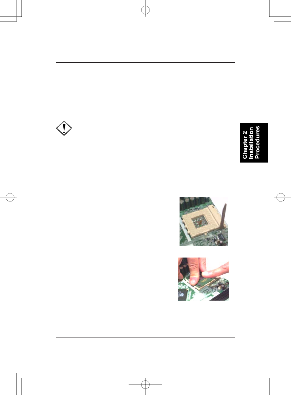
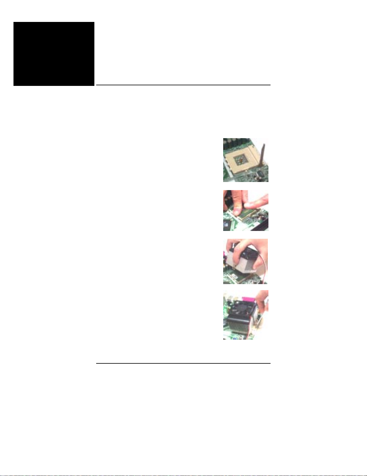
The procedures below shows you how to install your CPU and its fan
a nd heatsink. First of all, locate the CPU socket on the mainboard.
1. Swing the lever upward to 90 degree.
2. Install the CPU, making sure of the pin 1
orientation by aligning the socket corner marking
with the socket corner closest to the lever tip.
Do not insert the CPU by force. Make sure the
processor is fully inserted into the socket on all
sides.
Apply some thermal materials, such as paste or
tape, on the CPU top; and install a fan with a
heatsink is approved by the manufacturer to
avoid CPU damage. For detail information,
please refer to the CPU manufacturer website.
Affix the CPU by pressing the lever downward
and locking it beside the socket.
2 - 5
Page 20
K7M-400A Mainboard Ma nual
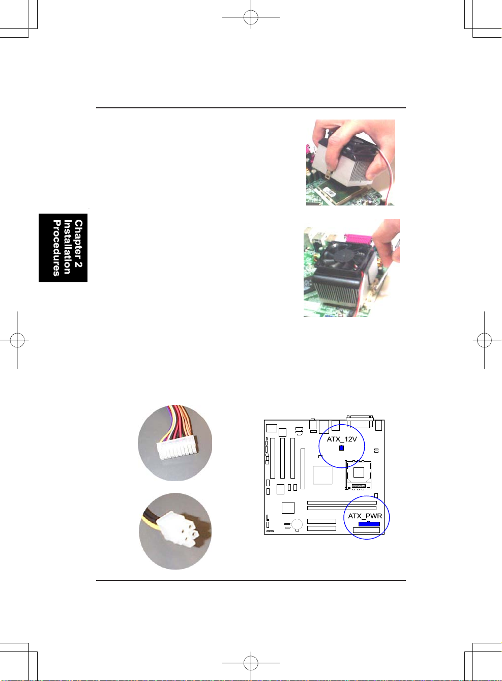
3. Place the fan with heatsink on the CPU top
and press down on the two plastic clips,
hooking them up with the holes on the two
sides of the retention module.
4. Press the white bar on each clip down to
fasten the fan set on the retention module.
Connect ATX Power
The 20-hole power plug (1st figure) is connected to the ATX power 20-pin
pinheaders. The 4-hole 12V power plug (2nd figure) is inserted in the ATX_12V
power connector.
2 - 6
Page 21
Installation Procedures
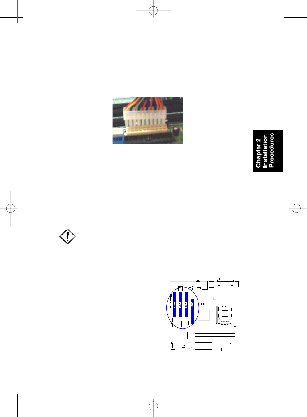
The plug from the power supply can only be inserted in one orientation
because of the different hole sizes. Find the proper orientation and push down
firmly making sure that the pins are aligned.
4). Install Expansion Cards
This section describes how to connect an expansion card to one of your
system expansion slots. Expansion cards are printed circuit boards that, when
connected to the mainboard, increase the capabilities of your system. For
example, expansion cards can provide video and sound capabilities. The
mainboard features one AGP and three PCI bus expansion slots.
CAUTION:
1.Make sure to unplug the power supply when adding or remov
ing expansion cards or other system components. Failure to
do so may cause severe damage to both the mainboard and
expansion cards.
2.Always observe static electricity precautions.
3.Please read Handling Precautions at the start of this manual.
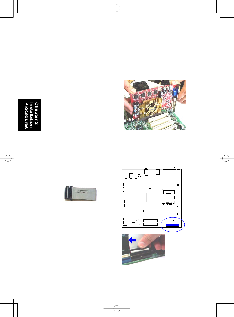
1. Select an availa ble expansion slot.
2 - 7
Page 22
K7M-400A Mainboard Ma nual
2. Remove the corresponding slot cover from the computer chassis. Unscrew the mounting screw that secures the slot cover and pull the slot cover
out from the computer chassis. Keep the slot cover mounting screw nearby.
3. Push the card firmly into the slot.
Push down on one end of the expansion card, then the other. Use this rocking motion until them card is firmly
seated inside the expansion slot. Secure the card with the screw removed
in Step 2.
5). Connect Devices
Floppy Diskette Drive Connector
This connector provides the connection with your floppy disk drive.
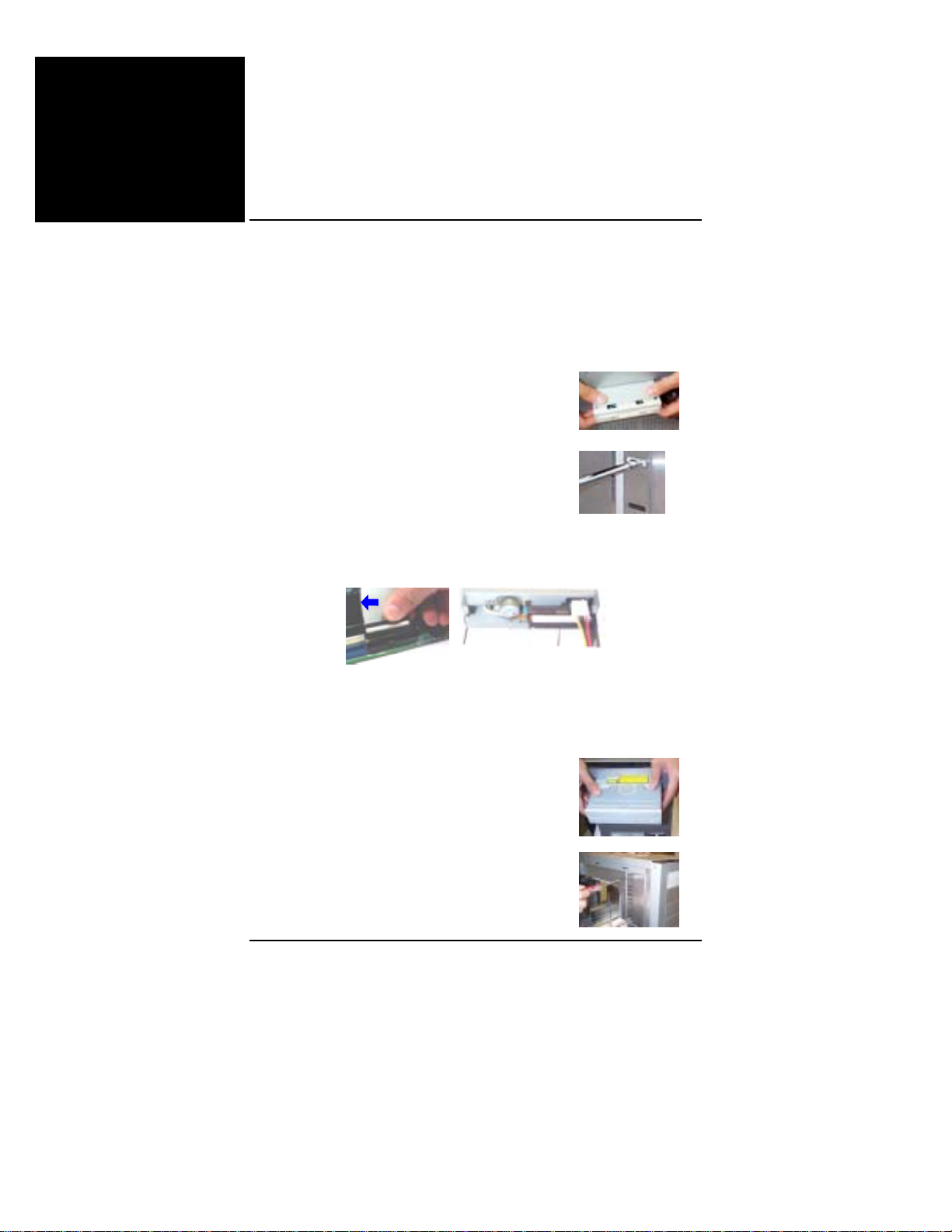
Insert the floppy ribbon cable
(below) onto the floppy connector.
The colored stripe (indicated by the
arrow head, right) of the ribbon cable
must be the same side as Pin 1.
2 - 8
Page 23

Installation Procedures
IDE Device Connectors
The two connectors, IDE1 (PRIMARY)
a nd IDE2 (SECONDARY), are used f or
your IDE hard disk drives, CD drives,
LS-120|drives, or IDE ZIP drives.
Insert the floppy ribbon cable
(below) onto the floppy connector.
The colored stripe (indicated by the
arrow head, right) of the ribbon cable
must be the same side as Pin 1.
Power Connectors
The 20-pin male block connector is connected to the ATX power supply. The
4-pin male block connector is for the ATX_12V power supply. Both connectors are linked with your ATX power supply . The plug from the power supply
ca n only be inserted in one orientation because of the diff erent hole sizes. Find
the proper orientation and push down firmly making sure that the pins are
aligned.
2 - 9
Page 24
K7M-400A Mainboard Ma nual
Front Panel Block, Power LED, IR, and Speaker Connector
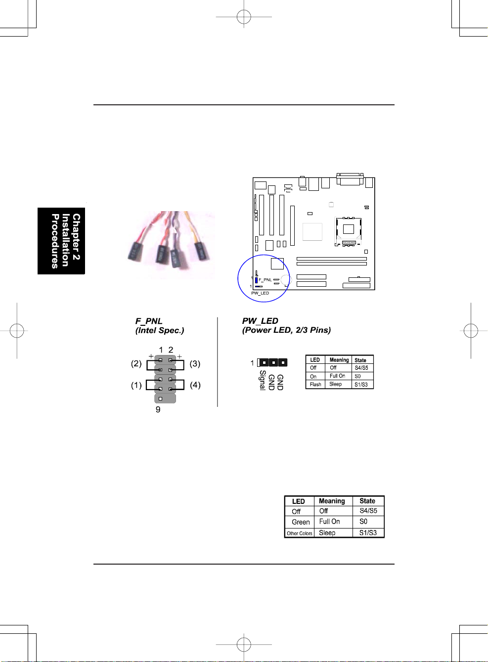
This block connector includes the connectors for linking with Power LED (3pin), HDD LED, power button, power/sleep/message waiting button, and the
reset button on the front panel of the system case. Please identify the polarities of the plug wires for the case speaker and LEDs.
The plug wires (below) polarities
of these buttons will not affect
the function.
(1) Reset Switch is connected to the reset button. Push this switch to reboot
the system instead of turning the power button off and on.
(2) HDD LED is connected to the IDE device indicator. This LED will blink
when the hard disk drives are activated.
(3) Power (Single a nd Dual) /Slee p LED
Please refer to the ta bles below f or the representations of LED states.
There is a nother 3-Pin Power LED connector on
board for some cases that have a 3-pin plug.
2 - 10
Page 25
Installation Procedures
(4) Power Button is connected with the power button. Pushing this switch
allows the system to be turned on and off rather than using the power supply
button.
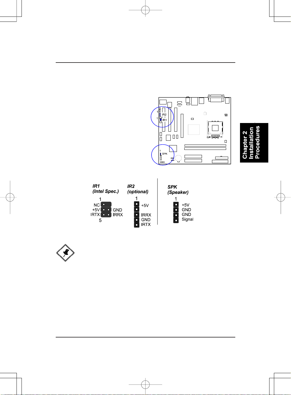
IR1/IR2 is a pinheader that is
used for linking with your ID
device to allow transmission of
data to another system that also
supports the IR feature.
Speaker is connected with the
case speaker.
NOTE: To use IR functions you must adjust the BIOS features introduced in the section of Integrated Peripherals, Chapter 3, for your
IR devices.
2 - 11
Page 26
K7M-400A Mainboard Ma nual
1394 Connectors (optional)
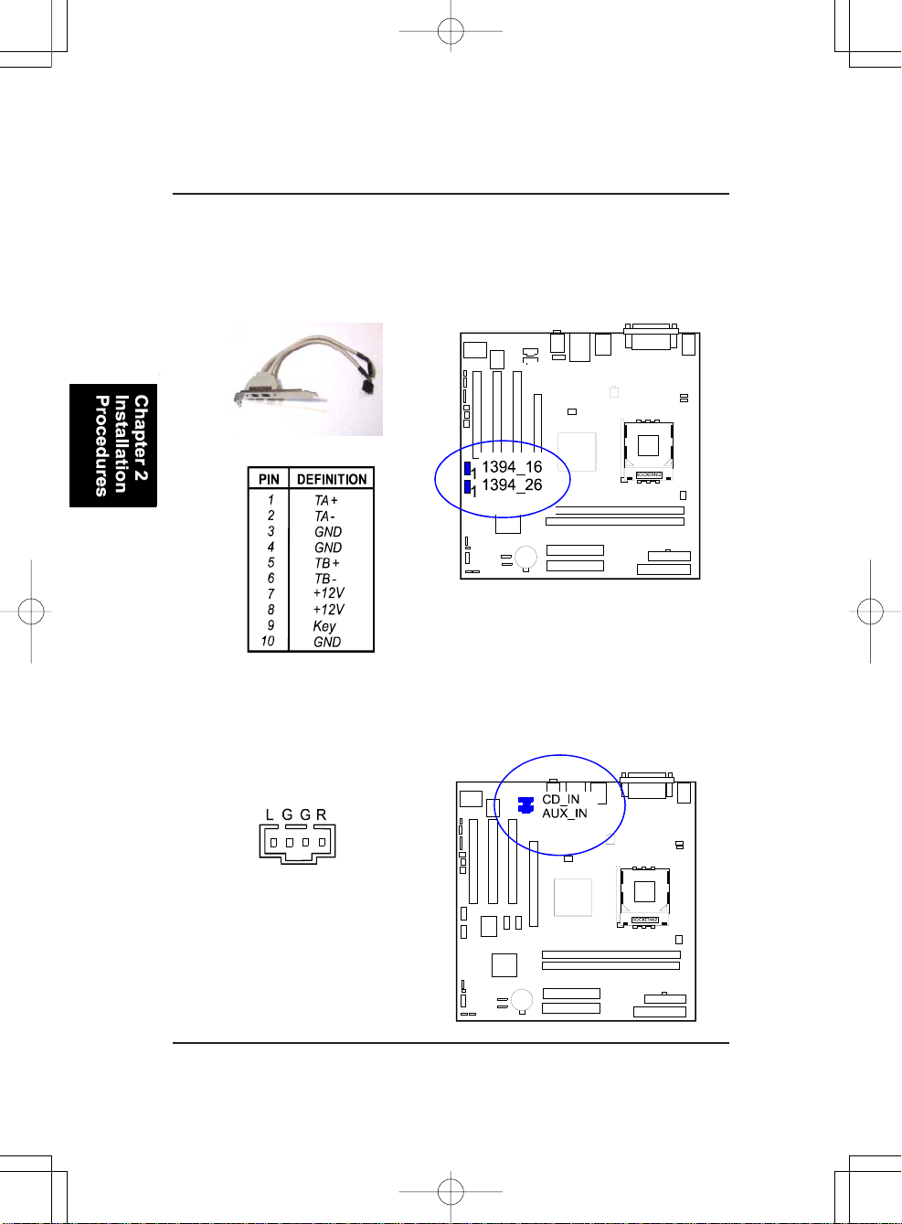
The 2 optional 1394 pinheaders on the board provides you, by an optional
bracket with cable (see the figure below), with two connections f or peri pherals
which have 1394 connectors. The pin definitions of the 1394 pinheaders are
listed below also.
CD Audio-In Connectors
The connectors, CD_IN and AUX_IN, are for CD-ROM drive audio analog
input use. The pin assignment are: Pin 1 is Left, Pin2 and 3 are GND, Pin 4 is
Right.
2 - 12
Page 27
Installation Procedures
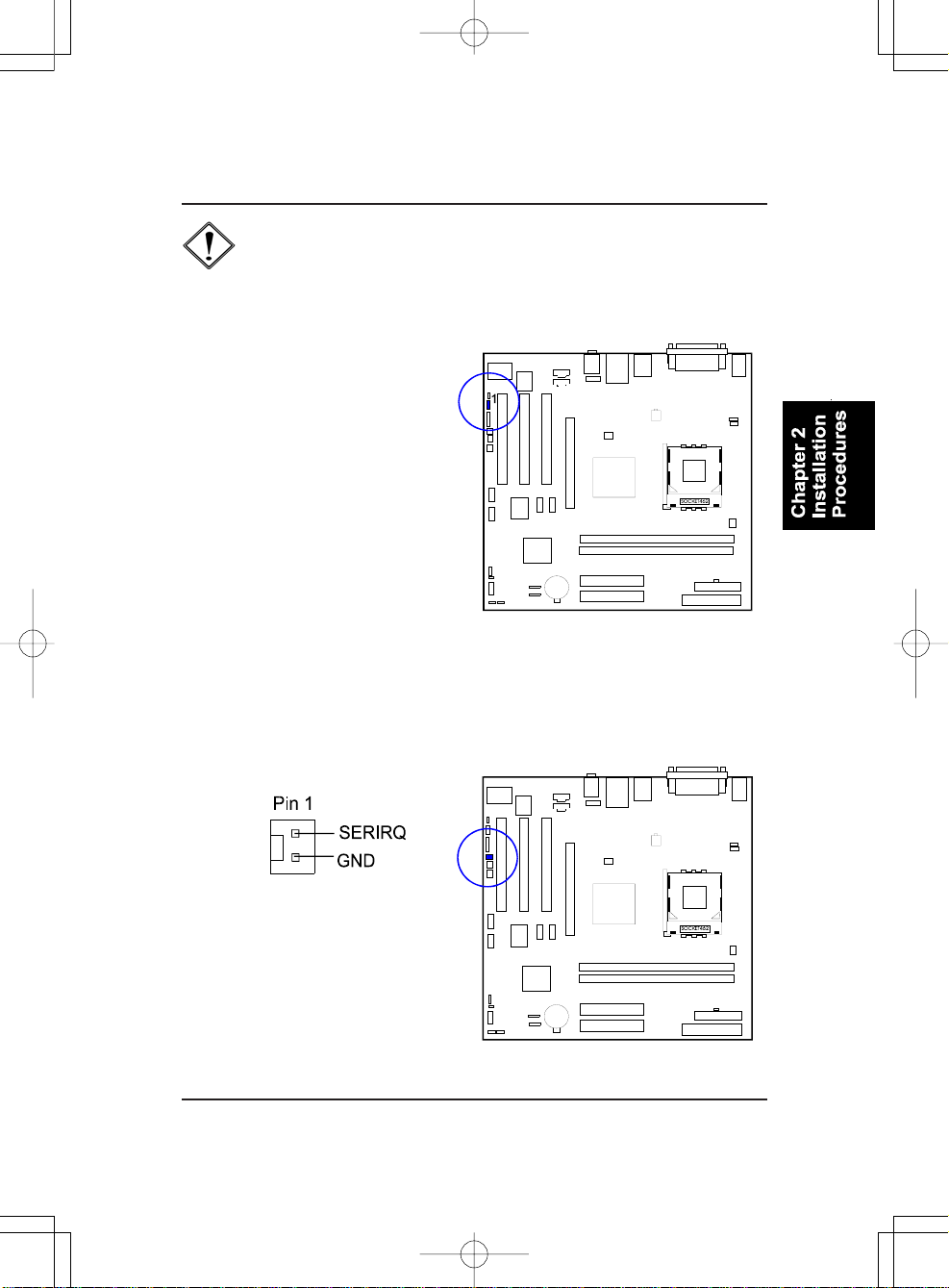
CAUTION: Improper orientation of SPDIF connection may cause
damage of your device.
SPDIF Out Connector
The mainboard equipped one 1x3
pinheader. It is used for SPDIF digital audio output. Pin 1 is +5V, Pin 2
is SPDIF , Pin3 is GND.
Serial IRQ Connector
This 2-pin connector is used for some system integration use.
2 - 13
Page 28
K7M-400A Mainboard Ma nual
Chassis Intrusion Connector
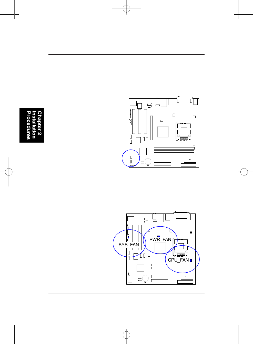
This connector is for a chassis designed with intrusion detection feature. It
needs a chassis intrusion sensoror on the chassis. If a chassis part is moved,
the sensor activates and releases a signal in order to this connector to record
a chassis intrusion event. Pin 1is Signal, Pin 2 is GND.
Fan Connectors
The two connectors, CPU_F A N and SYS_FAN are linked to the CPU fan and
case fan, respectively. PWR_FAN can be used with the power supply cooling
fa n. Pin1 is GND, Pin2 is +12V , Pin3 is Signal.
2 - 14
Page 29
Installation Procedures
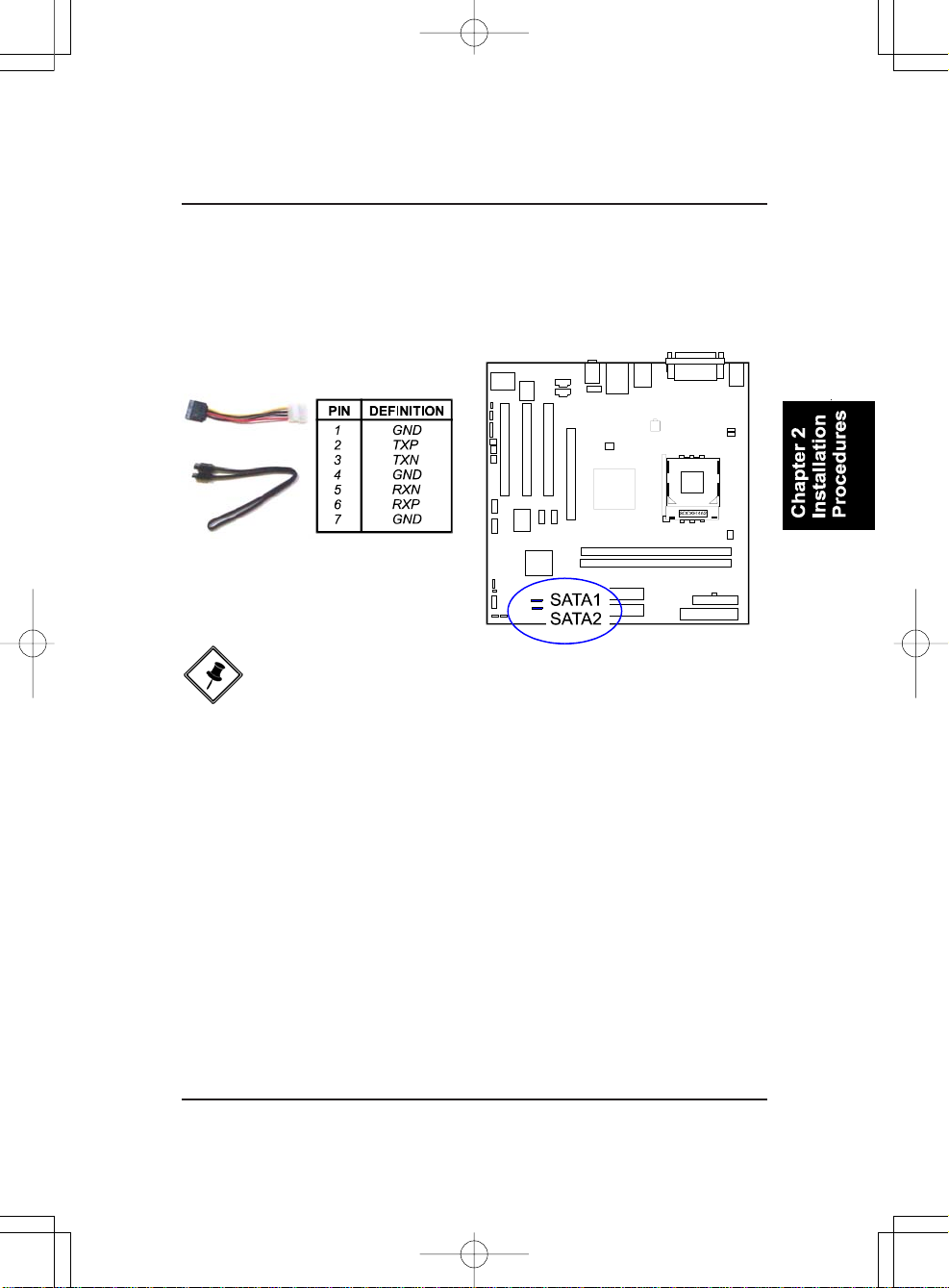
Serial ATA Connectors
The 2 SATA connectors provide you with connections to serial ATA devices
that conform to the Serial ATA specification. Serial ATA supports all ATA and
ATAPI devices. The pictures below left show the two SATA cables (the top
one is for power; the bottom one is for data).
NOTE: To use SATA functions must adjust BIOS features introduced
in the section of Integrated Peripherals, Chapter 3, for your SATA
devices.
2 - 15
Page 30
K7M-400A Mainboard Ma nual
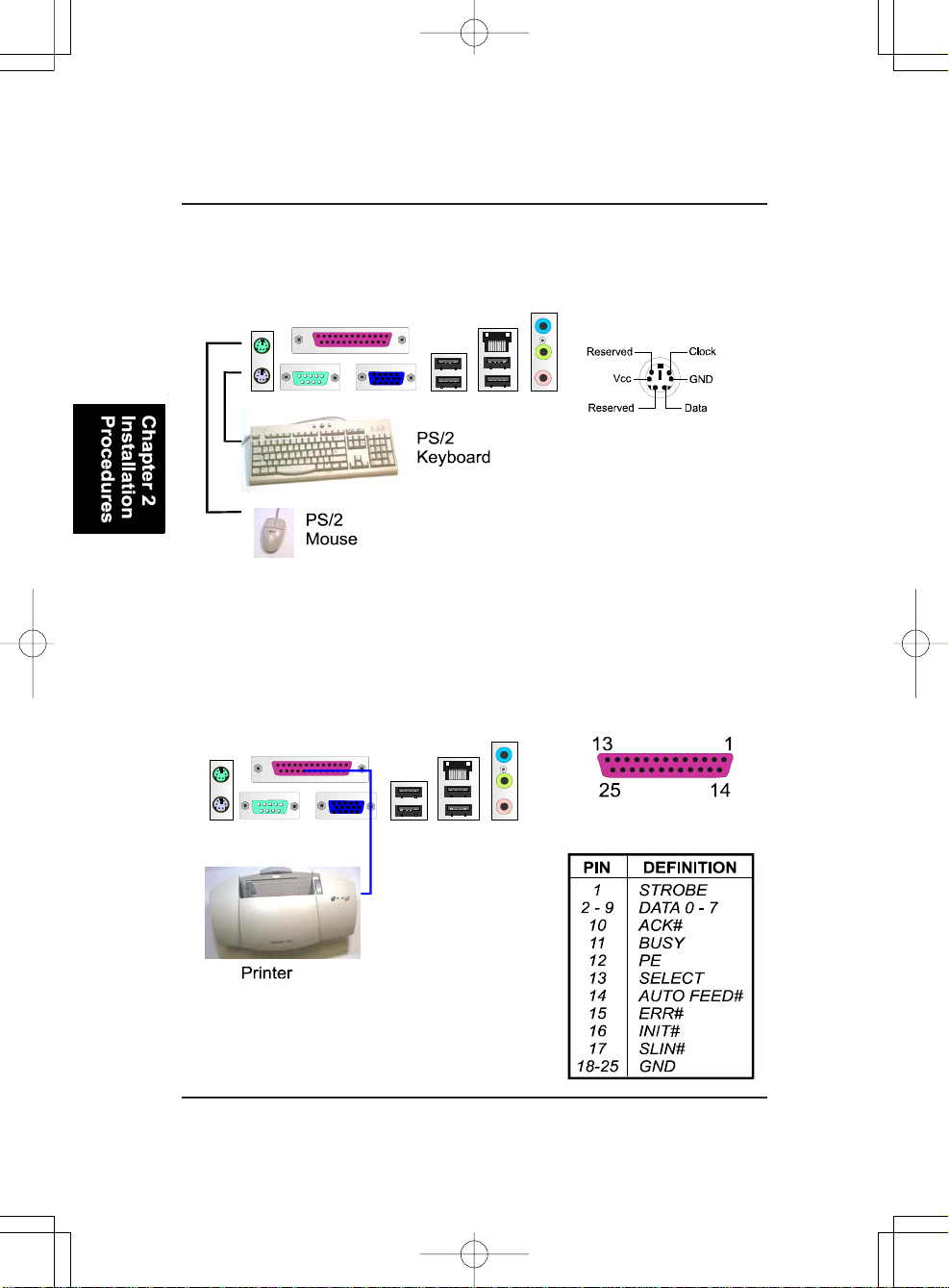
PS/2 Keyboard and Mouse Connector
These two 6-pin female (PS/2 keyboard is purple color a nd PS/2 mouse is green
color) connectors are used for your PS/2 keyboard and PS/2 mouse.
Printer Connector
This 25-pin D-Sub female connector (burgundy-colored) is attached to your
printer.
2 - 16
Page 31
Installation Procedures
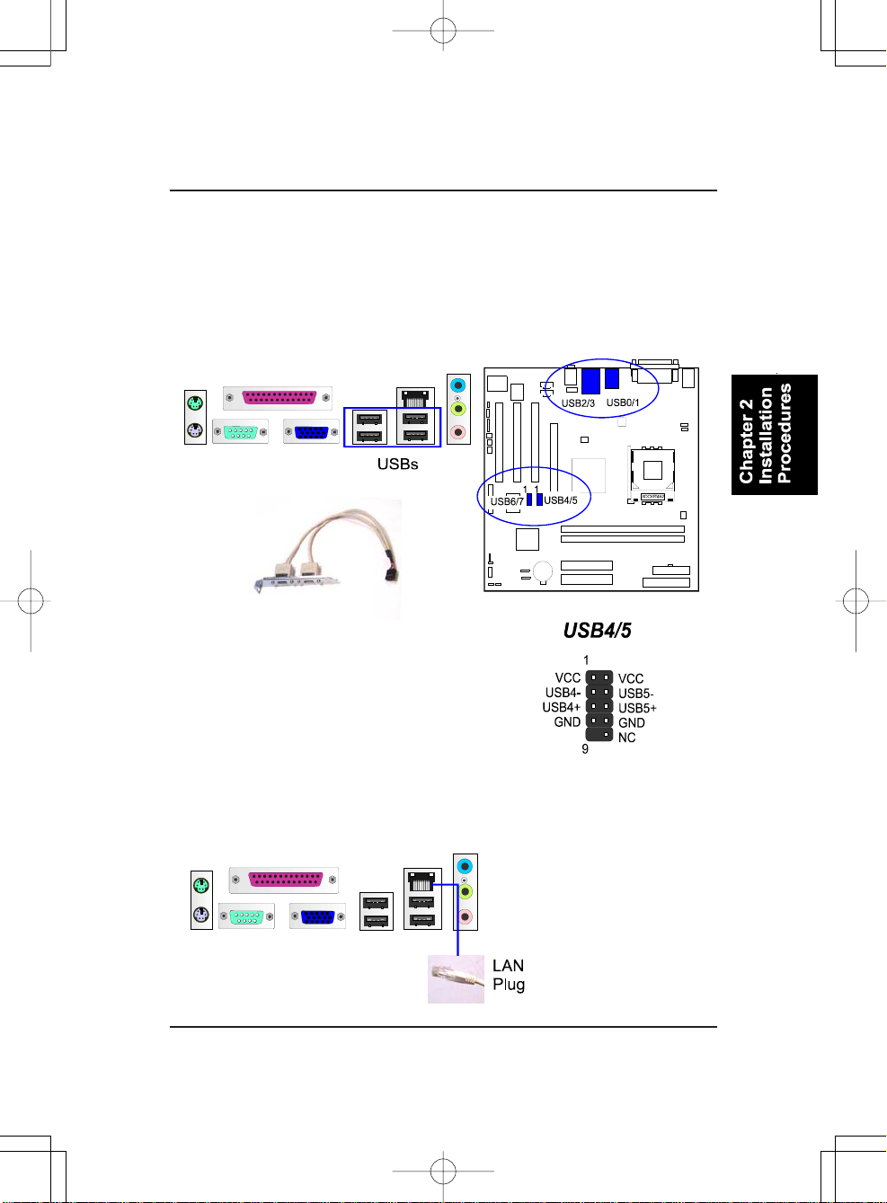
Universal Serial Bus Connectors
The mainbaord has six USB ports; four USB black jacks that are integrated on
the edge of the board, the other two USB pinheaders on the board. They
allows uses to attach to USB devices either from the rear or front panels. The
USB cable that comes with your mainboard is used to connecting between the
USB pinheaders and rear panel. (See the photo below).
The figure at right shows the pin assignments
of the USB4/5. Those of USB6/7 are similar.
RJ45 LAN Connector
The LAN (RJ45 port) jack is used f or the LAN cable plug.
2 - 17
Page 32
K7M-400A Mainboard Ma nual
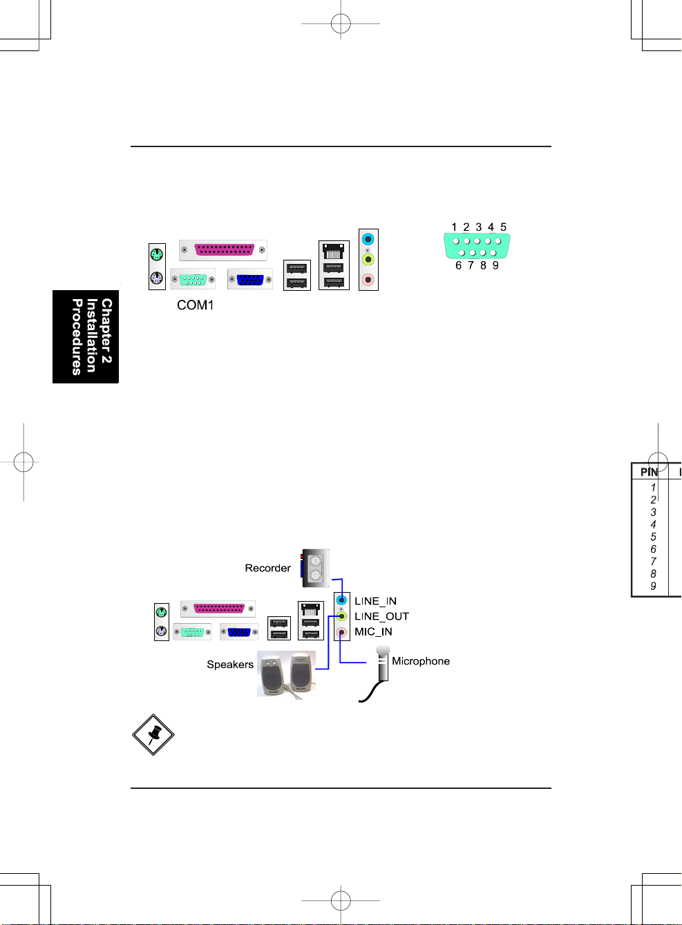
Serial Port Connector
COM1 (teal colored 9-pin D-sub male connector) allows you to connect with
your device that use a serial port, such as a seri al mouse or an external modem.
Audio I/O Jacks
LINE_OUT (lime) can be connected to headphones or preferably powered
speakers. LINE_IN (light blue) allows tape players or other audio sources to
be recorded by your computer or played through the LINE_OUT. MIC_IN
(pink) allows microphones to be connected for audio input.
2 - 18
NOTE: LINE_IN, LINE_OUT, and MICROPHONE jacks can be used
the 5.1-channel audio output with its software tool.
Page 33
Installation Procedures
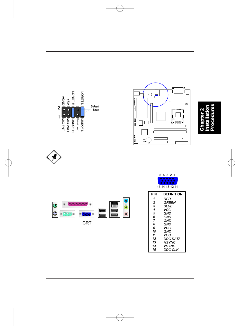
Front Audio Connector
The mainboard has a front panel audio F_AUDIO connector (Intel spec.). It
allows users to attach the audio device via the front panel (instead of the rear
panel) by a ribbon cable that in some cases.
Its pin definitions are resented below.
NOTE: If you do not use F_AUDIO, plea se keep the pinpair 5-6, 9-10
short as default; also, when the front headphone is plugged in,
the rear audio output will be disabled.
CRT Connector
This connector is linked to your monitor. The
pinheaders pin assignments are shown at right side.
2 - 19
Page 34
K7M-400A Mainboard Ma nual
This Page Left Blank for Note
2 - 20
Page 35
BIOS Setup
Chapter 3
BIOS Setup
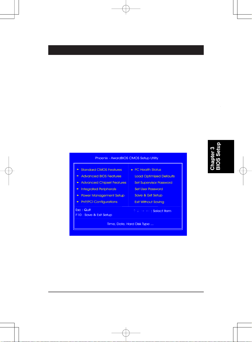
The mainboard comes with a chip from Award BIOS that contains the ROM
Setup information for your system. This chip serves as an interface between
the processor and the rest of the mainboard components. This section explains the information contained in the Setup program and tells you how to
modify the settings according to your system configuration.
CMOS Setup Utility
The Setup Utility program allows updates to the mainboard configuration
settings. The BIOS setup values will be saved in the CMOS. Setup is executed
when the user changes system configurations; changes the system backup
battery or the system detects a configuration error and asks the user to run the
Setup program. Use the arrow keys to select and press Enter to run the selected program.
3 - 1
Page 36
K7M-400A Mainboard Ma nual
Standard CMOS Setup
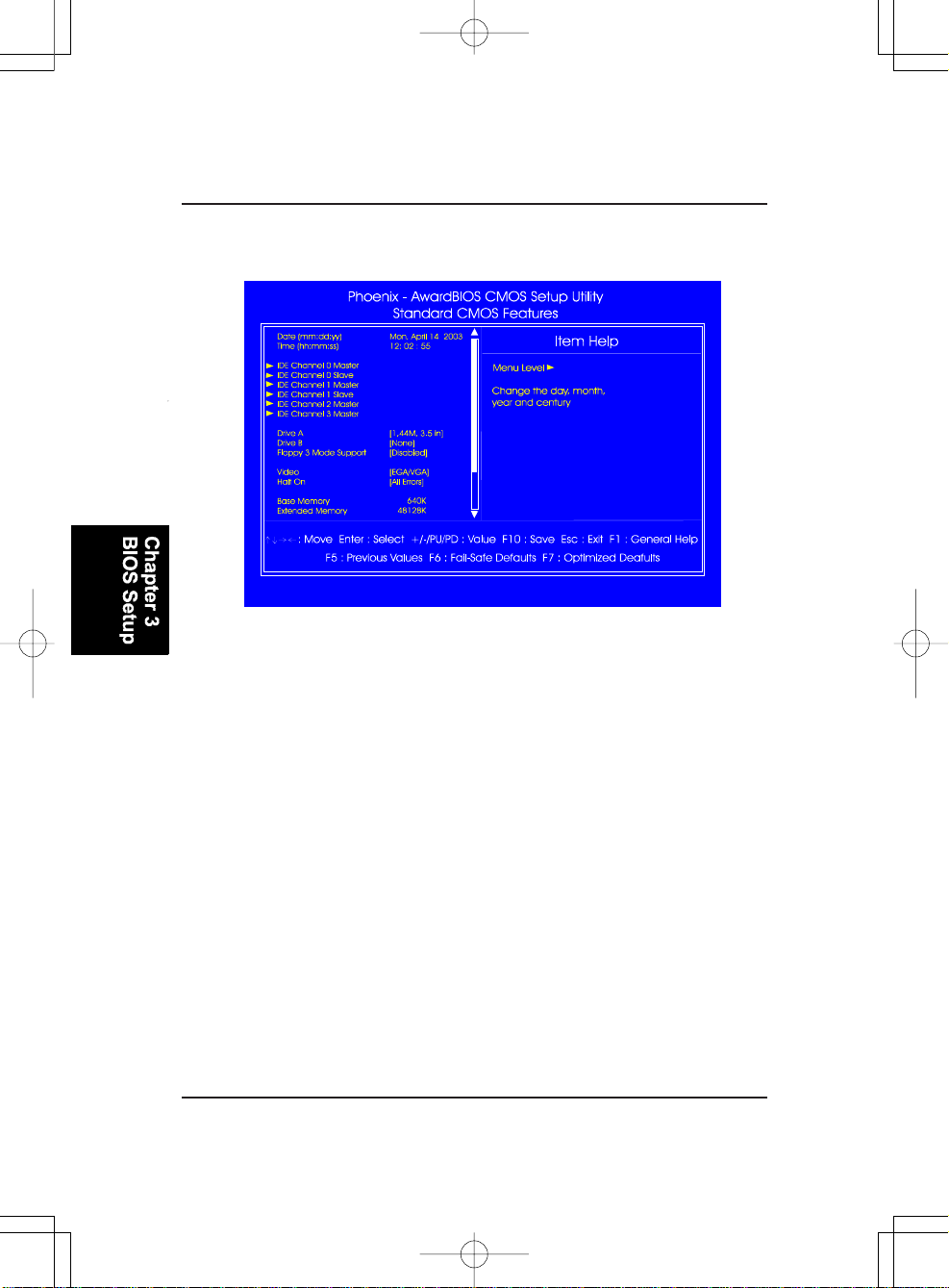
The Standard CMOS Setup screen is displayed above. Each item may have
one or more option settings. The system BIOS automatically detects memory
size, thus no changes are necessary. Use the arrow keys to highlight the item
and then use PgUp or PgDn keys to select the value you want in each item.
Date
T o set the date, highlight the Date field a nd then press Page Up/Page Down
or +/- keys to set the current date. Follow the month, day and year format.
Time
T o set the time, highlight the Time field a nd then press Page Up/Page Down
or +/- keys to set the current time. Follow the hour, minute, and second
format.
3 - 2
Page 37
BIOS Setup
Hard Disks
This field records the specifications for all non-SCSI hard drives installed
in the system. The onboard PCI IDE connectors provide Pri mary and Secondary channels for connecting up to four IDE hard disks or other IDE
devices. Each channel can support up to two hard disks, the first of which
is the Master and the second is the Slave.
Hard Disk Configurations
Capacity: The hard disk size. The unit is Bytes.
Cylinder: The cylinder number of the hard disk.
Head: The read/write head number at the hard disk.
Precomp: The cylinder number of which the disk drivechanges the
write current.
Landing Zone: The cylinder number on which the disk drive heads
(read/write) are seated when the disk drive is parked.
Sector: The sector number of each track defined on the hard
disk.
Drive A / Drive B
This field records the types of floppy drives installed in the system. To
enter the configuration value for a particular drive, highlight its corresponding field a nd then select the drive type using the left- or right-arro w
key.
Floppy 3 Mode Support
This is a Japanese standard floppy type drive.
Video
Set this field to the type of video display card installed in the system.
Halt On
This field determines which types of errors will cause the system to halt.
3 - 3
Page 38
K7M-400A Mainboard Ma nual
Advanced BIOS Features
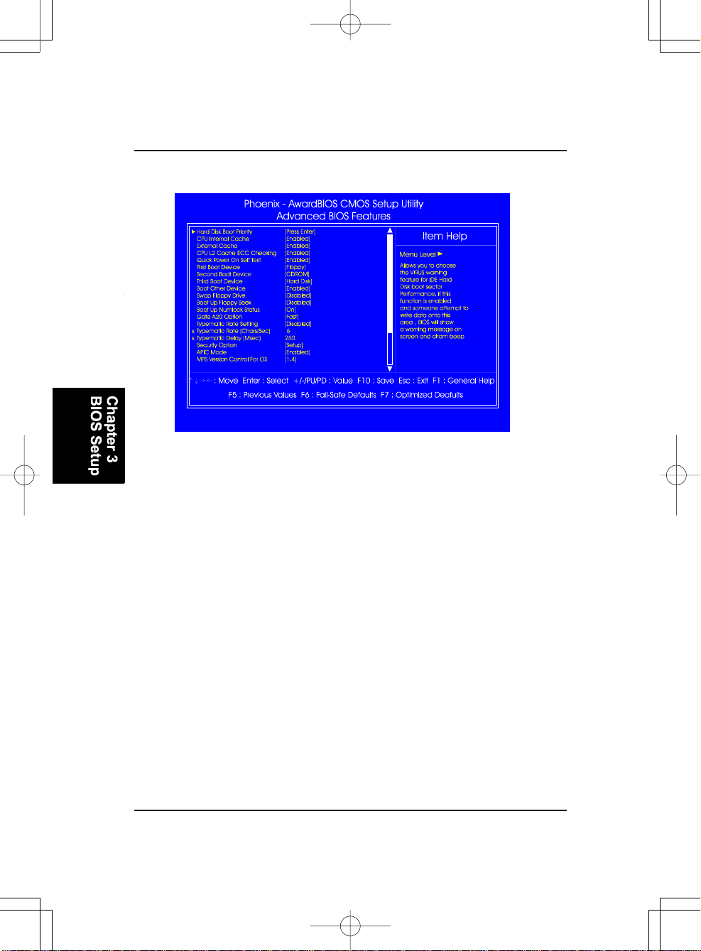
Hard Disk Boot Priority
This feature will auto detect all hard disks of bootable devices on the
system. It also allows you to select hard disk device booting priority.
CPU Internal Cache
This controls the status of the processor’s internal cache area.
The options are: Enabled, Disabled.
External Cache
This controls the status of the external (L2) cache area.
The options are: Enabled, Disabled.
CPU L2 Cache ECC Checking
Set the ECC (Error-Correcting Code) feature for Level 2 cache. Facilitates
error detection/correction when data passes through Level 2 cache.
The options are: Enabled, Disabled.
Quick Power On Self Test
When enabled, allows the BIOS to bypass the extensive memory test.
The options are: Enabled, Disabled.
3 - 4
Page 39
BIOS Setup
First/Second/Third Boot Device
This feature allows you to select the boot device priority.
The options are: Floppy, LS120, Hard Disk, CDROM, ZIP100, USB-FDD,
USB-ZIP , USB-CDROM, LAN, Disabled.
Boot Other Device
This feature allows you to select the boot device priority.
The options are: Enabled, Disabled.
Swap Floppy Drive
Allows you to switch the order in which the operating system accesses
the floppy drives during boot up. The options are: Enabled, Disabled.
Boot Up Floppy Seek
When enabled, assigns the BIOS to perform floppy diskette drive tests by
issuing the time-consuming seek commands.
The options are: Enabled, Disabled.
Boot Up Numlock Status
When set to On, allows the BIOS to automatically enable the Num Lock
Function when the system boots up. The options are: On, Off.
Gate A20 Option
When set at Fast, allows a faster access response under Protected mode.
The options are: Fast, Normal.
Typematic Rate Setting
The term typematic means that when a keyboard key is held down, the
character is repeatedly entered until the key is released.
The options are: Disabled, Enabled.
Typematic Rate (Chars/Sec)
This feature is available only if the above item, Type matic Rate Setting, is
set at Enabled. Sets the rate of a character repeat when the key is held
down. The options are: 6, 8, 10, 12, 15, 20, 24, 30.
3 - 5
Page 40
K7M-400A Mainboard Ma nual
Typematic Delay (Msec)
This feature is available only if the item, Typematic Rate Setting, is set at
Enabled. Sets the delay ti me before a character is repeated.
The options are: 250, 500, 750, 1000 millisecond.
Security Option
Allows you to set the security level of the system.The options: Setup,
System.
APIC Mode
Allows you to decide if the system enters the APIC (Advanced Programmable Interrupt Controller) mode or not for more IRQs can be released.
The options are: Enabled, Disabled.
MPS V ersion Control For OS
When two CPUs are onboard (not a feature of this board) this feature
allows you to select Multi-Processor Spec. (MPS) version control for OS
when the logo test executes. The options are: 1.1, 1.4.
OS Select For DRAM > 64MB
If your operating system (OS) is OS/2, select the option OS2. Otherwise,
stay with the default setting Non-OS2.The options are: Non-OS2, OS2.
HDD S.M.A.R.T. Capability
S.M.A.R.T. stands for Self-Monitoring and Analysis Reporting Technology which allows your hard disk drive to report any read/write errors and
issues a warning with LDCM installed. The options: Disabled, Enabled.
Video BIOS Shadow
Enabling this feature will copy the video BIOS to shadow RAM, it will
improve the system performance. The options are: Enabled, Disabled.
BIOS Guardian
It allows the system to prevent computer viruses. Users will need to disable it to update BIOS. The options are: Enabled, Disabled.
NOTE: Please disable the BIOS Guardian feature before you start
to reflash BIOS.
3 - 6
Page 41
BIOS Setup
BIOS Guardia n and Reflash BIOS
BIOS Guardi an by default is enabled, thus effectively a cting a s a firewall against viruses that can attack the BIOS while the system is
running. It must be disabled before you reflash BIOS.
The steps below show you how to turn the BIOS Guardi an off and on
when you want to reflash the BIOS:
1. Press Del key while booting a nd go to CMOS Setup Utility menu.
2. Go to the Advanced BIOS Features submenu.
3. Set the feature BIOS Guardian at Disabled.
4. Save the setting a nd exit. The system will restart.
5. The POST screen holds; A message about BIOS Guardi an shows.
6. Press the Space Bar.
7. Reflash the BIOS. Restart the system after you are finished.
8. The POST screen holds; A message about BIOS Guardi an shows.
9. Press G key. The feature, BIOS Guardi an, will be enabled again.
Full Screen LOGO Show
This decides whether or not the full screen logo is shown during system
boot ups. The options are: Enabled, Disabled.
Advanced Chipset Features
3 - 7
Page 42
K7M-400A Mainboard Ma nual
DRAM Clock/Drive Control
Current FSB Frequency , Current D RAM Frequency
This item allows you to get current FSB and DRAM frequencies.
DRAM Clock
The feature allows users to select the DRAM clock.
The options are: 133 MHz, 166 MHz, 200 MHz, By SPD.
DRAM Timing
This feature allows user to select the way to set DRAM timing.
The options are: Manual, Auto By SPD, Turbo, Ultra.
DRAM CAS Latency
If the CAS latency of your installed memory medule is 2 Cycle, The selection 2 will enha nce system perf ormance. The options are: 1.5, 2, 2.5, 3.
Bank Interleave
This item allows users to select the bank interleave function of DRAM,
when the feature DRAM Timing By SPD set at Disabled.
The options are: Disa bled, 2 Bank, 4 Bank.
Precharge to Active (T rp)
This item allows users to set the clock time from Precharge to Active command. The options are: 2T, 3T, 4T, 5T.
Active to Precharge (Tra s)
This item allows users to set the clock time from Active to Precharge command. The options are: 6T, 7T, 8T, 9T.
Active to CMD (Trcd)
This item allows users to set the clock time from Active to Read/Write
Delay comma nd. The options are: 2T, 3T, 4T, 5T.
DRAM Burst Length
This item allows users to set DRAM burst length.
The options are: 4, 8.
3 - 8
Page 43
BIOS Setup
DRAM Command Rate
This item allows users to set Address Time After command.
The options are: 2T Comma nd, l T Command.
Write Recovery Time
This item allows users to set write recovery time.
The options are: 2T, 3T.
tWTR
This item allows users to set DRAM tWTR timing control.
The options are: 2T, 1T.
AGP & P2P Bridge Control
AGP Aperture Size
It allows you to select the main memory frame size for AGP use.
The options list presents all provided possibilities.
AGP Mode
This feature allows users to select the AGP mode when an AGP add-on
card installed. The options are: 4X, 2X, 1X.
AGP Driving Control / AGP Driving Value
These two features allow user to improve the performance of AGP card
manually by pressing Page Down/Page UP key if necessary.
The options of AGP Driving Control are: Auto, M anual.
AGP Fast Write
This feature allows you to set AG P fast write mode.
The options are: Disabled, Enabled.
AGP Master 1 WS Write
When enabled, the AGP bus master write access to DRAMs will add one
wait-state cycle. The options are: Enabled, Disabled.
AGP Master 1 WS Read
When enabled, the AGP bus master read access to the DRAMs will add one
wait-state cycle. The options are: Disabled, Enabled.
3 - 9
Page 44
K7M-400A Mainboard Ma nual
AGP 3.0 Calibration cycle
This feature allows users to enable or disa ble AGP 3.0cablibration cycle.
The options are: Disabled, Enabled.
V G A Share Memory Size
It allows user to select the frame buffer size of VGA share me mory.
The options are: Disa bled, 16M, 32M, 64M.
CPU Direct Access FB
It allows user to enable or disable the direct access from CPU to frame
buffer of onboard video chip. The options are: Disabled, Enabled.
CPU & PCI Bus Control
PCI1/2 Master 0 WS Write
When enabled, allows a zero-wait-state-cycle delay when the PCI1/2 ma ster drive writes data to DRAM. The options are: Enabled, Disabled.
PCI1/2 Post Write
When enabled, allows the CPU to PCI1/2 master drive excute s post write.
The options are: Enabled, Disabled.AGP Ma ster 1 W S Write
When enabled, the AGP bus master write access to DRAMs will add one
wait-state cycle. The options are: Enabled, Disabled.
VLink 8X Support
Enables VLink 8X support.
The options are: Enabled, Disabled.
PCI Delay Transa ction
Enable this feature to abort the current PCI master cycle and to accept the
new PCI master request, it rea ccepts the original PCI ma ster and returns the
PCI data phase to the original PCI master.
The options are: Disabled, Enabled.
3 - 10
Page 45
BIOS Setup
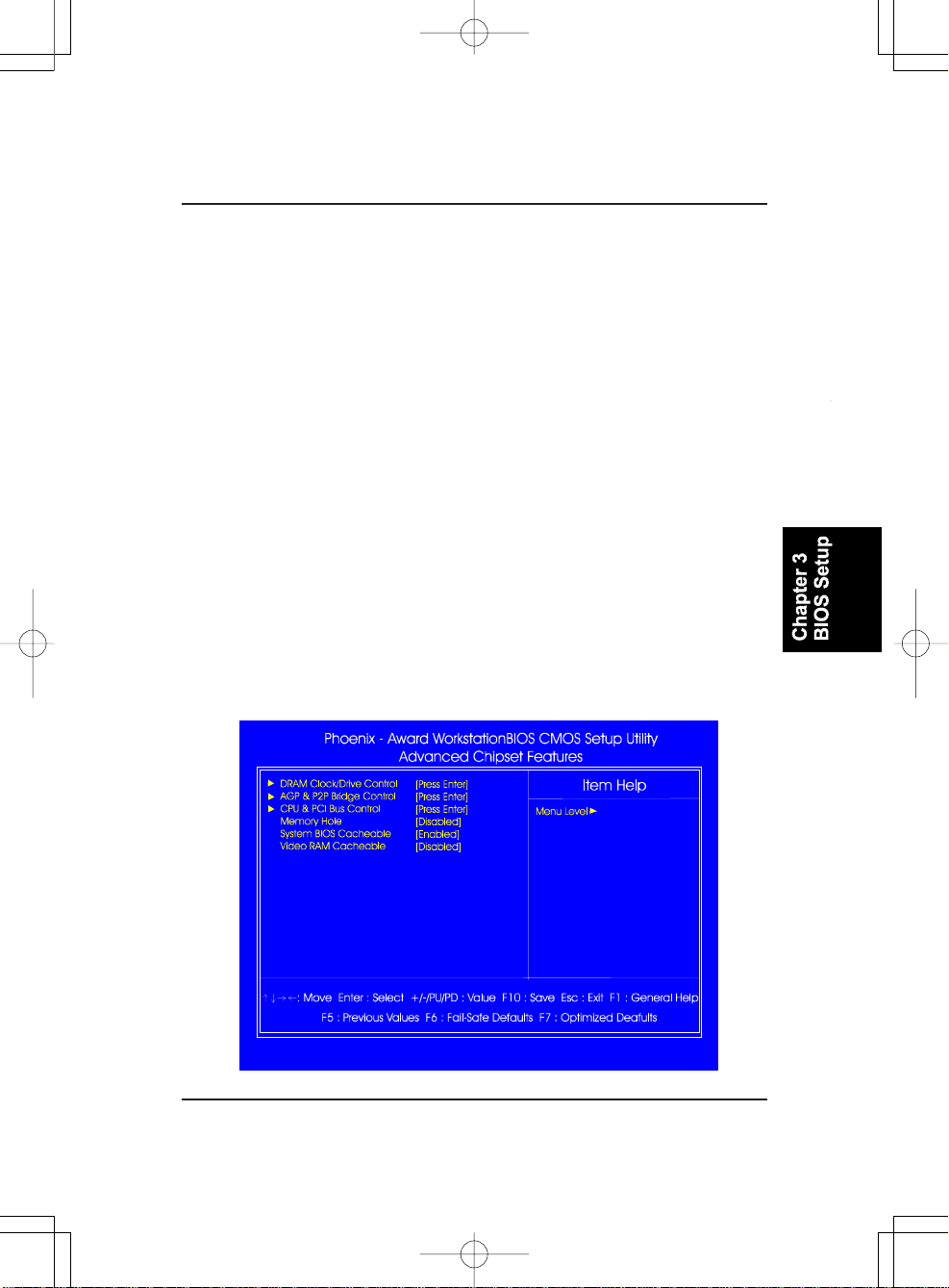
Memory Hole
When you install a Legacy ISA card, this feature allows you to select the
memory hole address range of the ISA cycle when the processor accesses
the selected address area. Please read your card ma nual f or detail inf ormation. When disabled, the memory hole at the (15-16MB) address will be
treated as a DRAM cycle when the processor accesses the15~16MB address area. The options are: 15M - 16M, Disabled.
System BIOS Cacheable
When enabled, allows the ROM area F000H-FFFFH to be cacheable when
cache controller is activated. The options are: Enabled, Disabled.
Video RAM Cachea ble
When enabled, allows the video RAM area to be cacheable.
The options are: Enabled, Disabled.
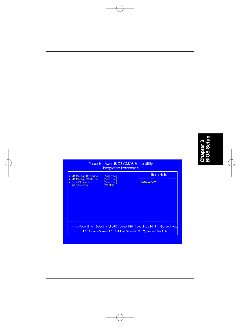
Integrated Peripherals
VIA OnChip IDE Device
OnChip SA T A
This item allows you to dia ble the seri al A TA controller embedded in South
Bridge. The options are: Auto, Disabled.
3 - 11
Page 46
K7M-400A Mainboard Ma nual
SA T A Mode
This item allows users to select the serial ATA mode
The options are: IDE, Raid.
IDE DMA trans fer access
This item allows users to disable the IDE DMA (Direct Memory Access)
transfer access function. The options are: Enabled, Disabled.
OnChip IDE Channel0/1
When enabled, this allows you to use the onboard pri mary/secondary PCI
IDE. The options are: Enabled, Disabled.
IDE Prefetch Mode
When set at Enabled, it allows data to be posted to and prefetched from the
primary IDE data ports. Data prefetching is initiated when a data port read
occurs. The rea d prefetch eli ments latency to the IDE data ports and allows
them to be performed ba ck to back for the highest possible PIO data transfer rates. The first data port read of a sector is called the demand read.
Subsequent data port reads from the sector are called prefetch reads. The
demand read a nd all prefetch reads must be of the same size (16 or 32 bits).
The options are: Enabled, Disabled.
Primary Ma ster/Slave PIO
Allows an automatic or a manual configuration of the PCI primary IDE
hard drive (master/slave) mode.
Secondary Ma ster/Slave PIO
Allows a n automatic or a manual configuration of the PCI secondary IDE
hard drive (master/slave) mode.
The options are: Auto, Mode 0, Mode 1, Mode 2, Mode 3, Mode 4.
Primary Ma ster/Slave UDMA
Allows an automatic configuration of the PCI primary IDE hard drive
(master/slave) mode if Ultra DMA is supported both on the motherboard
and the hard disk. The options are: Auto, Disabled.
3 - 12
Page 47
BIOS Setup
Secondary Ma ster/Slave UDMA
Allows an automatic configuration of the PCI secondary IDE hard drive
(master/slave) mode if Ultra DMA is supported both on the motherboard
and the hard disk. The options are: Auto, Disabled.
IDE HDD Block Mode
Block mode is also called block transfer, multiple commands, or multiple
sector read/write. If your IDE hard drive supports block mode (most new
drives do), select Enabled f or automatic detection of the opti mal number of
block read/writes per sector the drive can support.
The options are: Enabled, Disabled.
VIA OnChip PCI Device
VIA-3058 AC97 Audio
It allows users to disable AC97 audio function in South Bridge.
The options are: Auto, Disabled.
VIA-3043 Onchip LAN
It allows users to disable onboard LAN feature.
The options are: Enabled, Disabled.
Onboard Lan Boot ROM
Enables and disables the onboard LAN Boot ROM.
The options are: Enabled, Disabled.
Onboard 1394 Device
It allows users to disable the onboard 1394 feature.
The options are: Enabled, Disabled.
OnChip USB Controller
Disable this option if you are not using the onboard USB 1.1 and USB 2.0
feature. The options are: Disabled, Enabled.
OnChip USB2.0 Controller
It allows users to disable the onboard USB2.0 Enhanced Host Controller
Interface (EHCI) function. The options are: Enabled, Disabled.
3 - 13
Page 48
K7M-400A Mainboard Ma nual
USB Keyboard Support
Your system contains a Universal Serial Bus (USB) controller and you
have a USB keyboard Device. When set at Auto, the BIOS will detect if
USB keyboard is installed automatically.
The options are: Auto, Enabled, Disabled.
SuperIO Device
Onboard F DC Controller
When enabled, the floppy diskette drive (FDD) controller is activated.
The options are: Enabled, Disabled.
Onboard Serial Port 1
If the serial port 1 uses the onboard I/O controller, you can modify your
serial port parameters.
The options are: 3F8/IRQ4, 3E8/IRQ4, 2F8/IRQ3, 2E8/IRQ3, Disa bled.
IR Controller Port
Allows you to enable the IR function. The options are: Enabled, Disabled.
IR Mode Select
Allows you to select the IR modes. The options are: IrDA, ASKIR, SCR.
IR Duplex Mode
Allows you to select the IR modes. The options are: Full, Half.
Onboard Parallel Port
Allows you to select from a given set of parameters if the parallel port uses
the onboard I/O controller.
The options are: Disa bled, 378/IRQ7, 278/IRQ5, 3BC/IRQ7.
Parallel Port Mode
Allows you to connect with an advanced printer via the port mode it supports. The options are: SPP, ECP, EPP, EPP+ECP.
ECP Mode Use DMA
This feature allows you to select Direct Memory Access (DMA) channel.
The options are: 1, 3.
3 - 14
Page 49
BIOS Setup
Init Display First
When you install a n AGP VGA card a nd a PCI VGA card on the board, this
feature allows you to select which card the first initiation of the monitor
display comes from. The options are: PCI Slot, AGP.
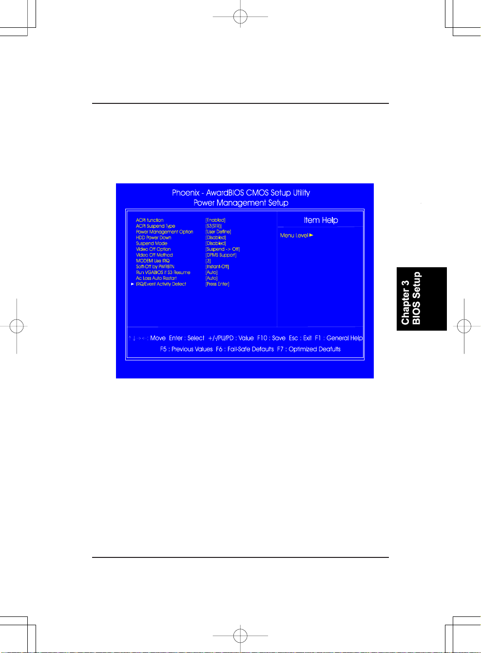
Power Management Setup
ACPI function
This item allows you to disable the ACPI function.
The options are: Enabled, Disabled.
ACPI Suspend T ype
This item allows you to select suspend mode when the system is in ACPI
mode. The options are: S1 (POS), S3 (PTR), S1&S3.
Power Management Option
This item allows you to adjust the power management features.
Select User Define for configuring your own power ma nage ment features.
Min Saving initiates all predefined timers in their minimum values. Max
Saving, on the other hand, initiates maximum values.
The options are: User Define, Min Saving, Max Saving.
3 - 15
Page 50
K7M-400A Mainboard Ma nual
HDD Power Down
This option lets the BIOS turn the HDD motor off when the systemis in
Suspend mode. Selecting 1 Min,..,15 Min allows you to define the HDD
idle time before the HDD enters the Power Saving Mode.
The options 1 Min,..,15 Min will not work concurrently. When HDD is in
the Power Saving Mode, a ny access to the HDD will wake the HDD up.
The options are: Disa bled, 1 Min,..,15 Min.
Suspend Mode
When disabled, the system will not enter Suspend mode. The specified
time option defines the idle time the system takes before it enters Suspend
mode. The options are: Disable, 1, 2, 4, 8, 10, 20, 30, 40 M in, 1 Hour.
Video Off Option
This feature provides the selections of the video display power saving
mode. The option Suspend - Off allows the video display to go blank if the
system enters Suspend mode. The option All Modes - Of f allows the video
display to go bla nk if the syste m enters Doze mode or Suspend mode. The
option Always On allows the video display to stay in Standby mode even
when the system enters Doze or Suspend mode.
The options are: Suspend - Off, All Modes -> Off, Always On.
Video Off Method
The option V/H SYNC+Blank allows the BIOS to blank off screen display
by turning off the V-Sync and H-Sync signals sent from add-on V GA card.
DPMS Support allows the BIOS to bla nk off screen display by your add-on
VGA card which supports DPMS (Display Power Management Signaling
function). Blank Screen allows the BIOS to blank off screen display by
turning off the red-green-blue signals.
The options are: V/H SYNC+Bla nk, DPMS Support, Blank Screen.
MODEM Use IRQ
This feature allows you to select the IRQ# to meet your modem IRQ#.
The options are: NA, 3, 4, 5, 7, 9, 10, 1 1.
3 - 16
Page 51
BIOS Setup
Soft-Off by PWRBTN
The selection Delay 4 Sec. will allow the syste m shut down after 4 seconds
after the power button is pressed. The selection Instant-Off will allow the
system shut down immediately once the power button is pressed.
The settings are: Delay 4 Sec, Instant-Off.
Run V GABIOS if S3 Resume
This feature allows you to decide the way that VGA BIOS should be called
when the system resumes from an S3 state, if the above feature is set at S3
(PTR) or S1&S3. The options are Auto, Yes, No.
Ac Loss Auto Restart
When the system is shut down owing to the power failure, the system will
not be back to power on by itself. This feature allows you to set the
system back to which power status of the system when the system power
is resumed. It always will be back to on if set at On. The system always be
back to off if set at Of f. The options are Auto, On, Of f.
IRQ/Event Activity Detect
USB Resume from S1-S3
This item allows you to wake-up the system by USB device when you save
the computer power at S1-S3. The options are: Enabled, Disabled.
PowerOn by PCI Card
When set at Enabled, any PCI-PM event awakes the system from a PCI-PM
controlled state. The options are Disabled, Enabled.
Modem Ring Resume
An input signal on the serial Ring Indicator (RI) line (in other words, an
incoming call on the modem) awakens the system from a soft off state.
The options are: Enabled, Disabled.
RTC Alarm Resume
Enabled allows you to set the time the system will be turned on from the
system power-off status. The options are: Enabled, Disabled.
Date (of Month)
This feature allows you to set the day of the alarm starts when the RTC
Alarm Resume From Soft Off is set to be Enabled. The options are: 0, 1..31.
3 - 17
Page 52
K7M-400A Mainboard Ma nual
Resume Time (hh:mm:ss)
If a n ATX power supply is installed a nd when R TC Alarm Resume is Ena bled,
this feature allows you to set the time of the alarm starts when the RTC
Alarm Resume From Soft Off is set to be Enabled.
The options are: hh (hour) - 0, 1, 2,.., 23; mm (minute) - 0, 1, 2,..,59; ss
(second) - 0, 1, 2,..,59.
IRQs Activity Monitoring
Primary INTR
If set at ON, the Primary interrupt (the Primary option in the feature of IRQ#
Acitivity) will make the power ma nagement wake up the syste m.
The options are: ON, OFF.
IRQs 3-15
Allows you to set system to monitor IRQs 3-15 for activity to awaken
system from a power ma nage ment mode.
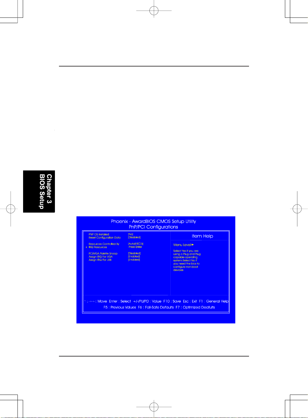
PnP/PCI Configurations
PNP OS Installed
If your operating system supports Plug-and-Play, such as Windows NT,
Windows 95, select Yes. The options are: No, Yes.
3 - 18
Page 53
BIOS Setup
Reset Configuration Data
Enabling this, resets the system Extended System Configuration Data
(ESCD) when you exit Setup, if you have installed a new add-on card and
the system reconfiguration has caused such a serious conflict that the
operating system can not boot. The options are: Disabled, Enabled.
Resources Controlled By
If set at Auto, the BIOS arranges all system resources. If there exists a
conflict, select Manual. The options are: Auto (ESCD), Manual.
If manual is chosen, after the feature IRQ Resources is pre ssed, the IRQ-
Assigned To are: PCI Device, Reserved. When resources are controlled
manually, assign each system interrupt a type, depending on which device
type uses the interrupt.
PCI/V GA Palette Snoop
Set this feature to be enabled if any ISA a da pter card installed in the syste m
requires the VGA palette snoop function.
The options are: Disabled, Enabled.
Assign IRQ For VGA
If your PCI VGA card devices do not need a n IRQ, select Disabled; therefore, an IRQ can be released for the system use.
The options are: Enabled, Disabled.
Assign IRQ For USB
If your USB devices do not need a n IRQ, select Disa bled; therefore, an IRQ
can be released for the system use.
The options are: Enabled, Disabled.
3 - 19
Page 54
K7M-400A Mainboard Ma nual
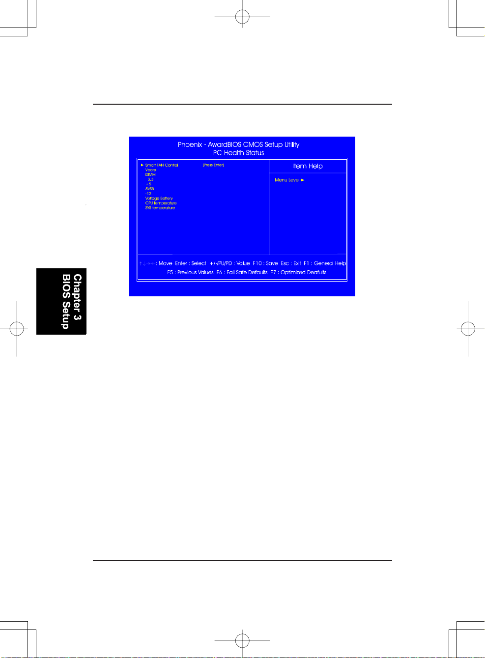
PC Health Status
Smart FAN Control
This feature allows users to configure parameters of cooling fans.
The rest of the items allow end users and technicians to monitor data provided
by the BIOS on this mainboard. They are not user-configura ble.
Load Optimized Defaults
This submenu is selected for default settings which provide the best system
performance.
Supervisor/User Password
To enable the Supervisor/User passwords, select the item from the Standard
CMOS Setup. You will be prompted to create your own password. Type your
password up to eight characters a nd pre ss Enter. You will be asked to confirm
the password. Type the password again and press Enter. To disable the
password, press Enter twice when you are prompted to enter a password. A
message appears, confirming the password is disabled.
3 - 20
Page 55
BIOS Setup
Under the BIOS Feature Setup, if Setup is selected under the Security Option
field a nd the Supervisor/User Pa ssword is ena bled, you will be prompted f or a
password every time you try to enter the CMOS Setup Utility. If System is
selected and the Supervisor/User Password is enabled, you will be requested
to enter the Password every time you reboot the system or enter the CMOS
Setup utility.
Save and Exit Setup
After you have made changes under Setup, press Esc to return to the main
menu. Move the cursor to Save a nd Exit Setup or press F10 and then press Y to
change the CMOS Setup. If you did not change anything, press Esc again or
move the cursor to Exit W ithout Saving a nd pre ss Y to retain the Setup settings.
The following message will appear at the center of the screen to allow you to
save data to CMOS a nd exit the setup utility: SA VE to CMOS a nd EXIT (Y/N)?
Exit without Saving
If you select this feature, the following message will appear at the center of the
screen to allow you to exit the setup utility without saving CMOS modifications:
Quit Without Saving (Y/N)?
3 - 21
Page 56
K7M-400A Mainboard Ma nual
This Page Left Blank for Notes
3 - 22
Page 57
Kurzanleitung
Bevor Sie beginnen
Diese Kurzanleitung zusammen mit dem EZ-Handbuch unterstützt Sie bei der
Installation des Computersystems. Details entnehmen Sie bitte dem Handbuch.
1.
Statische Elektrizität kann die integrierten
Schaltungen auf dem Motherboard beschädigen.
Bevor Sie ein Motherboard aus seiner Schützhülle
herausnehmen, sollten Sie sicherstellen, dass sich
keine statische Elektrizität auf Ihrem Körper befindet.
2.
Betreiben Sie den Prozessor nie ohne richtig und fest
angebrachtem Kühlkörper. EINE PERMANENTE
BESCHÄDIGUNG IST DIE FOLGE!
Prüfen des Kartoninhalts
Müssen Sie feststellen, dass eines der folgenden Gegenstände beschädigt ist
oder fehlt, dann kontaktieren Sie bitte Ihre Verkaufsstelle.
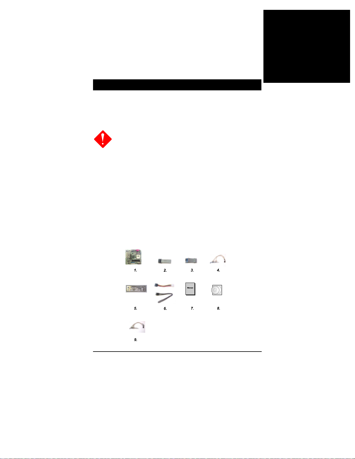
1. Mainboard 2. Kabel des Diskettenlaufwerks 3. 40-pol. IDE-Flachbandkabel
4. USB-Kabel 5. E/A-Abschirmung 6. 2 SATA-Kabel (optional) 7. Anleitung 8.
Treiber 9. 1394-Kabel (optional)
Deutsch
1
Page 58
Deutsch
Handbuch
Installation der Hardware
CPU
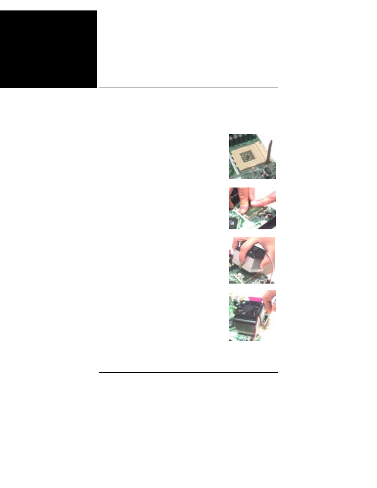
1. Ziehen Sie den Hebel bis 90 Grad nach oben.
2. Installieren Sie die CPU und achten Sie dabei
darauf, das der Stift 1 mit der Markierung auf der
Sockelecke, die der Hebelspitze am nächsten
liegt, ausgerichtet ist. Stecken Sie die CPU nicht
gewaltsam hinein.
Tragen Sie auf der CPU einige thermische
Materialien auf; installieren Sie auch einen Lüfter
mit Kühlkörper, der vom CPU-Hersteller
genehmigt ist. Befestigen Sie die CPU, indem
Sie den Hebel herunterdrücken und sie dadurch
verriegeln.
3. Legen Sie den Lüfter mit Kühlkörper auf die
CPU und drücken Sie die zwei Plastikklemmen
herunter, damit sie in die Löcher auf beiden
Seiten des Retentionsmoduls einhaken.
4. Drücken Sie weiße Leiste auf jedem Clip nach
unten, um das Lüfterset am Retentionsmodul zu
befestigen.
2
Page 59
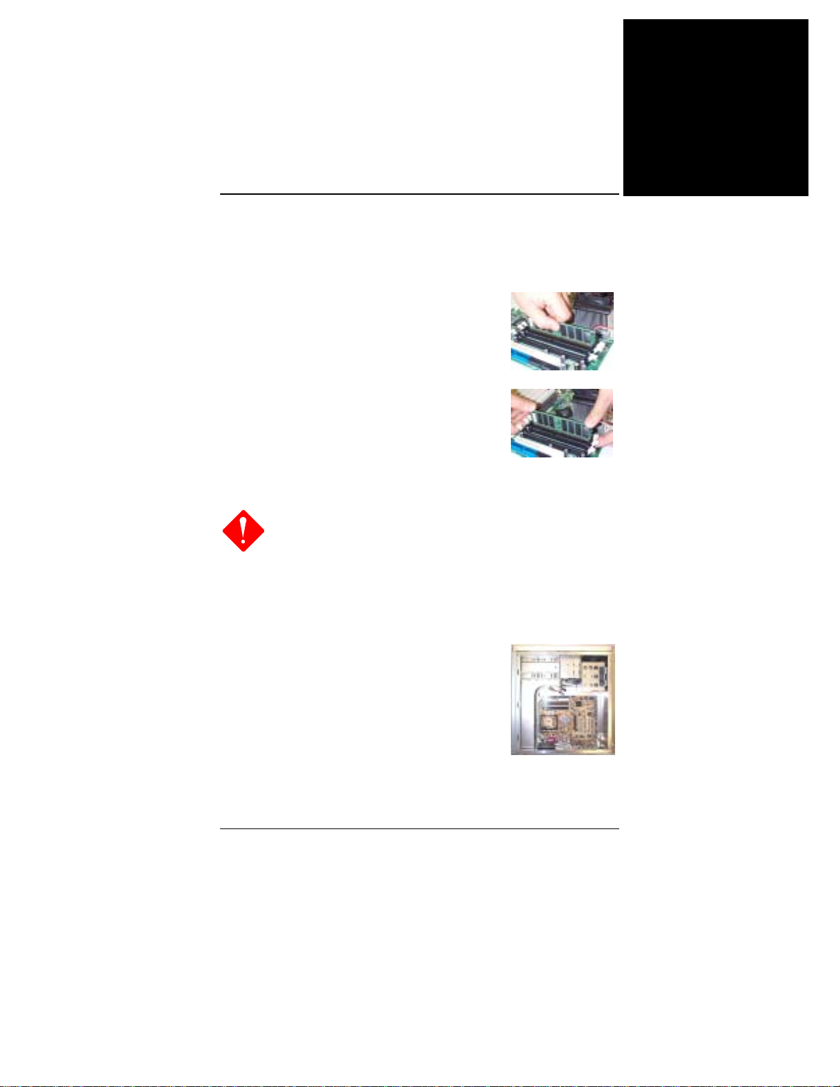
Arbeitsspeicher
1. Finden Sie die DDR-DIMM-Sockel auf dem
Mainboard.
2. Stecken Sie das DDR-DIMM mit beiden
Händen gerade nach unten in den Sockel 1
hinein, dann in Sockel 2, usw.
3. Die Klemme an beiden Enden des Sockels
schließt sich, um das DDR-DIMM festzuhalten,
wenn das DDR-DIMM den Sockelboden
erreicht.
Einbauen des Mainboards
1.
Bei Verwendung eines elektrischen Schraubenziehers
sollten Sie das Drehmoment auf 5,0 ~ 8,0 kg/cm
einstellen.
2.
Achten Sie auf scharfe Gerätekanten.
1. Finden Sie die Befestigungslöcher auf dem
Mainboard.
2. Legen Sie das Mainboard auf den Rahmen im
Gehäuseinnern. Achten Sie darauf, dass das
Mainboard und der Rahmen miteinander
ausgerichtet sind.
Kurzanleitung
Deutsch
3. Befestigen Sie das Mainboard mit
Kupferstützen.
3
Page 60
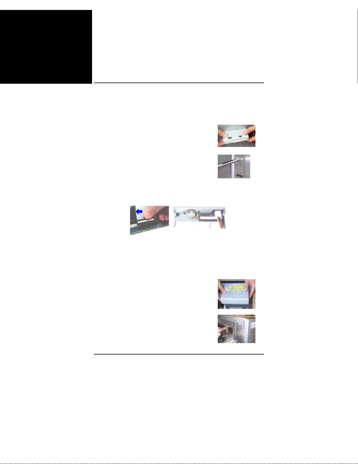
Deutsch
Handbuch
Anschließen von Geräten
1. Finden Sie den Rahmen und die Aufnahme des
Diskettenlaufwerks am Gehäuse.
2. Schieben Sie das Laufwerk von der
Vorderseite in den Rahmen hinein.
3. Befestigen Sie das Laufwerk mit Schrauben
am Rahmen.
4. Schließen Sie das Flachbandkabel und die Leitungsdrähte des
Diskettenlaufwerks an. Die farbige Linie auf dem Flachbandkabel (mit
blauem Pfeilkopf) muss sich auf der gleichen Seite befinden, wie Stift
1 des Anschlusses.
Anschließen eines CD/DVD-Laufwerks
1. Finden Sie den Rahmen und die Aufnahme des CD/DVDLaufwerks am Gehäuse.
2. Schieben Sie das Laufwerk von der
Vorderseite in den Rahmen hinein.
3. Befestigen Sie das Laufwerk mit Schrauben
am Rahmen.
4
Page 61
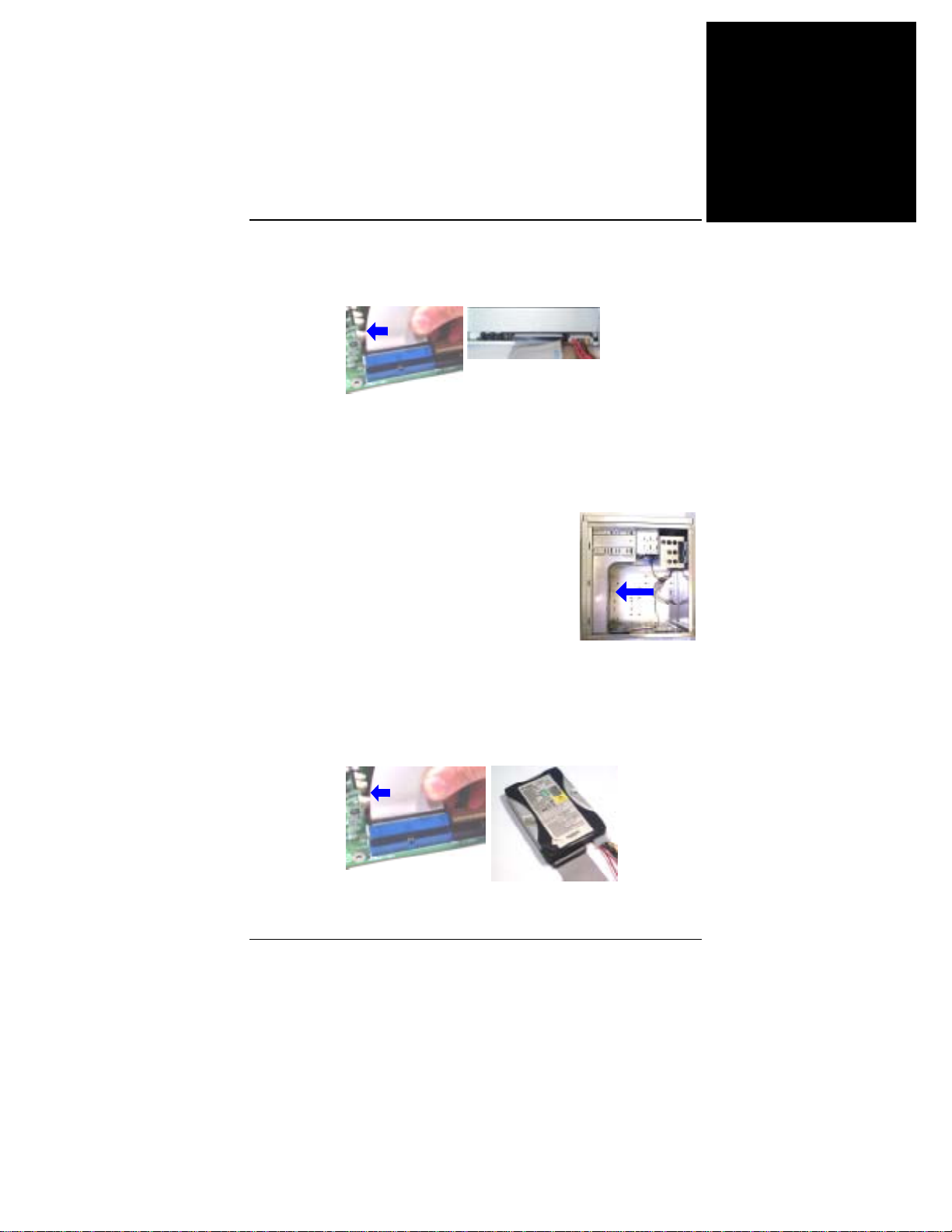
Kurzanleitung
4. Schließen Sie das IDE-Flachbandkabel und die Leitungsdrähte an.
Die farbige Linie auf dem Flachbandkabel (mit blauem Pfeilkopf)
muss sich auf der gleichen Seite befinden, wie Stift 1 des Anschlusses.
Anschließen einer Festplatte
1. Finden Sie den Rahmen und die Aufnahme der Festplatte am
Gehäuse.
2. Schieben Sie die Festplatte von der Rückseite
des Rahmens hinein, wie der Pfeilkopf anzeigt.
Deutsch
3. Befestigen Sie das Laufwerk mit Schrauben
am Rahmen.
4. Schließen Sie das IDE-Flachbandkabel und die Leitungsdrähte an.
Die farbige Linie auf dem Flachbandkabel (mit blauem Pfeilkopf)
muss sich auf der gleichen Seite befinden, wie Stift 1 des Anschlusses.
5
Page 62
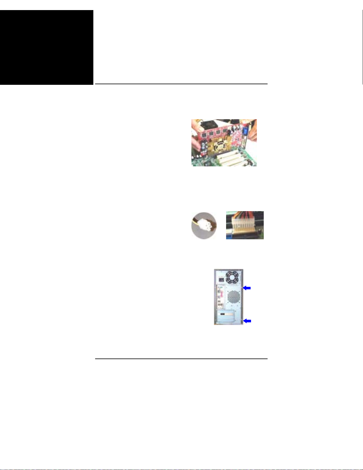
Deutsch
Handbuch
Installieren von Karten
1. Wählen Sie einen verfügbaren Kartensteckplatz aus.
2. Entfernen Sie die Abdeckung des
Steckplatzes vom Gehäuse.
3. Stecken Sie die Karte fest in den Steckplatz hinein. Befestigen Sie
die Karte mit der Schraube.
Anschließen des ATX-Netzteils
Der Netzstecker mit 20 Löchern wird
mit dem ATX-Netzanschluss
verbunden. Der Netzstecker mit 4
Löchern wird mit dem ATX_12VNetzanschluss verbunden.
Montieren des Systemgehäuses
Setzen Sie die Abdeckung auf das
Gehäuse und ziehen Sie die
Schrauben auf dem Gehäuse (in
Pfeilrichtung) mit einem
Schraubenzieher oder mit Ihren
Fingern fest an.
6
Page 63

Kurzanleitung
Anschließen von Peripheriegeräten
Schließen Sie Peripheriegeräte über die Rück-/Vorderseite an Ihr
System an.
Deutsch
System-
Netzkabel
PS/2-Tastatur
USB-Flasch-
Speichermodul
Joystick
BIOS-Setup
PS/2-Maus
Drucker
Monitor
Zur LAN-Buchse
Lautsprecher
7
Page 64
Deutsch
Handbuch
Standard CMOS Setup
Markieren Sie den Menüpunkt mit den Pfeiltasten und wählen Sie den
Wert für jeden Punkt mit den Tasten Bild-Nach-oben oder Bild-Nachunten aus.
Load Fail-Safe Defaults
Dieses Untermenü dient zur Diagnose des Computers, wenn er nicht
richtig startet. Diese Einstellungen liefern keine optimale
Systemleistung.
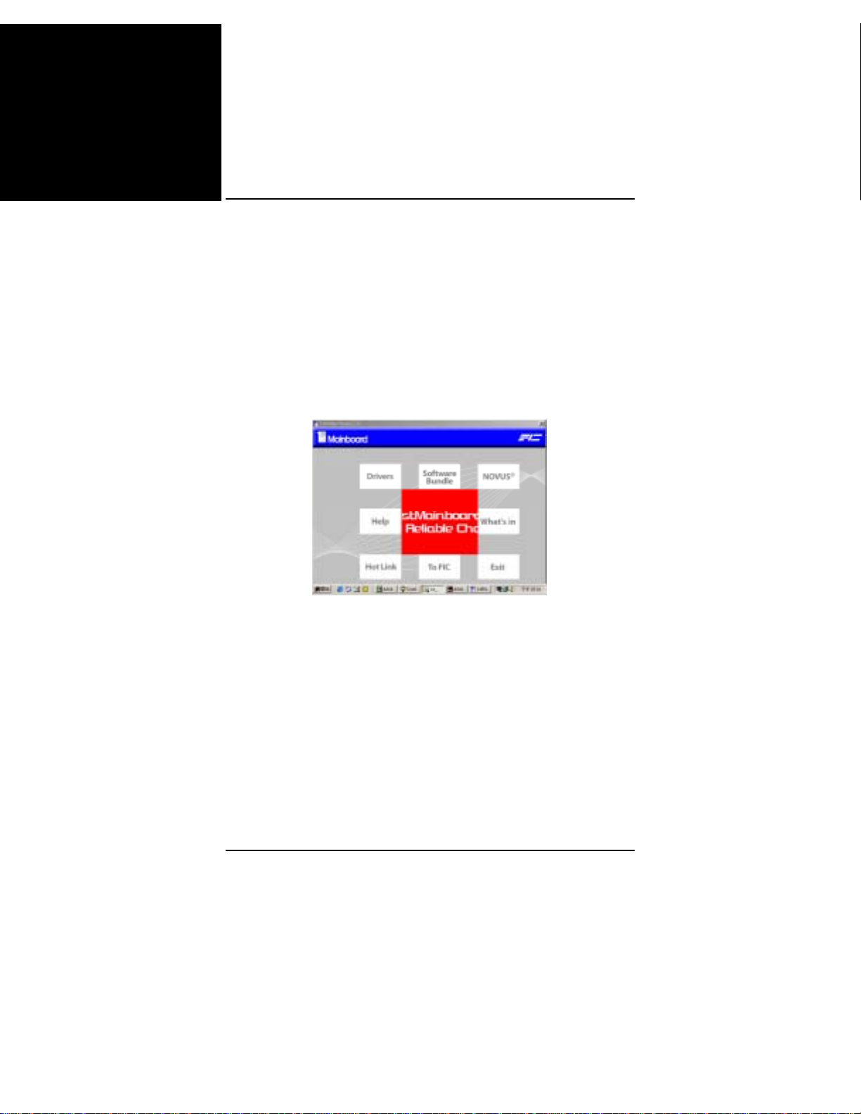
Treiberinstallation
Drivers
Legen Sie die 1. Utility-CD in das CD-Laufwerk. Das obere Menü
erscheint im Bildschirm. Wählen Sie den Punkt Drivers, um die
automatische Treiberinstallation einzuleiten.
Help
Dieser Punkt informiert Sie über die Funktionen und die Treiber. Er ist
sehr hilfreich bei der Installation.
Software Bundle
Dieser Punkt verfügt über einige nützliche Software-Werkzeuge, die
Sie bei der Verwaltung Ihres Computersystems unterstützen.
8
Page 65
Guide de référence rapide
Avant de commencer
Le présent guide de référence facile et le guide EZ ont pour but de vous aider à
installer votre système informatique. Pour des informations plus détaillées,
veuillez vous reporter au manuel de l'utilisateur.
1.
L'électricité statique risque d'endommager les circuits
intégrés sur la carte mère. Avant de sortir une carte
mère de son emballage protecteur, vérifiez que vous
n'êtes pas porteur d'une charge d'électricité statique.
2.
Ne jamais utilisé le processeur sans avoir installé
correctement et solidement un dissipateur de chaleur.
CELA RISQUERAIT DE CAUSER DES
DOMMAGES IRREVERSIBLES !
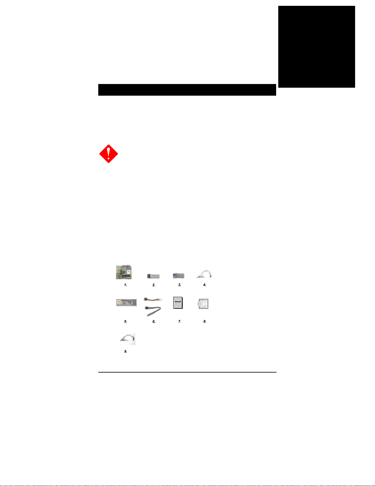
Liste de contrôle du paquet
Si vous vous rendez compte que l'un de ces éléments est manquant ou endommagé,
prenez immédiatement contact avec votre revendeur.
1. Carte mere 2. Câble pour lecteur de disquettes 3. Câble ruban IDE 80 broches
4. Câble USB 5. Protection E/S 6. Câble SATA (optionnel)7. Manuel 8. Pilotes 9. Câble
1394 (optionnel)
Français
1
Page 66
Français
Manuel de la carte mère
Installation de l'équipement
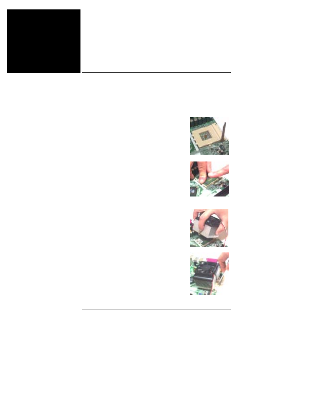
Microprocesseur :
1. Faites pivoter le levier vers le haut de 90
degrés.
2. Installez le microprocesseur et vérifiez
l'orientation de la broche 1 en alignant le coin
marqué du socle avec le coin du socle le plus près
de la pointe du levier. Ne pas forcer lors de
l'insertion du microprocesseur.
Appliquez des matériaux thermiques au sommet
du microprocesseur ; et installez un ventilateur
avec dissipateur de chaleur agréé par le fabricant
du microprocesseur. Fixez le microprocesseur en
position en abaissant le levier et en le
verrouillant.
3. Placez le ventilateur avec dissipateur de
chaleur sur le microprocesseur et appuyez sur les
deux clips en plastique pour les enclencher dans
les orifices sur le module de rétention sur les
deux côtés.
4. Appuyez sur la barre blanche sur chaque clips
pour fixer l'ensemble de ventilation sur le module
de rétention.
2
Page 67
Guide de référence rapide
Mémoire
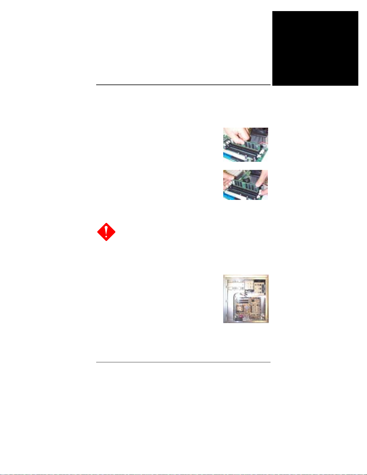
1. Repérez les emplacements DDR DIMM sur la carte
mère.
2. Installez un module DDR DIMM directement
dans le socle 1 en vous servant de vos deux
mains, puis dans le socle 2, et ainsi de suite.
3. Les clips situés aux deux extrémités du socle
se refermeront pour maintenir le module DDR
DIMM en position lorsque le module DDR
DIMM atteindra la base du socle.
Montage de la carte mère
1.
Lorsque vous utilisez un tournevis électrique, la
torsion doit être réglée entre 5,0 et 8,0kg/cm.
2.
Faites attention aux bords tranchants des éléments.
1. Repérez les orifices de montage sur la carte
mère.
2. Placez la carte au-dessus du cadre dans la
châssis. Vérifiez que la carte et le cadre sont bien
alignés.
Français
3. Fixez la carte mère à l'aide des plots en cuivre.
3
Page 68
Français
Manuel de la carte mère
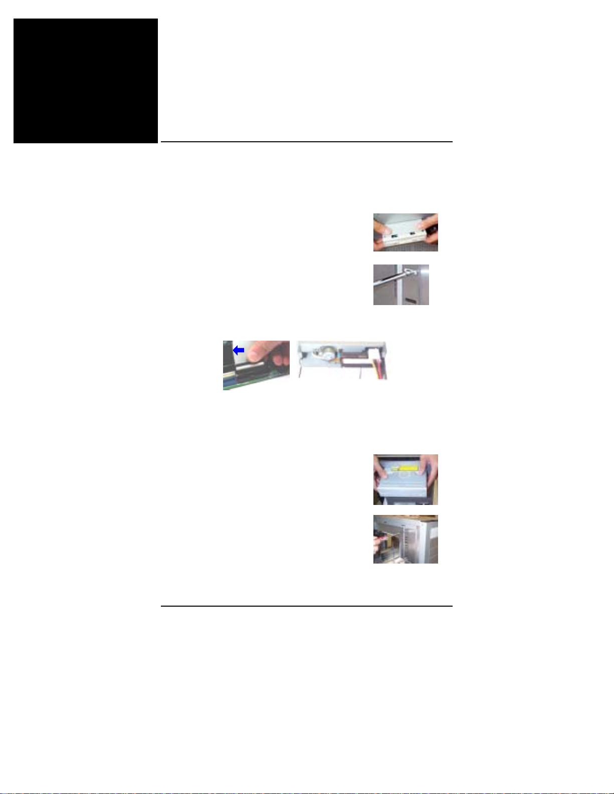
Branchement de périphériques
1. Repérez le cadre pour lecteur de disquettes et pour
disque dur sur le châssis.
2. Placez l'unité dans le cadre en l'insérant par le
panneau avant.
3. Fixez l'unité sur le cadre avec des vis.
4. Connectez le câble ruban et les fils d'alimentation du lecteur de
disquettes. La ligne colorée du câble ruban (indiquée par une flèche
bleue) doit être du même côté que la broche 1 du connecteur.
Connexion d'un lecteur de CD/DVD
1. Repérez le cadre pour unité CD/DVD sur le châssis.
2. Placez l'unité dans le cadre en l'insérant par le
panneau avant.
3. Fixez l'unité sur le cadre avec des vis.
4
Page 69
Guide de référence rapide
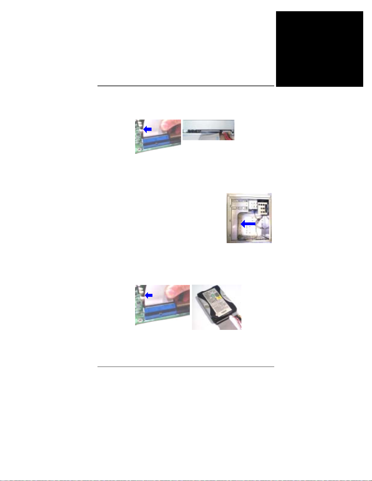
4. Connectez le câble ruban IDE et les fils d'alimentation. La ligne
colorée du câble (indiquée par une flèche bleue) doit être du même
côté que la broche 1 du connecteur.
Connexion du Disque dur
1. Repérez le cadre pour unité de disque dur sur le châssis.
2. Placez le disque dur en l'insérant à l'arrière du
cadre ainsi qu'indiqué par la flèche.
Français
3. Fixez l'unité sur le cadre avec des vis.
4. Connectez le câble ruban IDE et les fils d'alimentation. La ligne
colorée du câble (indiquée par une flèche bleue) doit être du même
côté que la broche 1 du connecteur.
5
Page 70

Français
Manuel de la carte mère
Installation des cartes
1. Sélectionnez un emplacement disponible pour carte.
2. Démontez le capot d'emplacement
du châssis.
3. Poussez fermement la carte dans l'emplacement. Fixez la carte
avec la vis.
Connexion de l'unité d'alimentation ATX
La prise d'alimentation 20 orifices
sert à connecter le connecteur de
l'unité d'alimentation ATX. La prise
d'alimentation 4 orifices sert à
brancher le connecteur
d'alimentation ATX_12V.
Montage du boîtier système
Placez le capot sur le châssis et fixez
à l'aide des vis sur le capot (ainsi
qu'indiqué par les flèches), soit avec
un tournevis soit avec les doigts, et
serrez-les.
6
Page 71
Guide de référence rapide
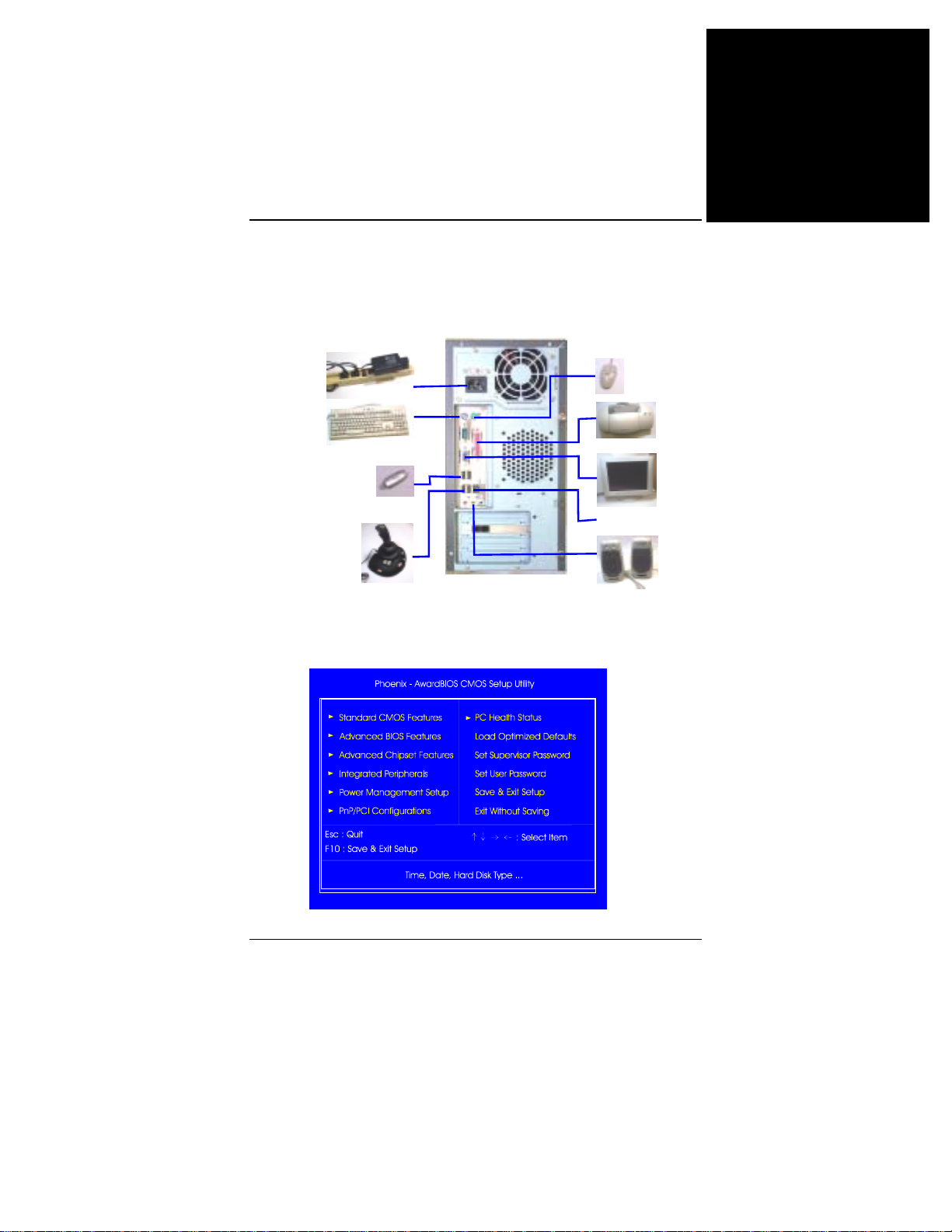
Branchement d'équipements périphériques
Vous pouvez brancher des équipements périphériques sur le
panneau arrière ou avant de votre système.
Français
Câble
alimentation
système
Clavier PS/2
Module mémoire
flash USB
Manette de
jeux
Configuration BIOS
Sur prise LAN
Souris
PS/2
Imprimante
Moniteur
Haut-parleurs
7
Page 72
Français
Manuel de la carte mère
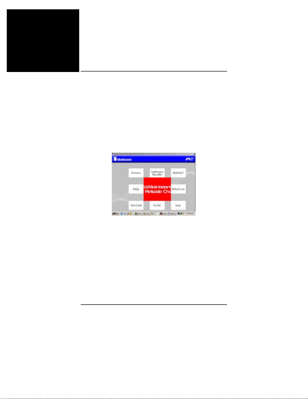
Configuration CMOS standard
Utilisez les touches fléchées pour sélectionner l'élément voulu et
utilisez les touches Pages préc. et Page suiv. pour sélectionner la valeur
voulue pour chaque élément.
Chargement des valeurs de sécurité (Fail-Safe) par défaut
Ce menu secondaire est utilisé pour diagnostiquer un problème apparu
au démarrage de l'ordinateur, si l'ordinateur ne démarre pas. Ces
réglages ne permettent pas d'avoir des performances optimales.
Installation des pilotes
Pilotes
Placez le premier CD utilitaires dans votre lecteur de CD. Le menu
principal s'affichera à l'écran. Sélectionnez l'élément Pilotes pour lancer
la fonction d'exécution automatique.
Aide
Cette option vous donne des informations concernant les fonctions et
les pilotes. Lisez attentivement car cela vous aidera pour l'installation.
Logiciels d'accompagnement
Cette option vous permet d'avoir des outils logiciels utiles qui vous
aideront à générer votre système informatique.
8
Page 73
Referencia rápida
Antes de comenzar
Esta referencia rápida junto con la guía EZ se usan para ofrecerle asistencia al
instalar el sistema en su ordenador. Para más información, lea el manual del
usuario.
1.
La electricidad estática puede causar daños a los
circuitos integrados de la placa base. Antes de
manipular la placa base fuera de su bolsa protectora,
asegúrese de que su cuerpo no esta cargado con
electricidad estática.
2.
Nunca ponga el procesador en funcionamiento sin
adjuntar firmemente el disipador. ¡PODRÍAN
OCURRIR DAÑOS PERM ANENTES!
Lista de Comprobación de Paquete
Si descubre que falta algún elemento o está dañado, póngase en contacto con su
distribuidor.
1. Placa Base 2. Cable de unidad de disco flexible
3. Cable IDE de 40 pin 4. Cable USB 5. Blindaje E/S 6. Cable SATA
(opcional) 7. Manual 8. Controladores 9. Cable1394 (opcional)
Español
1
Page 74
Español
Manual de la Placa Base
Instalación de hardware
CPU
1. Deslice la palanca hasta 90 grados.
2. Instale la CPU y asegúrese de que la
orientación del pin 1 está alineada con la esquina
más cercana a la punta de la palanca. No fuerce la
inserción de la CPU.
Aplique algo de material térmico en la parte
superior de la CPU e instale un ventilador con
disipador aprobado por el fabricante de la CPU.
Fije la CPU presionando la palanca hacia abajo y
bloqueándola.
3. Coloque el ventilador con el disipador en la
parte superior de la CPU y enganche los dos
ganchos de plástico en el módulo de retención
por los dos lados.
4. Presione la barra blanca en cada gancho para
asegurar el ventilador en el módulo de retención.
2
Page 75
Referencia rápida
Memoria
1. Localice las ranuras DIMM DDR en la placa base.
2. Installe los DIMM DDR en las ranura 1
usando ambas manos, después en la ranura 2, y
así continuamente.
3. Se cerrarán ambos extremos de la ranura para
sostener el DIMM DDR en su lugar cuando el
DIMM DDR llegue al fondo de la ranura.
Montaje de la Placa Base
1.
Si usa un destornillador eléctrico, debe ajustar la
fuerza en el rango de 5.0 ~ 8.0kg/cm.
2.
Tenga cuidado con los lados afilados de los
dispositivos.
1. Localice los agujeros de montaje en la placa
base.
Español
2. Coloque la placa en su lugar en la caja.
Asegúrese de que la placa y la caja están
alineadas.
3. fije la placa base con las barras de cobre.
3
Page 76
Español
Manual de la Placa Base
Conexión de los dispositivos
1. Localice los huecos de la unidad de disco flexible y
unidades de almacenamiento en la caja.
2. Coloque la unidad desde el lado del panel
frontal en el hueco.
3. Fije la unidad en el hueco con los tornillos.
4. Conente el cable de la unidad y los cables de alimentación. La linea
de color en el cable (señalada con una flecha azul) debe estar en el
mismo lado que el pin1 del conector.
Conexión de unidad de CD/DVD
1. Localice los huecos de la unidad de CD/DVD y unidades de
almacenamiento en la caja.
2. Coloque la unidad desde el lado del panel
frontal en el hueco.
3. Fije la unidad en el hueco con los tornillos.
4
Page 77
Referencia rápida
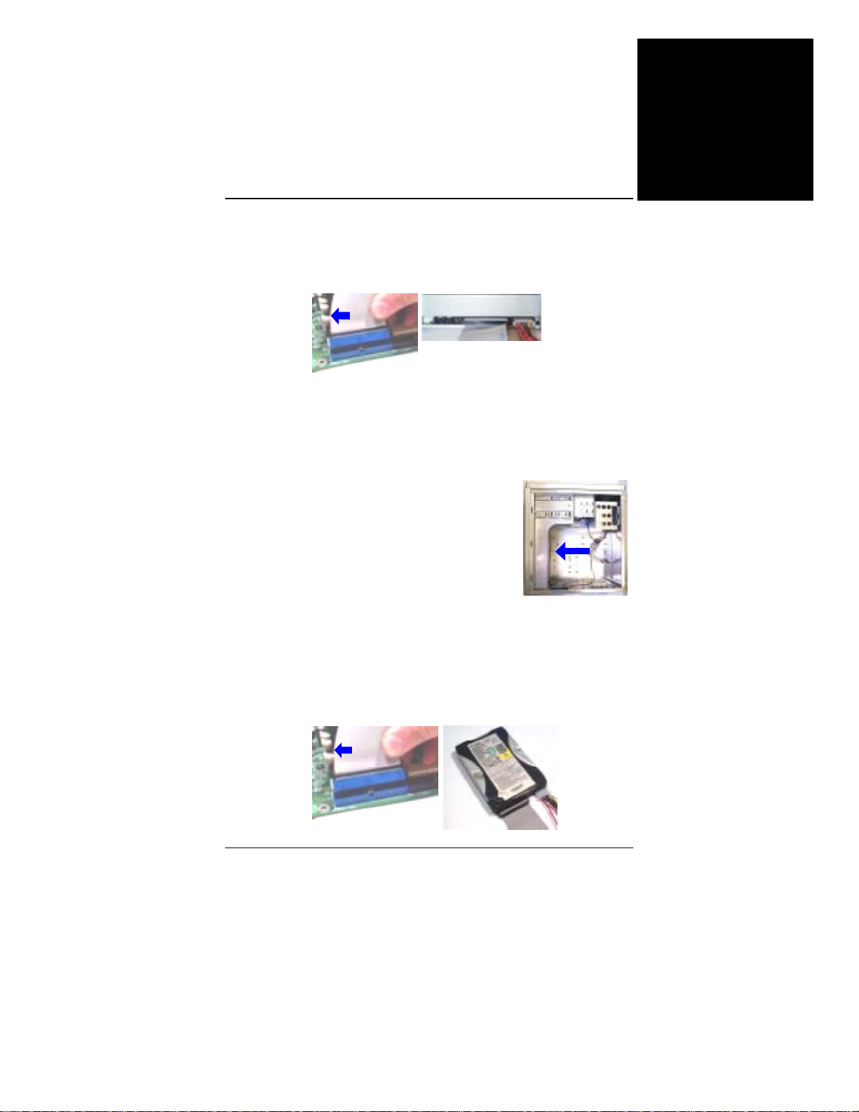
4. Conecte el cable IDE de la unidad y los cables de alimentación. La
linea de color en el cable (señalada con una flecha azul) debe estar en
el mismo lado que el pin1 del conector.
Conexión del Disco Duro
1. Localice los huecos de disco duro en la caja.
2. Coloque el disco duro desde la parte trasera
como indica la flecha.
Español
3. Fije la unidad en el hueco con los tornillos.
4. Conecte el cable IDE de la unidad y los cables de alimentación. La
linea de color en el cable (señalada con una flecha azul) debe estar en
el mismo lado que el pin1 del conector.
5
Page 78
Español
Manual de la Placa Base
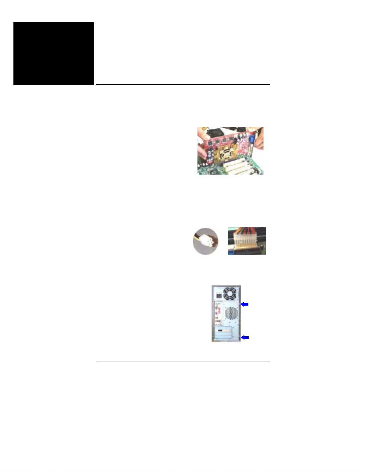
Instalación de Tarjetas
1. Seleccione una ranura de tarjeta disponible.
2. Quite la cubierta de la ranura del
chasis.
3. Presione la tarjeta firmemente en la ranura. Asegure la tarjeta con
el tornillo.
Conexión de la alimentación ATX
El conector de 20 agujeros se
conecta al conector de energía ATX.
El enchufe de 4 agujeros se conecta
al conector de energía ATX_12V.
Ensamblaje de la Caja del Sistema
Coloque la cubierta en la caja y
asegure los tornillos en la cubierta
(como muestran las flechas) con un
destornillador o con los dedos.
6
Page 79
Referencia rápida
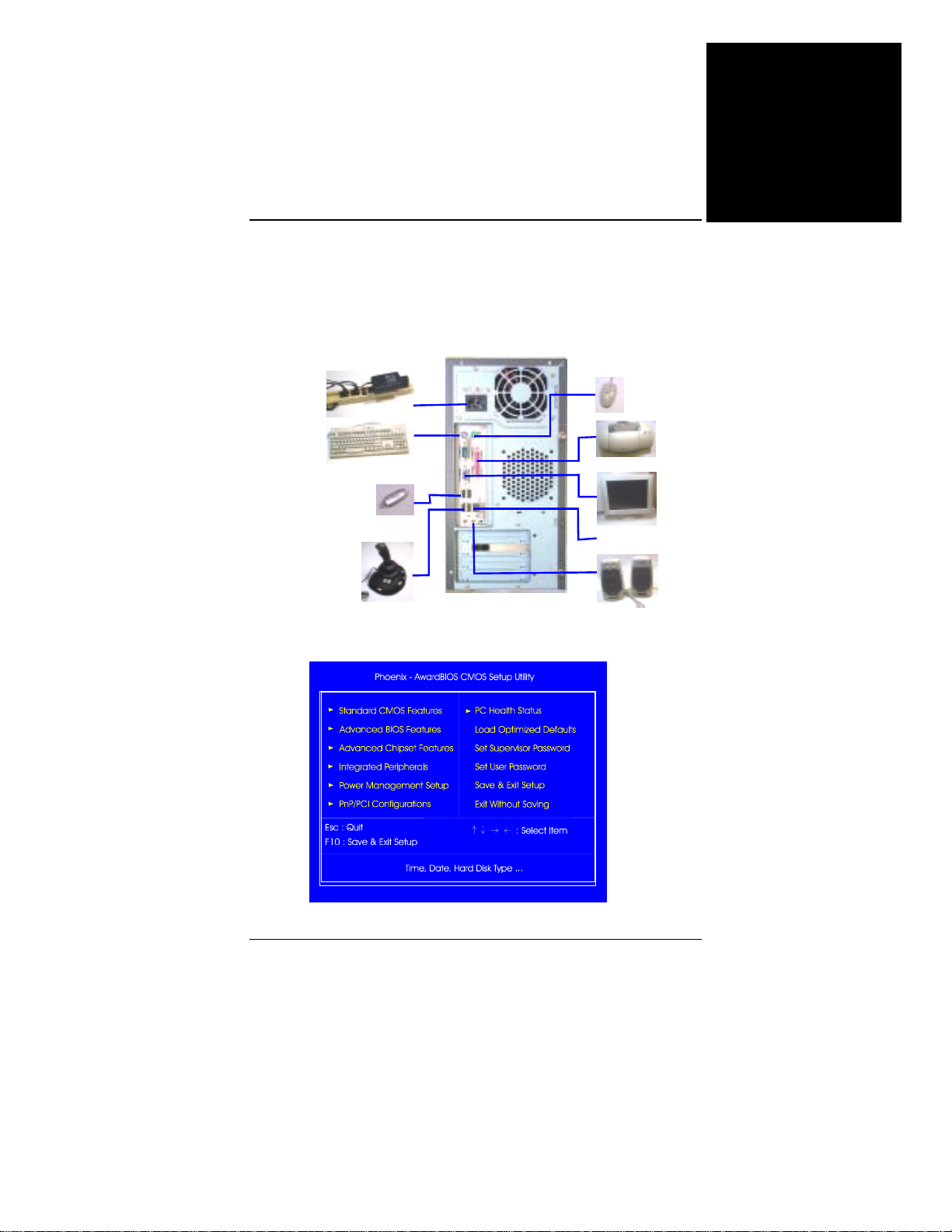
Conexión de Dispositivos Periféricos
Conecte los dispositivos periféricos al sistema por madio del panel
trasero/frontal.
Español
Cable de
alimentación del
sistema
Teclado PS/2
Módulo de Memoria
Flash USB
Joystick
Configuración BIOS
Ratón PS/2
Impresora
Monitor
Al conector LAN
Altavoz
7
Page 80
Español
Manual de la Placa Base
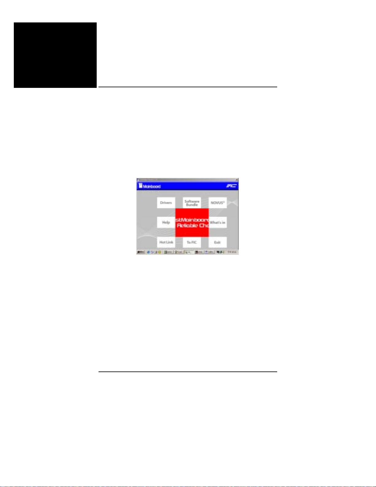
Configuración CMOS estándar
Use las teclas de cursor para resaltar el elemento y usar las teclas
AvPág y RePág para seleccionar el valor que desee para cada elemento.
Cargar opciones predeterminadas
Puede seleccionar este submenú para diagnosticar el problema después
de que inicie el ordenador, si el ordenador no ha iniciado correctamente.
Estas opciones no son necesariamente las óptimas.
Instalación de controladores
Controladores
coloque su CD de controladores en la unidad de CD. Aparecerá el
menú superior en la pantalla. Seleccione los Controladores para iniciar
la función de ejecución automática.
Ayuda
Le ofrece informaciónacerca de las funciones y controladores. Si la lee
encontrará ayuda para la instalación.
Paquete de software
Este elemento le ofrece algunas herramientas útiles para ayudarle a
administrar su sistema.
8
Page 81

快速參考指南
開始之前
本快速參考指南和 EZ 指南可以幫助您安裝電腦系統。有關的詳細資訊,
請閱讀用戶手冊。
1.
靜電可能會損壞主板上的積體電路。從保護袋中
取出主板進行操作時,應確保身上沒有靜電。
2.
在沒有正確牢固地安裝散熱片之前,切勿運行處
理器。否則,可能導致永久損壞!
包裝物品清單
如果下列任何物品損壞或缺失,請與經銷商聯繫。1. 主板 2. 軟碟驅動器
帶線 3. 80-針 IDE 帶線 4. USB 線 5. I/O 護蓋 6. SATA 線 (選購) 7.手冊 8. 驅
動程式 9. 1394 線 (選購)
繁體中文
1
Page 82
繁體中文
主機板手册
安裝硬體
CPU
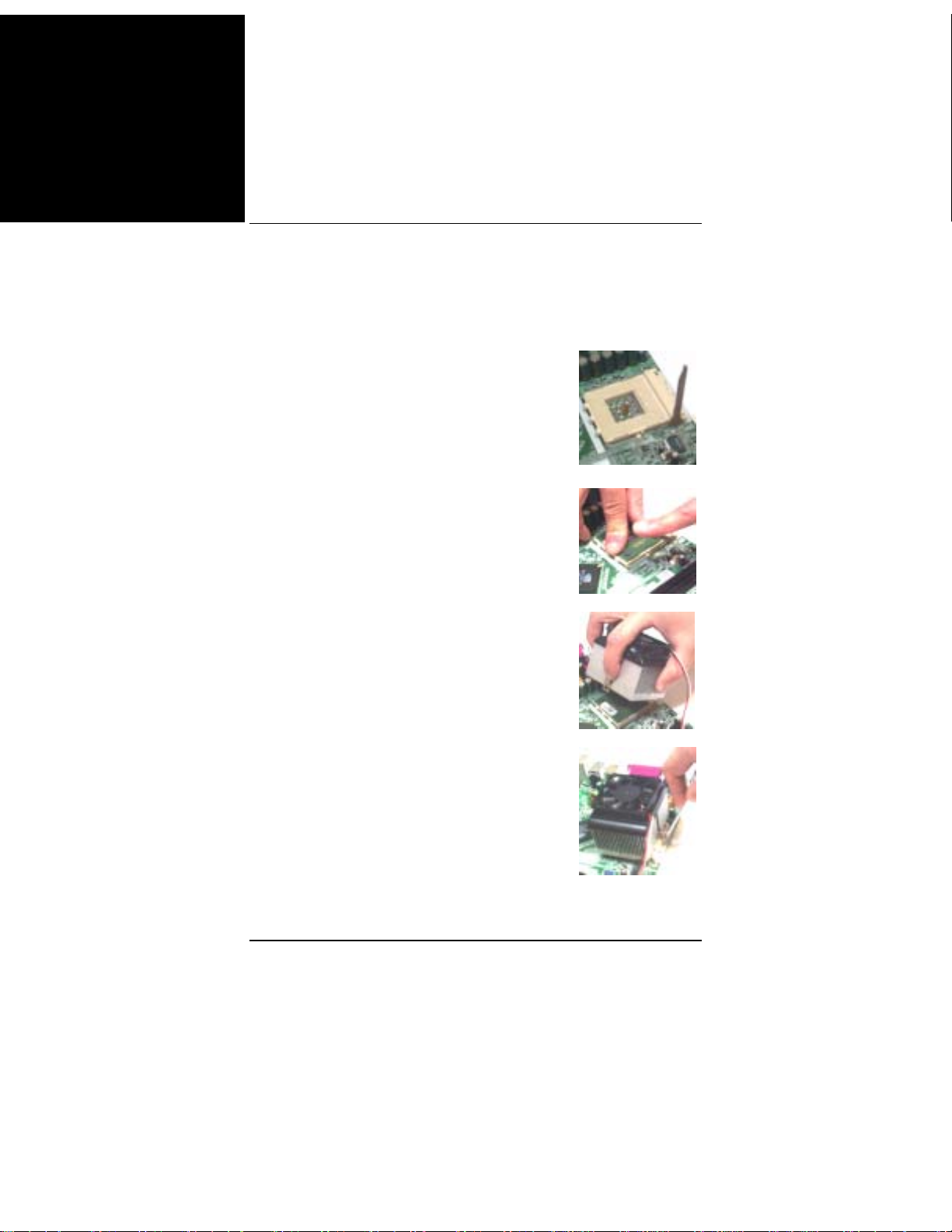
1. 將鎖杆向上擡起 90 度。
2. 安裝 CPU,將插座拐角標記對準距離鎖杆
頂端最近的插座拐角,確保管腳 1 的方向正
確。不要用力插入 CPU。
在 CPU 上面塗上一層熱物質;然後安裝經過
CPU 製造商認可的帶散熱片的風扇。向下按
鎖杆並鎖緊以固定 CPU。
3. 將帶散熱片的風扇放在 CPU 上面,然後
向下按兩個塑膠夾以鈎住支撐塊兩側的孔。
4. 向下按每個塑膠夾上的白色扳杆,將風扇
套件固定到支撐塊上。
2
Page 83
記憶體
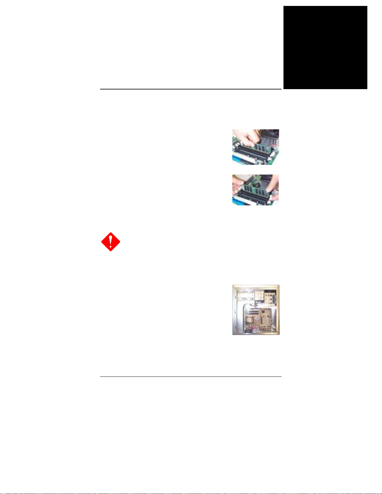
1. 在主板上找到 DDR DIMM 插槽。
2. 用雙手將第一條 DDR DIMM 垂直向下插入
插槽 1 中,第二條插入插槽 2 中,依次類
推。
3. 當 DDR DIMM 到達插槽底部後,插槽兩端
的卡子將鎖緊以使 DDR DIMM 安裝到位。
安裝主板
1.
當使用電動螺絲刀時,將轉矩設置在允許的範圍
內:5.0 ~ 8.0kg/cm。
2.
小心不要被設備的邊緣劃傷。
1. 在主板上找到安裝孔。
2. 將主板放在機箱內的托架上。務必對齊主
板和托架。
快速參考指南
繁體中文
3. 用銅的栓棒固定主板。
3
Page 84
繁體中文
主機板手册
連接設備
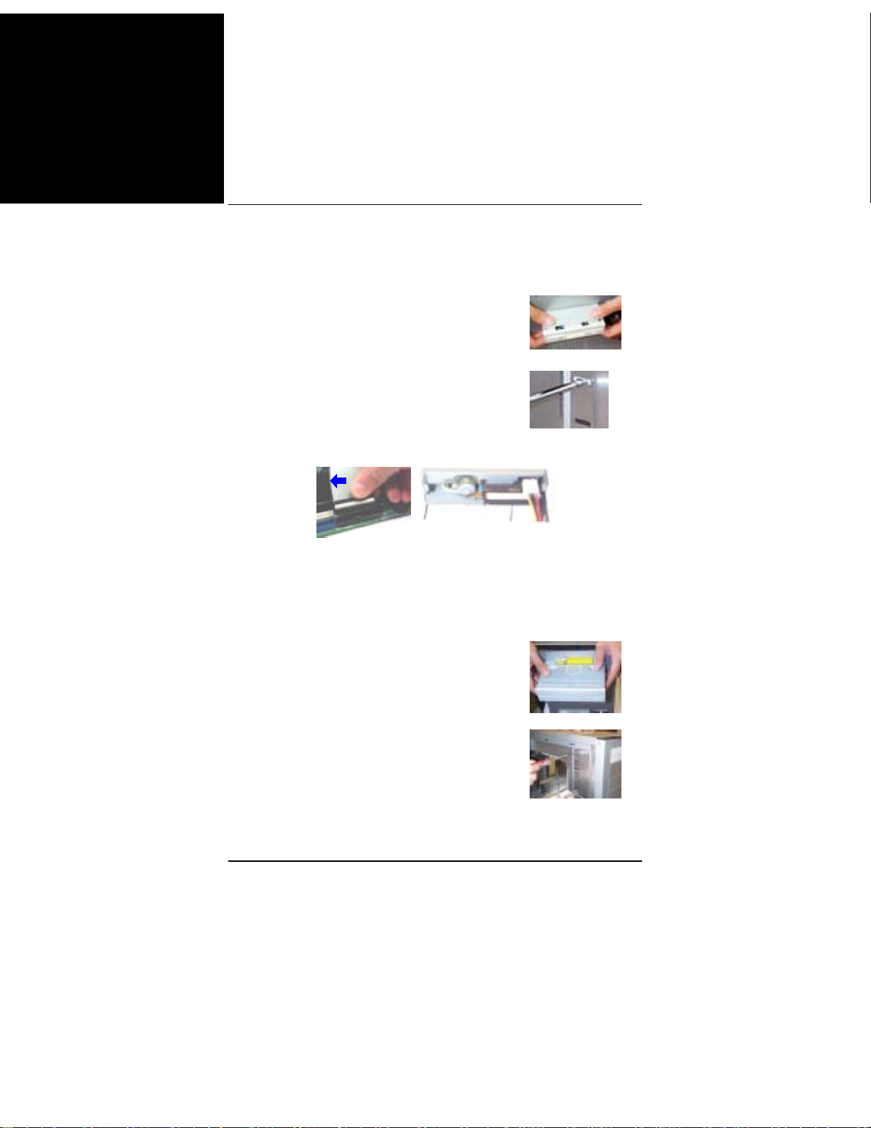
1. 在機箱上找到軟碟驅動器托架和存放位置。
2. 從前面板一側將驅動器推入託架中。
3. 用螺絲將驅動器固定在托架上。
4. 連接軟帶線和電源線。帶線上的彩色線(帶藍色箭頭)必須
與插口的管腳 1 位於同一側。
連接 CD/DVD 驅動器
1. 在機箱上找到 CD/DVD 驅動器托架和存放位置。
2. 從前面板一側將驅動器推入託架中。
3. 用螺絲將驅動器固定在托架上。
4
Page 85
快速參考指南
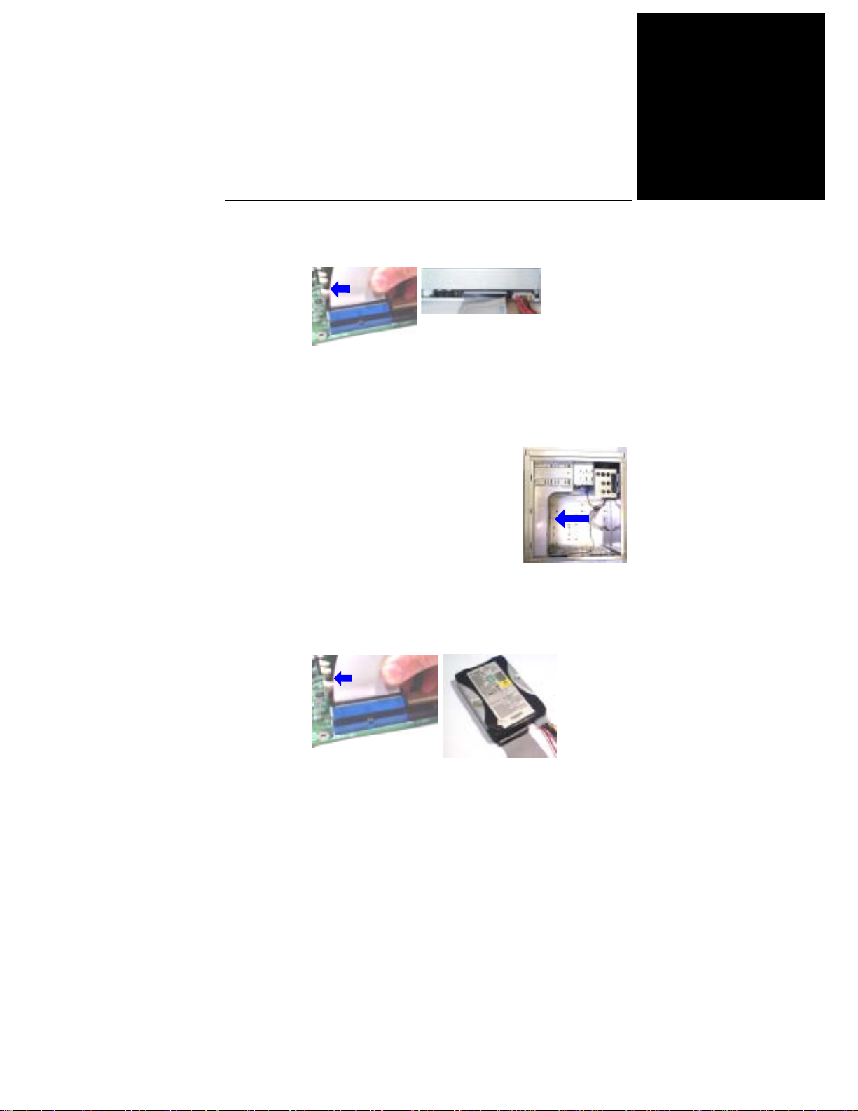
4. 連接 IDE 帶線和電源線。帶線上的彩色線(帶藍色箭頭)必
須與插口的管腳 1 位於同一側。
連接硬碟驅動器
1. 在機箱上找到硬碟驅動器托架和存放位置。
2. 將硬碟驅動器從托架後部裝入,如箭頭所
示。
繁體中文
3. 用螺絲將驅動器固定在托架上。
4. 連接 IDE 帶線和電源線。帶線上的彩色線(帶藍色箭頭)必
須與插口的管腳 1 位於同一側。
5
Page 86
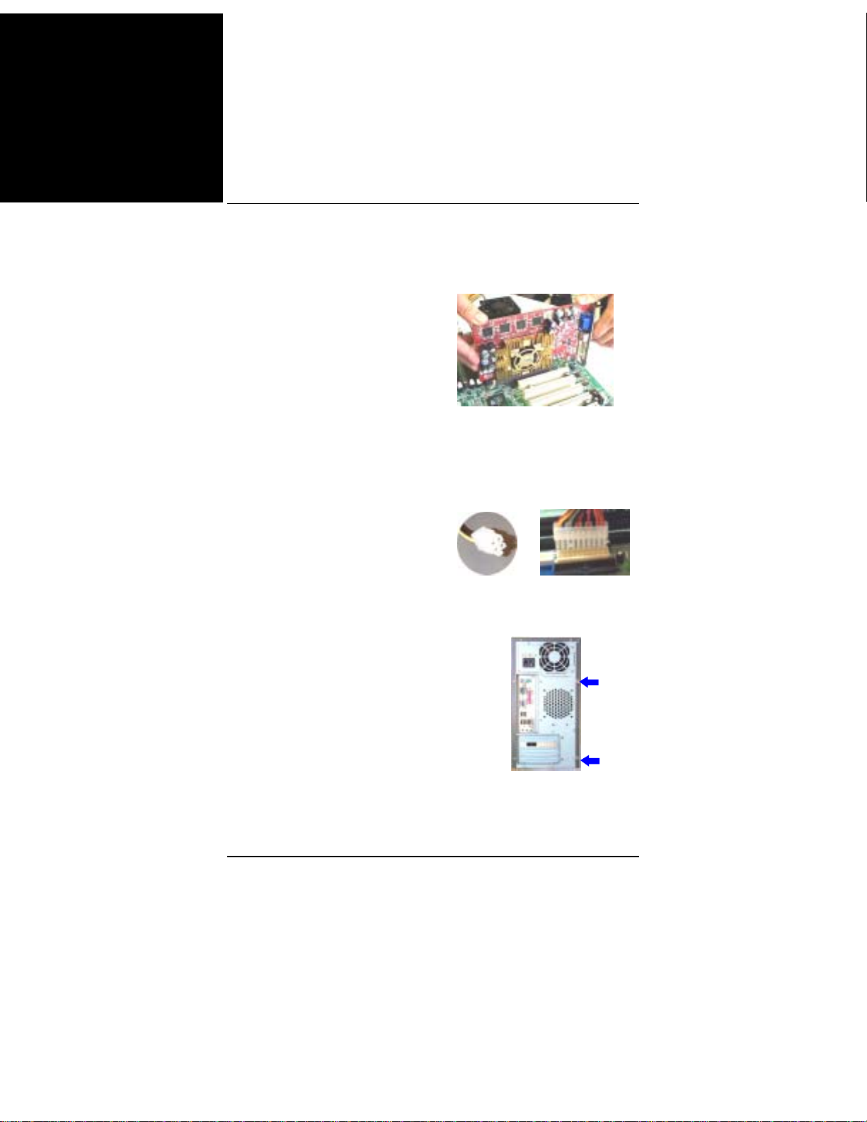
繁體中文
主機板手册
安裝卡
1. 選擇一個空閒的卡槽。
2. 從機箱上卸下槽蓋。
3. 將卡用力按入插槽中。用螺絲固定卡。
連接 ATX 電源
20-孔電源插頭連接到 ATX 電源插
口上。4- 孔電源插頭連接到
ATX_12V 電源插口上。
組裝系統機箱
裝上機箱蓋,然後用螺絲刀或手擰
緊蓋上的螺絲,如箭頭所示。
6
Page 87
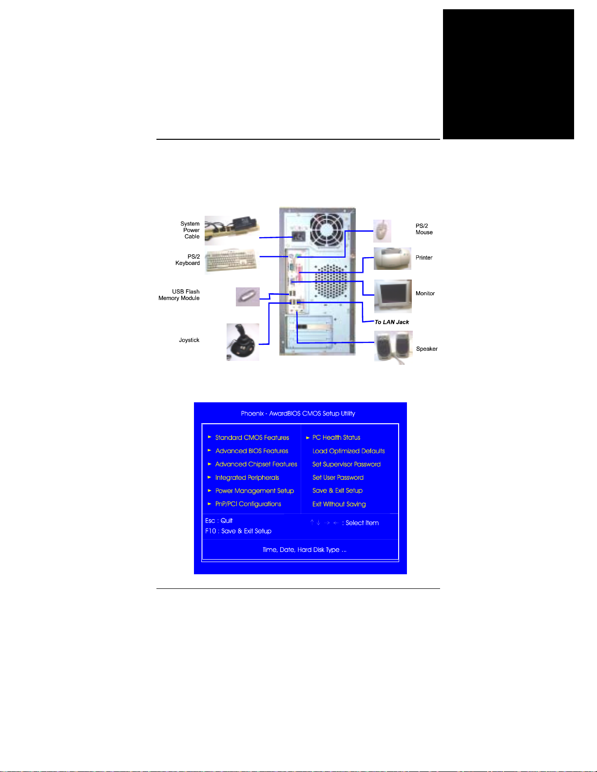
連接外設
通過前/後面板將外設連接到系統。
BIOS 設置
快速參考指南
繁體中文
7
Page 88
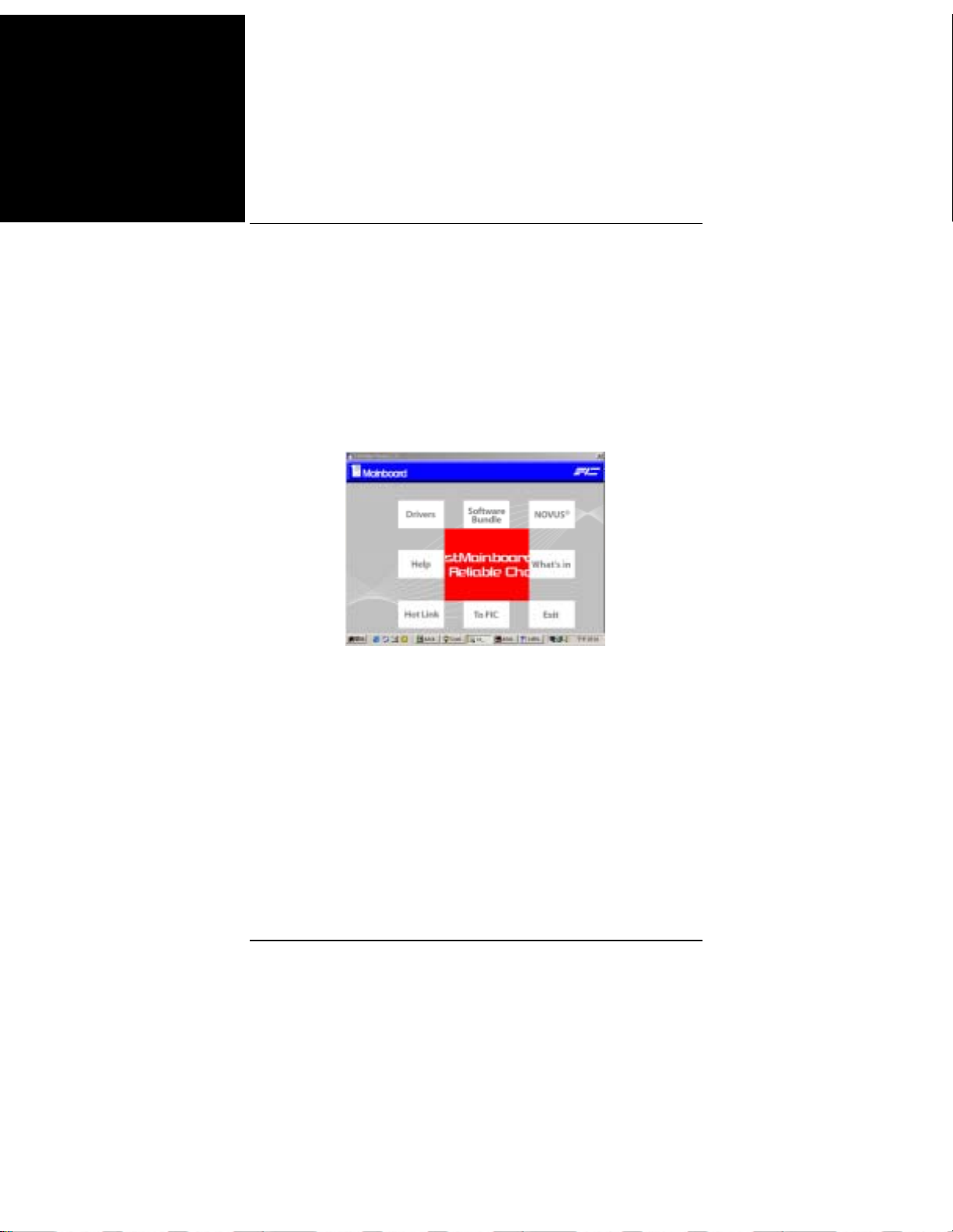
繁體中文
主機板手册
標準 CMOS 設置
使用箭頭鍵高亮顯示專案,然後使用 PgUp 或 PgDn 鍵爲每個專
案選擇合適的值。
載入故障保護預設值
當電腦不能引導時,可以選擇此子功能表在電腦引導後診斷故
障。這些設置不會提供最佳的性能。
安裝驅動程式
驅動程式
將第一張實用程式光碟插入光碟驅動器中。頂級功能表將顯示在
螢幕上。選擇專案“驅動程式”將啓動自動運行功能。
幫助
此專案提供與功能和驅動程式有關的一些資訊。閱讀這些資訊將
對安裝有所幫助。
附帶軟體
此專案提供一些有用的軟體工具以幫助您管理電腦系統。
8
Page 89
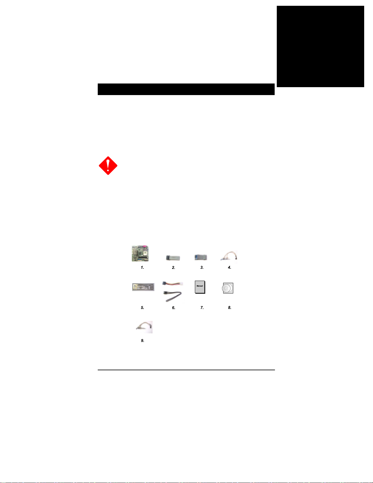
快速参考指南
开始之前
本快速参考指南和 EZ 指南可以帮助您安装计算机系统。有关的详细信
息,请阅读用户手册。
1.
2.
静电可能会损坏主板上的集成电路。从保护袋中
取出主板进行操作时,应确保身上没有静电。
在没有正确牢固地安装散热片之前,切勿运行处
理器。否则,可能导致永久损坏!
包装物品清单
如果下列任何物品损坏或缺失,请与经销商联系。
1. 主板 2. 软盘驱动器带线 3. 40-针 IDE 带线 4. USB 线 5. I/O 护盖 6. SATA
线 (选件) 7. 手册 8. 驱动程序 9. 1394 线 (选件)
简体中文
1
Page 90
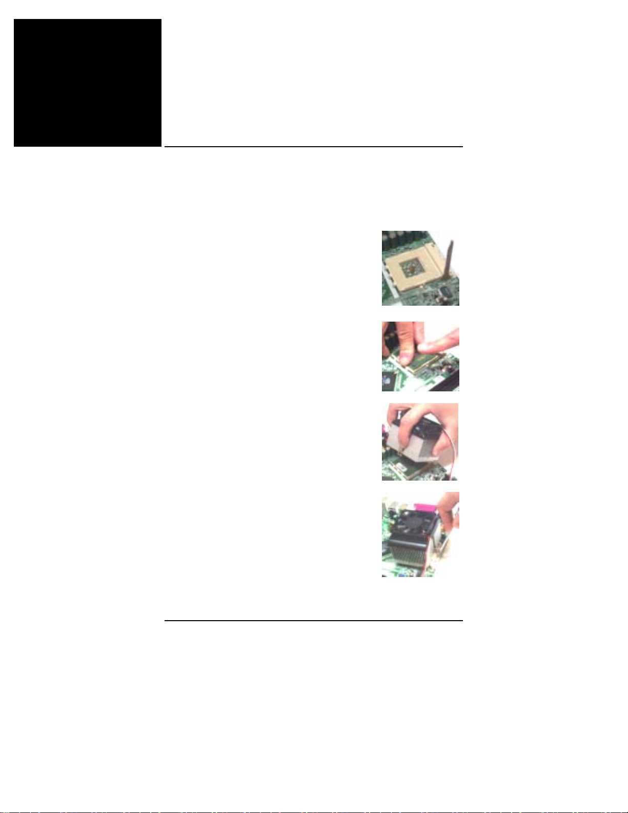
简体中文
主板手册
安装硬件
CPU
1. 将锁杆向上抬起 90 度。
2. 安装 CPU,将插座拐角标记对准距离锁杆
顶端最近的插座拐角,确保管脚 1 的方向正
确。不要用力插入 CPU。
在 CPU 上面涂上一层热物质;然后安装经过
CPU 制造商认可的带散热片的风扇。向下按
锁杆并锁紧以固定 CPU。
3. 将 带散热片的风扇放在 CPU 上面,然后
向下按两个塑料夹以钩住支撑块两侧的孔。
4. 向下按每个塑料夹上的白色扳杆,将风扇
套件固定到支撑块上。
2
Page 91
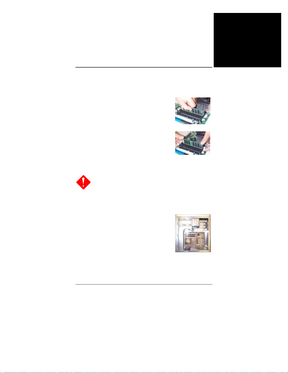
内存
1. 在主板上找到 DDR DIMM 插槽。
2. 用双手将第一条 DDR DIMM 垂直向下插入
插槽 1 中,第二条插入插槽 2 中,依次类
推。
3. 当 DDR DIMM 到 达插槽底部后,插槽两端
的卡子将锁紧以使 DDR DIMM 安装到位。
安装主板
1.
当使用电动螺丝刀时,将转矩设置在允许的范围
内:5.0 ~ 8.0kg/cm。
2.
小心不要被设备的边缘划伤。
1. 在主板上找到安装孔。
2. 将主板放在机箱内的托架上。务必对齐主
板和托架。
快速参考指南
简体中文
3. 用铜的栓棒固定主板。
3
Page 92
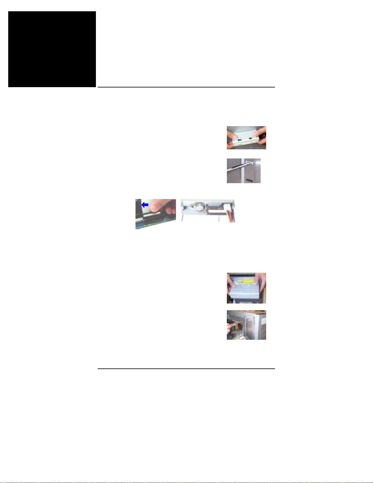
简体中文
主板手册
连接设备
1. 在机箱上找到软盘驱动器托架和存放位置。
2. 从前面板一侧将驱动器推入托架中。
3. 用螺丝将驱动器固定在托架上。
4. 连接软带线和电源线。带线上的彩色线(带蓝色箭头)必须
与插口的管脚 1 位于同一侧。
连接 CD/DVD 驱动器
1. 在机箱上找到 CD/DVD 驱动器托架和存放位置。
2. 从前面板一侧将驱动器推入托架中。
3. 用螺丝将驱动器固定在托架上。
4
Page 93
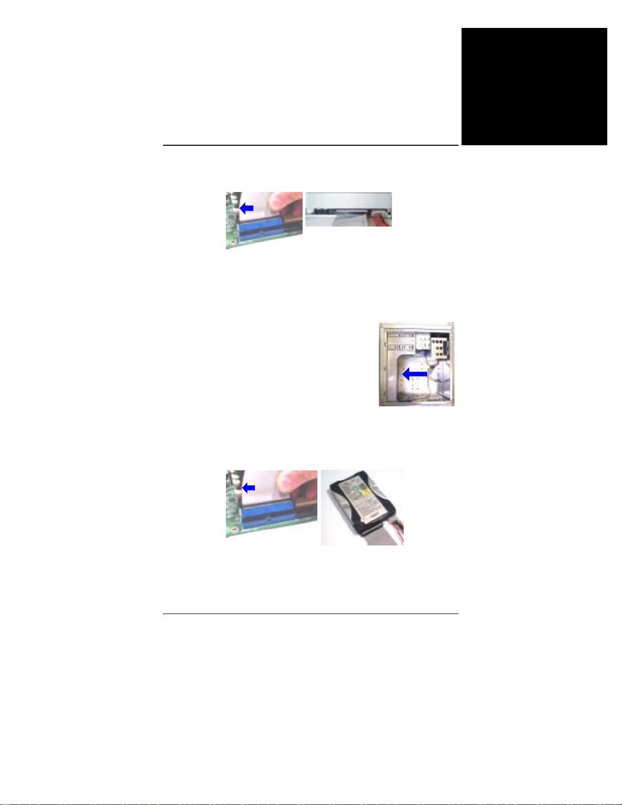
快速参考指南
4. 连接 IDE 带线和电源线。带线上的彩色线(带蓝色箭头)必
须与插口的管脚 1 位于同一侧。
连接硬盘驱动器
1. 在机箱上找到硬盘驱动器托架和存放位置。
2. 将硬盘驱动器从托架后部装入,如箭头所
示。
简体中文
3. 用螺丝将驱动器固定在托架上。
4. 连接 IDE 带线和电源线。带线上的彩色线(带蓝色箭头)必
须与插口的管脚 1 位于同一侧。
5
Page 94
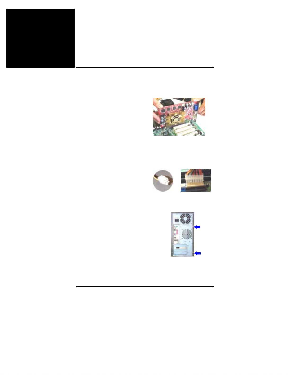
简体中文
主板手册
安装卡
1. 选择一个空闲的卡槽。
2. 从机箱上卸下槽盖。
3. 将卡用力按入插槽中。用螺丝固定卡。
连接 ATX 电源
20-孔电源插头连接到 ATX 电源插
口上。4- 孔电源插头连接到
ATX_12V 电源插口上。
组装系统机箱
装上机箱盖,然后用螺丝刀或手拧
紧盖上的螺丝,如箭头所示。
6
Page 95
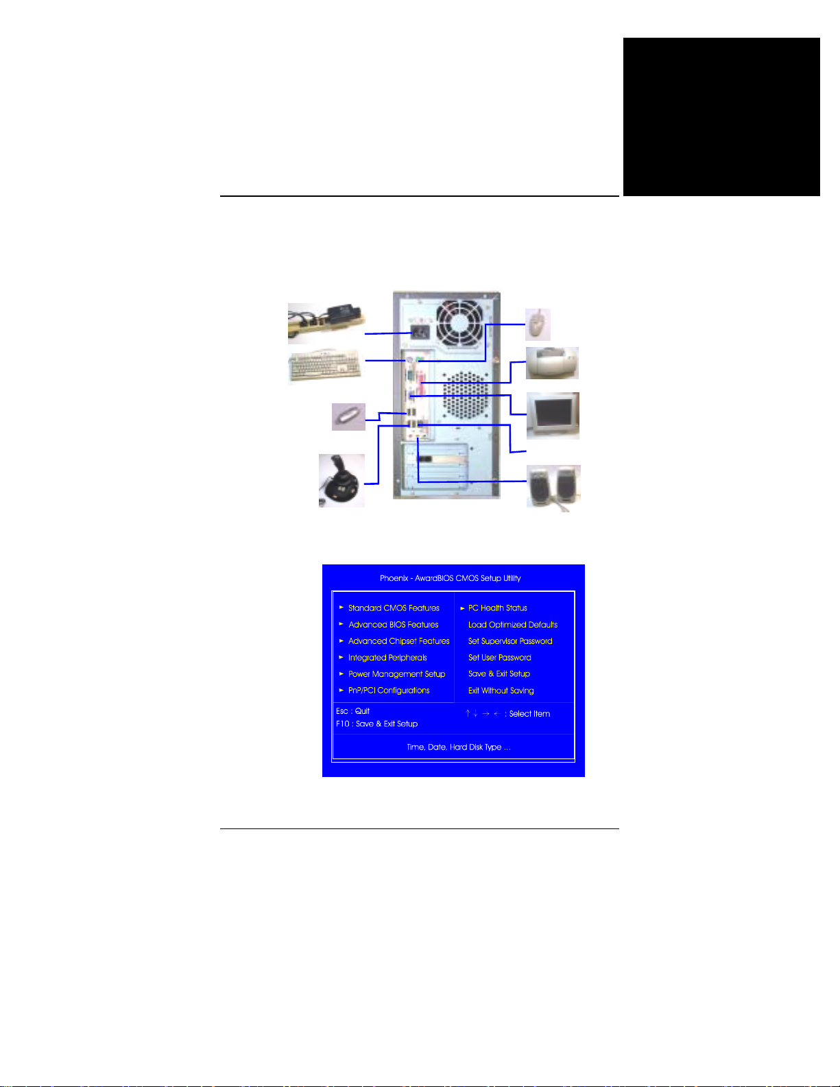
连接外设
通过前/后面板将外设连接到系统。
快速参考指南
简体中文
系统电源线
PS/2 键盘
USB 闪存模块
操纵杆
BIOS 设置
PS/2 鼠标
打印机
显示器
接 LAN 插口
音箱
7
Page 96
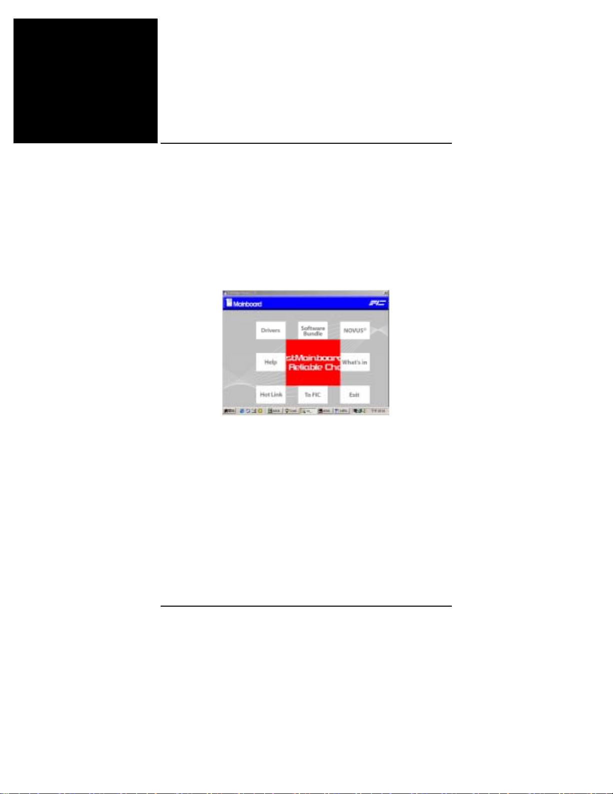
简体中文
主板手册
标准 CMOS 设置
使用箭头键高亮显示项目,然后使用 PgUp 或 PgDn 键为每个项
目选择合适的值。
加载故障保护默认值
当计算机不能引导时,可以选择此子菜单在计算机引导后诊断故
障。这些设置不会提供最佳的性能。
安装驱动程序
驱动程序
将第一张实用程序光盘插入光盘驱动器中。顶级菜单将显示在屏
幕上。选择项目“驱动程序”将启动自动运行功能。
帮助
此项目提供与功能和驱动程序有关的一些信息。阅读这些信息将
对安装有所帮助。
附带软件
此项目提供一些有用的软件工具以帮助您管理计算机系统。
8
 Loading...