

Page 1
www.hp.com/go/briosupport
Business PCs *
HP
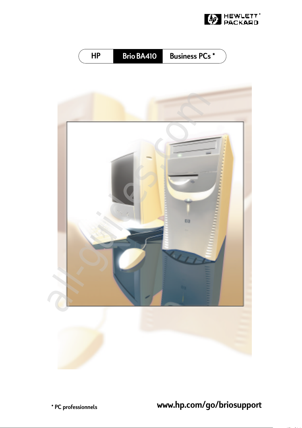
Brio BA410
* PC professionnels
All manuals and user guides at all-guides.com
all-guides.com
Page 2

All manuals and user guides at all-guides.com
Page 3
Table of Contents
HP Brio Guide
Setting Up Your HP Brio
UnpackingthePCandMonitor................ 2
ConnectingDevicestoYourHPBrioPC......... 3
ComfortandSafetyChecklist................. 6
Getting Started with Your HP Brio
StartingYourHPBrio...................... 10
SettingUpWindows....................... 10
WakingYourHPBriofromaSleepState ....... 11
StoppingYourHPBrio..................... 11
YourPC’sDesktop........................ 12
HPBrioCenter-YourDesktopAssistant ........ 13
UsingYourSoftware ...................... 16
FindingInformationontheWeb .............. 16
SecuringYourHPBrio ..................... 16
If You Have a Problem
WhattoDoFirst.......................... 18
MyHPBrioDoesn’tStartProperly............ 19
MyHPBrioIsn’tWorkingProperly............ 21
WhatKindofProblemIsIt?................. 22
All manuals and user guides at all-guides.com
Page 4
ii
HardwareProblems....................... 23
SoftwareProblems ....................... 31
MyHPBrioHasanAudio(Sound)Problem...... 33
MyHPBrioDetectsanErroratStartup........ 35
FrequentlyAskedQuestions................. 41
NeedMoreHelp?......................... 41
HPHardwareDiagnostics(e-DiagTools)........ 42
HPBrioAssistCD-ROM.................... 43
SupportandInformationServices............. 45
Upgrading and Replacing HP Brio Hardware
Important-BeforeYouStart ................ 48
InsidetheComputer....................... 48
AccessingInternalComponents.............. 49
ReplacingtheSystemBoard................. 55
CablesandConnectorsinYourPC............ 57
ReplacingaProcessor ..................... 58
ReplacingtheFloppyDrive.................. 59
ReplacingtheHardDrive ................... 60
InstallinganExpansionBayDrive............. 62
InstallingaMemoryModule................. 65
InstallinganExpansionCard................. 66
ReplacingthePowerSupplyUnit............. 67
ReplacingtheBattery...................... 69
All manuals and user guides at all-guides.com
Page 5
iii
Part Number 5970-5010-EN
Printed 05/00 in
Paper not bleached with chlorine
Technical Information
HPSetupProgram........................ 72
Clearing Your PC’s CMOS (BIOS) Settings . . . . . . 74
YourPC’sBIOS .......................... 76
TechnicalCharacteristics................... 77
Regulatory, Warranty and Support
RegulatoryInformation..................... 80
RecyclingyourPC ........................ 85
HPHardwareWarranty .................... 86
HPSoftwareLimitedWarranty............... 94
HPSoftwareLicenseAgreement ............. 95
InternationalWarranty..................... 97
HP Year 2000 Warranty . . . ................. 97
HP Customer Care Center Phone Numbers . . . . . . 98
OtherServices........................... 99
All manuals and user guides at all-guides.com
Page 6
iv
Important Safety Information
For your safety, never remove the PC’s cover without first removing the power
cord and any connection to a telecommunications network. Always replace the
cover before switching the PC on again.
For your safety, always connect equipment to a grounded electrical wall outlet.
Always use a power cord with a properly grounded plug, such as the one provided
with the equipment, or one in compliance with your national safety standards. The
equipment can be disconnected from the power by removing the power cord from
the power outlet. This means the equipment must be located close to an easily
accessible electrical outlet.
To avoid electrical shock, do not open the power supply. There are no user-
serviceable parts inside.
There is a danger of explosion if the battery is incorrectly installed. For your
safety, never attempt to recharge, disassemble or burn an old battery. Only replace
the battery with the same or equivalent type, as recommended by the
manufacturer. The battery in this PC is a lithium battery that does not contain any
heavy metals. Nevertheless, in order to protect the environment, do not dispose of
batteries in household waste. Please return used batteries either to the shop from
which you bought them, or to the dealer from whom you purchased your PC, or to
HP, so that they can either be recycled or disposed of in the correct way. Returned
used batteries will be accepted free of charge.
Do not attempt to connect this product to the phone line during a lightning storm.
Never install telephone jacks in wet locations unless the telephone line has been
disconnected at the network interface. Never touch uninsulated telephone wires
or terminals unless the telephone line has been disconnected at the network
interface. Use caution when installing or modifying telephone lines. Avoid using a
telephone (other than a cordless type) during a lightning storm. There may be a
risk from lightning. Do not use the telephone to report a gas leak in the vicinity of
the leak. Never touch or remove the communications board without first removing
the connection to the telephone network.
Use minimum Nº 26 AWG wire for telephone cable.
Choosing a Comfortable Workspace
Choose a workspace for your computer near a grounded electrical wall
socket. If your monitor has a tilt-swivel base, attach it to the monitor as
described in the monitor manual. Position the monitor on your desk.
Position the computer to allow proper ventilation and access to the cables.
WARNING
If you are in doubt that you can lift the equipment safely, do not try to move it without
help.
All manuals and user guides at all-guides.com
all-guides.com
Page 7
v
HP Brio Information Roadmap
HP Brio Guide
The HP Brio Guide (this manual) will help you:
•
Set up and begin using your HP Brio PC for the first time
• Troubleshoot your PC
• Upgrade and replace components in your PC
• Find out where to get more information.
Your PC’s Online HP Brio Center
HP Brio Center
- for information on:
• Using your PC
• Using Windows
• Fixing problems with your PC.
Refer to “HP Brio Center-Your Desktop Assistant” on page 13 for more
information.
Information on the HP Brio Support Web Site
Refer to the HP Brio support web site (
www.hp.com/go/briosupport
)
for a wide range of information, including:
• Downloadable documentation
•
Service and support options
• The latest versions of drivers and utilities
•
BIOS updates
• Answers to Frequently Asked Questions.
HP Brio Assist CD-ROMs
Used for a full system recovery or alternative OS installation. Includes
instructions on how to recover your preloaded software including
operating system, drivers and utilities.
All manuals and user guides at all-guides.com
Page 8
vi
Notice
The information contained in this document is subject to change without
notice.
Hewlett-Packard makes no warranty of any kind with regard to this
material, including, but not limited to, the implied warranties of
merchantability and fitness for a particular purpose. Hewlett-Packard
shall not be liable for errors contained herein or for incidental or
consequential damages in connection with the furnishing, performance, or
use of this material.
This document contains proprietary information that is protected by
copyright. All rights are reserved. No part of this document may be
photocopied, reproduced, or translated to another language without the
prior written consent of Hewlett-Packard Company.
Adobe and Acrobat are trademarks of Adobe Systems Incorporated.
Microsoft, MS-DOS, Windows and Windows NT are U.S registered
trademarks of Microsoft Corporation.
Hewlett-Packard France
Business Desktop Division
38053 Grenoble Cedex 9
France
© 2000 Hewlett-Packard Company
Important Ergonomic Information
Improper and prolonged use of keyboards and input devices are among those tasks associated
with repetitive strain injury (RSI) to soft tissues in the hands and arms. If you do experience
discomfort or pains while using any computing equipment, discontinue use immediately and
consult your physician as soon as possible.
Your comfort and safety are our primary concern. Consequently, we strongly recommend that
you read HP’s ergonomic information before using your PC. For detailed information, refer to
HP’s online version of “Working in Comfort” which is preloaded on your PC’s hard disk or visit
HP’sWorkinginComfortWebsiteat:www.hp.com/ergo/.Asummaryisprovidedinthe
Comfort and Safety Checklist on page 6.
All manuals and user guides at all-guides.com
Page 9
1
Status
Setting Up Your HP Brio
This chapter describes how to set up your HP Brio PC.
Unpacking the PC and Monitor....................................................... page 2
Connecting Devices to Your HP Brio PC ......................................... page 3
Comfort and Safety Checklist........................................................ page 6
All manuals and user guides at all-guides.com
Page 10
Unpacking the PC and Monitor
2
Unpacking the PC and Monitor
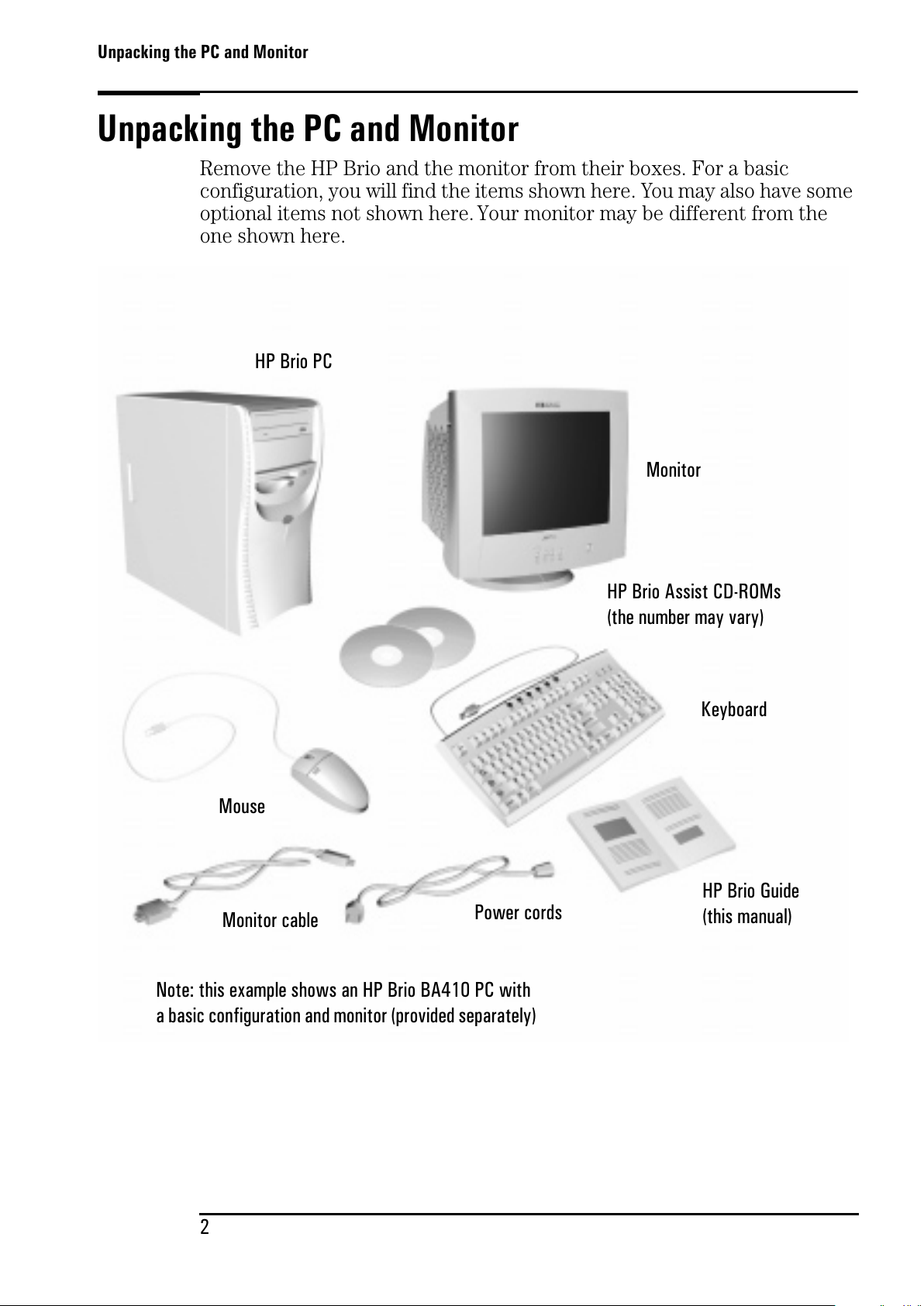
Remove the HP Brio and the monitor from their boxes. For a basic
configuration, you will find the items shown here. You may also have some
optional items not shown here. Your monitor may be different from the
one shown here.
Monitor
Monitor cable
Power cords
HP Brio Guide
(this manual)
Mouse
Keyboard
HP Brio Assist CD-ROMs
(the number may vary)
HP Brio PC
Note: this example shows an HP Brio BA410 PC with
a basic configuration and monitor (provided separately)
All manuals and user guides at all-guides.com
Page 11
Connecting Devices to Your HP Brio PC
3
Connecting Devices to Your HP Brio PC
Caution
Check that the correct power supply voltage is selected for your country (the voltage is set
during manufacturing and should already be correct).
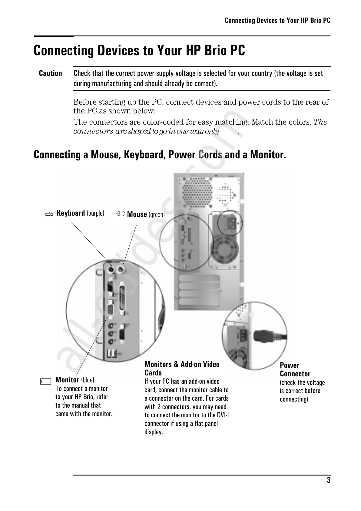
Before starting up the PC, connect devices and power cords to the rear of
the PC as shown below:
The connectors are color-coded for easy matching. Match the colors. The
conne ct or s a re shaped to go in one way only .
Connecting a Mouse, Keyboard, Power Cords and a Monitor.
Mouse
(green)
Keyboard
(purple)
Monitor
(
blue
)
To connect a monitor
to your HP Brio, refer
to the manual that
came with the monitor.
Power
Connector
(check the voltage
is correct before
connecting)
Monitors & Add-on Video
Cards
If your PC has an add-on video
card, connect the monitor cable to
a connector on the card. For cards
with 2 connectors, you may need
to connect the monitor to the DVI-I
connector if using a flat panel
display.
All manuals and user guides at all-guides.com
all-guides.com
Page 12
Connecting Devices to Your HP Brio PC
4
Connecting Other Equipment
WARNING Always turn the volume down before connecting headphones or speakers to avoid
discomfort from unexpected noise or static. Listening to loud sounds for prolonged
periods of time may permanently damage your hearing. Before putting on headphones,
place them around your neck and turn the volume down. When you put the headphones
on, slowly increase the volume until you find a comfortable listening level. When you
are able to hear comfortably and clearly, without distortion, leave the volume in that
position.
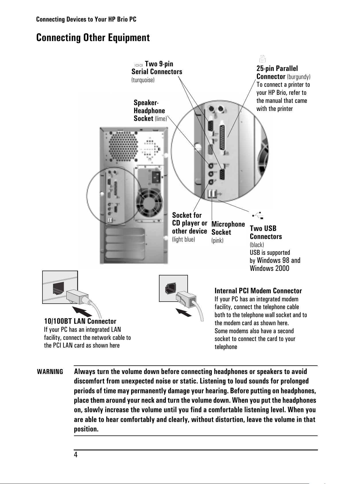
25-pin Parallel
Connector
(burgundy)
To connect a printer to
your HP Brio, refer to
the manual that came
with the printer
Two USB
Connectors
(black)
USB is supported
by
Windows 98 and
Windows 2000
Two 9-pin
Serial Connectors
(turquoise)
Socket for
CD player or
other device
(light blue)
Speaker-
Headphone
Socket
(lime)
Microphone
Socket
(pink)
10/100BT LAN Connector
If your PC has an integrated LAN
facility, connect the network cable to
the PCI LAN card as shown here
Internal PCI Modem Connector
If your PC has an integrated modem
facility, connect the telephone cable
both to the telephone wall socket and to
the modem card as shown here.
Some modems also have a second
socket to connect the card to your
telephone
All manuals and user guides at all-guides.com
Page 13
Connecting Devices to Your HP Brio PC
5
Setting the Country for Your Modem
You must ensure the country setting for your modem is correct. The
country is set to match the country you select when configuring your
operating system. In some cases, however, the modem may not correctly
identify a corresponding country profile. In such cases, reselection may be
required to match your exact location.
Checking Settings for the 56K V90 External USB Modem
To check the current settings:
1 From the Windows taskbar, click
Start
Settings
Control Panel
.
2 Double-click on the
Modem Country Select
icon.
3 Change the country setting if necessary.
Checking Settings for the 56K V90 Internal PCI Modem
To check the current settings:
For Windows 98 Users
1 Right-click on the
My Computer
icon and select
Properties
.
2 Select the
Device Manager
tab and double-click on
Modem
.
3 Select the modem model and click on
Properties
.
4 Click the
Country Select
tab. The current country setting is marked by an
asterisk. Change the country setting if necessary.
For Windows 2000 and Windows NT 4.0 Users
The modem country settings are configured automatically depending on
the country setting chosen for your operating system.
All manuals and user guides at all-guides.com
Page 14
Comfort and Safety Checklist
6
Comfort and Safety Checklist
Before using your new HP Brio PC, ensure that your working environment
is correct.
Preparing Your Work Environment
When using HP computing equipment, it is important that your work
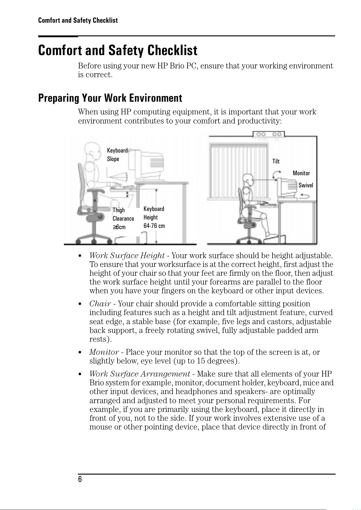
environment contributes to your comfort and productivity:
•
Work Surface Height - Your work surface should be height adjustable.
To ensure that your worksurface is at the correct height, first adjust the
height of your chair so that your feet are firmly on the floor, then adjust
the work surface height until your forearms are parallel to the floor
when you have your fingers on the keyboard or other input devices.
•
Chair - Your chair should provide a comfortable sitting position
including features such as a height and tilt adjustment feature, curved
seat edge, a stable base (for example, five legs and castors, adjustable
back support, a freely rotating swivel, fully adjustable padded arm
rests).
• Monitor - Place your monitor so that the top of the screen is at, or
slightly below, eye level (up to 15 degrees).
•
Work Surface Arrangement - Make sure that all elements of your HP
Brio system for example, monitor, document holder, keyboard, mice and
other input devices, and headphones and speakers- are optimally
arranged and adjusted to meet your personal requirements. For
example, if you are primarily using the keyboard, place it directly in
front of you, not to the side. If your work involves extensive use of a
mouse or other pointing device, place that device directly in front of
Keyboard
Slope
Keyboard
Height
64-76 cm
Thigh
Clearance
≥6cm
Swivel
Monitor
Tilt
All manuals and user guides at all-guides.com
Page 15
Comfort and Safety Checklist
7
your left or right arm. If you are using both a mouse and keyboard, place
them both at the same work surface height and close together. If a palm
rest is used, the height should be flush with the front edge of the
keyboard. Other items, such as your telephone or notepad, should also
be considered.
Caution Various aspects of using mice, keyboards and other input devices may increase your risk of
discomfort or injury. Optimize your comfort and safety by positioning these devices properly.
Your Work Posture
Sitting in one position for long periods can be uncomfortable. To minimize
the potential risk for physical discomfort or injury, it’s important that you
maintain a proper posture.
• Head - When viewing your monitor, your head should not be tilted more
than 15 degrees forward, and do not turn your head toward either side.
•
Back - While sitting at your work surface, make sure your back is
supported by the chair's backrest in an erect position or angled slightly
backwards.
• Arms - Make sure your arms and elbows are relaxed and loose, with
your upper arms perpendicular to the floor or tilted downward not more
than 15 degrees. Keep your forearms and hands approximately parallel
with the floor with elbows bent between 70 and 115 degrees. Keep your
elbows close to your sides (less than 20 degrees away from your body).
•
Hands, Wrists, Forearms - Try to keep your hands wrists and forearms
in a relaxed neutral position when using your mouse keyboard or other
input devices. For example, while using your keyboard and mouse, rest
your forearms (flat) on your desktop.
• Legs - Your thighs should be horizontal or angled slightly downward.
Your lower legs should be near a right angle to your thighs. Make sure
there is sufficient room under the work surface for your legs.
•
Feet - If after adjusting your chair you cannot rest your feet comfortably
on the floor, use a footrest, preferably one that can be adjusted in height
and angle.
Overall
•
Look away from the screen from time-to-time to help reduce eyestrain.
Focus on distant objects briefly, and blink periodically to lubricate your
eyes. You also should have your eyes checked on a regular basis and
ensure your eyeglass prescription is suitable for working on a computer
monitor.
All manuals and user guides at all-guides.com
Page 16
Comfort and Safety Checklist
8
• Remember to occasionally shift position and move your body. Keeping
your body in one position for long periods is unnatural and stressful.
When prolonged work is required, take frequent short breaks. As a rule
of thumb, a five or ten minute break every hour is a good idea. Short
frequent breaks are more beneficial than longer less frequent breaks.
Data show that people who work for long periods of time without a
break may be more prone to ergonomic injury.
• Changing tasks frequently will help prevent muscle stiffness. Examples:
alternating between keyboarding, reading, writing, filing, and moving
around in your work environment, helps you maintain a relaxed
posture. Occasionally stretch the muscles in your hands, arms,
shoulders, neck and back. You should stretch at least as often as you
take brief task breaks—at least once every hour.
• Discomfort may be alleviated by using alternative ergonomic designs
and accessories such as ergonomically personalized chairs, palm rests,
keyboard trays, alternative input devices, prescription eyeglasses, anti-
glare screens, and more. Seek additional information from the sources
available to you, including your employer, doctor, local office supply
store, and the Information Sources listed in the online version of
Working in Comfort, preloaded on the hard disk of your HP computing
equipment or available on the HP web site: www.hp.com/ergo.
All manuals and user guides at all-guides.com
all-guides.com
Page 17
2
Status
Getting Started with Your HP Brio
This chapter describes how to begin working with your HP Brio PC and
how to use the online HP Brio Center preinstalled on your PC.
Starting Your HP Brio .................................................................... page 10
Setting Up Windows...................................................................... page 10
Stopping Your HP Brio ................................................................... page 11
Your PC’s Desktop......................................................................... page 12
HP Brio Center-Your Desktop Assistant ......................................... page 13
Using Your Software ..................................................................... page 16
Finding Information on the Web ..................................................... page 16
Securing Your HP Brio ................................................................... page 16
All manuals and user guides at all-guides.com
Page 18
Starting Your HP Brio
10
Starting Your HP Brio
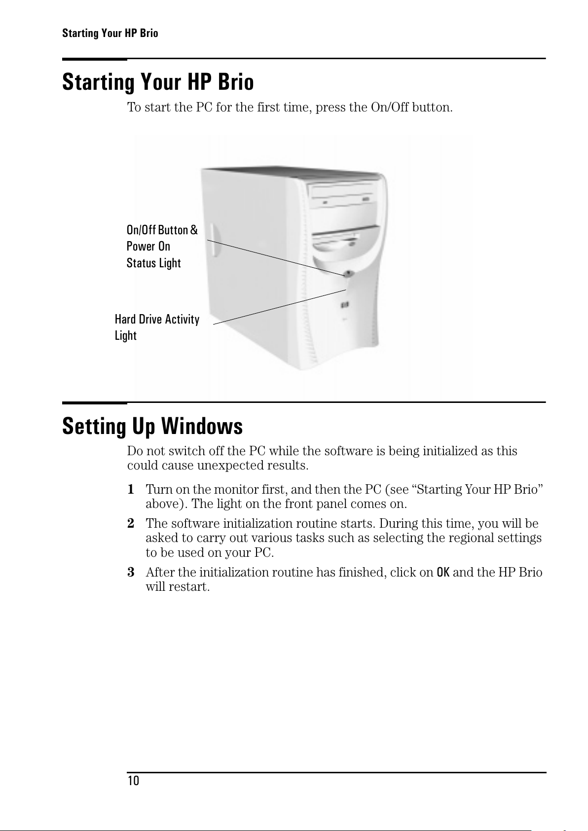
To start the PC for the first time, press the On/Off button.
Setting Up Windows
Do not switch off the PC while the software is being initialized as this
could cause unexpected results.
1 Turn on the monitor first, and then the PC (see “Starting Your HP Brio”
above). The light on the front panel comes on.
2 The software initialization routine starts. During this time, you will be
asked to carry out various tasks such as selecting the regional settings
to be used on your PC.
3 After the initialization routine has finished, click on OK and the HP Brio
will restart.
On/Off Button&
Power On
Status Light
Hard Drive Activity
Light
All manuals and user guides at all-guides.com
Page 19
Waking Your HP Brio from a Sleep State
11
Waking Your HP Brio from a Sleep State
After a period of inactivity, your HP Brio can go into one of a series of
sleep states. These are indicated by blinking of the power-on status light
on the HP Brio’s front panel. To wake the PC, try hitting a key on your
keyboard or, if this does not work, press the On/Off button. The PC can
only be woken in this way when it is in the deepest sleep state.
Stopping Your HP Brio
To stop the PC, exit all applications and then use your operating system’s
Shut Down commandintheStart menu (for Windows 98, Windows
2000 and Windows NT 4.0).
Note
If you want to force your PC to shut down, for example, if your operating system does not
respond, press and hold the power button for approximately 5 seconds.
All manuals and user guides at all-guides.com
Page 20
Your PC’s Desktop
12
Your PC’s Desktop
Note
All the features described in this section are standard to Windows. For further details on any
of these features, together with details on general Windows functionality, refer to the relevant
Windows documentation or to Windows Help.
You can find out more about your Windows desktop by following the
Windows Tour (click on
UsingYourHPBrioPC-WindowsTour
in the HP Brio
Center) or by referring to the Windows documentation supplied with your
computer.
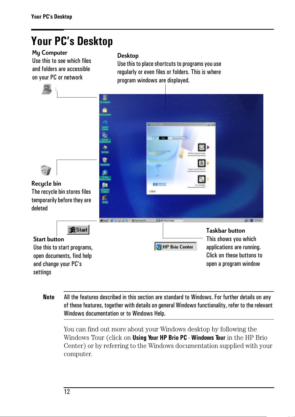
Start button
Use this to start programs,
open documents, find help
and change your PC’s
settings
Taskbar button
This shows you which
applications are running.
Click on these buttons to
open a program window
My Computer
Use this to see which files
and folders are accessible
on your PC or network
Desktop
Use this to place shortcuts to programs you use
regularly or even files or folders. This is where
program windows are displayed.
Recycle bin
The recycle bin stores files
temporarily before they are
deleted
All manuals and user guides at all-guides.com
Page 21
HP Brio Center-Your Desktop Assistant
13
HP Brio Center-Your Desktop Assistant
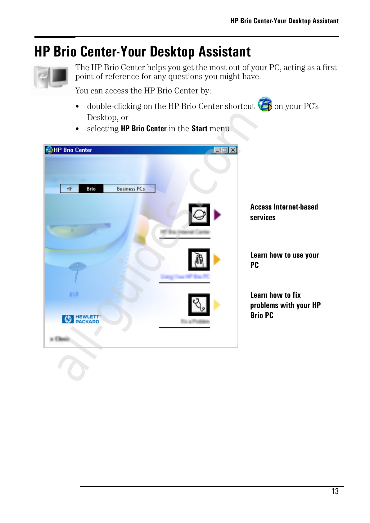
The HP Brio Center helps you get the most out of your PC, acting as a first
point of reference for any questions you might have.
You can access the HP Brio Center by:
• double-clicking on the HP Brio Center shortcut on your PC’s
Desktop, or
• selecting
HP Brio Center
in the
Start
menu.
Learn how to use your
PC
Learn how to fix
problems with your HP
Brio PC
Access Internet-based
services
All manuals and user guides at all-guides.com
all-guides.com
Page 22
HP Brio Center-Your Desktop Assistant
14
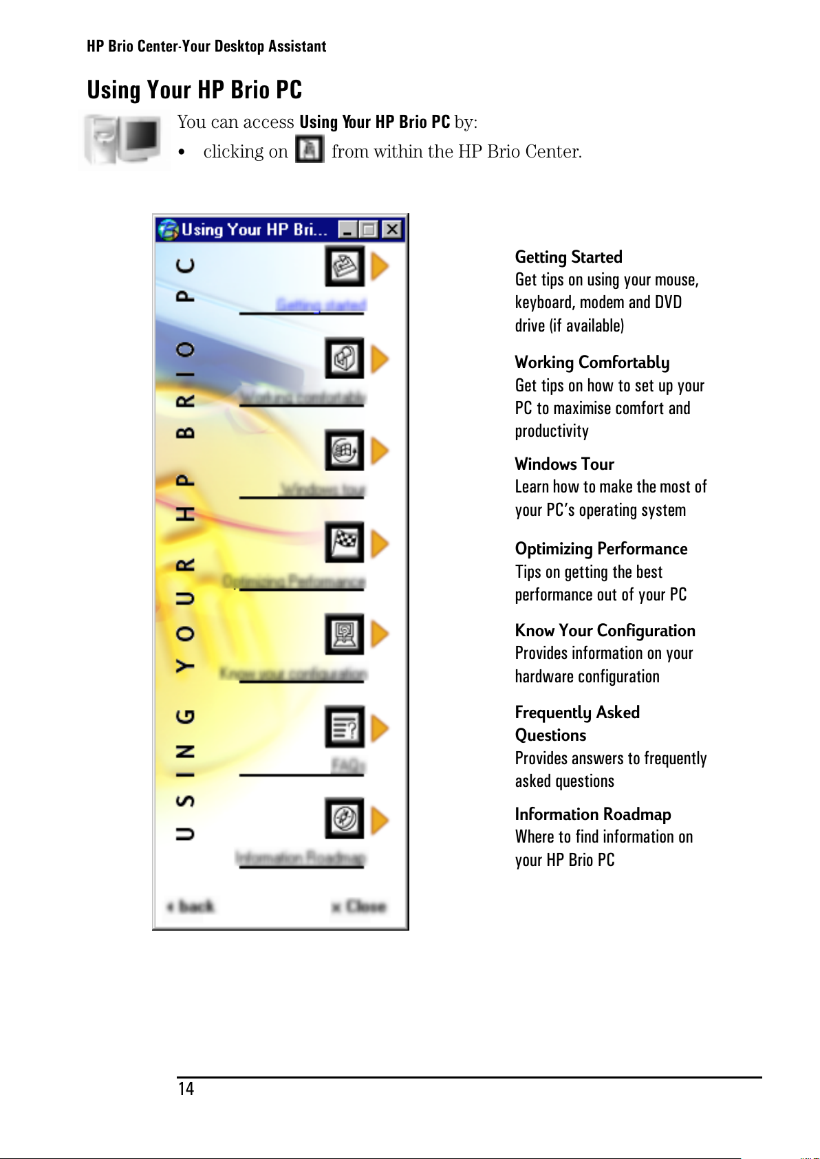
Using Your HP Brio PC
You can access UsingYourHPBrioPCby:
•
clicking on from within the HP Brio Center.
Working Comfortably
Gettipsonhowtosetupyour
PC to maximise comfort and
productivity
Windows Tour
Learn how to make the most of
your PC’s operating system
Getting Started
Get tips on using your mouse,
keyboard, modem and DVD
drive (if available)
Information Roadmap
Wheretofindinformationon
your HP Brio PC
Frequently Asked
Questions
Provides answers to frequently
asked questions
Optimizing Performance
Tips on getting the best
performance out of your PC
Know Your Configuration
Provides information on your
hardware configuration
All manuals and user guides at all-guides.com
Page 23
HP Brio Center-Your Desktop Assistant
15
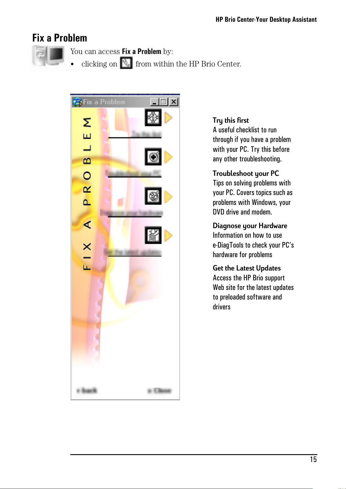
Fix a Problem
You can access Fix a Problem by:
•
clicking on from within the HP Brio Center.
Try this first
A useful checklist to run
through if you have a problem
with your PC. Try this before
any other troubleshooting.
Troubleshoot your PC
Tips on solving problems with
your PC. Covers topics such as
problems with Windows, your
DVD drive and modem.
Diagnose your Hardware
Informationonhowtouse
e-DiagTools to check your PC’s
hardware for problems
Get the Latest Updates
Access the HP Brio support
Web site for the latest updates
to preloaded software and
drivers
All manuals and user guides at all-guides.com
Page 24
Using Your Software
16
Using Your Software
When a program is installed on your PC, you can launch it by selecting it
from the
Start
menu on your
taskbar.
You can also create a desktop shortcut
so that you can launch a program directly from the desktop.
To create a desktop shortcut:
1 Open the
Program Files
folder in
Windows ExplorerorMy Computer
.
2 Find the file used to launch the program. The file name will end in
.exe
.
3 In the
File
menu, select
Create Shortcut
, then click on the newly created
file and drag it onto the PC’s desktop.
For more details on customizing Windows, refer to Windows online help,
accessible from the
Start
menu.
Refertoyourprogram’sdocumentationoronlinehelpforinformation
about its use.
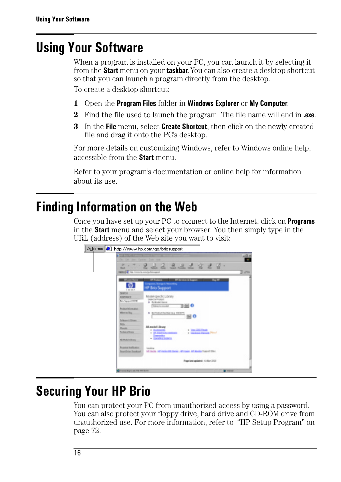
Finding Information on the Web
Once you have set up your PC to connect to the Internet, click on
Programs
in the
Start
menu and select your browser. You then simply type in the
URL (address) of the Web site you want to visit:
Securing Your HP Brio
You can protect your PC from unauthorized access by using a password.
You can also protect your floppy drive, hard drive and CD-ROM drive from
unauthorized use. For more information, refer to “HP Setup Program” on
page 72.
All manuals and user guides at all-guides.com
Page 25
3
Status
If You Have a Problem
This chapter describes how to avoid or solve problems with your HP Brio
PC.
What to Do First............................................................................ page 18
My HP Brio Doesn’t Start Properly ................................................ page 19
My HP Brio Isn’t Working Properly................................................. page 21
What Kind of Problem Is It?........................................................... page 22
Hardware Problems ....................................................................... page 23
Software Problems........................................................................ page 31
My HP Brio Has an Audio (Sound) Problem..................................... page 33
My HP Brio Detects an Error at Startup......................................... page 35
Frequently Asked Questions........................................................... page 41
Need More Help?........................................................................... page 41
HP Hardware Diagnostics (e-DiagTools) ......................................... page 42
HP Brio Assist CD-ROM................................................................. page 43
Support and Information Services .................................................. page 45
All manuals and user guides at all-guides.com
Page 26
What to Do First
18
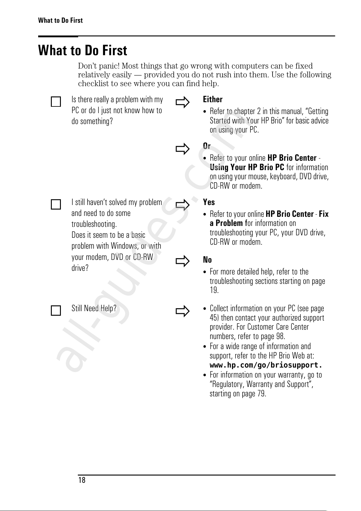
What to Do First
Don’t panic! Most things that go wrong with computers can be fixed
relatively easily — provided you do not rush into them. Use the following
checklist to see where you can find help.
Is there really a problem with my
PC or do I just not know how to
do something?
Either
•
Refer to chapter 2 in this manual, “Getting
Started with Your HP Brio” for basic advice
on using your PC.
Or
• Refer to your online
HP Brio Center
-
UsingYourHPBrioPC
for information
on using your mouse, keyboard, DVD drive,
CD-RW or modem.
I still haven’t solved my problem
andneedtodosome
troubleshooting.
Does it seem to be a basic
problem with Windows, or with
your modem, DVD or CD-RW
drive?
Yes
• Refer to your online
HP Brio Center-Fix
aProblem
for information on
troubleshooting your PC, your DVD drive,
CD-RW or modem.
No
•
For more detailed help, refer to the
troubleshooting sections starting on page
19.
Still Need Help?
•
Collect information on your PC (see page
45) then contact your authorized support
provider. For Customer Care Center
numbers, refer to page 98.
• For a wide range of information and
support, refer to the HP Brio Web at:
www.hp.com/go/briosupport.
•
For information on your warranty, go to
“Regulatory, Warranty and Support”,
starting on page 79.
All manuals and user guides at all-guides.com
all-guides.com
Page 27
My HP Brio Doesn’t Start Properly
19
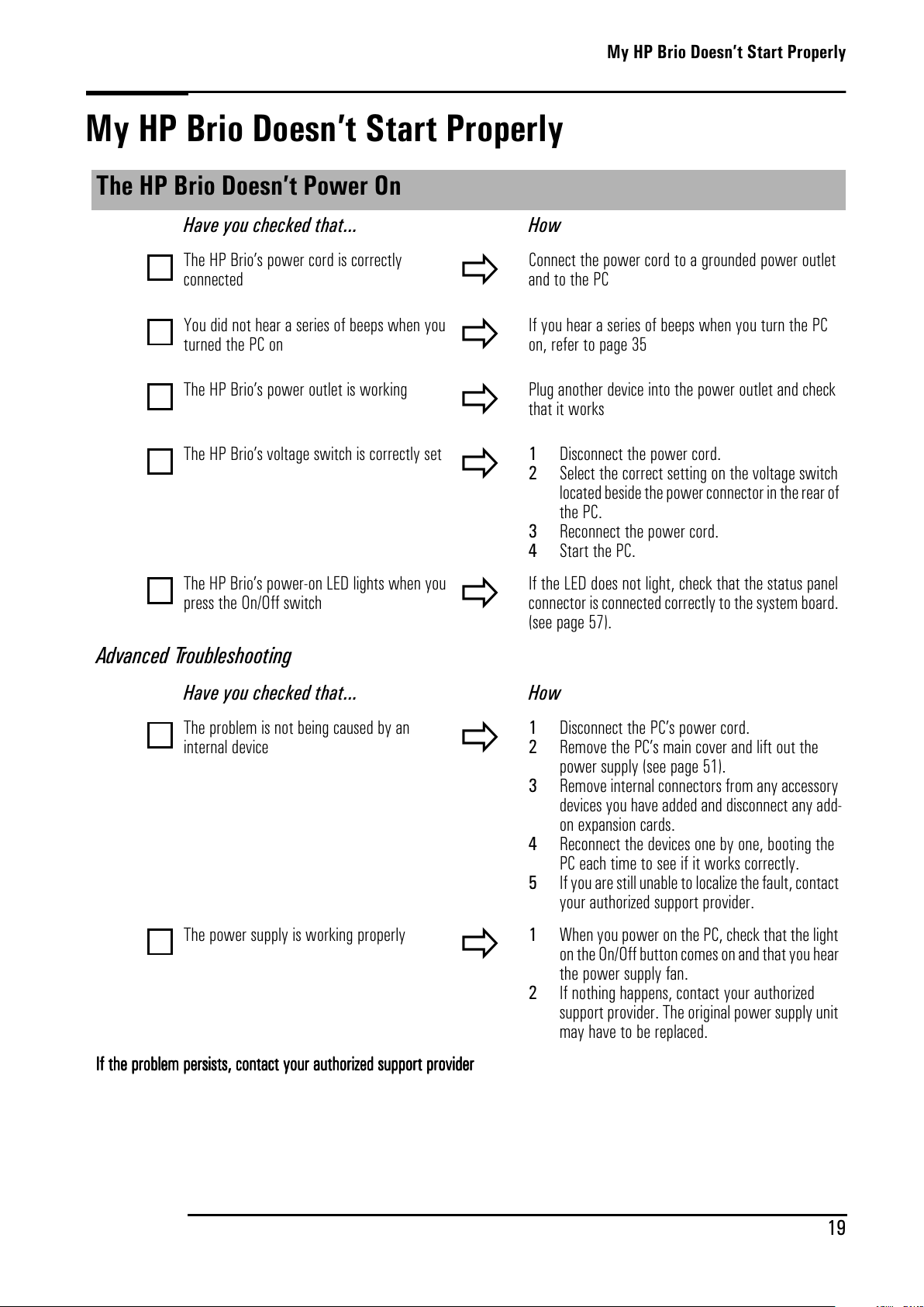
My HP Brio Doesn’t Start Properly
The HP Brio Doesn’t Power On
Have you checked that... How
The HP Brio’s power cord is correctly
connected
Connect the power cord to a grounded power outlet
andtothePC
You did not hear a series of beeps when you
turned the PC on
If you hear a series of beeps when you turn the PC
on, refer to page 35
The HP Brio’s power outlet is working
Plug another device into the power outlet and check
that it works
The HP Brio’s voltage switch is correctly set
1 Disconnect the power cord.
2 Select the correct setting on the voltage switch
located beside the power connector in the rearof
the PC.
3 Reconnect the power cord.
4 Start the PC.
The HP Brio’s power-on LED lights when you
press the On/Off switch
If the LED does not light, check that the status panel
connector is connected correctly to the system board.
(see page 57).
Advanced Troubleshooting
Have you checked that... How
The problem is not being caused by an
internal device
1 Disconnect the PC’s power cord.
2 Remove the PC’s main cover and lift out the
power supply (see page 51).
3 Remove internal connectors from any accessory
devices you have added and disconnect any add-
on expansion cards.
4 Reconnect the devices one by one, booting the
PC each time to see if it works correctly.
5 If you are still unable to localize the fault, contact
your authorized support provider.
The power supply is working properly
1 When you power on the PC, check that the light
on the On/Off button comes on and that you hear
the power supply fan.
2 If nothing happens, contact your authorized
support provider. The original power supply unit
mayhavetobereplaced.
IIIIfffftttthhhheeeepppprrrroooobbbblllleeeemmmmppppeeeerrrrssssiiiissssttttssss,,,,ccccon
onon
onttttaaaaccccttttyyyyoooouuuurrrraaaauuuutttthhhhoooorrrriiiizzzzeeeeddddssssuuuupppppo
popo
porrrrttttpppprrrroooovvvviiiiddddeeeerrrr
All manuals and user guides at all-guides.com
Page 28
My HP Brio Doesn’t Start Properly
20
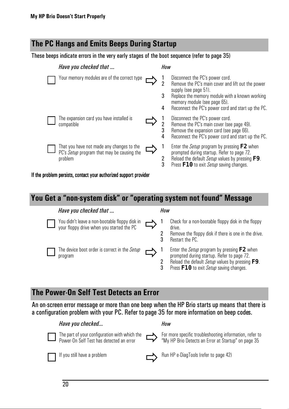
The PC Hangs and Emits Beeps During Startup
These beeps indicate errors in the very early stages of the boot sequence (refer to page 35)
Have you checked that ...
How
Your memory modules are of the correct type
1 Disconnect the PC’s power cord.
2 Remove the PC’s main cover and lift out the power
supply(seepage51).
3 Replace the memory module with a known working
memory module (see page 65).
4 Reconnect the PC’s power cord and start up the PC.
The expansion card you have installed is
compatible
1 Disconnect the PC’s power cord.
2 Remove the PC’s main cover (see page 49).
3 Remove the expansion card (see page 66).
4 Reconnect the PC’s power cord and start up the PC.
That you have not made any changes to the
PC’s Setup program that may be causing the
problem
1 Enter the Setup program by pressing F2 when
prompted during startup. Refer to page 72.
2 Reload the default Setup values by pressing F9.
3 Press F10 to exit Setup saving changes.
IIIIfffftttthhhheeeepppprrrroooobbbblllleeeemmmmppppeeeerrrrssssiiiissssttttssss,,,,ccccoooonnnnttttaaaaccccttttyyyyoooouuuurrrraaaauuuutttthhhhoooorrrriiiizzzzeeeeddddssssuuuuppppppppoooort
rtrt
rt pppprrrroooovvvviiiiddddeeeerrrr
You Get a “non-system disk” or ”operating system not found” Message
Have you checked that ...
How
You didn’t leave a non-bootable floppy disk in
your floppy drive when you started the PC
1 Check for a non-bootable floppy disk in the floppy
drive.
2 Remove the floppy disk if there is one in the drive.
3 Restart the PC.
The device boot order is correct in the Setup
program
1 Enter the Setup program by pressing F2 when
prompted during startup. Refer to page 72.
2 Reload the default Setup values by pressing F9.
3 Press F10 to exit Setup saving changes.
The Power-On Self Test Detects an Error
An on-screen error message or more than one beep when the HP Brio starts up means that there is
a configuration problem with your PC. Refer to page 35 for more information on beep codes.
Have you checked...
How
The part of your configuration with which the
Power-On Self Test has detected an error
For more specific troubleshooting information, refer to
“My HP Brio Detects an Error at Startup” on page 35
If you still have a problem
Run HP e-DiagTools (refer to page 42)
All manuals and user guides at all-guides.com
Page 29
My HP Brio Isn’t Working Properly
21
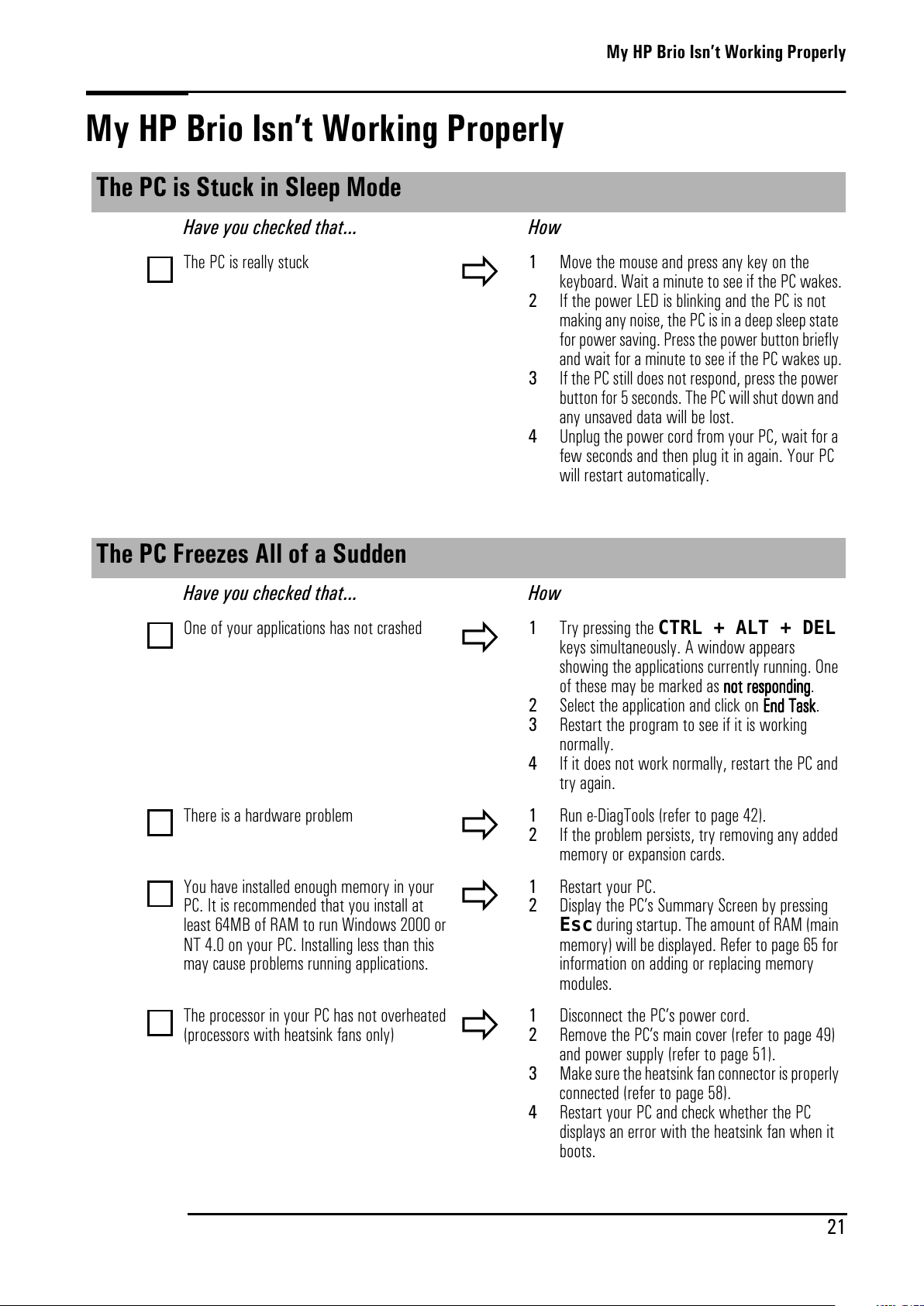
My HP Brio Isn’t Working Properly
The PC is Stuck in Sleep Mode
Have you checked that... How
The PC is really stuck
1 Move the mouse and press any key on the
keyboard. Wait a minute to see if the PC wakes.
2 If the power LED is blinking and the PC is not
making any noise, the PC is in a deep sleep state
for power saving. Press the power button briefly
and wait for a minute to see if the PC wakes up.
3 If the PC still does not respond, press the power
button for 5 seconds. The PC will shut down and
any unsaved data will be lost.
4 Unplug the power cord from your PC, wait for a
few seconds and then plug it in again. Your PC
will restart automatically.
The PC Freezes All of a Sudden
Have you checked that... How
One of your applications has not crashed
1 Try pressing the CTRL + ALT + DEL
keys simultaneously. A window appears
showing the applications currently running. One
of these may be marked as nnnnoooottttrrrreeeessssppppon
onon
onddddiiiing
ngng
ng.
2 Select the application and click on EEEEnnnnddddTTTTaaaasssskkkk.
3 Restart the program to see if it is working
normally.
4 If it does not work normally, restart the PC and
try again.
There is a hardware problem
1 Run e-DiagTools (refer to page 42).
2 If the problem persists, try removing any added
memory or expansion cards.
You have installed enough memory in your
PC. It is recommended that you install at
least 64MB of RAM to run Windows 2000 or
NT 4.0 on your PC. Installing less than this
may cause problems running applications.
1 Restart your PC.
2 Display the PC’s Summary Screen by pressing
Escduring startup. The amount of RAM (main
memory) will be displayed. Refer to page 65 for
information on adding or replacing memory
modules.
TheprocessorinyourPChasnotoverheated
(processors with heatsink fans only)
1 Disconnect the PC’s power cord.
2 Remove the PC’s main cover (refer to page 49)
and power supply (refer to page 51).
3 Make sure the heatsink fan connector is properly
connected (refer to page 58).
4 Restart your PC and check whether the PC
displays an error with the heatsink fan when it
boots.
All manuals and user guides at all-guides.com
Page 30
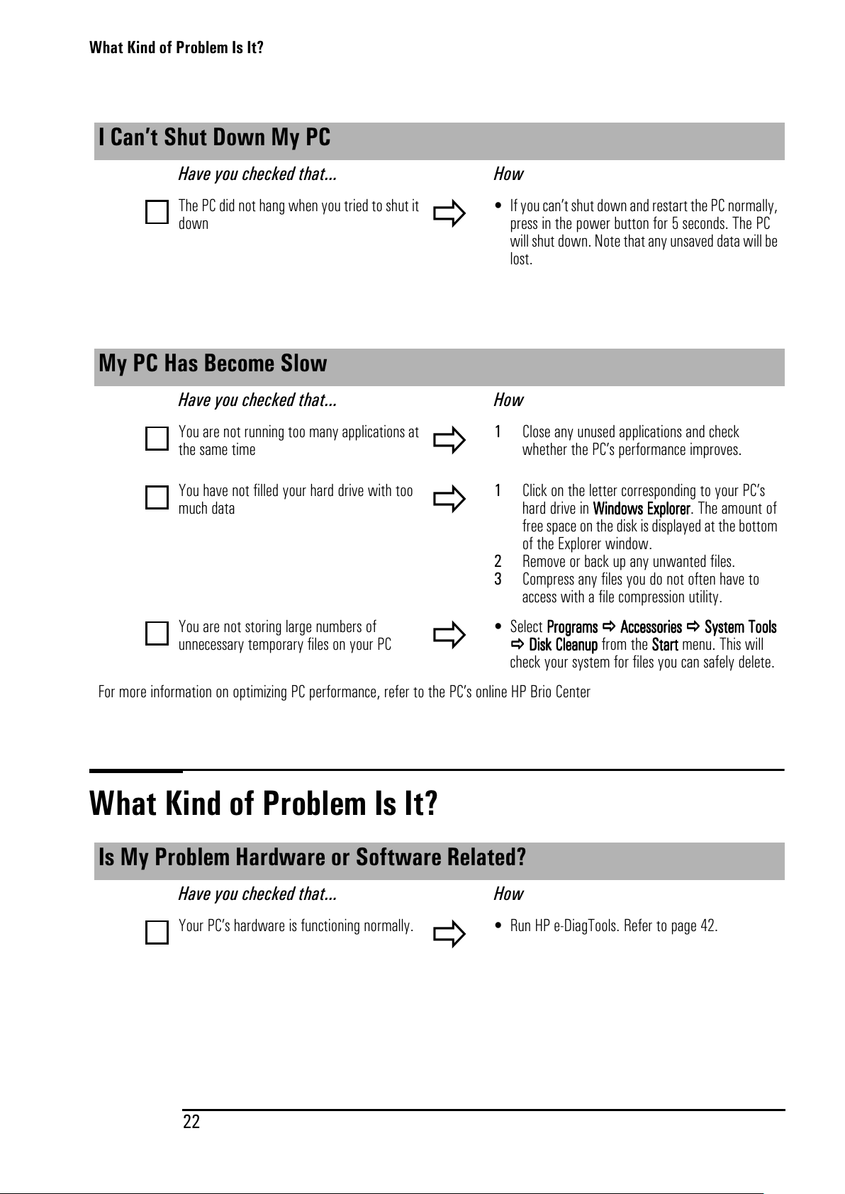
What Kind of Problem Is It?
22
What Kind of Problem Is It?
I Can’t Shut Down My PC
Have you checked that... How
The PC did not hang when you tried to shut it
down
• If you can’t shut down and restart the PC normally,
press in the power button for 5 seconds. The PC
will shut down. Note that any unsaved data will be
lost.
My PC Has Become Slow
Have you checked that... How
You are not running too many applications at
thesametime
1 Close any unused applications and check
whether the PC’s performance improves.
You have not filled your hard drive with too
much data
1 Click on the letter corresponding to your PC’s
hard drive in WWWWiiiinnnndo
dodo
dowwwwssssEEEExxxxpppplllloooorrrreeeerrrr. The amount of
free space on the disk is displayed at the bottom
of the Explorer window.
2 Remove or back up any unwanted files.
3 Compress any files you do not often have to
access with a file compression utility.
You are not storing large numbers of
unnecessary temporary files on your PC
• Select PPPPrrrrog
ogog
ogrrrraaaammmmssss AAAAcccccccceeeess
ssss
ssoooorrrriiiieeeessss SSSSyyyysssstttteeeemmmmTTTToooooooollllssss
DDDDiiiisssskkkkCCCCllllea
eaea
eanu
nunu
nuppppfromtheSSSSttttaaaart
rtrt
rt menu. This will
check your system for files you can safely delete.
For more information on optimizing PC performance, refer to the PC’s online HP Brio Center
Is My Problem Hardware or Software Related?
Have you checked that... How
Your PC’s hardware is functioning normally.
• Run HP e-DiagTools. Refer to page 42.
All manuals and user guides at all-guides.com
Page 31
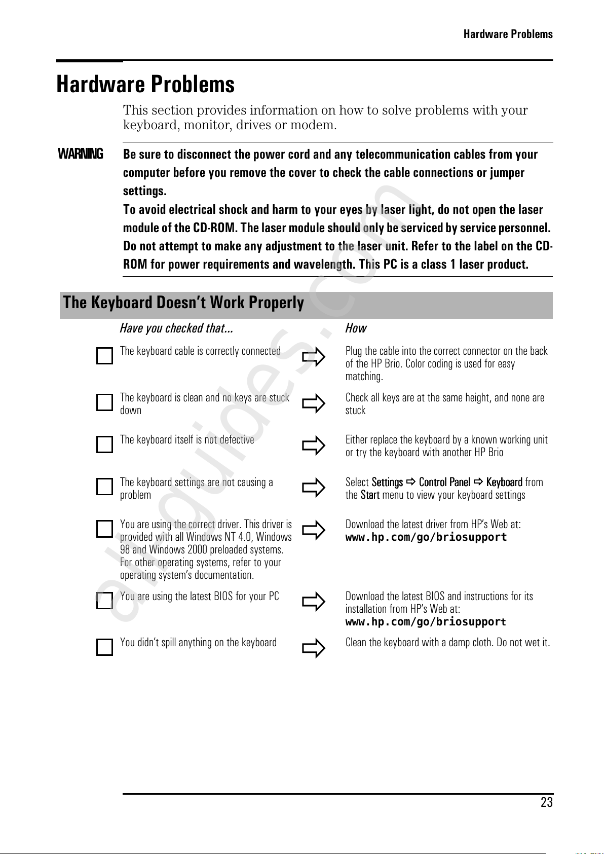
Hardware Problems
23
Hardware Problems
This section provides information on how to solve problems with your
keyboard, monitor, drives or modem.
WARNING Be sure to disconnect the power cord and any telecommunication cables from your
computer before you remove the cover to check the cable connections or jumper
settings.
To avoid electrical shock and harm to your eyes by laser light, do not open the laser
module of the CD-ROM. The laser module should only be serviced by service personnel.
Do not attempt to make any adjustment to the laser unit. Refer to the label on the CD-
ROM for power requirements and wavelength. This PC is a class 1 laser product.
The Keyboard Doesn’t Work Properly
Have you checked that... How
The keyboard cable is correctly connected
Plug the cable into the correct connector on the back
of the HP Brio. Color coding is used for easy
matching.
The keyboard is clean and no keys are stuck
down
Check all keys are at the same height, and none are
stuck
The keyboard itself is not defective
Either replace the keyboard by a known working unit
or try the keyboard with another HP Brio
The keyboard settings are not causing a
problem
Select SSSSeeeett
tttt
ttiiiinnnnggggssss CCCCoooonnnntr
trtr
troooollllPPPPaaaannnneeeellll KKKKey
eyey
eybo
bobo
boaaaarrrrddddfrom
the SSSSttttaaaart
rtrt
rt menu to view your keyboard settings
You are using the correct driver. This driver is
provided with all Windows NT 4.0, Windows
98 and Windows 2000 preloaded systems.
For other operating systems, refer to your
operating system’s documentation.
Download the latest driver from HP’s Web at:
www.hp.com/go/briosupport
You are using the latest BIOS for your PC
Download the latest BIOS and instructions for its
installation from HP’s Web at:
www.hp.com/go/briosupport
You didn’t spill anything on the keyboard
Cleanthekeyboardwithadampcloth.Donotwetit.
All manuals and user guides at all-guides.com
all-guides.com
Page 32
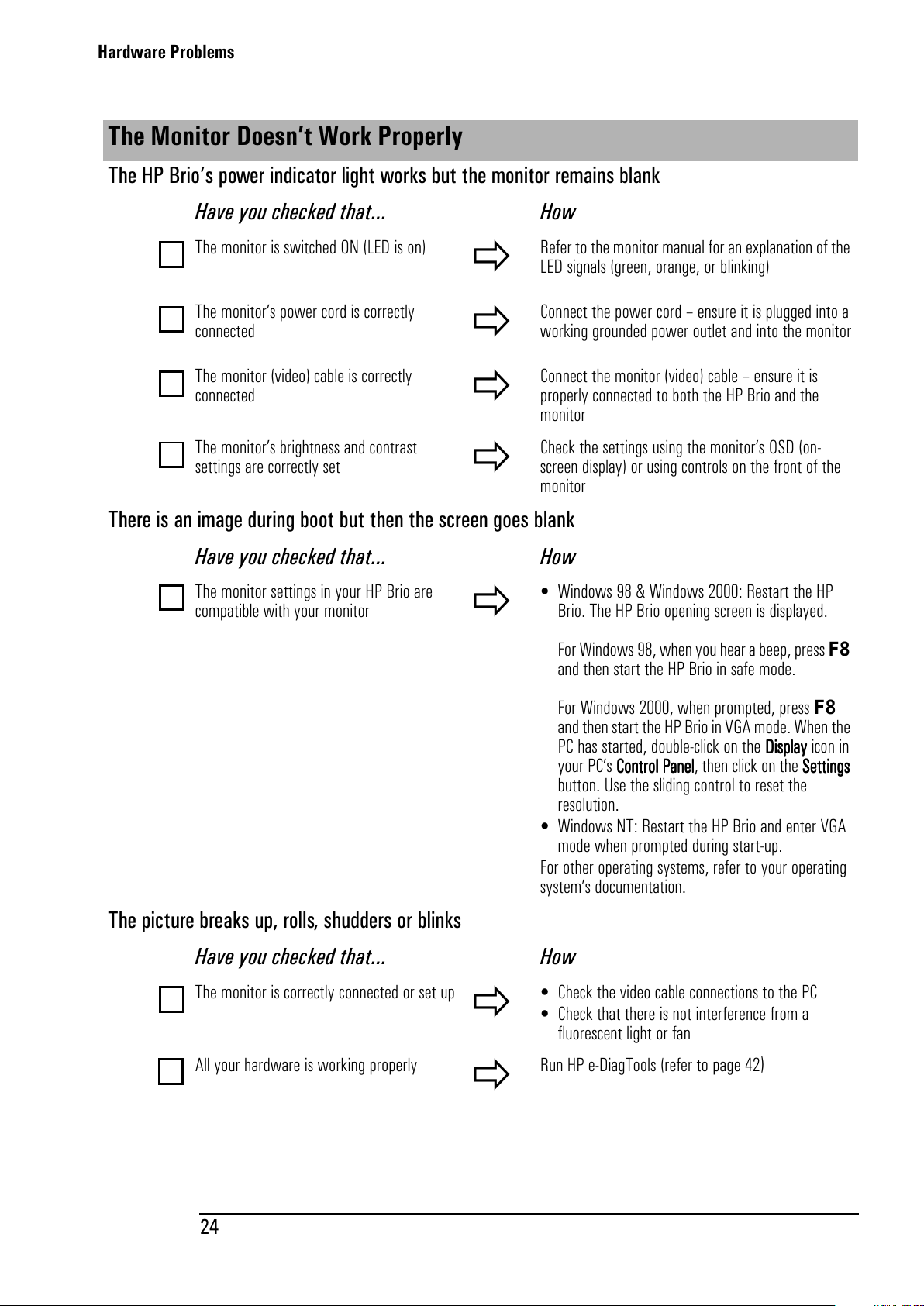
Hardware Problems
24
The Monitor Doesn’t Work Properly
The HP Brio’s power indicator light works but the monitor remains blank
Have you checked that... How
The monitor is switched ON (LED is on)
Refer to the monitor manual for an explanation of the
LED signals (green, orange, or blinking)
The monitor’s power cord is correctly
connected
Connect the power cord – ensure it is plugged into a
working grounded power outlet and into the monitor
The monitor (video) cable is correctly
connected
Connect the monitor (video) cable – ensure it is
properly connected to both the HP Brio and the
monitor
The monitor’s brightness and contrast
settings are correctly set
Check the settings using the monitor’s OSD (on-
screen display) or using controls on the front of the
monitor
There is an image during boot but then the screen goes blank
Have you checked that... How
The monitor settings in your HP Brio are
compatible with your monitor
• Windows 98 & Windows 2000: Restart the HP
Brio. The HP Brio opening screen is displayed.
For Windows 98, when you hear a beep, press F8
and then start the HP Brio in safe mode.
For Windows 2000, when prompted, press F8
and then start the HP Brio in VGA mode. When the
PC has started, double-click on the DDDDiiiissssppppllllaaaayyyyiconin
your PC’s CCCCoooonnnntr
trtr
troooollllPPPPaaaannnneeeellll, then click on the SSSSeeeett
tttt
ttiiiinnnnggggssss
button. Use the sliding control to reset the
resolution.
• Windows NT: Restart the HP Brio and enter VGA
mode when prompted during start-up.
For other operating systems, refer to your operating
system’s documentation.
The picture breaks up, rolls, shudders or blinks
Have you checked that... How
The monitor is correctly connected or set up
• Check the video cable connections to the PC
• Check that there is not interference from a
fluorescent light or fan
All your hardware is working properly
Run HP e-DiagTools (refer to page 42
)
All manuals and user guides at all-guides.com
Page 33
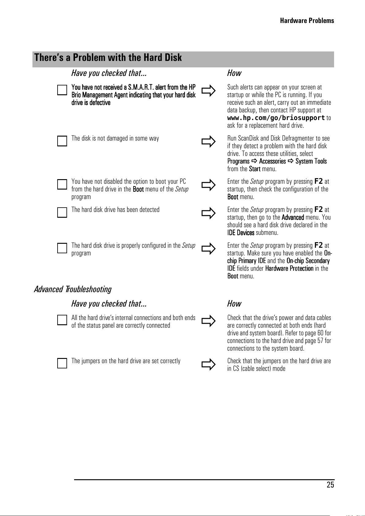
Hardware Problems
25
There’s a Problem with the Hard Disk
Have you checked that... How
YYYYoooouuuuhhhhaaaavvvveeeeno
nono
nottttrrrreeeecccceeeeiiiivvvveeeeddddaaaaSSSS....MMMM....AAAA....RRRR....TTTT....aaaalllleeeerrrrttttffffrrrroooommmmtttthhhheeeeHHHHPPPP
BBBBrrrriiiiooooMMMMaaaannnnaaaaggggeeeemmmmeeeennnnttttAAAAggggeeeennnnttttiiiind
ndnd
ndiiiiccccaaaattttiiiinnnnggggtttthhhhaaaattttyyyyou
ouou
ourrrrhhhhaaaarrrrd d
dddd
ddiiiisssskkkk
ddddrrrriiiivvvveeeeiiiissssddddeeeeffffeeeeccccttttiiiivvvveeee
Such alerts can appear on your screen at
startup or while the PC is running. If you
receive such an alert, carry out an immediate
data backup, then contact HP support at
www.hp.com/go/briosupport
to
ask for a replacement hard drive.
The disk is not damaged in some way
Run ScanDisk and Disk Defragmenter to see
if they detect a problem with the hard disk
drive. To access these utilities, select
PPPPrrrrog
ogog
ogrrrraaaammmmssss AAAAcccccccceeeess
ssss
ssoooorrrriiiieeeessss SSSSyyyysssstttteeeemmmmTTTToooooooollllssss
from the SSSSttttaaaart
rtrt
rt menu.
You have not disabled the option to boot your PC
from the hard drive in the BBBBoooooooottttmenuoftheSetup
program
Enter the Setup program by pressing F2 at
startup, then check the configuration of the
BBBBoooooooottttmenu.
The hard disk drive has been detected
Enter the Setup program by pressing F2 at
startup, then go to the AAAAddddvvvvaaaannnncccceeeeddddmenu.You
should see a hard disk drive declared in the
IIIIDDDDEEEEDDDDeeeevvvviiiicccceeeessss submenu.
The hard disk drive is properly configured in the Setup
program
Enter the Setup program by pressing F2 at
startup. Make sure you have enabled the OOOOnnnn----
cccchhhhiiiippppPPPPrrrriiiimmmmaaaarrrryyyyIIIIDDDDEEEEandtheOOOOnnnn----cccchhhhiiiippppSSSSeeeeccccoooonnnnddddaaaarrrryyyy
IIIIDDDDEEEE fields under HHHHaaaarrrrddddwwwwaaaarrrreeeePPPPrrrrooootttteeeeccccttttiiiioooonnnninthe
BBBBoooooooottttmenu.
Advanced Troubleshooting
Have you checked that...
How
All the hard drive’s internal connections and both ends
of the status panel are correctly connected
Check that the drive’s power and data cables
are correctly connected at both ends (hard
drive and system board). Refer to page 60 for
connections to the hard drive and page 57 for
connections to the system board.
The jumpers on the hard drive are set correctly
Check that the jumpers on the hard drive are
in CS (cable select) mode
All manuals and user guides at all-guides.com
Page 34
Hardware Problems
26
There’s a Problem with the Floppy Drive
Have you checked that... How
You are using a formatted diskette and it is inserted
correctly
You will receive an on-screen error if the
diskette is not properly formatted
The floppy is clean
Use a diskette cleaning kit (see your PC
dealer)
The Setup program is correctly configured for your
floppy drive
Enter the Setup program by pressing F2 at
startup, then:
• Go to the AAAAddddvvvvaaaannnncccceeeedddd menu. You should see
a hard disk drive declared in the FFFFlllleeeexxxxiiiibbbblllleeee
DDDDiiiisssskkkkDDDDrrrriiiivvvveeee submenu.
The hardware is working properly
Run e-DiagTools to see if it detects a problem
with the floppy drive (refer to page 42)
Advanced Troubleshooting
Have you checked that...
How
The drive’s power and data cables are correctly
connected
Check that the drive’s power and data cables
are correctly connected at both ends (floppy
drive and system board). Refer to page 59 for
connections to the floppy drive and page 57
for connections to the system board.
All manuals and user guides at all-guides.com
Page 35
Hardware Problems
27
There’s a Problem with the CD-ROM, CD-RW or DVD Drive
Have you checked that...
How
There is a disc inserted in the drive
• Click on the drive letter assigned to your
drive in Windows Explorer. If you receive
a message such as DDDD::::\\\\iiiissssnnnnooootttt
aaaacccccccceeeess
ssss
ssiiiibbbblllleeee////ddddeeeevvvviiiicccceeeeiiiissssno
nono
nottttrrrreeeeaaaaddddyyyy, this means
thereisnodiscinthedrive.
• Open the drive and check whether there
is a disc inside.
The Setup program is correctly configured for your
drive
Enter the Setup program by pressing F2 at
startup, then:
• Make sure you have enabled the OOOOnnnn----cccchhhhiiiipppp
PPPPrrrriiiimmmmaaaarrrryyyyIIIIDDDDEEEEandtheOOOOnnnn----cccchhhhiiiippppSSSSeeeeccccon
onon
onddddaaaarrrryyyy
IIIIDDDDEEEE fields under HHHHaaaarrrrddddwwwwaaaarrrreeeePPPPrrrrooootttteeeeccccttttiiiioooonnnnin
the BBBBoooooooottttmenu.
• Go to the AAAAddddvvvvaaaannnncccceeeedddd menu. You should
see a CD-ROM, CD-RW or DVD-ROM
drive declared in the IIIIDDDDEEEEDDDDeeeevvvviiiicccceeeessss
submenu.
The device boot order is set correctly in the Setup
program
• Enter the Setup program by pressing F2
at startup, then go to the BBBBoooooooottttmenu.If
youintendtobootfromtheCD-ROM
drive, you should place CCCCDDDD----RRRROOOOMMMMbefore
HHHHDDDDDDDDintheBBBBooooooootttt BBBBoo
oooo
oottttDDDDeeeevvvviiiicccceeeePPPPrrrriiiioooorrrriiiittttyyyy
submenu.
The hardware is working properly
Run e-DiagTools to see if it detects a
problem with the drive (refer to page 42).
Advanced Troubleshooting
Have you checked that...
How
All cables (data, power and audio) have been properly
connected both to the drive and to the system board.
Check that the drive’s power and data
cables are correctly connected at both ends
(drive and system board). Refer to page 62
for connections to the drive and page 57 for
connections to the system board.
The jumpers on the drive are set correctly
Check that the jumpers on the hard drive
are in CS (cable select) mode
FFFFoooorrrrmmmmoooorrrreeeeiiiinnnnffffoooorrrrmmmmaaaattttiiiioooonnnnoooonnnnuuuussssiiiinnnnggggaaaand
ndnd
nd tr
trtr
trooooub
ubub
ublllleeeessssho
hoho
hooooottttiiiinnnng y
gygy
gyoooouuuurrrrDDDDVVVVDDDDddddrrrriiiivvvveeee,,,,rrrreeeeffffeeeer t
rtrt
rtooootttthhhheeeePPPPCCCC’’’’sssson
onon
onli
lili
linnnneeeeHHHHPPPPBBBBrrrriiiiooooCCCCen
enen
entttteeeerrrr
All manuals and user guides at all-guides.com
Page 36
Hardware Problems
28
The DVD Drive Doesn’t Play DVD Video
Have you checked that...
The DVD disc you are trying to play and your DVD drive have the same regional code setting. Your DVD drive’s
regional code setting is set by the first DVD disc you insert in the drive. After several uses the regional drive
becomes fixed and cannot subsequently be changed.
You have either a hardware or a software MPEG decoder installed on your system
Your PC’s hardware and software configuration supports the playing of DVDs. The following configuration is
recommended:
• At least an Intel Celeron processor with a minimum clock speed of 400 MHz.
• 64MB of memory (Windows 2000, Windows 98)
• Display settings of 800 x 600 pixels, High Color (16-bit).
You are using the latest drivers. These can be downloaded from the HP Brio support Web site at:
www.hp.com/go/briosupport.
You are not trying to play DVD video under Windows NT 4.0. DVD video is not supported by this operating
system.
You have enabled DMA mode on the Secondary IDE channel in the Setup program, accessed by pressing F2
during startup.
For more information on using and troubleshooting DVD, refer to the PC’s online HP Brio Center
The CD-ROM, CD-RW or DVD Drive Doesn’t Open
What to Do...
1 If you have difficulty removing a disc from the drive (during a power failure for example), you can use the
manual eject button.
With a thin, solid rod, such as the end of a paper clip, push the drive’s manual eject button
2 The drive door will be released, opening slightly. Carefully pull it open fully and retrieve the disc.
3 To close the drive door, push it gently closed without forcing it. The drive door may not close completely
until it is fully functional (for example, when the power comes back on).
All manuals and user guides at all-guides.com
all-guides.com
Page 37
Hardware Problems
29
The Printer Doesn’t Work
The Printer Will Not Print
Have you checked that... How
The printer is on
• Check the power and data cables are correctly
connected and press the printer’s power button.
There is paper in the printer
• Check the printer’s paper tray
Youdidn’tplugintheprinter’sparalleldatacable
(where applicable) when the PC was already on
1
Shut the PC down, then restart it.
2
Try to print again.
The correct printer driver is installed
• Check that the correct printer driver is installed on
your PC by clicking on the SSSSttttaaaart
rtrt
rt menu, then
selecting SSSSeeeett
tttt
ttiiiinnnnggggssss PPPPrrrriiiinnnntttteeeerrrrssss. Your printer’s driver
should be displayed in the Printers window.
The printer is configured correctly
• Click on the SSSSttttaaaart
rtrt
rt menu, then select SSSSeeeett
tttt
ttiiiinnnnggggssss
PPPPrrrriiiinnnntttteeeerrrrssss. Right-click on the icon for the printer
youwanttouseandensurethatSSSSeeeettttaaaassssddddeeeeffffaaaauuuullllttttis
selected and that the printer is set to work online.
• If the printer is on your network, you can set it up
by browsing for it in NNNNeeeettttwwwwoooorrrrkkkkNNNNeeeeiiiigh
ghgh
ghbbbboooorrrrhhhhoooooooodddd,
clicking on the printer’s icon, then clicking on IIIInnnnssssttttaaaall
llll
ll
in the FFFFil
ilil
ileeeemenu.
• Print out a test page to test the printer
The parallel port is configured correctly in the PC’s
Setup program
1
Switch the PC OFF then ON.
2
When the message PPPPrrrreeeess
ssss
ss FFFF2222ttttooooEEEEnnnntttteeeerrrrSSSSeeeettttuuuupppp
appears, press the F2 key. Check that
IIIInnnntttteeeeggggrrrraaaatttteeeeddddIIII////OOOOPPPPoooorrrrttttssss PPPPaaaarrrraaaall
llll
lleeeellllPPPPoooort
rtrt
rt is not
disabled in the AAAAddddvvvvaaaannnncccceeeedddd menu.
3
This setting should be AAAAuuuuttttoooo.
The Printer Prints Garbled Information
Have you checked that... How
The correct printer driver is installed
• Check that the correct driver is installed on your PC
by clicking on the SSSSttttaaaart
rtrt
rt menu, then selecting
SSSSeeeettttttttiiiing
ngng
ngssss PPPPrrrriiiinnnntttteeeerrrrssss. The driver for your printer
should be displayed in the Printers window that
appears.
The printer’s data cables are connected properly
• Check the cables and, if it still does not work, check
the product documentation
All manuals and user guides at all-guides.com
Page 38
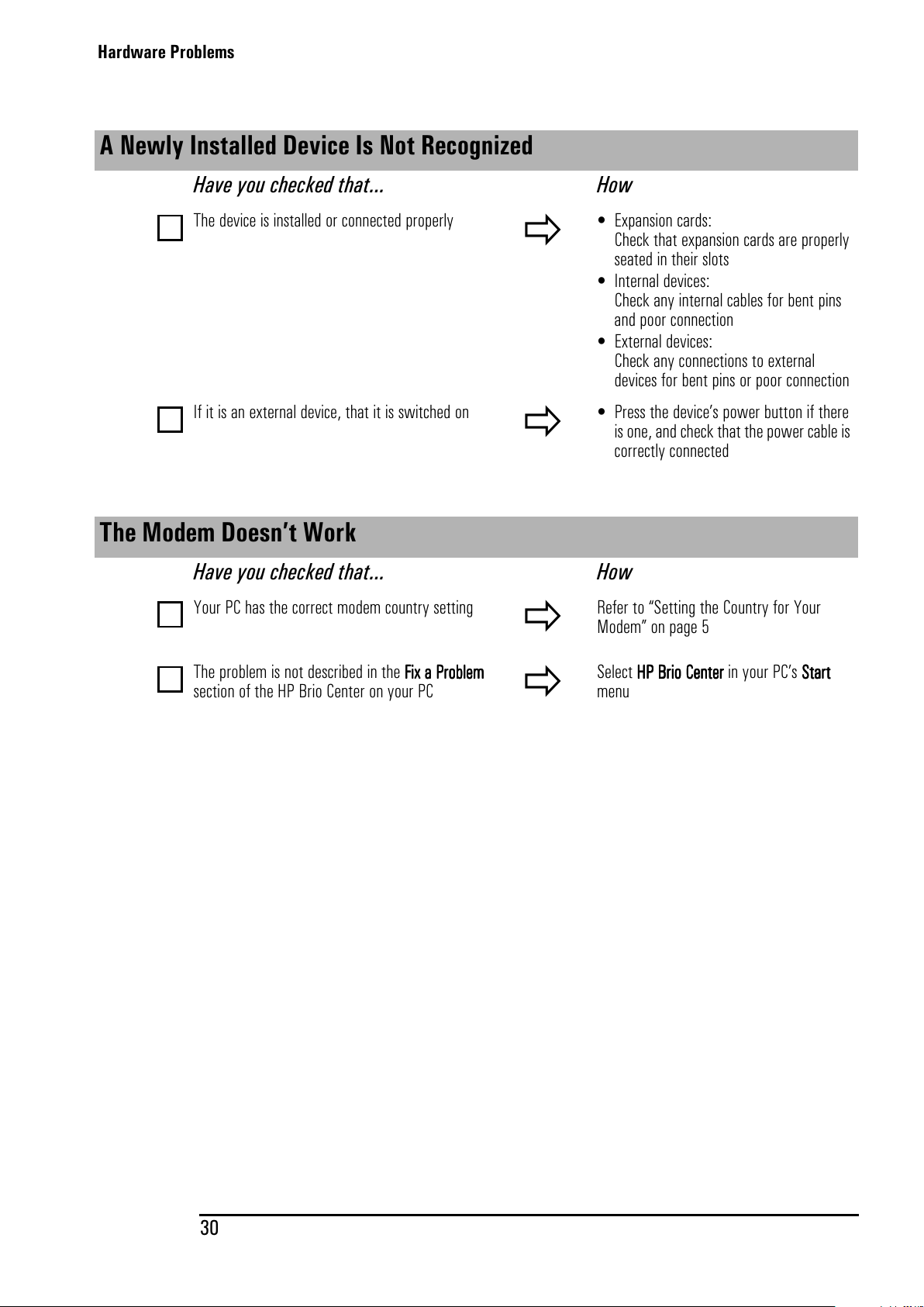
Hardware Problems
30
A Newly Installed Device Is Not Recognized
Have you checked that...
How
The device is installed or connected properly
• Expansion cards:
Check that expansion cards are properly
seated in their slots
• Internal devices:
Check any internal cables for bent pins
and poor connection
• External devices:
Check any connections to external
devices for bent pins or poor connection
If it is an external device, that it is switched on
• Press the device’s power button if there
is one, and check that the power cable is
correctly connected
The Modem Doesn’t Work
Have you checked that...
How
Your PC has the correct modem country setting
Refer to “Setting the Country for Your
Modem” on page 5
The problem is not described in the FFFFiiiixxxxaaaaPPPPrrrrob
obob
oblllleeeemmmm
section of the HP Brio Center on your PC
Select HHHHPPPPBBBBrrrriiiiooooCCCCeeeennnntttteeeerrrrinyourPC’sSSSSttttaaaart
rtrt
rt
menu
All manuals and user guides at all-guides.com
Page 39
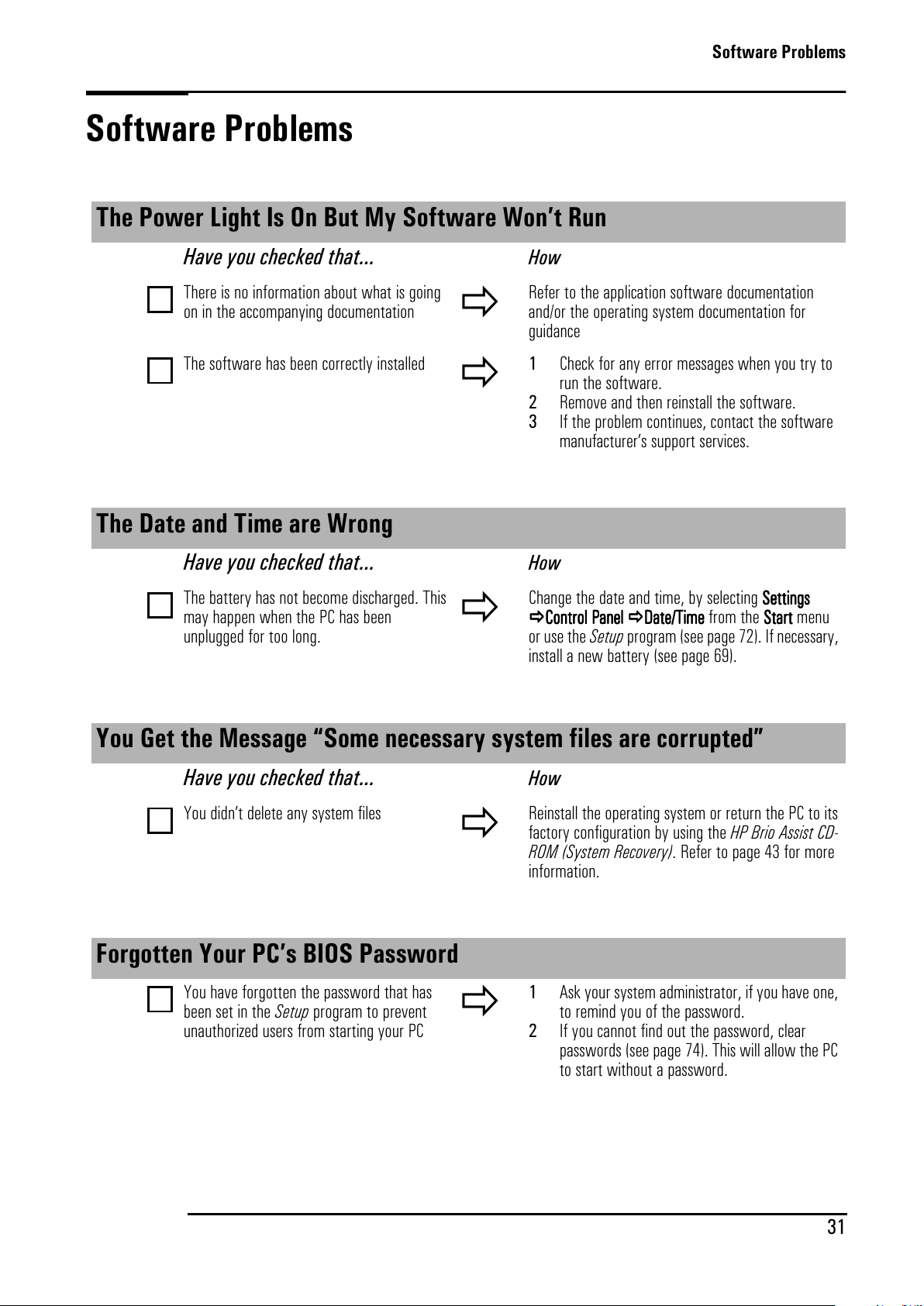
Software Problems
31
Software Problems
The Power Light Is On But My Software Won’t Run
Have you checked that... How
There is no information about what is going
on in the accompanying documentation
Refer to the application software documentation
and/or the operating system documentation for
guidance
The software has been correctly installed
1 Check for any error messages when you try to
run the software.
2 Remove and then reinstall the software.
3 If the problem continues, contact the software
manufacturer’s support services.
TheDateandTimeareWrong
Have you checked that... How
The battery has not become discharged. This
may happen when the PC has been
unplugged for too long.
Change the date and time, by selecting SSSSeeeett
tttt
ttiiiinnnnggggssss
CCCCoooonnnntr
trtr
troooollllPPPPaaaannnneeeellll DDDDaaaatttteeee////TTTTiiiimmmmeeeefromtheSSSSttttaaaart
rtrt
rt menu
or use the Setup program (see page 72). If necessary,
install a new battery (see page 69).
You Get the Message “Some necessary system files are corrupted”
Have you checked that... How
You didn’t delete any system files
Reinstall the operating system or return the PC to its
factory configuration by using the HP Brio Assist CD-
ROM (System Recovery). Refer to page 43 for more
information.
Forgotten Your PC’s BIOS Password
You have forgotten the password that has
been set in the Setup program to prevent
unauthorized users from starting your PC
1 Ask your system administrator, if you have one,
to remind you of the password.
2 If you cannot find out the password, clear
passwords (see page 74). This will allow the PC
to start without a password.
All manuals and user guides at all-guides.com
Page 40
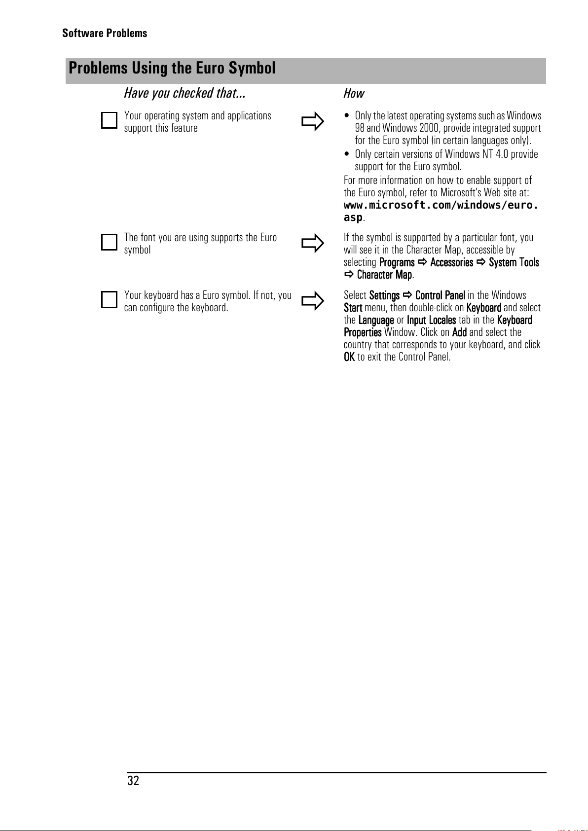
Software Problems
32
Problems Using the Euro Symbol
Have you checked that... How
Your operating system and applications
support this feature
• Only the latest operating systems suchas Windows
98 and Windows 2000, provide integrated support
for the Euro symbol (in certain languages only).
• Only certain versions of Windows NT 4.0 provide
support for the Euro symbol.
For more information on how to enable support of
the Euro symbol, refer to Microsoft’s Web site at:
www.microsoft.com/windows/euro.
asp
.
The font you are using supports the Euro
symbol
If the symbol is supported by a particular font, you
will see it in the Character Map, accessible by
selecting PPPPrrrrooooggggrrrraaaammmmssss AAAAcccccccceeeessssssssoooorrrriiiieeeessss SSSSyyyysssstttteeeemmmmTTTToo
oooo
oollllssss
CCCChhhhaaaarrrraaaacccctttteeeerrrrMMMMaaaapppp.
Your keyboard has a Euro symbol. If not, you
can configure the keyboard.
Select SSSSeeeett
tttt
ttiiiinnnnggggssss CCCCoooonnnnttttrrrroooollllPPPPaaaannnneeeellll in the Windows
SSSSttttaaaart
rtrt
rt menu, then double-click on KKKKey
eyey
eybbbbooooaaaarrrrddddandselect
the LLLLaaaang
ngng
nguuuuaaaaggggeeeeorIIIInnnnppppuuuuttttLLLLooooccccaaaalllleeeesssstabintheKKKKey
eyey
eybo
bobo
boaaaarrrrdddd
PPPPrrrrooooppppeeeerrrrttttiiiieeeessss Window. Click on AAAAddddddddandselectthe
country that corresponds to your keyboard, and click
OOOOKKKK to exit the Control Panel.
All manuals and user guides at all-guides.com
Page 41
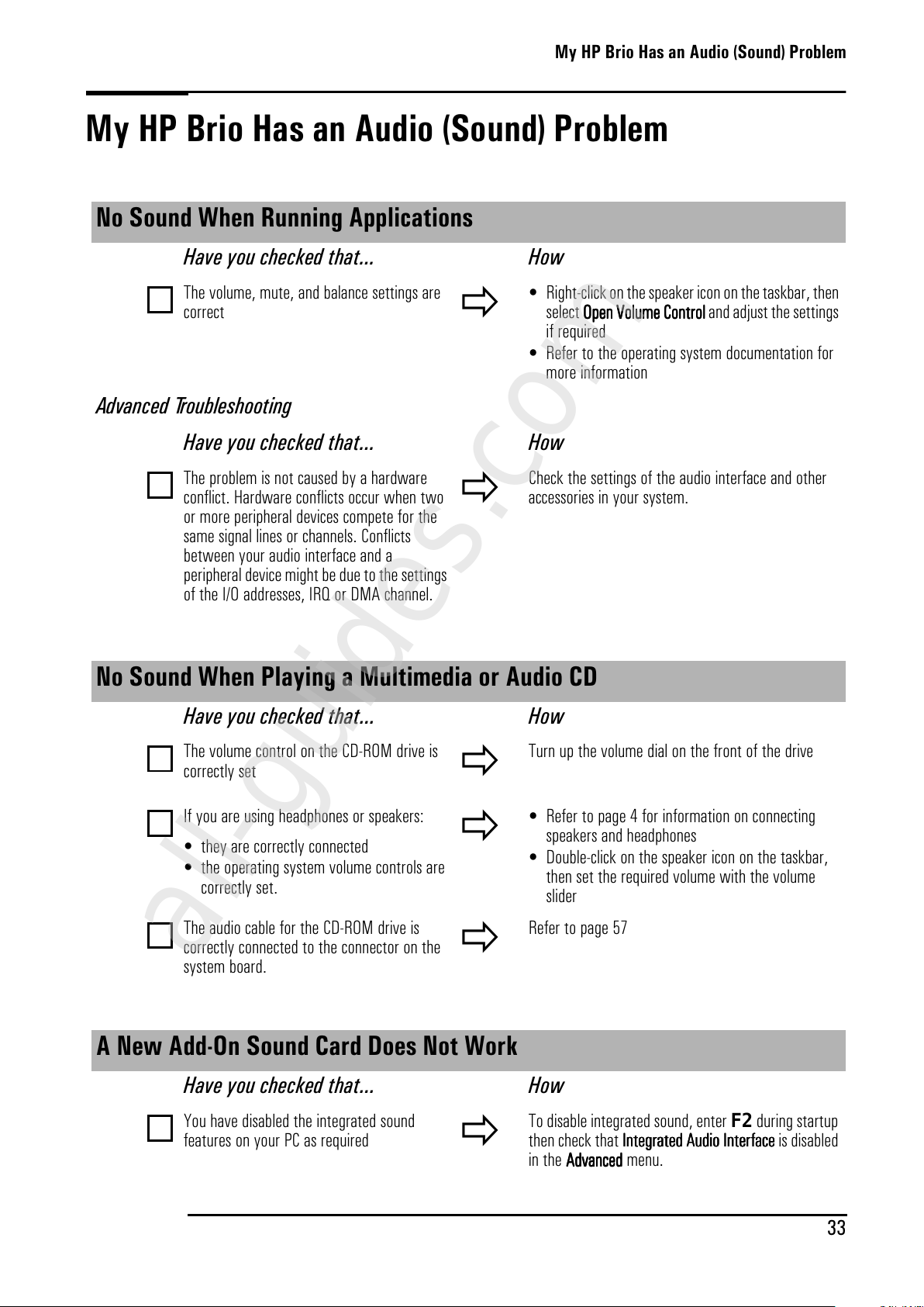
My HP Brio Has an Audio (Sound) Problem
33
My HP Brio Has an Audio (Sound) Problem
No Sound When Running Applications
Have you checked that...
How
The volume, mute, and balance settings are
correct
• Right-click on the speaker icon on the taskbar, then
select OOOOppppeeeennnnVVVVoooolllluuuummmmeeeeCCCCoooonnnntr
trtr
troooollll and adjust the settings
if required
• Refer to the operating system documentation for
more information
Advanced Troubleshooting
Have you checked that...
How
The problem is not caused by a hardware
conflict. Hardware conflicts occur when two
or more peripheral devices compete for the
same signal lines or channels. Conflicts
between your audio interface and a
peripheral device might be due to the settings
of the I/O addresses, IRQ or DMA channel.
Check the settings of the audio interface and other
accessories in your system.
No Sound When Playing a Multimedia or Audio CD
Have you checked that... How
The volume control on the CD-ROM drive is
correctly set
Turn up the volume dial on the front of the drive
If you are using headphones or speakers:
• they are correctly connected
• the operating system volume controls are
correctly set.
• Refer to page 4 for information on connecting
speakers and headphones
• Double-click on the speaker icon on the taskbar,
then set the required volume with the volume
slider
The audio cable for the CD-ROM drive is
correctly connected to the connector on the
system board.
Refer to page 57
A New Add-On Sound Card Does Not Work
Have you checked that... How
You have disabled the integrated sound
features on your PC as required
To disable integrated sound, enter F2during startup
then check that IIIInnnntttteeeeggggrrrraaaatttteeeeddddAAAAuuuuddddiiiiooooIIIInnnntttteeeerrrrffffaaaacccceeee is disabled
in the AAAAddddvvvvaaaannnncccceeeeddddmenu.
All manuals and user guides at all-guides.com
all-guides.com
Page 42
My HP Brio Has an Audio (Sound) Problem
34
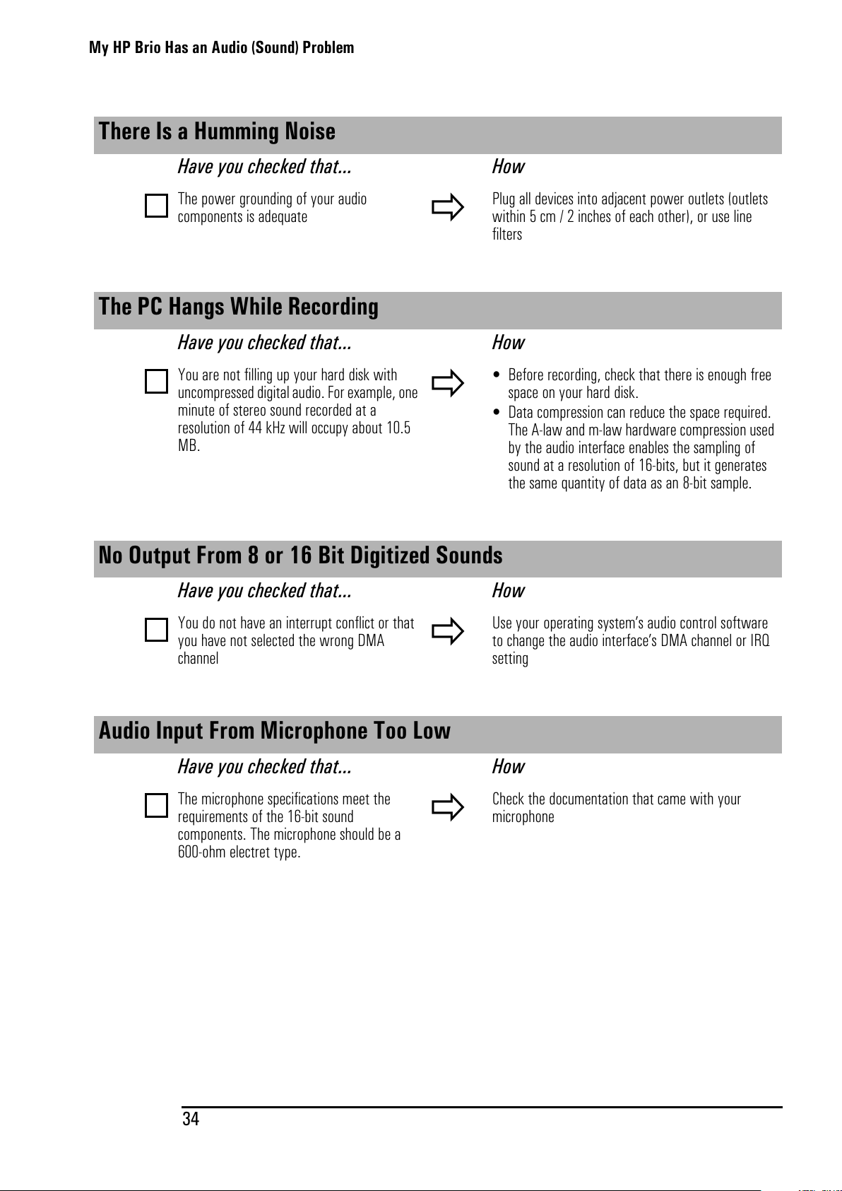
There Is a Humming Noise
Have you checked that... How
The power grounding of your audio
components is adequate
Plug all devices into adjacent power outlets (outlets
within 5 cm / 2 inches of each other), or use line
filters
The PC Hangs While Recording
Have you checked that... How
You are not filling up your hard disk with
uncompressed digital audio. For example, one
minute of stereo sound recorded at a
resolution of 44 kHz will occupy about 10.5
MB.
• Before recording, check that there is enough free
space on your hard disk.
• Data compression can reduce the space required.
The A-law and m-law hardware compression used
by the audio interface enables the sampling of
sound at a resolution of 16-bits, but it generates
thesamequantityofdataasan8-bitsample.
No Output From 8 or 16 Bit Digitized Sounds
Have you checked that... How
You do not have an interrupt conflict or that
you have not selected the wrong DMA
channel
Use your operating system’s audio control software
to change the audio interface’s DMA channel or IRQ
setting
Audio Input From Microphone Too Low
Have you checked that... How
The microphone specifications meet the
requirements of the 16-bit sound
components. The microphone should be a
600-ohm electret type.
Check the documentation that came with your
microphone
All manuals and user guides at all-guides.com
Page 43
My HP Brio Detects an Error at Startup
35
My HP Brio Detects an Error at Startup
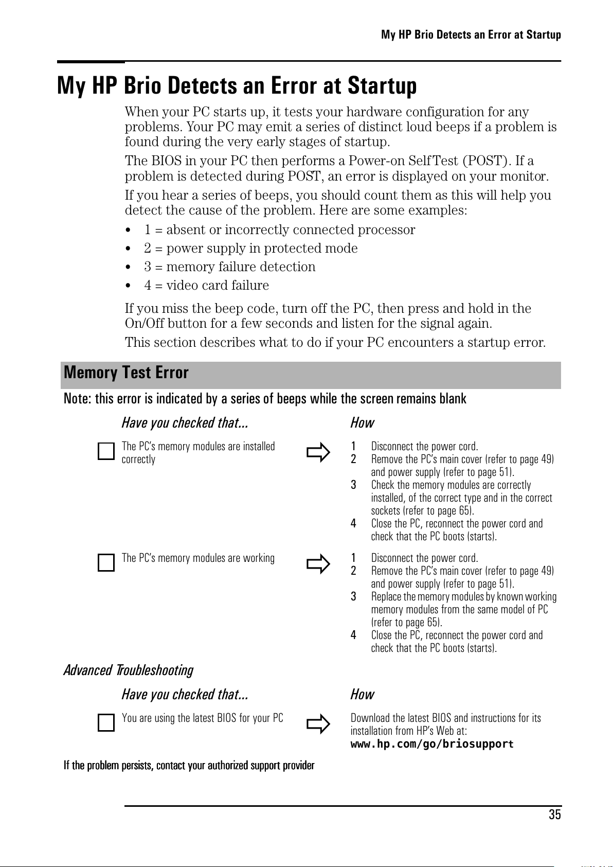
When your PC starts up, it tests your hardware configuration for any
problems. Your PC may emit a series of distinct loud beeps if a problem is
found during the very early stages of startup.
TheBIOSinyourPCthenperformsaPower-onSelfTest(POST).Ifa
problem is detected during POST, an error is displayed on your monitor.
If you hear a series of beeps, you should count them as this will help you
detect the cause of the problem. Here are some examples:
•
1 = absent or incorrectly connected processor
• 2 = power supply in protected mode
• 3 = memory failure detection
• 4 = video card failure
If you miss the beep code, turn off the PC, then press and hold in the
On/Off button for a few seconds and listen for the signal again.
This section describes what to do if your PC encounters a startup error.
Memory Test Error
Note: this error is indicated by a series of beeps while the screen remains blank
Have you checked that... How
The PC’s memory modules are installed
correctly
1
Disconnect the power cord.
2
Remove the PC’s main cover (refer to page 49)
and power supply (refer to page 51).
3
Check the memory modules are correctly
installed, of the correct type and in the correct
sockets (refer to page 65).
4
Close the PC, reconnect the power cord and
check that the PC boots (starts).
The PC’s memory modules are working
1
Disconnect the power cord.
2
Remove the PC’s main cover (refer to page 49)
and power supply (refer to page 51).
3
Replace the memorymodules byknown working
memory modules from the same model of PC
(refer to page 65).
4
Close the PC, reconnect the power cord and
check that the PC boots (starts).
Advanced Troubleshooting
Have you checked that... How
You are using the latest BIOS for your PC
Download the latest BIOS and instructions for its
installation from HP’s Web at:
www.hp.com/go/briosupport
IIIIfffftttthhhheeeepppprrrroooobbbblllleeeemmmmppppeeeerrrrssssiiiissssttttssss,,,,ccccon
onon
onttttaaaaccccttttyyyyoooouuuurrrraaaauuuutttthhhhoooorrrriiiizzzzeeeeddddssssuuuupppppo
popo
porrrrttttpppprrrroooovvvviiiiddddeeeerrrr
All manuals and user guides at all-guides.com
Page 44
My HP Brio Detects an Error at Startup
36
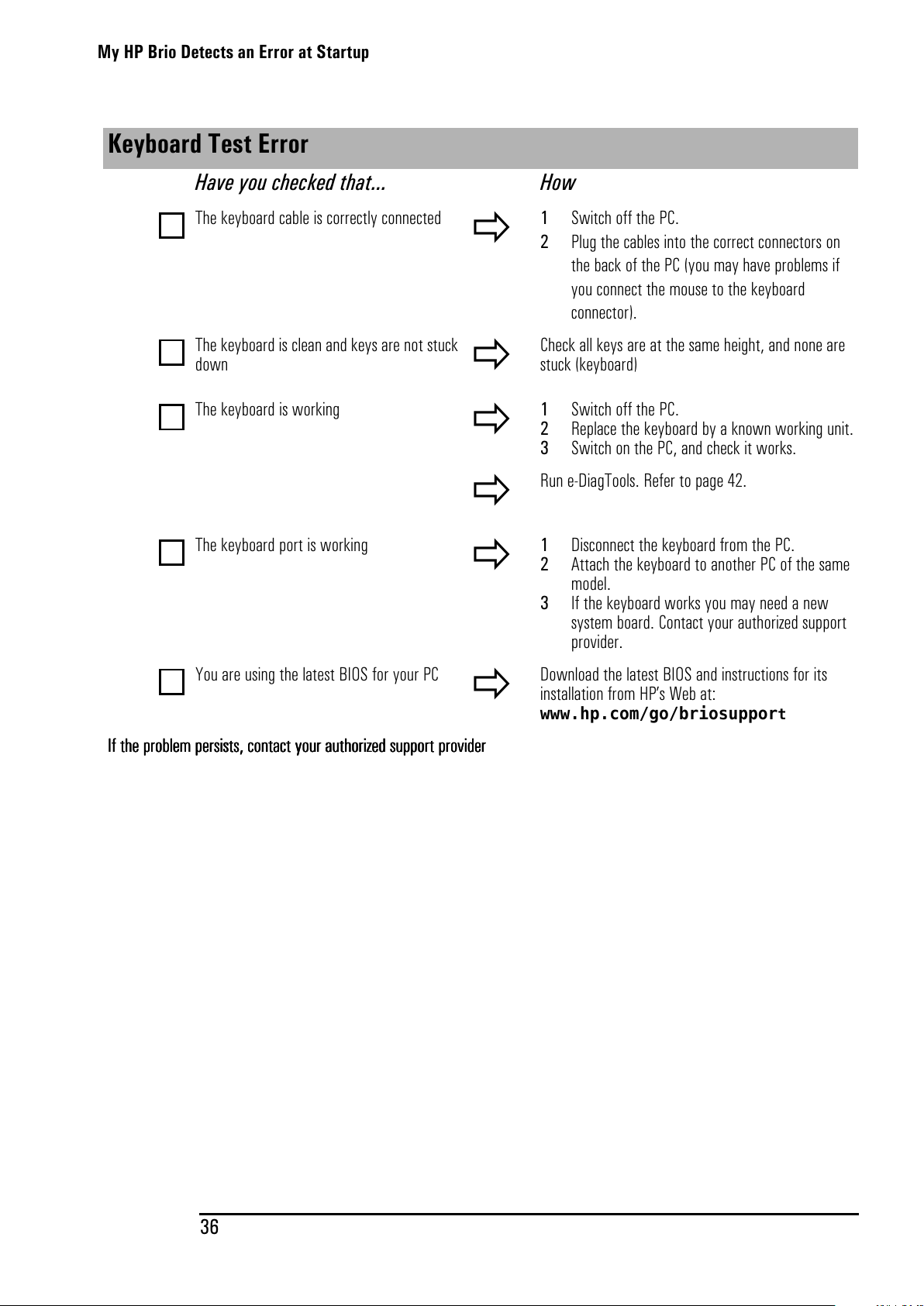
Keyboard Test Error
Have you checked that... How
The keyboard cable is correctly connected
1 Switch off the PC.
2 Plug the cables into the correct connectors on
the back of the PC (you may have problems if
you connect the mouse to the keyboard
connector).
The keyboard is clean and keys are not stuck
down
Check all keys are at the same height, and none are
stuck (keyboard)
The keyboard is working
1 Switch off the PC.
2 Replace the keyboard by a known working unit.
3 Switch on the PC, and check it works.
Run e-DiagTools. Refer to page 42.
The keyboard port is working
1 Disconnect the keyboard from the PC.
2 Attach the keyboard to another PC of the same
model.
3 If the keyboard works you may need a new
system board. Contact your authorized support
provider.
YouareusingthelatestBIOSforyourPC
Download the latest BIOS and instructions for its
installation from HP’s Web at:
www.hp.com/go/briosupport
IIIIfffftttthhhheeeepppprrrroooobbbblllleeeemmmmppppeeeerrrrssssiiiissssttttssss,,,,ccccon
onon
onttttaaaaccccttttyyyyoooouuuurrrraaaauuuuttttho
hoho
horrrriiiizzzzeeeeddddssssuuuuppppppppoooort
rtrt
rt pppprrrroooovvvviiiiddddeeeerrrr
All manuals and user guides at all-guides.com
Page 45
My HP Brio Detects an Error at Startup
37
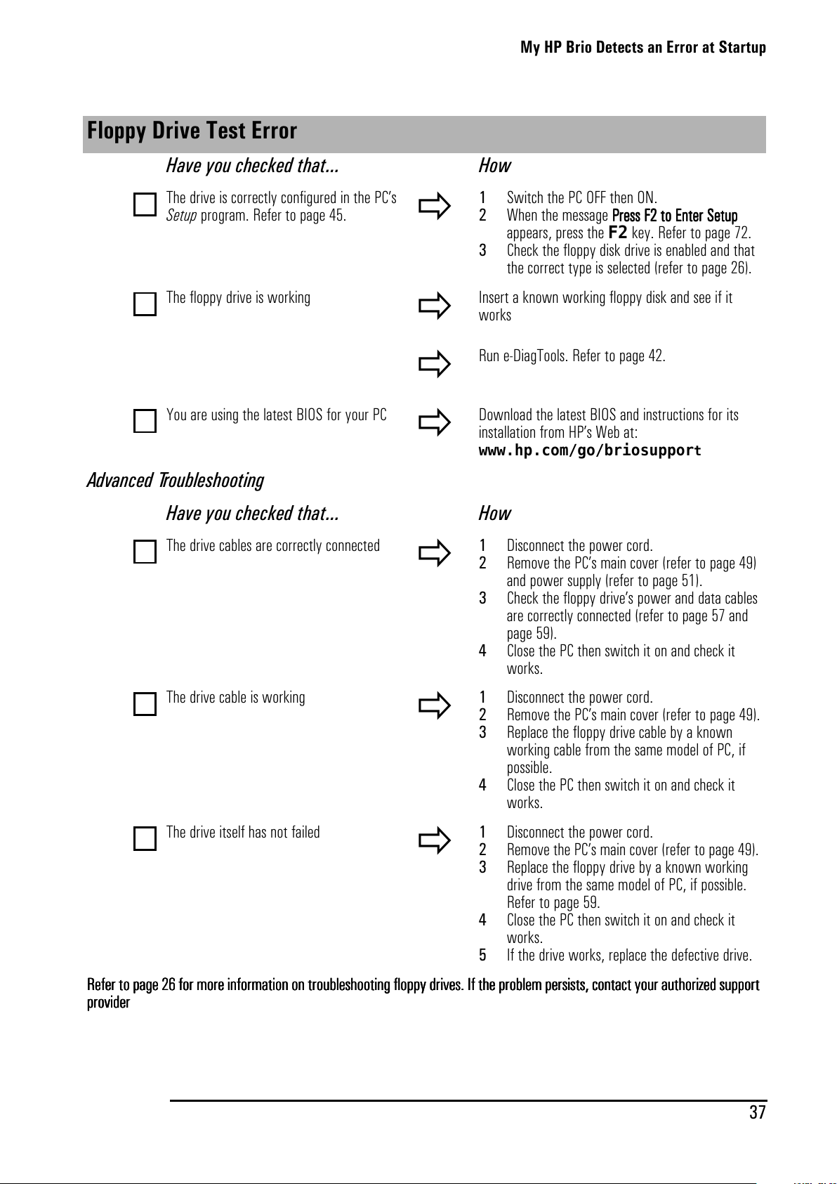
Floppy Drive Test Error
Have you checked that... How
The drive is correctly configured in the PC’s
Setup program. Refer to page 45.
1 Switch the PC OFF then ON.
2 When the message PPPPrrrreeeess
ssss
ss FFFF2222ttttooooEEEEnnnntttteeeerrrrSSSSeeeettttuuuupppp
appears, press the F2 key. Refer to page 72.
3 Check the floppy disk drive is enabled and that
the correct type is selected (refer to page 26).
The floppy drive is working
Insert a known working floppy disk and see if it
works
Run e-DiagTools. Refer to page 42.
You are using the latest BIOS for your PC
Download the latest BIOS and instructions for its
installation from HP’s Web at:
www.hp.com/go/briosuppor
t
Advanced Troubleshooting
Have you checked that... How
The drive cables are correctly connected
1 Disconnect the power cord.
2 Remove the PC’s main cover (refer to page 49)
and power supply (refer to page 51).
3 Check the floppy drive’s power and data cables
are correctly connected (refer to page 57 and
page 59).
4 Close the PC then switch it on and check it
works.
The drive cable is working
1 Disconnect the power cord.
2 Remove the PC’s main cover (refer to page 49).
3 Replace the floppy drive cable by a known
working cable from the same model of PC, if
possible.
4 Close the PC then switch it on and check it
works.
The drive itself has not failed
1 Disconnect the power cord.
2 Remove the PC’s main cover (refer to page 49).
3 Replace the floppy drive by a known working
drive from the same model of PC, if possible.
Refer to page 59.
4 Close the PC then switch it on and check it
works.
5 If the drive works, replace the defective drive.
RRRReeeeffffeeeerrrrtttto p
opop
opaaaaggggeeee26
2626
26 ffffoooorrrrmmmmoooorrrreeeeiiiinnnnffffoooorrrrmmmmaaaattttiiiioooon o
nono
nonnnntr
trtr
troooouuuubbbblllleeeesssshhhhoooooooottttiiiinnnnggggfffflllloooopp
pppp
ppyyyyddddrrrriiiivvvveeeessss....IIIIfffftttthhhheeeepppprrrroooobbbblllleeeemmmmppppeeeerrrrssssiiiissssttttssss,,,,ccccoooonnnnttttaaaaccccttttyyyyoooouuuurrrraaaauuuuttttho
hoho
horrrriiiizzzzeeeeddddssssup
upup
upppppoooort
rtrt
rt
pppprrrroooovvvviiiiddddeeeerrrr
All manuals and user guides at all-guides.com
Page 46
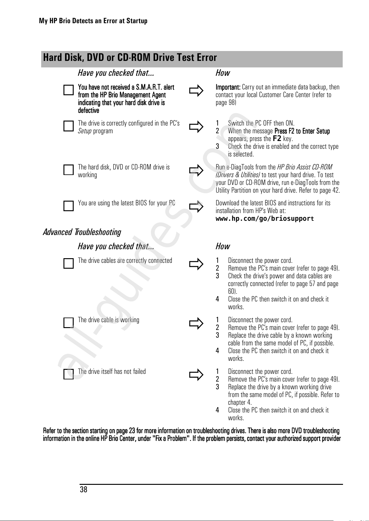
My HP Brio Detects an Error at Startup
38
Hard Disk, DVD or CD-ROM Drive Test Error
Have you checked that... How
YYYYoooouuuuhhhhaaaavvvveeeennnnoooottttrrrreeeecccceeeeiiiivvvveeeeddddaaaaSSSS....MMMM....AAAA....RRRR....TTTT....aaaalllleeeert
rtrt
rt
ffffrrrroooommmmtttthhhheeeeHHHHPPPPBBBBrrrriiiiooooMMMMaaaannnnaaaaggggeeeemmmmeeeennnnttttAAAAggggeeeennnntttt
iiiinnnnddddiiiiccccaaaattttiiiinnnnggggtttthhhhaaaattttyyyyoooouuuurrrrhhhhaaaarrrrddddddddiiiisssskkkkddddrrrriiiivvvveeeeiiiissss
ddddeeeeffffeeeeccccttttiiiivvvveeee
IIIImmmmppppoooort
rtrt
rtaaaannnntttt:::: Carry out an immediate data backup, then
contact your local Customer Care Center (refer to
page 98)
The drive is correctly configured in the PC’s
Setup program
1 Switch the PC OFF then ON.
2 When the message PPPPrrrreeeess
ssss
ss FFFF2222ttttooooEEEEnnnntttteeeerrrrSSSSeeeettttup
upup
up
appears, press the F2 key.
3 Check the drive is enabled and the correct type
is selected.
The hard disk, DVD or CD-ROM drive is
working
Run e-DiagTools from the HP Brio Assist CD-ROM
(Drivers & Utilities) to test your hard drive. To test
your DVD or CD-ROM drive, run e-DiagTools from the
Utility Partition on your hard drive. Refer to page 42.
YouareusingthelatestBIOSforyourPC
Download the latest BIOS and instructions for its
installation from HP’s Web at:
www.hp.com/go/briosuppor
t
Advanced Troubleshooting
Have you checked that... How
The drive cables are correctly connected
1 Disconnect the power cord.
2 Remove the PC’s main cover (refer to page 49).
3 Check the drive’s power and data cables are
correctly connected (refer to page 57 and page
60).
4 Close the PC then switch it on and check it
works.
The drive cable is working
1 Disconnect the power cord.
2 Remove the PC’s main cover (refer to page 49).
3 Replace the drive cable by a known working
cable from the same model of PC, if possible.
4 Close the PC then switch it on and check it
works.
The drive itself has not failed
1 Disconnect the power cord.
2 Remove the PC’s main cover (refer to page 49).
3 Replace the drive by a known working drive
from the same model of PC, if possible. Refer to
chapter 4.
4 Close the PC then switch it on and check it
works.
RRRReeeeffffeeeerrrrttttooootttthhhheeeesssseeeeccccttttiiiioooonnnnssssttttaaaart
rtrt
rtiiiinnnnggggoooon p
npnp
npaaaaggggeeee23
2323
23 ffffoooorrrrmmmmoooorrrreeeeiiiinnnnffffoooorrrrmmmmaaaattttiiiion o
on oon o
on onnnntr
trtr
trooooub
ubub
ublllleeeesssshhhhoooooooottttiiiinnnnggggddddrrrriiiivvvveeeessss....TTTThhhheeeerrrreeeeiiiissssaaaallllssssoooommmmoooorrrreeeeDDDDVVVVDDDDtr
trtr
trooooub
ubub
ublllleeeesssshhhhoooooooottttiiiinnnngggg
iiiinnnnffffoooorrrrmmmmaaaattttiiiion
onon
on iiiinnnntttthhhheeeeoooonnnnli
lili
linnnneeeeHHHHPPPPBBBBrrrriiiiooooCCCCeeeennnntttteeeerrrr,,,,uuuunnnnddddeeeerrrr""""FFFFiiiixxxxaaaaPPPPrrrroooobbbblllleeeemmmm""""....IIIIfffftttthhhheeeepppprrrroooobbbblllleeeemmmmppppeeeerrrrssssiiiissssttttssss,,,,ccccoooonnnnttttaaaaccccttttyyyyou
ouou
ourrrraaaauuuutttthhhhoooorrrriiiizzzzeeeeddddssssup
upup
upppppoooort
rtrt
rt pppprrrroooovvvviiiiddddeeeerrrr
All manuals and user guides at all-guides.com
all-guides.com
Page 47
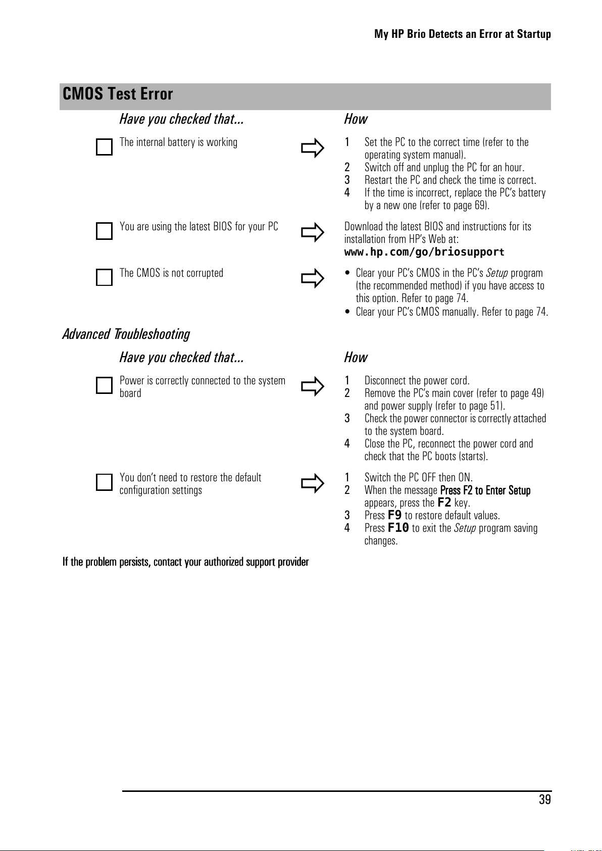
My HP Brio Detects an Error at Startup
39
CMOS Test Error
Have you checked that... How
The internal battery is working
1 Set the PC to the correct time (refer to the
operating system manual).
2 Switch off and unplug the PC for an hour.
3 Restart the PC and check the time is correct.
4 If the time is incorrect, replace the PC’s battery
by a new one (refer to page 69).
You are using the latest BIOS for your PC
Download the latest BIOS and instructions for its
installation from HP’s Web at:
www.hp.com/go/briosupport
The CMOS is not corrupted
• Clear your PC’s CMOS in the PC’s Setup program
(the recommended method) if you have access to
this option. Refer to page 74.
• Clear your PC’s CMOS manually. Refer to page 74.
Advanced Troubleshooting
Have you checked that... How
Power is correctly connected to the system
board
1 Disconnect the power cord.
2 Remove the PC’s main cover (refer to page 49)
and power supply (refer to page 51).
3 Check the power connector is correctly attached
to the system board.
4 Close the PC, reconnect the power cord and
check that the PC boots (starts).
You don’t need to restore the default
configuration settings
1 Switch the PC OFF then ON.
2 When the message PPPPrrrreeeess
ssss
ss FFFF2222ttttooooEEEEnnnntttteeeerrrrSSSSeeeettttuuuupppp
appears, press the F2 key.
3 Press F9 to restore default values.
4 Press F10 to exit the Setup program saving
changes.
IIIIfffftttthhhheeeepppprrrroooobbbblllleeeemmmmppppeeeerrrrssssiiiissssttttssss,,,,ccccon
onon
onttttaaaaccccttttyyyyoooouuuurrrraaaauuuutttthhhhoooorrrriiiizzzzeeeeddddssssuuuupppppo
popo
porrrrttttpppprrrroooovvvviiiiddddeeeerrrr
All manuals and user guides at all-guides.com
Page 48
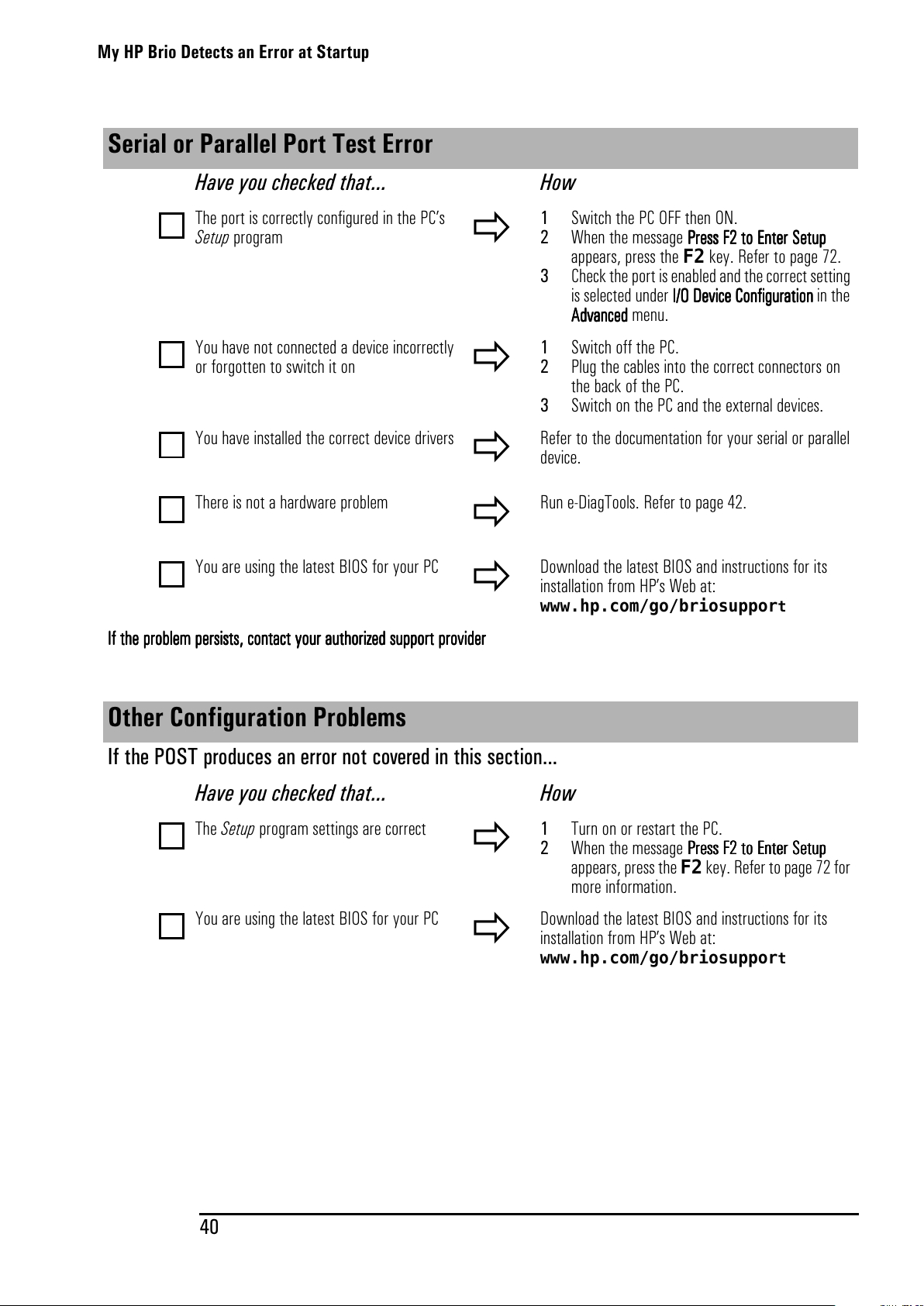
My HP Brio Detects an Error at Startup
40
Serial or Parallel Port Test Error
Have you checked that... How
The port is correctly configured in the PC’s
Setup program
1 Switch the PC OFF then ON.
2 When the message PPPPrrrreeeess
ssss
ss FFFF2222ttttooooEEEEnnnntttteeeerrrrSSSSeeeettttup
upup
up
appears, press the F2 key. Refer to page 72.
3 Check the port is enabled and the correct setting
is selected under IIII////O D
ODOD
ODeeeevvvviiiicccceeeeCCCCoooonnnnffffiiiigu
gugu
gurrrraaaattttiiiioooonnnninthe
AAAAddddvvvvaaaannnncccceeeeddddmenu.
You have not connected a device incorrectly
or forgotten to switch it on
1 Switch off the PC.
2 Plug the cables into the correct connectors on
the back of the PC.
3 Switch on the PC and the external devices.
You have installed the correct device drivers
Refer to the documentation for your serial or parallel
device.
There is not a hardware problem
Run e-DiagTools. Refer to page 42.
YouareusingthelatestBIOSforyourPC
Download the latest BIOS and instructions for its
installation from HP’s Web at:
www.hp.com/go/briosuppor
t
IIIIfffftttthhhheeeepppprrrroooobbbblllleeeemmmmppppeeeerrrrssssiiiissssttttssss,,,,ccccon
onon
onttttaaaaccccttttyyyyoooouuuurrrraaaauuuuttttho
hoho
horrrriiiizzzzeeeeddddssssuuuuppppppppoooort
rtrt
rt pppprrrroooovvvviiiiddddeeeerrrr
Other Configuration Problems
If the POST produces an error not covered in this section...
Have you checked that... How
The Setup program settings are correct
1 Turn on or restart the PC.
2 When the message PPPPrrrreeeess
ssss
ss FFFF2222ttttooooEEEEnnnntttteeeerrrrSSSSeeeettttup
upup
up
appears, press the F2key. Refer to page 72 for
more information.
YouareusingthelatestBIOSforyourPC
Download the latest BIOS and instructions for its
installation from HP’s Web at:
www.hp.com/go/briosuppor
t
All manuals and user guides at all-guides.com
Page 49
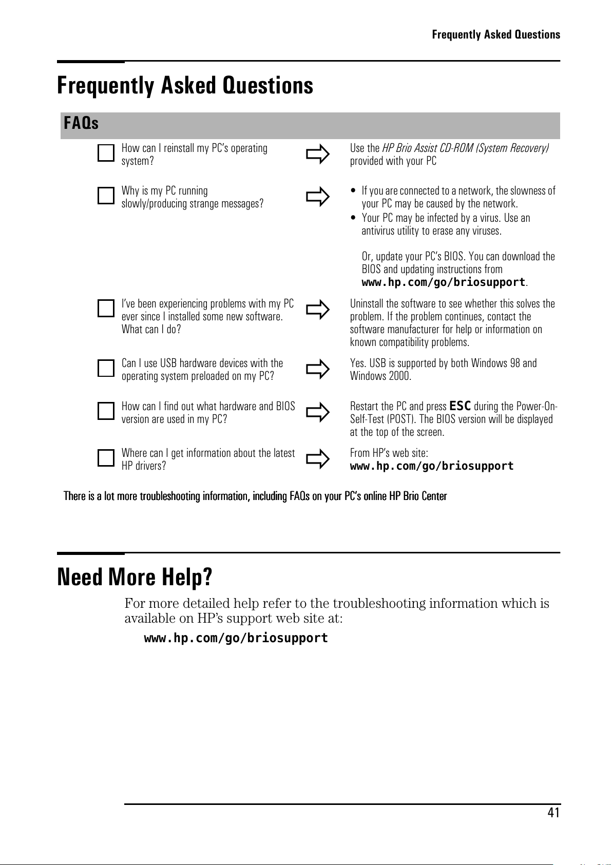
Frequently Asked Questions
41
Frequently Asked Questions
Need More Help?
For more detailed help refer to the troubleshooting information which is
available on HP’s support web site at:
www.hp.com/go/briosupport
FAQs
How can I reinstall my PC’s operating
system?
Use the HP Brio Assist CD-ROM (System Recovery)
provided with your PC
Why is my PC running
slowly/producing strange messages?
• If you are connected to a network, the slowness of
yourPCmaybecausedbythenetwork.
• YourPCmaybeinfectedbyavirus.Usean
antivirus utility to erase any viruses.
Or, update your PC’s BIOS. You can download the
BIOS and updating instructions from
www.hp.com/go/briosupport
.
I’ve been experiencing problems with my PC
ever since I installed some new software.
What can I do?
Uninstall the software to see whether this solves the
problem. If the problem continues, contact the
software manufacturer for help or information on
known compatibility problems.
Can I use USB hardware devices with the
operating system preloaded on my PC?
Yes. USB is supported by both Windows 98 and
Windows 2000.
How can I find out what hardware and BIOS
version are used in my PC?
Restart the PC and press ESC during the Power-On-
Self-Test (POST). The BIOS version will be displayed
at the top of the screen.
Where can I get information about the latest
HP drivers?
From HP’s web site:
www.hp.com/go/briosupport
TTTThhhheeeerrrreeeeiiiissssaaaalllloooottttmmmmoooorrrreeeetr
trtr
troooouuuubbbblllleeeesssshhhhoooooooottttiiiinnnnggggiiiinnnnffffoooorrrrmmmmaaaattttiiiioooonnnn,,,,iiiinnnnccccllllud
udud
udiiiinnnnggggFFFFAAAAQQQQssssoooonnnnyyyyoooouuuurrrrPC
PCPC
PC’’’’sssson
onon
onli
lili
linnnneeeeHHHHPPPPBBBBrrrriiiiooooCCCCeeeennnntttteeeerrrr
All manuals and user guides at all-guides.com
Page 50
HP Hardware Diagnostics (e-DiagTools)
42
HP Hardware Diagnostics (e-DiagTools)
Note
HP strongly recommends you use e-DiagTools. It provides the most effective way of solving
most hardware problems. It can also help you distinguish between a hardware and a software
problem.
What Is e-DiagTools For?
With e-DiagTools, you can:
• check the configuration of your PC and see whether it is functioning
correctly
• diagnose hardware-related problems
•
provide precise information to support personnel so that they can solve
your problems quickly and efficiently.
How Do I Run e-DiagTools?
Youcanrune-DiagToolsfrom:
• The Utility Partition on your PC’s hard drive.
To run diagnostics from the hard drive, restart the PC and press F10
when the message Press F10 to start hardware
diagnostics...or any other key to proceed appears on
screen.
•
Your PC’s HP Brio Assist CD-ROM - Drivers & Utilities.Referto“HP
Brio Assist CD-ROM” below.
All manuals and user guides at all-guides.com
Page 51
HP Brio Assist CD-ROM
43
HP Brio Assist CD-ROM
Your PC comes with two HP Brio Assist CD-ROMs (Windows 98 version)
or three (Windows 2000 version):
• HP Brio Assist CD-ROM - System Recovery (1 or 2 CDs)
•
HP Brio Assist CD-ROM - Drivers & Utilities (1 CD)
HP Brio Assist CD-ROM - System Recovery
Use this CD-ROM to:
• perform a full system recovery
•
replace Windows 2000 with Windows NT 4.0 (feature available in some
countries only)
HP Brio Assist CD-ROM - Drivers & Utilities
Use this CD-ROM to:
• reinstall individual device drivers or utilities
•
run e-DiagTools hardware diagnostics.
Using the HP Brio Assist CD-ROMs
To use the HP Brio Assist CD-ROMs, you must either:
• boot the PC from the CD-ROM
• browse the CD-ROM while the PC is running.
Note
If the PC does not boot from the HP Brio Assist CD-ROM - System Recovery, you must change
the order of devices from which your PC tries to start up. To do so, restart your PC and press
F2
when prompted to enter the HP Setup program. Change the
Boot Device Priority
in the
Setup program
Boot
menu so that
ATAPI CD-ROM Drive
appears before
Hard Drive
(refer to
“Support and Information Services” on page 45).
Performing a Full System Recovery or Alternative OS Installation
You can use the HP Brio Assist CD-ROM - System Recovery to recover
the PC’s factory supplied configuration by restoring the operating system
(OS), drivers and HP supplied applications. This will return the PC’s
software configuration to a state similar to when the PC was originally
shipped.
In some countries on Windows 2000 models, you can also replace the
preloaded Windows 2000 operating system with Windows NT 4.0.
All manuals and user guides at all-guides.com
all-guides.com
Page 52
HP Brio Assist CD-ROM
44
Note Restoring the original factory configuration or downgrading will completely erase the main hard
drive partition. It is highly recommended to (a) back up all your data before proceeding, (b)
remove all devices you have added, (c) update your PC’s BIOS (refer to page 76) and (d) have
driver software to hand for any add-on hardware. The whole process normally takes about half
an hour.
If you intend to replace your Windows 2000 operating system with Windows NT 4.0, you
should check that you will still be able to use your system as intended. For example, Windows
NT 4.0 does not support Power Management or USB. If you need to use a USB device, then you
should not perform this operation.
1 Insert the HP Brio Assist CD-ROM - System Recovery in your CD-ROM
drive and restart your PC.
2 From the main menu, select the operating system you want to install.
3 Follow the onscreen instructions.
When the copy operation is complete a message will appear. Remove
the CD-ROM and restart the PC.
4 Reinstall drivers for any devices that were not part of your PC’s original
configuration. All data files and software applications that were not part
of your PC’s original configuration PC must also be restored.
Manually Reinstalling Drivers
1 Insert the HP Brio Assist CD-ROM - Drivers & Utilities in the CD-ROM
drive while your operating system is running.
2 Using Windows Explorer, select the driver(s) you need to reinstall.
3 Follow the installation instructions contained in the README file
accompanying the driver.
Running HP e-DiagTools
1 Insert the HP Brio Assist CD-ROM - Drivers & Utilities in the CD-ROM
drive and restart the PC.
2 In the menu that appears, select Run Hardware Diagnostics.
3 Follow the onscreen instructions in the e-DiagTools screen that
appears.
All manuals and user guides at all-guides.com
Page 53
Support and Information Services
Support and Information Services
You can learn more about HP service and support from the support Web
site:
www.hp.com/go/briosupport.
Information on Your Warranty and Customer Care Centers
Details about the warranty that comes with your HP Brio PC and how to
contact HP Customer Care Centers are available on page 86 and page 98
respectively.
Collecting Information on Your PC Before Contacting HP Support
Take a piece of paper and note down some of the information mentioned
below. This will help HP support deal with your problem quickly and
efficiently:
Model number See label on the right side of your PC.
Serial number See label on the right side of your PC.
RAM
• Number of megabytes installed
•
The amount of RAM is displayed on the Summary Screen, accessed by pressing
Escduring start-up or in the Setup program, accessed by pressingF2 during
start-up.
Write down a brief description of the problem
Frequency How often has the problem occurred?
Run OK? How long has the PC been running normally?
Recent changes to the PC Have there been any recent changes made to the PC?
Any e-DiagTools errors? Run e-DiagTools. Refer to page 42.
Which BIOS version is used? The BIOS version is displayed on the Summary Screen, accessed by pressing Esc
during start-up or in the Setup program, accessed by pressing F2 during start-up.
Any BIOS parameter changes? Did the problem occur after changes were made to the BIOS using the Setup
program?
Are you using the original operating system
software that came preloaded on your PC?
What is the operating system version?
If no, what is the operating system version? Select Settings ➪ Control Panel from the Start menu, then click on the System
icon. The operating system version is displayed under System.
Any operating system-generated error messages Please note down exact text of error message.
Any errors during boot (Power-On Self Test).
This test checks all installed components.
Any POST errors will be displayed on your monitor screen or signalled by beep
codes. If you hear any beep codes, you should count them.
All manuals and user guides at all-guides.com
Page 54
Support and Information Services
46
All manuals and user guides at all-guides.com
Page 55
4
Status
Upgrading and Replacing HP Brio
Hardware
This chapter describes how to:
• upgrade hardware components
• replace faulty components
If you want to find out about available accessories for your PC, refer to the
HP accessories Web site at: www.hp.com/go/pcaccessories
Important - Before You Start ......................................................... page 48
Inside the Computer....................................................................... page 48
Accessing Internal Components ..................................................... page 49
Replacing the System Board .......................................................... page 55
Cables and Connectors in Your PC ................................................. page 57
Replacing a Processor.................................................................... page 58
Replacing the Floppy Drive............................................................. page 59
Replacing the Hard Drive ............................................................... page 60
Installing an Expansion Bay Drive................................................... page 62
Installing a Memory Module........................................................... page 65
Installing an Expansion Card .......................................................... page 66
Replacing the Power Supply Unit ................................................... page 67
Replacing the Battery.................................................................... page 69
All manuals and user guides at all-guides.com
Page 56
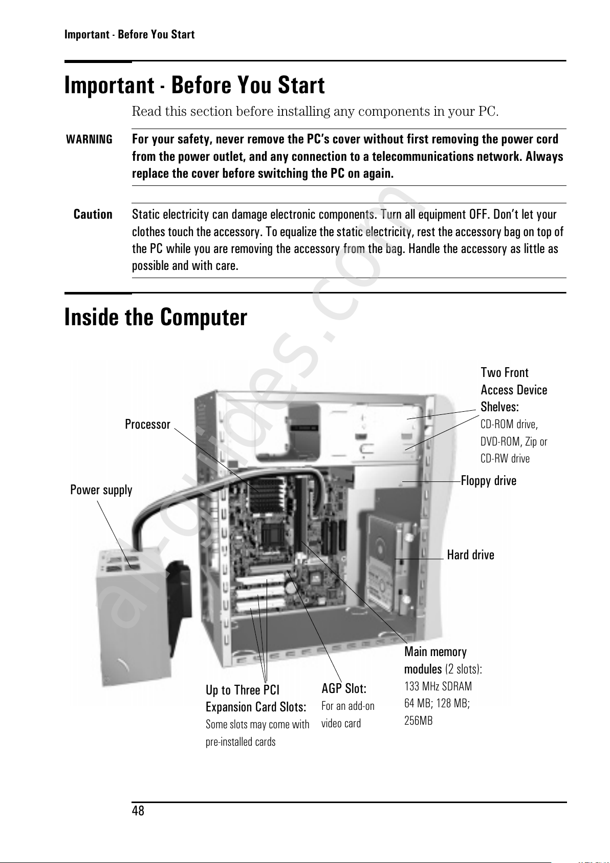
Important - Before You Start
48
Important - Before You Start
Read this section before installing any components in your PC.
WARNING
For your safety, never remove the PC’s cover without first removing the power cord
from the power outlet, and any connection to a telecommunications network. Always
replace the cover before switching the PC on again.
Caution
Static electricity can damage electronic components. Turn all equipment OFF. Don’t let your
clothes touch the accessory. To equalize the static electricity, rest the accessory bag on top of
the PC while you are removing the accessory from the bag. Handle the accessory as little as
possible and with care.
Inside the Computer
Floppy drive
Hard drive
Power supply
Up to Three PCI
Expansion Card Slots:
Some slots may come with
pre-installed cards
Main memory
modules
(2 slots):
133 MHz SDRAM
64 MB; 128 MB;
256MB
Processor
Two Front
Access Device
Shelves:
CD-ROM drive,
DVD-ROM, Zip or
CD-RW drive
AGP Slot:
For an add-on
video card
All manuals and user guides at all-guides.com
all-guides.com
Page 57
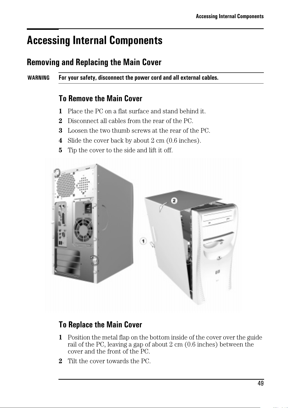
Accessing Internal Components
49
Accessing Internal Components
Removing and Replacing the Main Cover
WARNING
For your safety, disconnect the power cord and all external cables.
To Remove the Main Cover
1 Place the PC on a flat surface and stand behind it.
2 Disconnect all cables from the rear of the PC.
3 Loosen the two thumb screws at the rear of the PC.
4 Slide the cover back by about 2 cm (0.6 inches).
5 Tip the cover to the side and lift it off.
To Replace the Main Cover
1 Position the metal flap on the bottom inside of the cover over the guide
rail of the PC, leaving a gap of about 2 cm (0.6 inches) between the
cover and the front of the PC.
2 Tilt the cover towards the PC.
All manuals and user guides at all-guides.com
Page 58
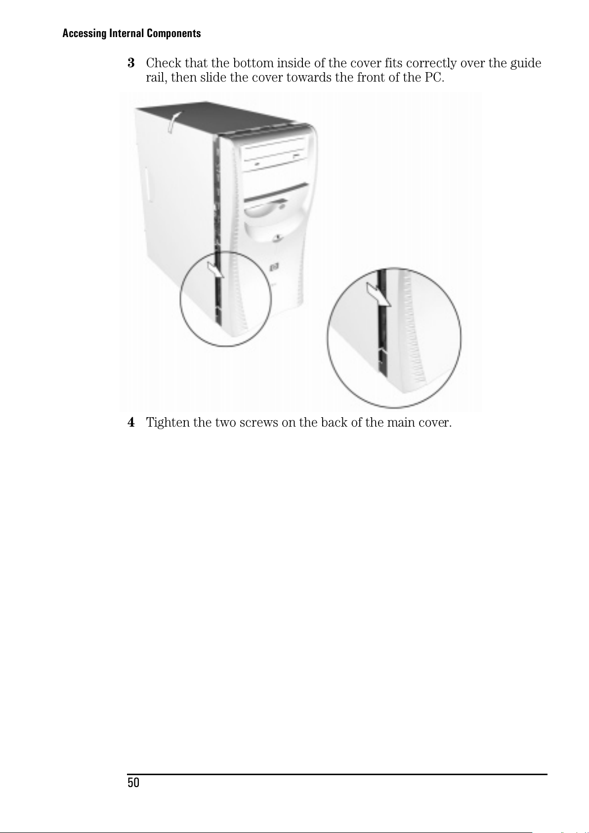
Accessing Internal Components
50
3 Check that the bottom inside of the cover fits correctly over the guide
rail, then slide the cover towards the front of the PC.
4 Tighten the two screws on the back of the main cover.
All manuals and user guides at all-guides.com
Page 59
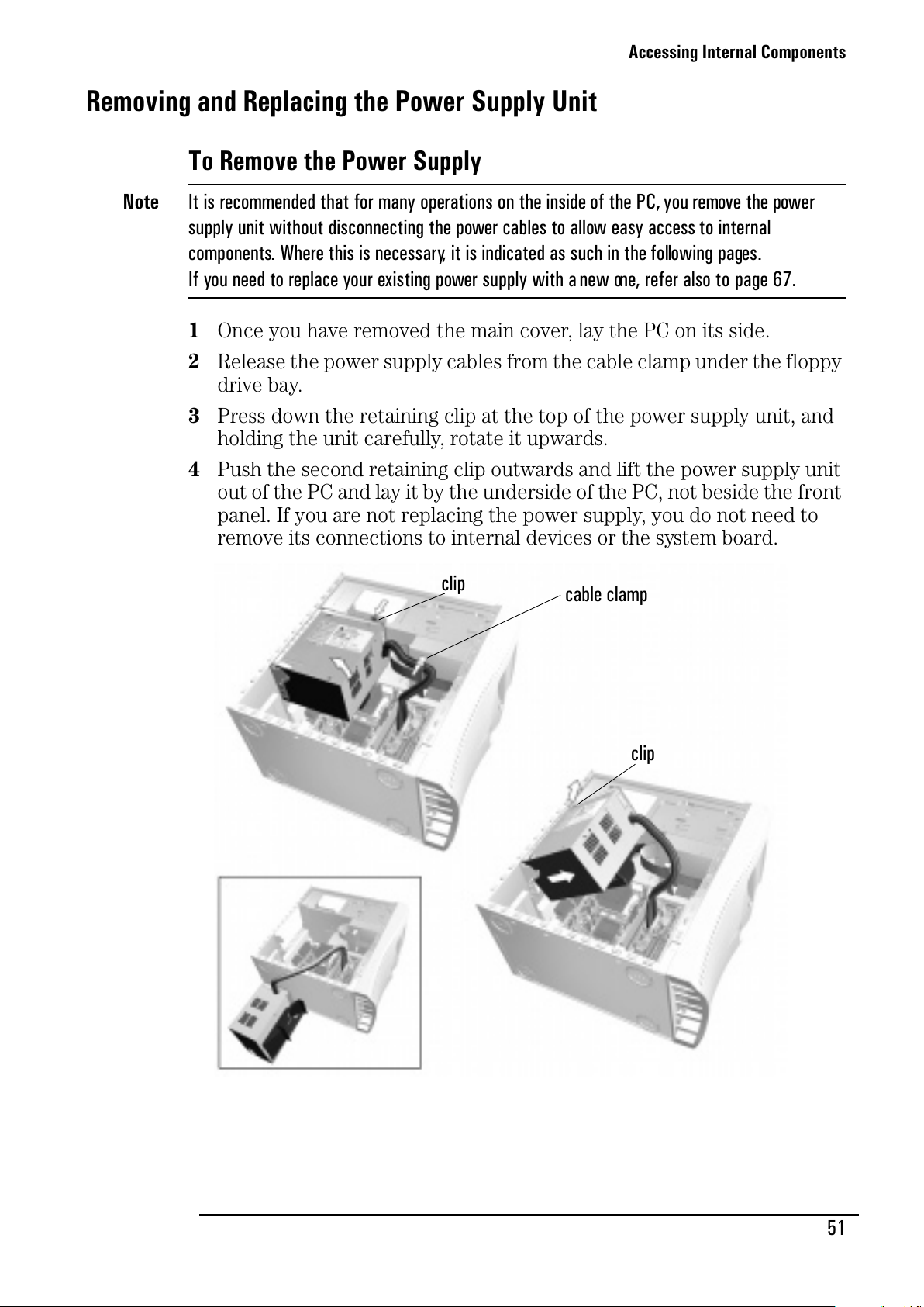
Accessing Internal Components
51
Removing and Replacing the Power Supply Unit
To Remove the Power Supply
Note
It is recommended that for many operations on the inside of the PC, you remove the power
supply unit without disconnecting the power cables to allow easy access to internal
components. Where this is necessary, it is indicated as such in the following pages.
Ifyouneedtoreplaceyourexistingpowersupplywithanewone,referalsotopage67.
1 Once you have removed the main cover, lay the PC on its side.
2 Release the power supply cables from the cable clamp under the floppy
drive bay.
3 Press down the retaining clip at the top of the power supply unit, and
holding the unit carefully, rotate it upwards.
4 Push the second retaining clip outwards and lift the power supply unit
out of the PC and lay it by the underside of the PC, not beside the front
panel. If you are not replacing the power supply, you do not need to
remove its connections to internal devices or the system board.
cable clamp
clip
clip
All manuals and user guides at all-guides.com
Page 60
Accessing Internal Components
52
To Replace the Power Supply
Caution
Ensure that you do not trap or crush any internal cables when replacing the power supply.
1 Insert the protruding pins at the back of the unit in the guiding grooves.
2 Rotate the power supply back into place, making sure that you are not
trapping or crushing any cables on the underside of the unit (especially
if your power supply has an airflow guide fitted).
3 Snap the unit back into place.
All manuals and user guides at all-guides.com
Page 61
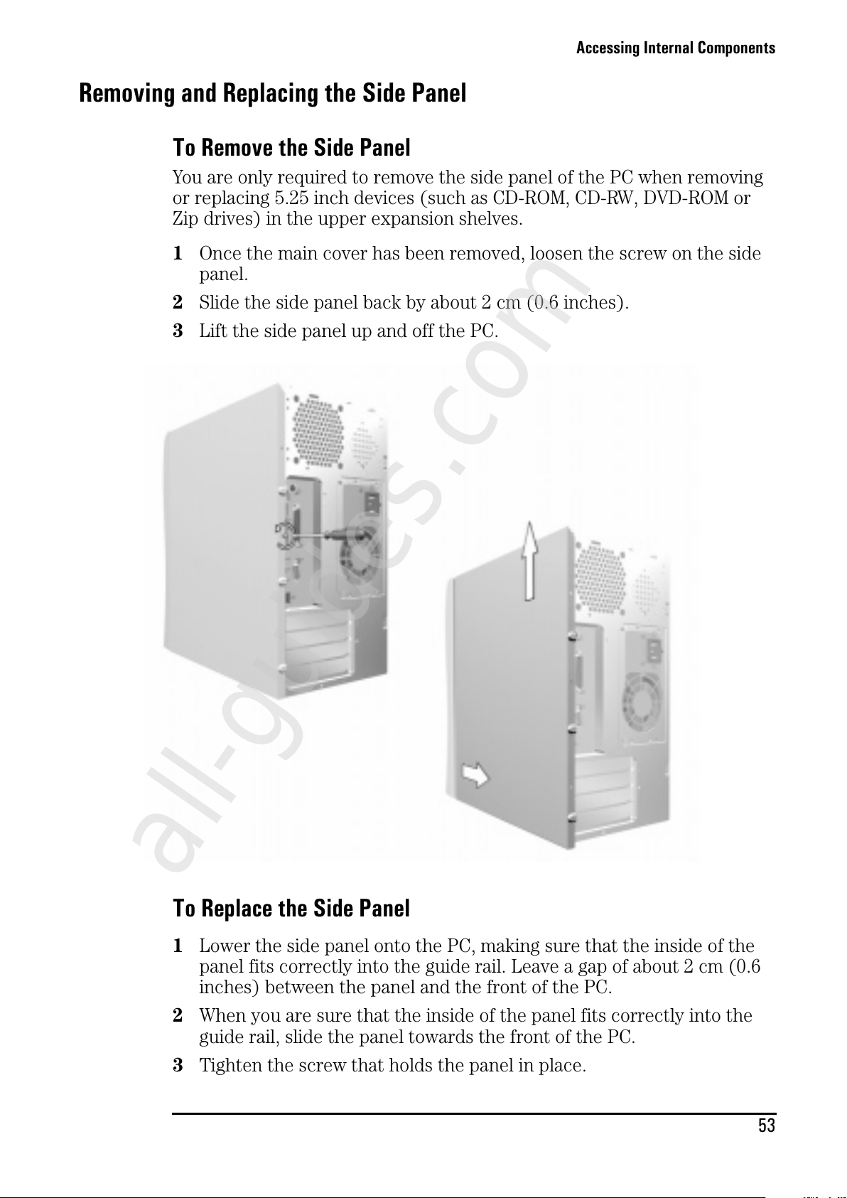
Accessing Internal Components
53
Removing and Replacing the Side Panel
To Remove the Side Panel
You are only required to remove the side panel of the PC when removing
or replacing 5.25 inch devices (such as CD-ROM, CD-RW, DVD-ROM or
Zip drives) in the upper expansion shelves.
1 Once the main cover has been removed, loosen the screw on the side
panel.
2 Slide the side panel back by about 2 cm (0.6 inches).
3 LiftthesidepanelupandoffthePC.
To Replace the Side Panel
1 Lower the side panel onto the PC, making sure that the inside of the
panel fits correctly into the guide rail. Leave a gap of about 2 cm (0.6
inches) between the panel and the front of the PC.
2 When you are sure that the inside of the panel fits correctly into the
guide rail, slide the panel towards the front of the PC.
3 Tighten the screw that holds the panel in place.
All manuals and user guides at all-guides.com
all-guides.com
Page 62
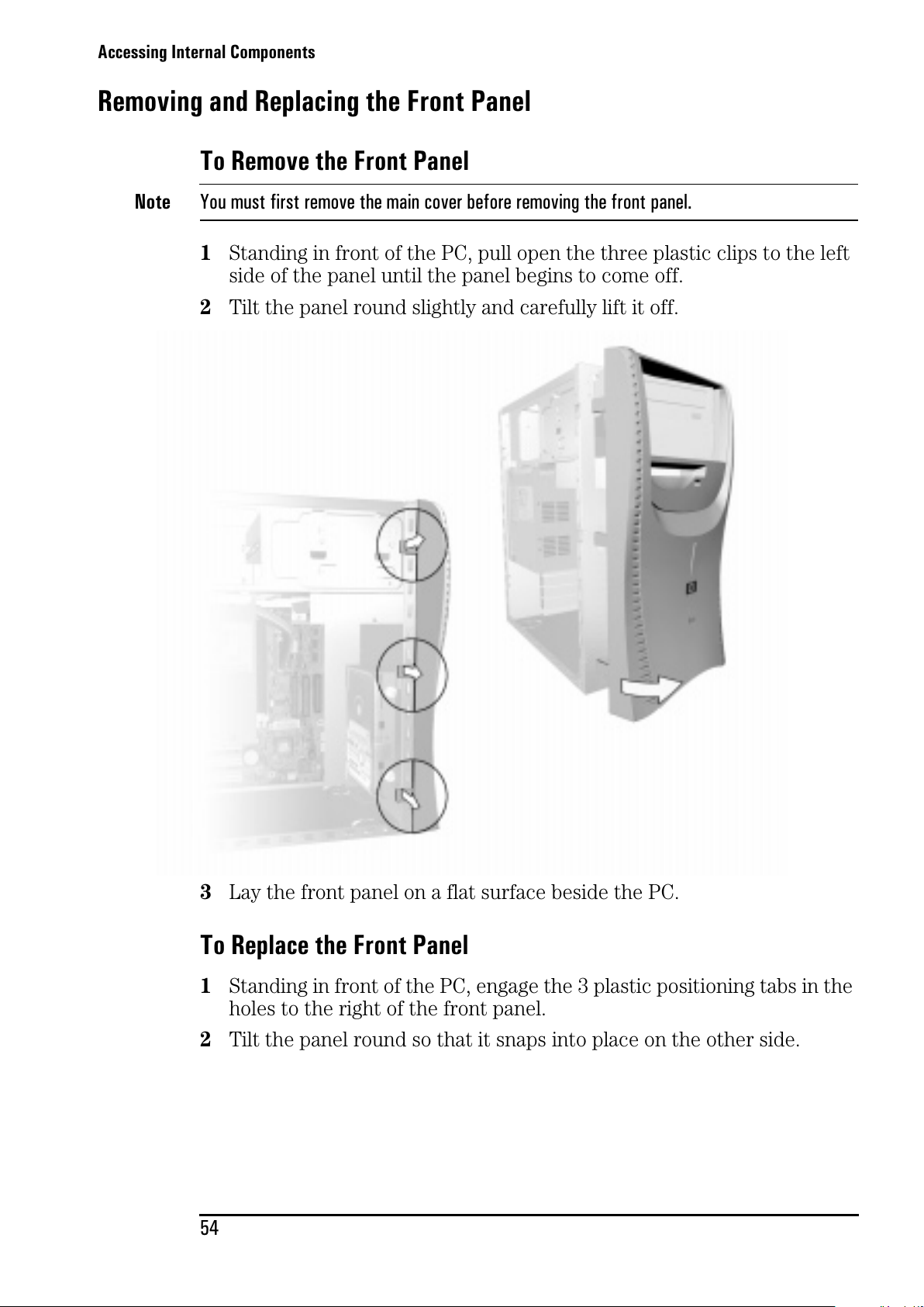
Accessing Internal Components
54
Removing and Replacing the Front Panel
To Remove the Front Panel
Note
You must first remove the main cover before removing the front panel.
1 Standing in front of the PC, pull open the three plastic clips to the left
side of the panel until the panel begins to come off.
2 Tilt the panel round slightly and carefully lift it off.
3 Lay the front panel on a flat surface beside the PC.
To Replace the Front Panel
1 Standing in front of the PC, engage the 3 plastic positioning tabs in the
holes to the right of the front panel.
2 Tilt the panel round so that it snaps into place on the other side.
All manuals and user guides at all-guides.com
Page 63
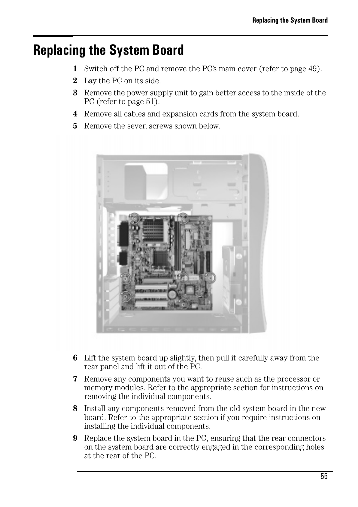
Replacing the System Board
55
Solving Problems
Replacing the System Board
1 Switch off the PC and remove the PC’s main cover (refer to page 49).
2 Lay the PC on its side.
3 Remove the power supply unit to gain better access to the inside of the
PC (refer to page 51).
4 Remove all cables and expansion cards from the system board.
5 Remove the seven screws shown below.
6 Lift the system board up slightly, then pull it carefully away from the
rear panel and lift it out of the PC.
7 Remove any components you want to reuse such as the processor or
memory modules. Refer to the appropriate section for instructions on
removing the individual components.
8 Install any components removed from the old system board in the new
board. Refer to the appropriate section if you require instructions on
installing the individual components.
9 Replace the system board in the PC, ensuring that the rear connectors
on the system board are correctly engaged in the corresponding holes
at the rear of the PC.
All manuals and user guides at all-guides.com
Page 64
Replacing the System Board
56
10 Attach the seven screws.
11 Reconnect the following connectors and cables: status panel connector,
floppy drive cable, CD-ROM cable, hard drive cable, processor fan cable
(if appropriate), power cables and CD audio cable, if you have a CD-
ROM, CD-RW or DVD drive. The power and floppy cables should be held
in place by the cable clamp under the floppy drive. If you can’t
remember how to reconnect them, refer to page 57.
12 Replace the power supply unit. Refer to page 52.
13 Replace the PC’s main cover. Refer to page 49.
All manuals and user guides at all-guides.com
Page 65
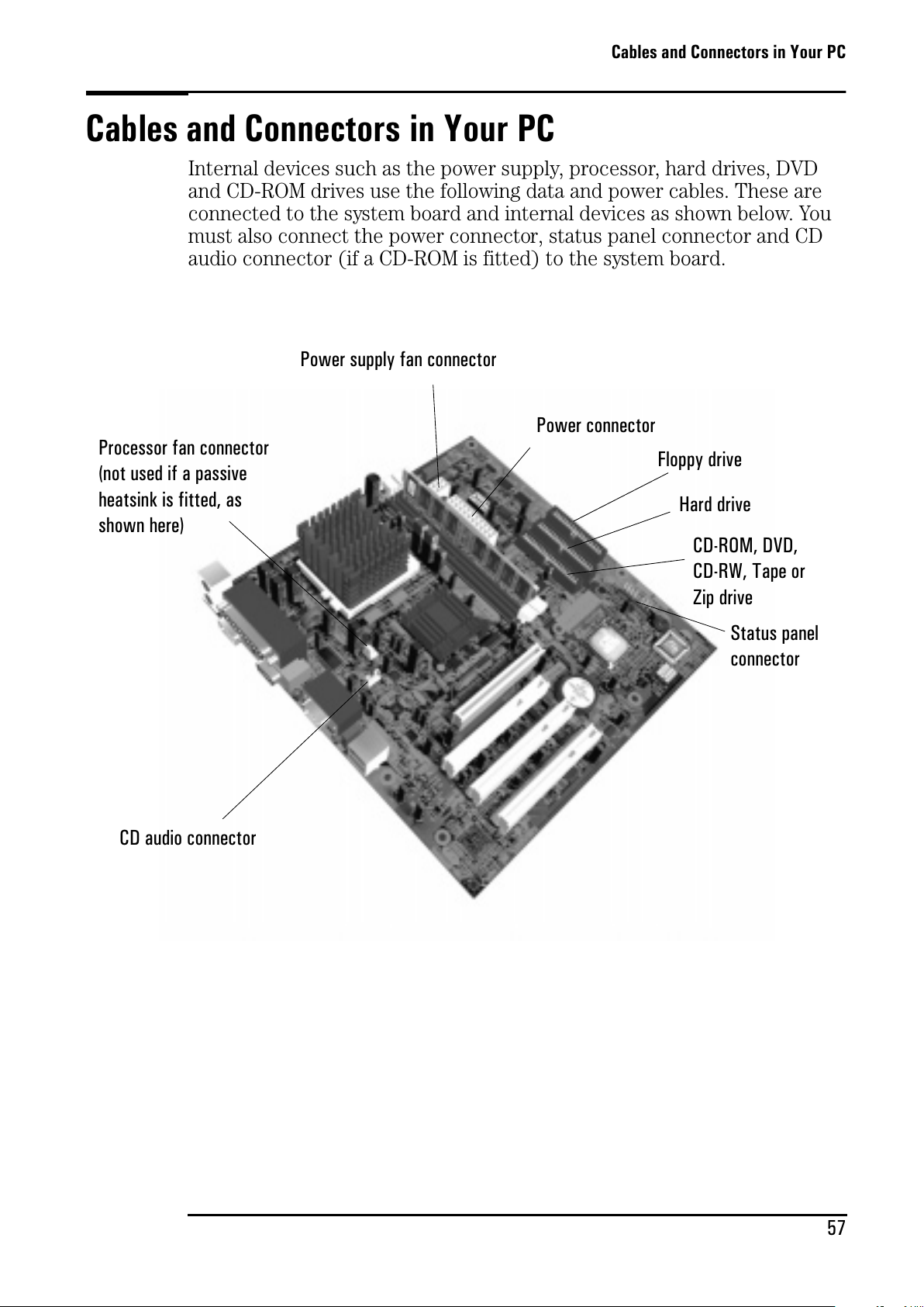
Cables and Connectors in Your PC
57
Cables and Connectors in Your PC
Internal devices such as the power supply, processor, hard drives, DVD
and CD-ROM drives use the following data and power cables. These are
connected to the system board and internal devices as shown below. You
must also connect the power connector, status panel connector and CD
audio connector (if a CD-ROM is fitted) to the system board.
Power connector
CD-ROM, DVD,
CD-RW, Tape or
Zip drive
Hard drive
Floppy drive
CD audio connector
Status panel
connector
Processor fan connector
(not used if a passive
heatsink is fitted, as
shown here)
Power supply fan connector
All manuals and user guides at all-guides.com
Page 66
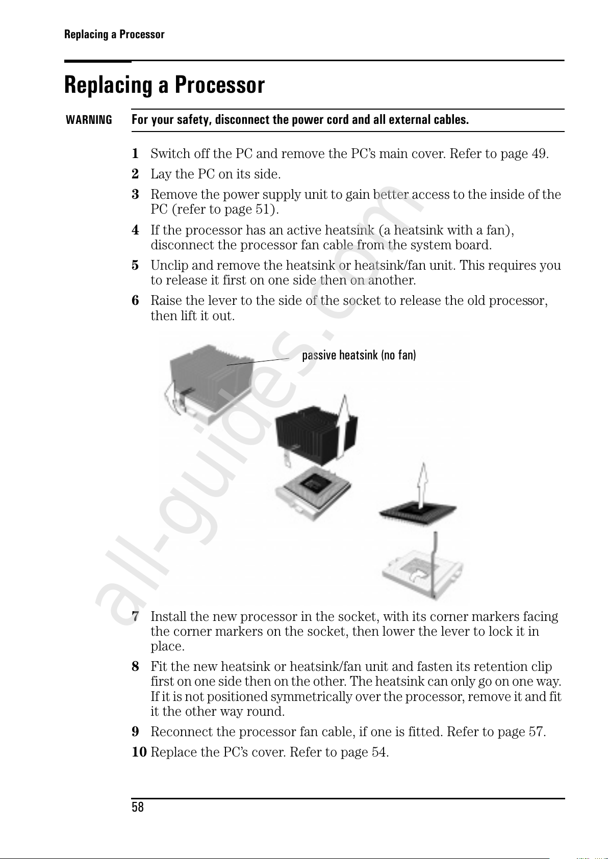
Replacing a Processor
58
Replacing a Processor
WARNING
For your safety, disconnect the power cord and all external cables.
1 Switch off the PC and remove the PC’s main cover. Refer to page 49.
2 Lay the PC on its side.
3 Remove the power supply unit to gain better access to the inside of the
PC (refer to page 51).
4 If the processor has an active heatsink (a heatsink with a fan),
disconnect the processor fan cable from the system board.
5 Unclip and remove the heatsink or heatsink/fan unit. This requires you
to release it first on one side then on another.
6 Raise the lever to the side of the socket to release the old processor,
then lift it out.
7 Install the new processor in the socket, with its corner markers facing
the corner markers on the socket, then lower the lever to lock it in
place.
8 Fit the new heatsink or heatsink/fan unit and fasten its retention clip
first on one side then on the other. The heatsink can only go on one way.
If it is not positioned symmetrically over the processor, remove it and fit
it the other way round.
9 Reconnect the processor fan cable, if one is fitted. Refer to page 57.
10 Replace the PC’s cover. Refer to page 54.
passive heatsink (no fan)
All manuals and user guides at all-guides.com
all-guides.com
Page 67
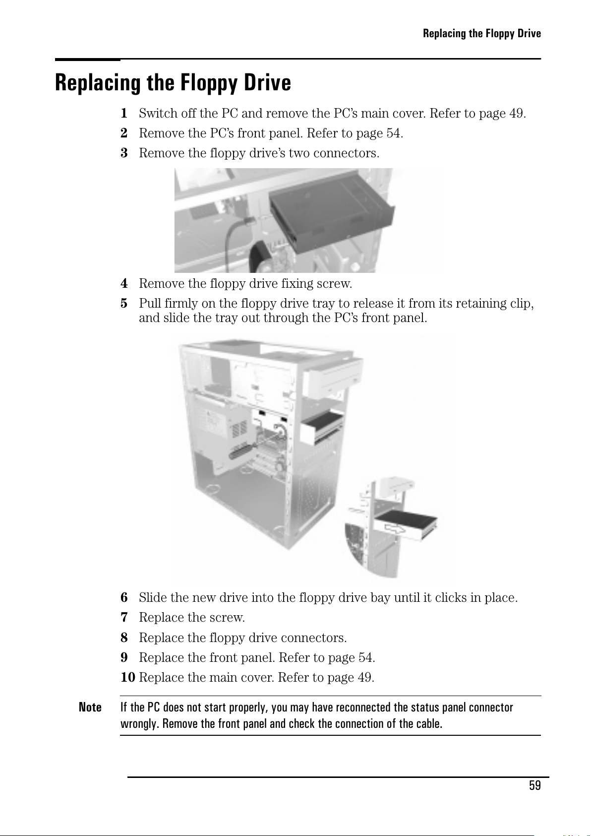
Replacing the Floppy Drive
59
Replacing the Floppy Drive
1 Switch off the PC and remove the PC’s main cover. Refer to page 49.
2 Remove the PC’s front panel. Refer to page 54.
3 Remove the floppy drive’s two connectors.
4 Remove the floppy drive fixing screw.
5 Pull firmly on the floppy drive tray to release it from its retaining clip,
and slide the tray out through the PC’s front panel.
6 Slide the new drive into the floppy drive bay until it clicks in place.
7 Replace the screw.
8 Replace the floppy drive connectors.
9 Replace the front panel. Refer to page 54.
10 Replace the main cover. Refer to page 49.
Note
If the PC does not start properly, you may have reconnected the status panel connector
wrongly. Remove the front panel and check the connection of the cable.
All manuals and user guides at all-guides.com
Page 68
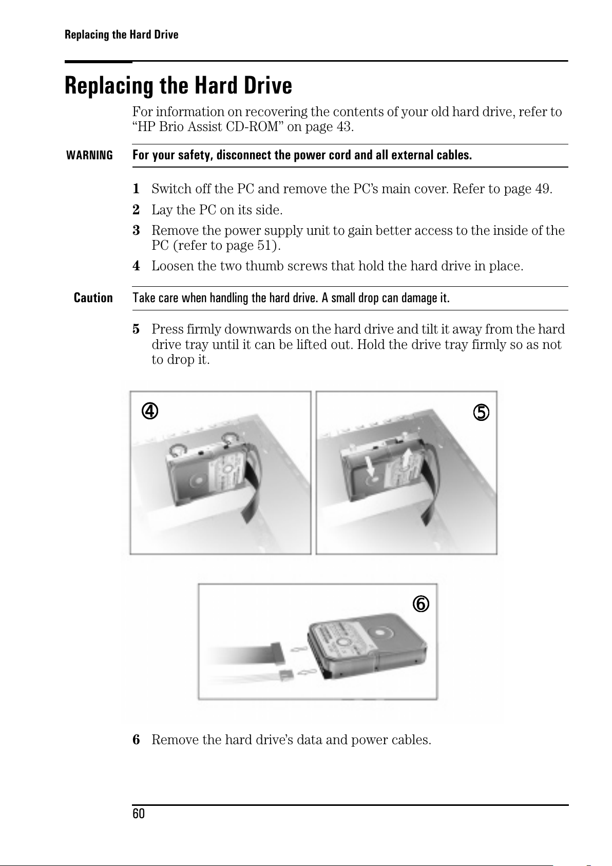
Replacing the Hard Drive
60
Repairing Your e-Vectra
Replacing the Hard Drive
For information on recovering the contents of your old hard drive, refer to
“HP Brio Assist CD-ROM” on page 43.
WARNING
For your safety, disconnect the power cord and all external cables.
1 Switch off the PC and remove the PC’s main cover. Refer to page 49.
2 Lay the PC on its side.
3 Remove the power supply unit to gain better access to the inside of the
PC (refer to page 51).
4 Loosen the two thumb screws that hold the hard drive in place.
Caution
Take care when handling the hard drive. A small drop can damage it.
5 Press firmly downwards on the hard drive and tilt it away from the hard
drive tray until it can be lifted out. Hold the drive tray firmly so as not
to drop it.
6 Remove the hard drive’s data and power cables.
➄➄➄➄
➅➅➅➅
➃➃➃➃
All manuals and user guides at all-guides.com
Page 69
Replacing the Hard Drive
61
7 Carefully insert the two metal retention pins in the holes on the
underside of the hard drive, and ensure that the middle screw hole is
facing the tray’s alignment window.
8 Push down on the drive then tilt it towards the PC chassis until the
middle screw hole appears in the tray’s alignment window.
9 Tighten the two thumb screws.
10 Reconnect the power and data cables. Refer to “Cables and Connectors
in Your PC” on page 57 if you are unsure of which cables to use.
11 Replace the power supply unit.
12 Replace the PC’s main cover. Refer to page 54.
All manuals and user guides at all-guides.com
Page 70
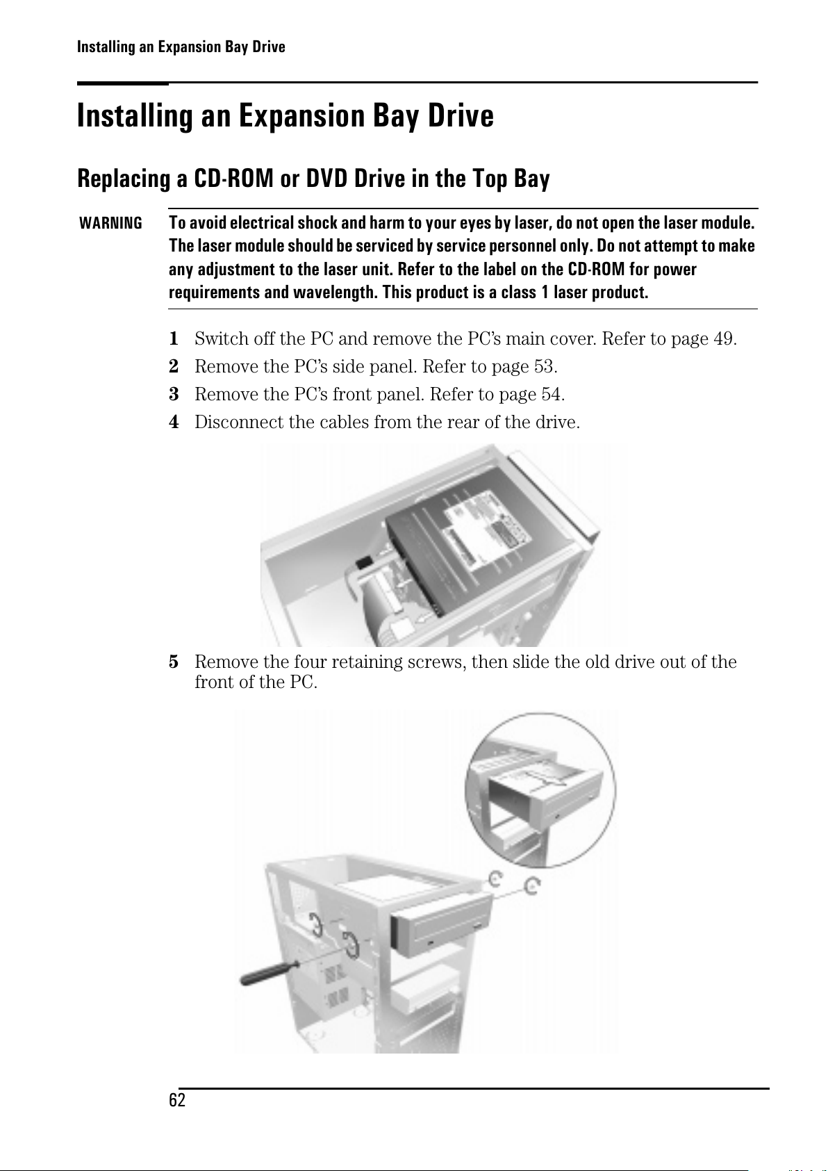
Installing an Expansion Bay Drive
62
Installing an Expansion Bay Drive
Replacing a CD-ROM or DVD Drive in the Top Bay
WARNING
To avoid electrical shock and harm to your eyes by laser, do not open the laser module.
The laser module should be serviced by service personnel only. Do not attempt to make
any adjustment to the laser unit. Refer to the label on the CD-ROM for power
requirements and wavelength. This product is a class 1 laser product.
1 Switch off the PC and remove the PC’s main cover. Refer to page 49.
2 Remove the PC’s side panel. Refer to page 53.
3 Remove the PC’s front panel. Refer to page 54.
4 Disconnect the cables from the rear of the drive.
5 Remove the four retaining screws, then slide the old drive out of the
front of the PC.
All manuals and user guides at all-guides.com
Page 71
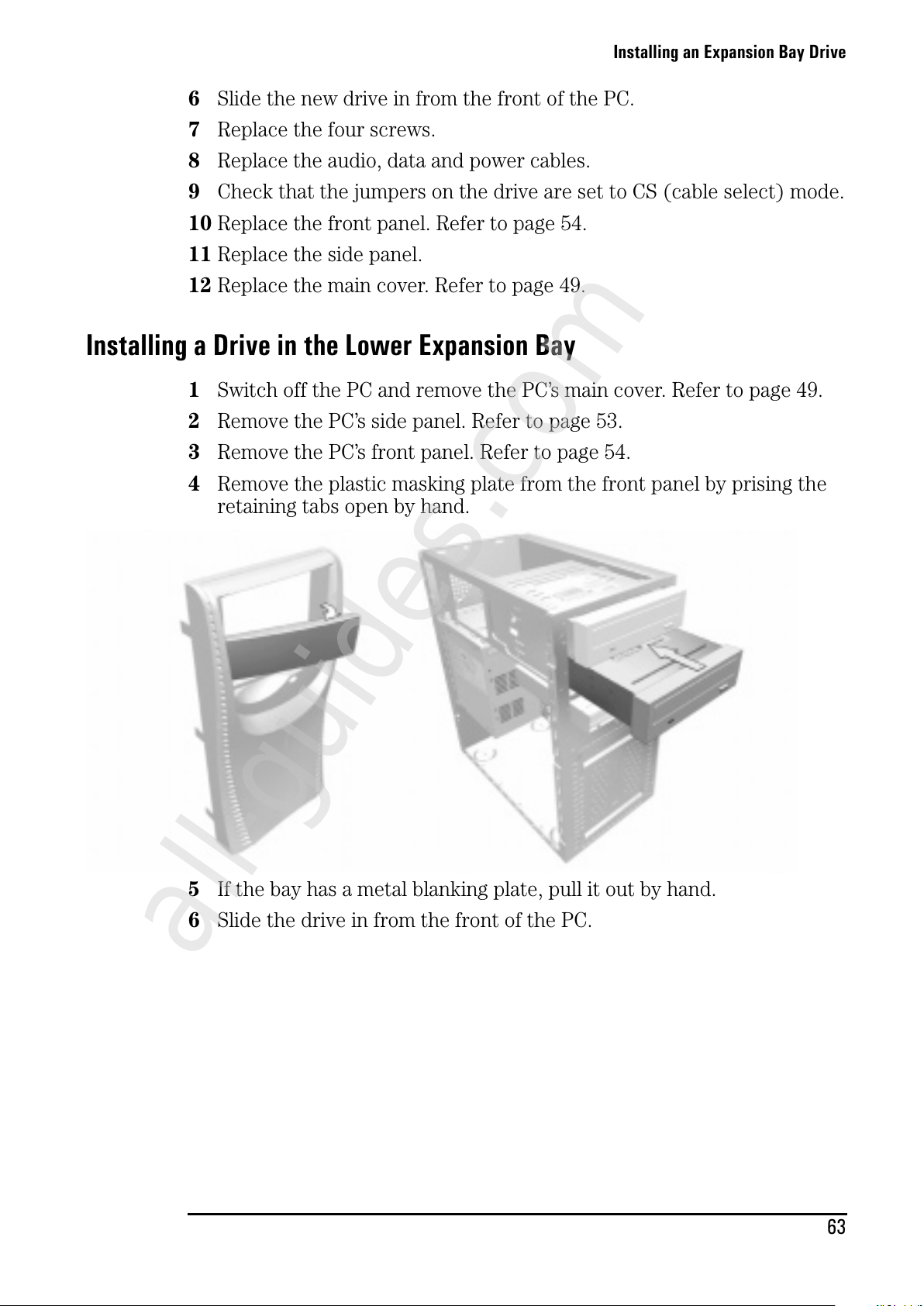
Installing an Expansion Bay Drive
63
6 Slide the new drive in from the front of the PC.
7 Replace the four screws.
8 Replace the audio, data and power cables.
9 Check that the jumpers on the drive are set to CS (cable select) mode.
10 Replace the front panel. Refer to page 54.
11 Replace the side panel.
12 Replace the main cover. Refer to page 49.
Installing a Drive in the Lower Expansion Bay
1 Switch off the PC and remove the PC’s main cover. Refer to page 49.
2 Remove the PC’s side panel. Refer to page 53.
3 Remove the PC’s front panel. Refer to page 54.
4 Remove the plastic masking plate from the front panel by prising the
retaining tabs open by hand.
5 If the bay has a metal blanking plate, pull it out by hand.
6 Slide the drive in from the front of the PC.
All manuals and user guides at all-guides.com
all-guides.com
Page 72
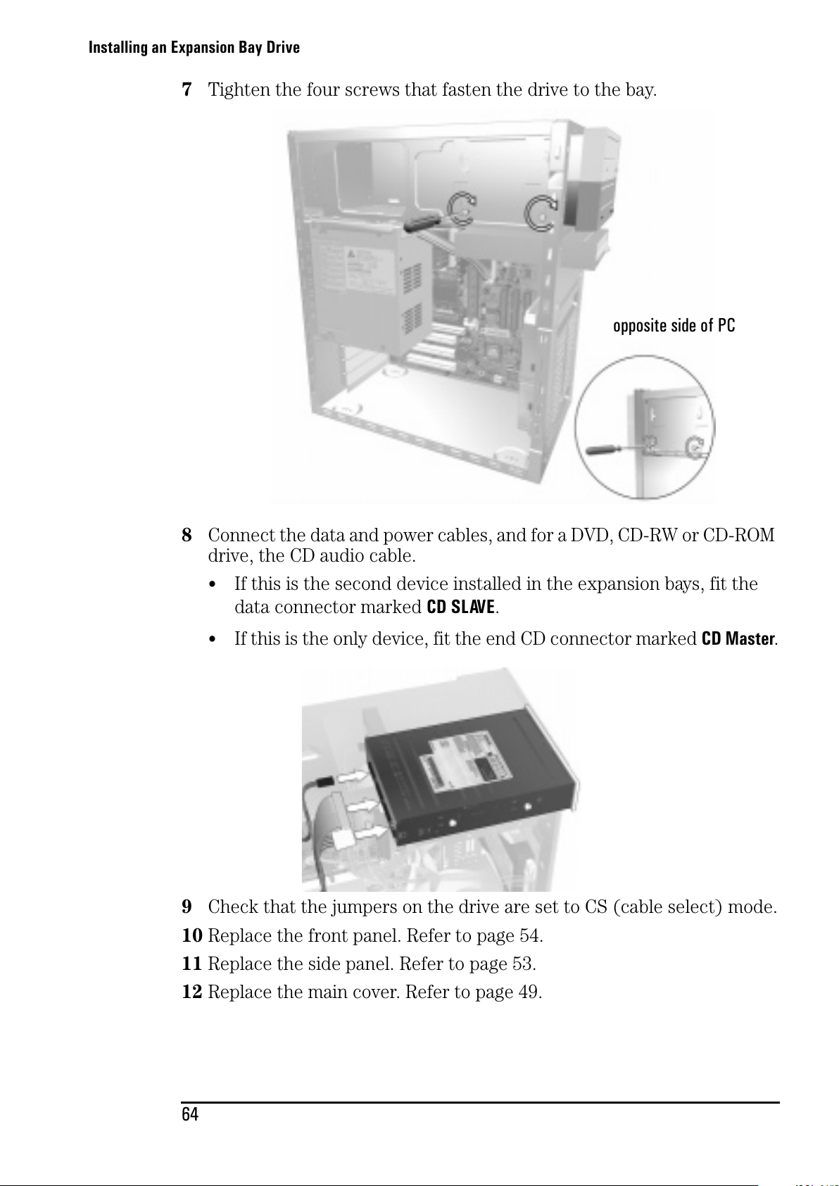
Installing an Expansion Bay Drive
64
7 Tighten the four screws that fasten the drive to the bay.
8 Connect the data and power cables, and for a DVD, CD-RW or CD-ROM
drive, the CD audio cable.
•
If this is the second device installed in the expansion bays, fit the
data connector marked CD SLAVE.
• If this is the only device, fit the end CD connector marked CD Master.
9 Check that the jumpers on the drive are set to CS (cable select) mode.
10 Replace the front panel. Refer to page 54.
11 Replace the side panel. Refer to page 53.
12 Replace the main cover. Refer to page 49.
opposite side of PC
All manuals and user guides at all-guides.com
Page 73
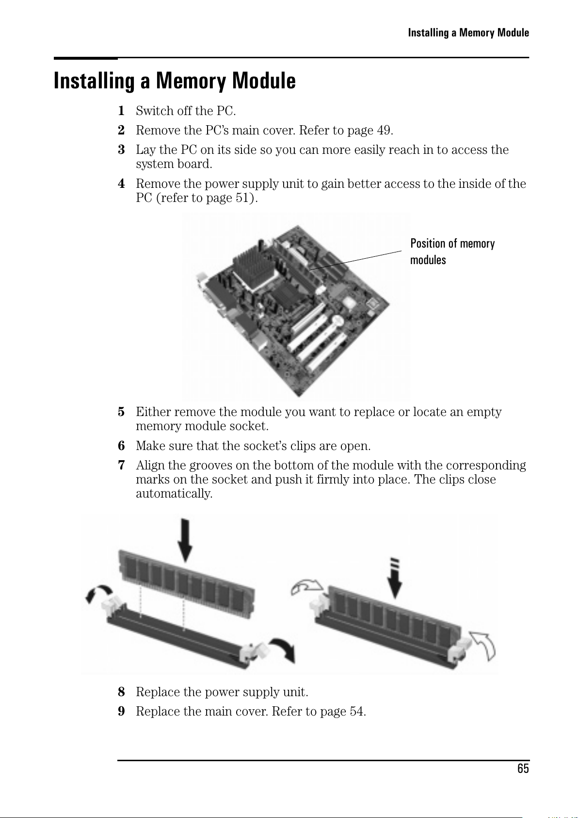
Installing a Memory Module
65
Installing a Memory Module
1 Switch off the PC.
2 Remove the PC’s main cover. Refer to page 49.
3 Lay the PC on its side so you can more easily reach in to access the
system board.
4 Remove the power supply unit to gain better access to the inside of the
PC (refer to page 51).
5 Either remove the module you want to replace or locate an empty
memory module socket.
6 Make sure that the socket’s clips are open.
7 Align the grooves on the bottom of the module with the corresponding
marks on the socket and push it firmly into place. The clips close
automatically.
8 Replace the power supply unit.
9 Replace the main cover. Refer to page 54.
Position of memory
modules
All manuals and user guides at all-guides.com
Page 74
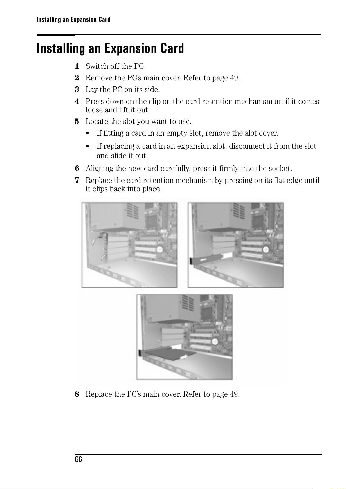
Installing an Expansion Card
66
Installing an Expansion Card
1 Switch off the PC.
2 Remove the PC’s main cover. Refer to page 49.
3 Lay the PC on its side.
4 Press down on the clip on the card retention mechanism until it comes
loose and lift it out.
5 Locate the slot you want to use.
•
If fitting a card in an empty slot, remove the slot cover.
• If replacing a card in an expansion slot, disconnect it from the slot
and slide it out.
6 Aligning the new card carefully, press it firmly into the socket.
7 Replace the card retention mechanism by pressing on its flat edge until
it clips back into place.
8 Replace the PC’s main cover. Refer to page 49.
All manuals and user guides at all-guides.com
Page 75
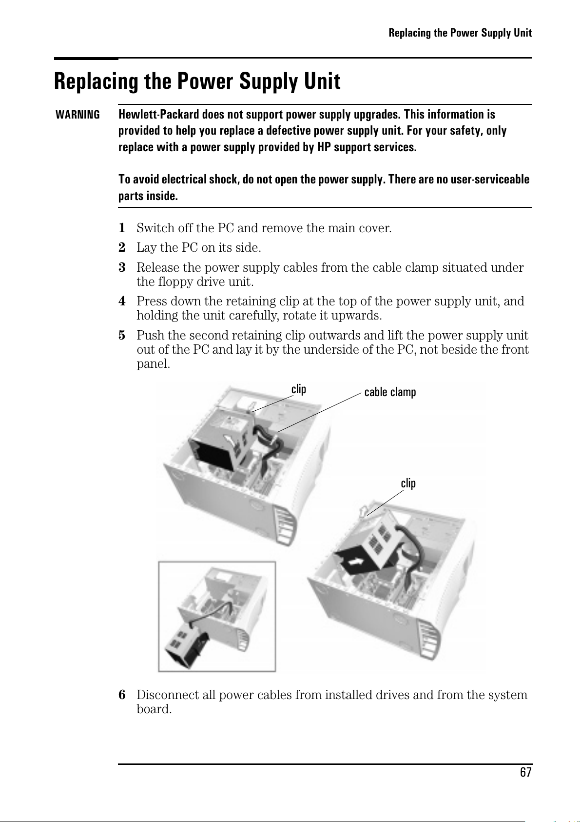
Replacing the Power Supply Unit
67
Replacing the Power Supply Unit
WARNING
Hewlett-Packard does not support power supply upgrades. This information is
provided to help you replace a defective power supply unit. For your safety, only
replace with a power supply provided by HP support services.
To avoid electrical shock, do not open the power supply. There are no user-serviceable
parts inside.
1 Switch off the PC and remove the main cover.
2 Lay the PC on its side.
3 Release the power supply cables from the cable clamp situated under
the floppy drive unit.
4 Press down the retaining clip at the top of the power supply unit, and
holding the unit carefully, rotate it upwards.
5 Push the second retaining clip outwards and lift the power supply unit
out of the PC and lay it by the underside of the PC, not beside the front
panel.
6 Disconnect all power cables from installed drives and from the system
board.
cable clamp
clip
clip
All manuals and user guides at all-guides.com
Page 76
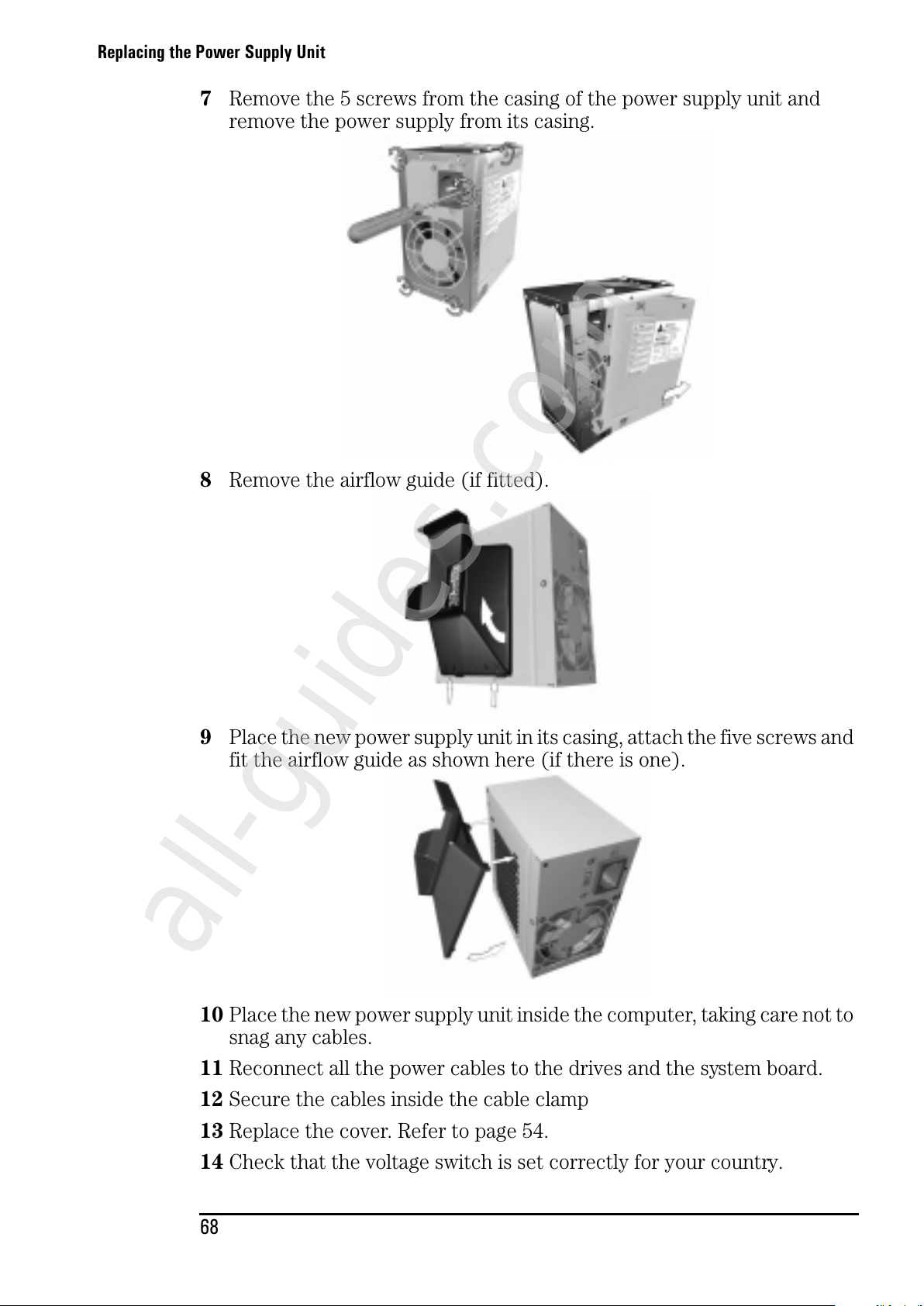
Replacing the Power Supply Unit
68
7 Remove the 5 screws from the casing of the power supply unit and
remove the power supply from its casing.
8 Remove the airflow guide (if fitted).
9 Place the new power supply unit in its casing, attach the five screws and
fit the airflow guide as shown here (if there is one).
10 Place the new power supply unit inside the computer, taking care not to
snag any cables.
11 Reconnect all the power cables to the drives and the system board.
12 Secure the cables inside the cable clamp
13 Replace the cover. Refer to page 54.
14 Check that the voltage switch is set correctly for your country.
All manuals and user guides at all-guides.com
all-guides.com
Page 77
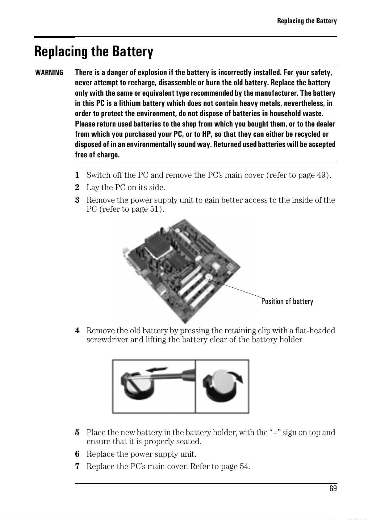
Replacing the Battery
69
Replacing the Battery
WARNING
There is a danger of explosion if the battery is incorrectly installed. For your safety,
never attempt to recharge, disassemble or burn the old battery. Replace the battery
only with the same or equivalent type recommended by the manufacturer. The battery
in this PC is a lithium battery which does not contain heavy metals, nevertheless, in
order to protect the environment, do not dispose of batteries in household waste.
Please return used batteries to the shop from which you bought them, or to the dealer
from which you purchased your PC, or to HP, so that they can either be recycled or
disposed of in an environmentally sound way. Returned used batteries will be accepted
free of charge.
1 Switch off the PC and remove the PC’s main cover (refer to page 49).
2 Lay the PC on its side.
3 Remove the power supply unit to gain better access to the inside of the
PC (refer to page 51).
4 Remove the old battery by pressing the retaining clip with a flat-headed
screwdriver and lifting the battery clear of the battery holder.
5 Place the new battery in the battery holder, with the “+” sign on top and
ensure that it is properly seated.
6 Replace the power supply unit.
7 Replace the PC’s main cover. Refer to page 54.
Position of battery
All manuals and user guides at all-guides.com
Page 78

Replacing the Battery
70
All manuals and user guides at all-guides.com
Page 79
5
Status
Technical Information
This chapter provides technical information on your PC. For more
detailed information, refer to the PC’s datasheet in the library on HP’s web
site: www.hp.com/desktops.
HP Setup Program ......................................................................... page 72
Clearing Your PC’s CMOS (BIOS) Settings ..................................... page 74
Your PC’s BIOS ............................................................................. page 76
Technical Characteristics .............................................................. page 77
All manuals and user guides at all-guides.com
Page 80
HP Setup Program
72
HP Setup Program
The HP Setup program allows you to view and change the configuration of
your HP Brio PC. Sometimes you may also need to enter the Setup
program to reconfigure your PC after installing new hardware
components. The Setup program has online help to guide you through any
changes you have to make.
Entering the Setup Program
To ente r th e Setup program, press F2 when the Hewlett-Packard logo
appears on screen.
Setup Program Menus
Your PC’s Setup program contains a series of menus, which are selected
with the right and left arrow keys on your keyboard. You can select an item
withinamenuwiththeupanddownarrowkeys.Whenanitemisselected,
Setup displays a description of its function on the right of the screen.
The Setup program contains the following menus:
•
Main - for basic information on your configuration including processor
speed, the amount of installed RAM, installed drives, time and date.
•
Advanced - for setting Advanced Features.
• Security - for setting a password to restrict access to your computer.
It is possible to set a Supervisor or a User password. The Supervisor can
change all settings and the User can only change the date and time.
Setting a password will, by preventing access to the Setup menus,
protect your computer's configuration.
You can also disable the floppy, hard drive and CD-ROM drive from
within this menu page to prevent unauthorized use.
•
Power - for selecting power-management modes to reduce the amount of
energy used after specified periods of inactivity.
If your computer stays idle for a certain amount of time, your system
switches from Full Power Mode to Sleep Mode in order to reduce power
consumption.
In Sleep Mode, graphics, the processor and hard disks are stopped. A
user event, such as from the keyboard, can cause the system to resume
to Full Power Mode within a few seconds.
Other events may also wake up the system: a ring on an external
modem, a signal sent by an expansion card (network card etc.).
All manuals and user guides at all-guides.com
Page 81
HP Setup Program
73
•
Boot - for choosing your boot device order and priority.
You can select the order of the devices from which the BIOS (Basic
Input Output System) attempts to boot the operating system. During
the POST (Power On Self-Test), if the BIOS is unsuccessful at booting
from one device, it will try the next one on the Boot Device Priority list
until an operating system is found. The default boot device is the floppy
disk.
•
Exit: for leaving the Setup program.
Setting System Defaults
The Setup program changes system behavior by modifying the power-on
initialization parameters. Setting incorrect values may cause system boot
failure. If this occurs, press the F9 key while you are in the Setup program
to load the Setup program's default values or select Load default values in
the Exit menu of the Setup program. This should enable the computer to
boot properly.
Note If a Supervisor password is set, you need to enter the password to set system defaults.
HP strongly recommends you make a note of any changes you make while in the Setup program.
All manuals and user guides at all-guides.com
all-guides.com
Page 82
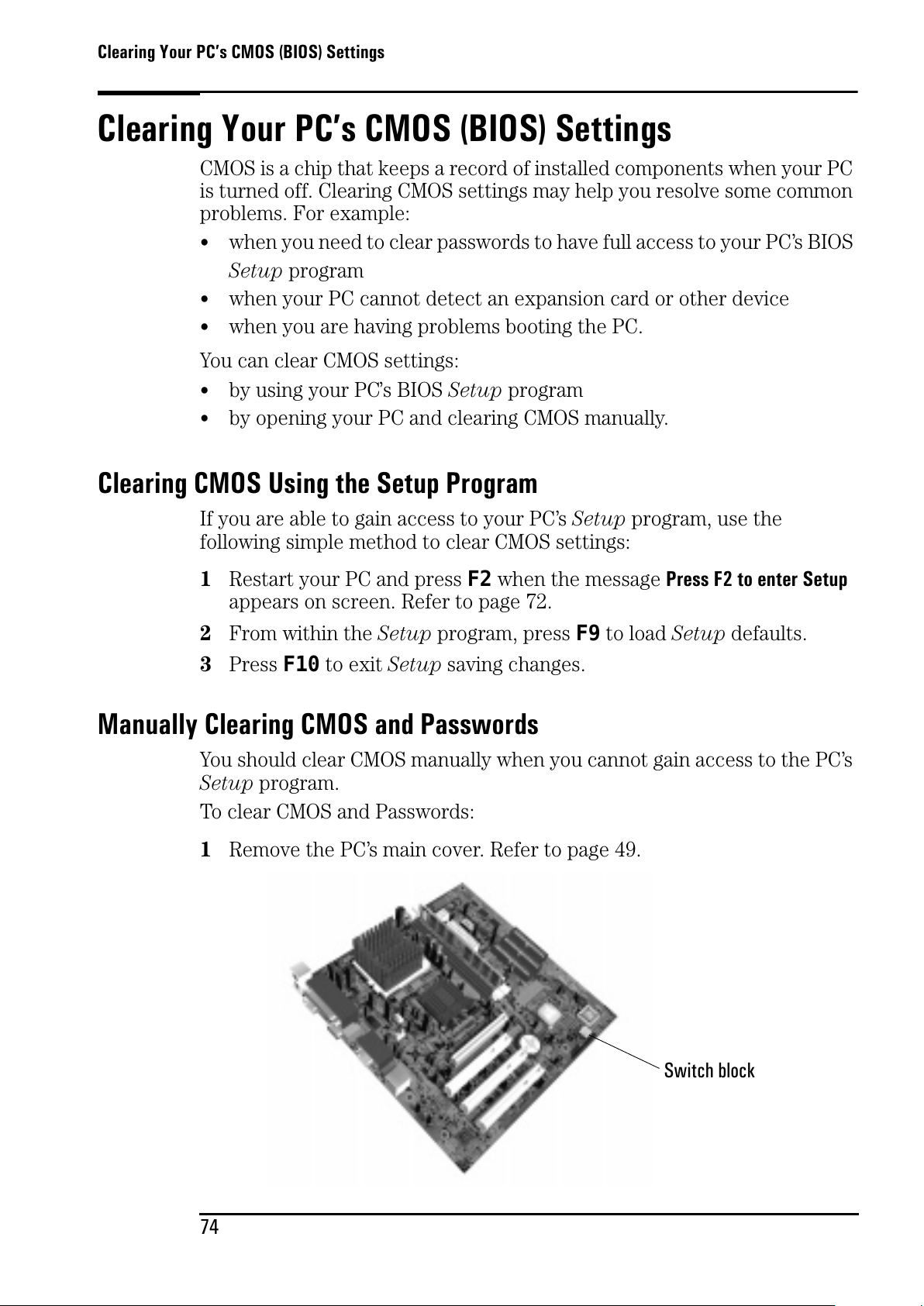
Clearing Your PC’s CMOS (BIOS) Settings
74
Clearing Your PC’s CMOS (BIOS) Settings
CMOS is a chip that keeps a record of installed components when your PC
is turned off. Clearing CMOS settings may help you resolve some common
problems. For example:
• when you need to clear passwords to have full access to your PC’s BIOS
Setup program
• when your PC cannot detect an expansion card or other device
• when you are having problems booting the PC.
You can clear CMOS settings:
• by using your PC’s BIOS Setup program
• by opening your PC and clearing CMOS manually.
Clearing CMOS Using the Setup Program
If you are able to gain access to your PC’s Setup program, use the
following simple method to clear CMOS settings:
1 Restart your PC and press F2 when the message
Press F2 to enter Setup
appears on screen. Refer to page 72.
2 From within the Setup program, press F9 to load Setup defaults.
3 Press F10 to exit Setup saving changes.
Manually Clearing CMOS and Passwords
You should clear CMOS manually when you cannot gain access to the PC’s
Setup program.
To clear CMOS and Passwords:
1 Remove the PC’s main cover. Refer to page 49.
Switch block
All manuals and user guides at all-guides.com
Page 83
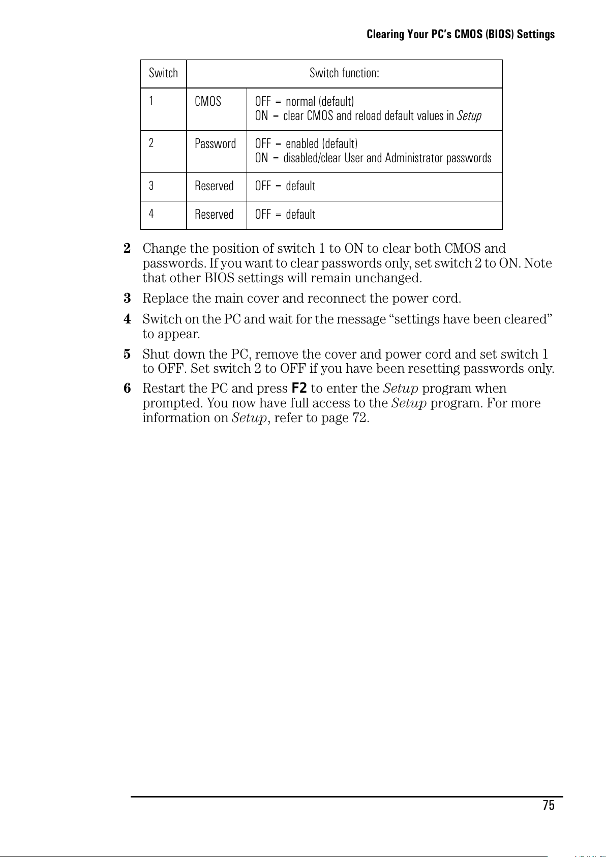
Clearing Your PC’s CMOS (BIOS) Settings
75
2 Changethepositionofswitch1toONtoclearbothCMOSand
passwords. If you want to clear passwords only, set switch 2 to ON. Note
that other BIOS settings will remain unchanged.
3 Replace the main cover and reconnect the power cord.
4 Switch on the PC and wait for the message “settings have been cleared”
to appear.
5 Shut down the PC, remove the cover and power cord and set switch 1
to OFF. Set switch 2 to OFF if you have been resetting passwords only.
6 Restart the PC and press F2 to enter the Setup program when
prompted. You now have full access to the Setup program. For more
information on Setup, refer to page 72.
Switch Switch function:
1
CMOS OFF = normal (default)
ON = clear CMOS and reload default values in Setup
2
Password OFF = enabled (default)
ON = disabled/clear User and Administrator passwords
3
Reserved OFF = default
4
Reserved OFF = default
All manuals and user guides at all-guides.com
Page 84
Your PC’s BIOS
76
Your PC’s BIOS
The BIOS (Basic Input Output System) in your PC has the following roles:
• It tests and configures your PC’s hardware components during the
POST (Power On Self-Test).
• It lets you configure your PC by using the Setup program. See “HP
SetupProgram”onpage72.
• It provides the link between the software running on your PC and your
PC’s hardware.
The BIOS is stored in a chip on the system board. A PC’s BIOS is specific
to that PC.
Updating Your PC’s BIOS
Many problems with your PC can be solved by updating (flashing) the PC’s
BIOS.
Updating (flashing) your BIOS is a simple procedure that involves booting
your PC from a floppy disk containing the new BIOS.
The latest BIOS for your PC along with instructions on updating can be
downloaded from HP’s Brio Support Web site at:
www.hp.com/go/briosupport.
All manuals and user guides at all-guides.com
Page 85
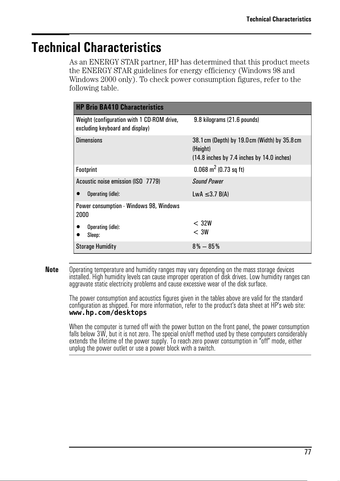
Technical Characteristics
77
Technical Characteristics
As an ENERGY STAR partner, HP has determined that this product meets
the ENERGY STAR guidelines for energy efficiency (Windows 98 and
Windows 2000 only). To check power consumption figures, refer to the
following table.
Note
Operating temperature and humidity ranges may vary depending on the mass storage devices
installed. High humidity levels can cause improper operation of disk drives. Low humidity ranges can
aggravate static electricity problems and cause excessive wear of the disk surface.
The power consumption and acoustics figures given in the tables above are valid for the standard
configuration as shipped. For more information, refer to the product’s data sheet at HP’s web site:
www.hp.com/desktops
When the computer is turned off with the power button on the front panel, the power consumption
falls below 3W, but it is not zero. The special on/off method used by these computers considerably
extends the lifetime of the power supply. To reach zero power consumption in “off” mode, either
unplug the power outlet or use a power block with a switch.
HP Brio BA410 Characteristics
Weight (configuration with 1 CD-ROM drive,
excluding keyboard and display)
9.8 kilograms (21.6 pounds)
Dimensions 38.1cm (Depth) by 19.0cm (Width) by 35.8 cm
(Height)
(14.8 inches by 7.4 inches by 14.0 inches)
Footprint 0.068 m
2
(0.73 sq ft)
Acoustic noise emission (ISO 7779)
• Operating (idle):
Sound Power
LwA
≤ 3.7 B(A)
Power consumption - Windows 98, Windows
2000
• Operating (idle):
•Sleep:
< 32W
<3W
Storage Humidity 8%—85%
All manuals and user guides at all-guides.com
Page 86

Technical Characteristics
78
All manuals and user guides at all-guides.com
all-guides.com
Page 87
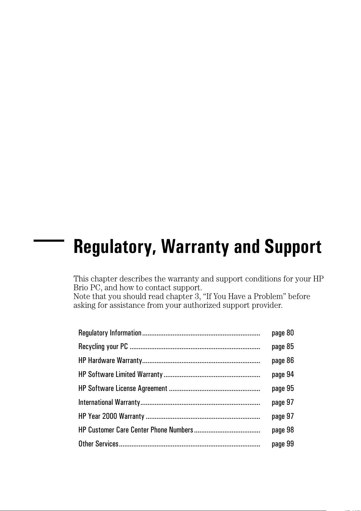
Status
Regulatory, Warranty and Support
This chapter describes the warranty and support conditions for your HP
Brio PC, and how to contact support.
Note that you should read chapter 3, “If You Have a Problem” before
asking for assistance from your authorized support provider.
Regulatory Information.................................................................. page 80
Recycling your PC ......................................................................... page 85
HP Hardware Warranty.................................................................. page 86
HP Software Limited Warranty ...................................................... page 94
HP Software License Agreement ................................................... page 95
International Warranty................................................................... page 97
HP Year 2000 Warranty ................................................................ page 97
HP Customer Care Center Phone Numbers..................................... page 98
Other Services............................................................................... page 99
All manuals and user guides at all-guides.com
Page 88
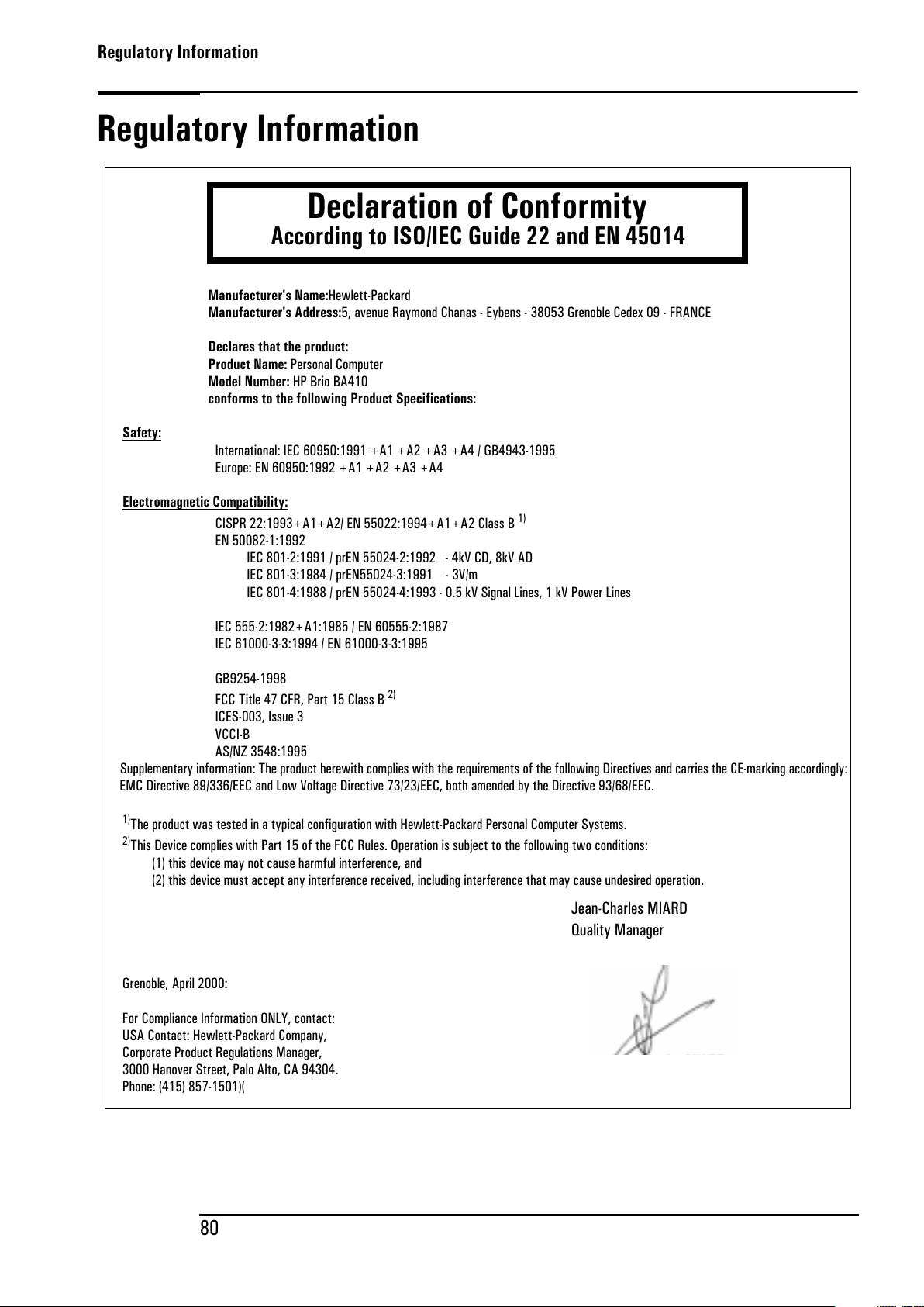
Regulatory Information
80
Regulatory Information
Manufacturer's Name:
Hewlett-Packard
Manufacturer's Address:
5, avenue Raymond Chanas - Eybens - 38053 Grenoble Cedex 09 - FRANCE
Declares that the product:
Product Name:
Personal Computer
Model Number:
HP Brio BA410
conforms to the following Product Specifications:
Safety
:
International: IEC 60950:1991 +A1 +A2 +A3 +A4 / GB4943-1995
Europe: EN 60950:1992 +A1 +A2 +A3 +A4
E
lectromagnetic Compatibility:
CISPR 22:1993+A1+A2/ EN 55022:1994+A1+A2 Class B
1)
EN 50082-1:1992
IEC 801-2:1991 / prEN 55024-2:1992 - 4kV CD, 8kV AD
IEC 801-3:1984 / prEN55024-3:1991 - 3V/m
IEC 801-4:1988 / prEN 55024-4:1993 - 0.5 kV Signal Lines, 1 kV Power Lines
IEC 555-2:1982+A1:1985 / EN 60555-2:1987
IEC 61000-3-3:1994 / EN 61000-3-3:1995
GB9254-1998
FCC Title 47 CFR, Part 15 Class B
2)
ICES-003, Issue 3
VCCI-B
AS/NZ 3548:1995
Supplementary information:
The product herewith complies with the requirements of the following Directives and carries the CE-marking accordingly:
EMC Directive 89/336/EEC and Low Voltage Directive 73/23/EEC, both amended by the Directive 93/68/EEC.
1)
The product was tested in a typical configuration with Hewlett-Packard Personal Computer Systems.
2)
This Device complies with Part 15 of the FCC Rules. Operation is subject to the following two conditions:
(1) this device may not cause harmful interference, and
(2) this device must accept any interference received, including interference that may cause undesired operation.
Grenoble, April 2000:
For Compliance Information ONLY, contact:
USA Contact: Hewlett-Packard Company,
Corporate Product Regulations Manager,
3000 Hanover Street, Palo Alto, CA 94304.
Phone: (415) 857-1501)(
Declaration of Conformity
According to ISO/IEC Guide 22 and EN 45014
Jean-Charles MIARD
Quality Manager
All manuals and user guides at all-guides.com
Page 89
Regulatory Information
81
FCC (for USA only)
Federal Communications Commission Radio Frequency Interference Statement
Warning:
This equipment has been tested and found to comply with the limits for a Class B digital device, pursuant to Part 15
of the FCC Rules. These limits are designed to provide reasonable protection against harmful interference in a
residential installation. This equipment generates, uses, and can radiate radio frequency energy and, if not installed
and used in accordance with the installation manual, may cause harmful interference to radio communications.
However, there is no guarantee that interference will not occur in a particular installation. If this equipment does
cause harmful interference to radio or television reception, which can be determined by turning the equipment off and
on, the user is encouraged to correct the interference by one or more of the following measures:
• Reorient or relocate the receiving antenna.
• Increase the distance between the equipment and the receiver.
• Connect the equipment to an outlet on a different circuit to the one the receiver is connected to.
• Consult your dealer or an experienced radio/TV technician for help.
Hewlett-Packard’s FCC Compliance Tests were conducted using HP-supported peripheral devices and HP shielded
cables, such as those you receive with your system. Changes or modifications not expressly approved by Hewlett-
Packard could void the user’s authority to operate the equipment.
Notice for Canada
This Class B digital apparatus complies with Canadian ICES-003.
Cet appareil numérique de la classe B est conforme à la norme NMB-003 du Canada.
Safety Warning for the USA and Canada
If the power cord is not supplied with the computer, select the proper power cord according to your national electrical
specifications.
USA: use a UL listed type SVT detachable power cord.
Canada: use a CSA certified detachable power cord.
For your safety, never remove the PC’s cover without first removing the power cord and any connection to a
telecommunication network. Always replace the cover before switching on again.
Si le cordon secteur n’est pas livré avec votre ordinateur, utiliser un cordon secteur en accord avec votre code
electrique national.
Canada: utiliser un cordon secteur certifié CSA.
Pour votre sécurité, ne jamais retirer le capot de l’ordinateur sans avoir préalablement débranché le cordon secteur et
toute connection à un réseau de télecommunication. N’oubliez pas de replacer le capot avant de rebrancher le cordon
secteur.
Notice for the Netherlands
Bij dit apparaat zijn batterijen geleverd. Wanneer deze leeg zijn, moet U ze niet weggooien maar inleveren als KCA.
Hinweis für Deutschland: Geräuschemission
Lärmangabe nach Maschinenlärmverordnung - 3 GSGV (Deutschland):
LpA < 70 dB am Arbeitsplatz bei normalem Betrieb nach DIN 45635 T.19
(under normal use in the workplace, as per ISO 7779).
NL
All manuals and user guides at all-guides.com
Page 90
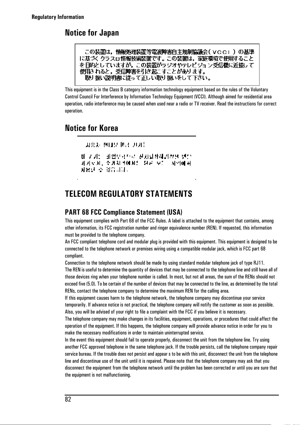
Regulatory Information
82
Notice for Japan
This equipment is in the Class B category information technology equipment based on the rules of the Voluntary
Control Council For Interference by Information Technology Equipment (VCCI). Although aimed for residential area
operation, radio interference may be caused when used near a radio or TV receiver. Read the instructions for correct
operation.
Notice for Korea
TELECOM REGULATORY STATEMENTS
PART 68 FCC Compliance Statement (USA)
This equipment complies with Part 68 of the FCC Rules. A label is attached to the equipment that contains, among
other information, its FCC registration number and ringer equivalence number (REN). If requested, this information
must be provided to the telephone company.
An FCC compliant telephone cord and modular plug is provided with this equipment. This equipment is designed to be
connected to the telephone network or premises wiring using a compatible modular jack, which is FCC part 68
compliant.
Connection to the telephone network should be made by using standard modular telephone jack of type RJ11.
The REN is useful to determine the quantity of devices that may be connected to the telephone line and still have all of
those devices ring when your telephone number is called. In most, but not all areas, the sum of the RENs should not
exceed five (5.0). To be certain of the number of devices that may be connected to the line, as determined by the total
RENs, contact the telephone company to determine the maximum REN for the calling area.
If this equipment causes harm to the telephone network, the telephone company may discontinue your service
temporarily. If advance notice is not practical, the telephone company will notify the customer as soon as possible.
Also, you will be advised of your right to file a complaint with the FCC if you believe it is necessary.
The telephone company may make changes in its facilities, equipment, operations, or procedures that could affect the
operation of the equipment. If this happens, the telephone company will provide advance notice in order for you to
make the necessary modifications in order to maintain uninterrupted service.
In the event this equipment should fail to operate properly, disconnect the unit from the telephone line. Try using
another FCC approved telephone in the same telephone jack. If the trouble persists, call the telephone company repair
service bureau. If the trouble does not persist and appear s to be with this unit, disconnect the unit from the telephone
line and discontinue use of the unit until it is repaired. Please note that the telephone company may ask that you
disconnect the equipment from the telephone network until the problem has been corrected or until you are sure that
the equipment is not malfunctioning.
All manuals and user guides at all-guides.com
Page 91
Regulatory Information
83
The user must use the accessories and cables supplied by the manufacturer to get optimum performance from the
product.
No repairs may be done by the customer.
If trouble is experienced with this equipment, please contact your authorized support provider for repair and warranty
information. If the trouble is causing harm to the telephone network, the telephone company may request you remove
the equipment from the network until the problem is resolved.
This equipment cannot be used on telephone company provided coin service. Connection to Party Line Service is
subject to state tariffs.
When programming and/or making test calls to emergency numbers:
Remain on the line and briefly explain to the dispatcher the reason for the call.
Perform such activities in the off-peak hours such as early morning or late evenings.
The Telephone Consumer Protection Act of 1991 makes it unlawful for any person to use a computer or other
electronic device to send any message via a telephone facsimile machine unless such message clearly contains, in a
margin at the top or bottom of each transmitted page or on the first page of the transmission, the date and time it is
sent and an identification of the business, other entity, or individual sending the message and the telephone number of
the sending machine of such business, other entity, or individual.
In order to program this information into your facsimile, refer to your communications software user manual.
Industry of Canada Notice
The Industry of Canada label identifies certified equipment. This certification means that the equipment meets certain
telecommunications network prospective, operational and safety requirements. The department does not guarantee
the equipment will operate to the user's satisfaction.
Before installing this equipment, make sure you are permitted to connect it to the facilities of the local
Telecommunications Company. You must install the equipment using an acceptable method of connection. In some
cases you may also extend the company's inside wiring for single line individual service by means of certified
connector assembly (telephone extension cord). You should be aware, however, that compliance with the above
conditions may not prevent degradation of service in some situations.
Repairs to certified equipment should be made by an authorized Canadian maintenance facility designed by the
supplier. Any repairs or alterations made by a user to this equipment or equipment malfunctions, may give the
telephone communications company cause to request the user to disconnect the equipment.
For your own protection, make sure that the electrical ground connections of the power utility, telephone lines and
internal metallic water pipes systems, if present, are connected together. This precaution may be particularly
important in rural areas.
Caution:
Do not attempt to make electrical ground connections yourself, contact the appropriate electric inspection
authority or an electrician.
The Ringer Equivalence Number (REN) assigned to each terminal device provides an indication of the maximum number
of terminals allowed to be connected to a telephone interface. The termination on an interface may consist of any
combination of devices subject only to the requirement that the sum of the Ringer Equivalence Numbers of all devices
does not exceed 5.
PAN European Regulatory Note
The equipment has been approved under CTR21. For such products, the following statement is required:
This equipment has been designed to work with all countries’ telephone networks in Europe. Network compatibility is
dependent on internal software settings. Contact your vendor if it is necessary to use the equipment on a different
telephone network or for further product support contact your authorized support provider on the phone numbers
provided in the support and warranty documentation provided with the PC.
All manuals and user guides at all-guides.com
all-guides.com
Page 92
Regulatory Information
84
This equipment has been approved in accordance with Council Decision 98/482/EC for Pan European single terminal
connection to the Public Switched Telephone Network (PSTN). However, due to differences between individual
PSTNs provided in different countries the approval does not, of itself, give an unconditional assurance of successful
operation on every PSTN network termination point.
In the event of problems, you should contact your equipment supplier in the first instance.
Dieses Geraet wurde gemaess der Entscheidung 98/482/EG des Rates europaweit zur Anschaltung als einzelne
Endeinrichtung an das oeffentliche Fernsprechnetz zugelassen. Aufgrund der zwischen den oeffentlichen
Fernsprechnetzen verschiedener Staaten bestehenden Unterschiede Stellt diese Zulassung an sich jedoch keine
unbedingte Gewaehr fuer einen erfolgreichen Betrieb des Geraets an jedem Netzabschlusspunkt dar.
Falls beim Betrieb Probleme auftreten, sollten Sie sich zunaechst an ihren Fachhaendler wenden.
Cet équipement a reçu l'agrément, conformément à la décision 98/482/CE du Conseil, concernant la connexion
paneuropéenne de terminal unique aux Réseaux Téléphoniques Publics Commutés (RTPC). Toutefois, comme il existe
des différences d'un pays à l'autre entre les RTPC, l'agrément en soi ne constitue pas une garantie absolue de
fonctionnement optimal à chaque point de terminaison du réseau RTPC.
En cas de problème, vous devez contacter en premier lieu votre fournisseur.
La presente apparecchiatura terminale è stata approvata in conformità della decione 98/482/CE del Consigho per la
connessione panaeuropea come terminale singolo ad una reteanalogica PSTN. A causa delle differenze tra le reti dei
differenti paesi, l'approvazione non garantisce però di per sé il funzionamento coretto in tutti punti di terminazione di
rete PSTN.
In caso di problemi contattare in primo luogo il fornitore del prodotto.
Este equipo ha sido homologado de conformidad con la Decisión 98/482/CE del Consejo para la conexión panaeuropea
de un terminal simple a la red telefónica pública commutada (RTPC). No obstante, a la vista de la diferencias que
existen entre las RTPC que se ofrecen en diferentes países, la homologación no constituye por si sola una garantia in
condicional de funcionamiento satisfactorio en todos los puntos de terminación de la red de una RTPC.
En caso de surgir algún problema, procede ponerse en contacto en primer lugar el proveedor de equipo.
Dit apparaat is goedgekeurd volgens Beschikking 98/482/EG van de Raad voor de pan-europese aansluiting van
enkelvoudige eindapparatuur op het openbare geschakelde telefoonnetwerk (PSTN). Gezien de verschillen tussen de
individuele PSTN's in de verschillende landen, biedt deze goedkeuring op zichzelf geen onvoorwaardelijke garantie voor
een succesvolle werking op elk PSTN-netwerkaansluitpunt.
Neem bij problemen in eerste instantie contact op met de leverancier van het apparaat.
Network Compatibility Declaration
This product is designed to interwork with the Public Switched Telecommunication Networks in UK, Ireland,
Netherlands, Sweden, Denmark, Finland, Switzerland, Luxembourg, Belgium, France, Germany, Spain, Portugal,
Iceland, Greece, Italy, Norway and Austria.
NEW ZEALAND TELECOM WARNINGS
General
The grant of a Telepermit for any item of terminal equipment indicates only that Telecom has accepted that the item
complies with minimum conditions for connection to its network. It indicates no endorsement of the product by
Telecom, nor does it provide any sort of warranty. Above all, it provides no assurance that any item willwork correctly
in all respects with another item of Telepermitted equipment of a different make or model, nor does it imply that any
product is compatible with all ofTelecom’s network services.
This equipment does not fully meet Telecom’s impedance requirements. Performance limitations may occur when used
in conjunction with some parts of the network.Telecom will accept no responsibility should difficulties arise in such
circumstances.
This equipment shall not be set up to make automatic calls to the Telecom ‘111’ Emergency Service.
All manuals and user guides at all-guides.com
Page 93
Recycling your PC
85
If a charge for local calls is unacceptable, the ‘Dial’ button should NOT be used for local calls. Only the 7-digits of the
local number should be dialled fromyour telephone . D O NO T d i a l t h e a r e a code digit or the ‘0’ prefix.
This equipment may not provide for the effective hand-over of a call to anotherdevice connected to the same line.
Important Notice
Under power failure conditions, this telephone may not operate. Please ensure that a separate telephone, not dependent
on local power, is available for emergency use.
Some parameters required for compliance with Telecom’s Telepermit requirements are dependent on the equipment (PC)
associated with this device. The associated equipment shall be set to operate within the following limits for
compliance with Telecom’s Specification:-
1. (a) There shall be no more than 10 call attempts to the same number within any 30 minute period for any single
manual call initiation, and
(b) The equipment shall go on-hook for a period of not less than 30 seconds between the end of
one attempt and the beginning of the next attempt.
2. Where automatic calls are made to different numbers, the equipment shall go on-line for a period of
not less than 5 seconds between the end of one attempt and the beginning of the next attempt.
3. The equipment shall be set to ensure that calls are answered between 3 and 30 seconds of receipt
of ringing.
All persons using this device for recording telephone conversations shall comply with New Zealand law. This requires
that at least one party to the conversation is to beaware that it is being recorded. In addition, the Principles
enumerated in the Privacy Act 1993 shall be complied with in respect to the nature of the personal information
collected, the purpose for its collection, how it is used and what is disclosed to any other party.
Recycling your PC
HP has a strong commitment toward the environment. Your HP Personal Computer has been designed to respect the
environment as much as possible. HP can also take back your old PC for recycling when it reaches the end of its useful
life. HP has a product take-back program in several countries. The collected equipment is sent to one of HP’srecycling
facilities in Europe or the USA. As many parts as possible are reused. The remainder is recycled. Special care is taken
for batteries and other potentially toxic substances, which are reduced into non-harmful components through a special
chemical process. If you require more details about HP’s product take-back program, contact your local dealer oryour
nearest HP Sales Office.
All manuals and user guides at all-guides.com
Page 94
HP Hardware Warranty
86
HP Hardware Warranty
Important
Before claiming warranty assistance, you should (a) read thoroughly the troubleshooting
information in this manual, (b)
check your precise warranty entitlement by looking at the
warranty entitlement label at the rear of this manual
and (c) check your product receipt
to ensure you are still within the product warranty period.
General
This HP Hardware Warranty statement gives you, the customer, express warranty rights from
HP, the Manufacturer. Please read the rest of this manual for your product-specific warranty
entitlements. In addition, you may also have other legal rights under applicable local law or
special written agreement with HP.
FOR CONSUMER TRANSACTIONS IN AUSTRALIA AND NEW ZEALAND, THE WARRANTY
TERMS CONTAINED IN THIS STATEMENT, EXCEPT TO THE EXTENT LAWFULLY
PERMITTED, DO NOT EXCLUDE, RESTRICT, OR MODIFY BUT ARE IN ADDITION TO
THE MANDATORY STATUTORY RIGHTS APPLICABLE TO THE SALE OF THIS PRODUCT
TO YOU. THE LAWS OF YOUR COUNTRY MAY PROVIDE FOR DIFFERENT WARRANTY
RIGHTS. IF SO, YOUR HP AUTHORIZED SUPPORT PROVIDER OR HP SALES AND
SERVICE OFFICE CAN PROVIDE YOU WITH DETAILS.
Warranty Repair or Replacement
HP Hardware
For the specific warranty period described on the back cover of this guide, HP warrants that
your HP Hardware, Accessory or Supply will be free from defects in materials and
workmanship. Except as indicated above, however, HP does not warrant that any HP
Hardware, Accessory or Supply will operate uninterrupted or error-free.
If, during the product warranty period, HP is unable, within a reasonable time, to repair your
product to a condition as warranted, you will be entitled to a refund (in the amount of the
product purchase price) upon prompt return of the product to your HP Authorized Support
Provider or other HP designate. Unless otherwise stated or agreed upon in writing with HP,
all hardware components must be returned for refund with the entire central processor unit.
The central processor unit (CPU), keyboard, mouse, and Hewlett-Packard accessories inside
the system unit at the time of delivery—such as video adapters, mass storage devices, and
interface controllers—are covered by this warranty.
HP products external to the system unit—such as external storage subsystems, monitors,
printers, accessories, and other peripherals added at a later stage—are covered by the
applicable warranties for those products.
HP software is covered by the HP Software Product Limited Warranty located on page 94 of
this guide.
HP does NOT provide support for this product configured as a network server.We
recommend HP NetServers for your network server requirements.
Unless otherwise stated, and to the extent permitted by local law, hardware products may
contain remanufactured parts (equivalent to new in performance) or parts which may have
All manuals and user guides at all-guides.com
Page 95
HP Hardware Warranty
87
been subject to prior incidental use. HP may repair or replace hardware products (i) with
products which are equivalent in performance to the products being repaired or replaced but
which may have been subject to prior use, (ii) with products which may contain
remanufactured parts equivalent to new in performance or parts which may have been
subject to prior incidental use, or (iii) with products that are equivalent in function to an
original product that has been discontinued.
Non-HP Hardware
Non-HP hardware products and components installed either before or after the purchase of
your HP product, may have different warranty conditions than those of the HP product in
which they are installed.
All non-HP products or peripherals external to the central processor unit—such as external
storage subsystems, monitors, printers, and other peripherals—are covered by the applicable
vendor warranties for those products.
Proof of Purchase and Warranty Period
In order to receive service or support for your hardware product for the warranty period
specified on the back cover of this guide, proof of the original purchase date of the product
may be required in order to establish the warranty period starting date for your product. If
proof of purchase is not available, the manufacturer’s date (located on the product) becomes
the beginning of the warranty period.
Exclusions
Warranty does not apply to defects resulting from: (a) improper or inadequate maintenance
or calibration; (b) software, interfacing, parts or supplies not supplied by HP; (c)
unauthorized repair, maintenance, modification or misuse; (d) operation outside of the
published operating specifications for the product; (e) improper site preparation or
maintenance; (f) virus infection; or (g) such other exclusions as may be expressly set forth in
this Warranty Statement.
Limitation of Implied Warranties
TO THE EXTENT ALLOWED BY APPLICABLE LOCAL LAW, ANY IMPLIED WARRANTY BY
THE MANUFACTURER OF MERCHANTABILITY FOR FITNESS FOR A PARTICULAR
PURPOSE OR OTHER IMPLIED WARRANTIES ARE HEREBY LIMITED TO THE
DURATION OF THE EXPRESSWARRANTY SET FORTH ABOVE.
Exclusive Remedy
TO THE EXTENT ALLOWED BY APPLICABLE LOCALLAW, THE REMEDIES IN THIS
WARRANTY STATEMENT ARE YOUR SOLE AND EXCLUSIVE REMEDIES. EXCEPT AS
INDICATED ABOVE, IN NO EVENT WILL HP BE LIABLE FOR LOSS OF DATA OR FOR
DIRECT, SPECIAL, INCIDENTAL, CONSEQUENTIAL (INCLUDING LOST PROFIT) OR
OTHER DAMAGE, WHETHER BASED IN CONTRACT, TORT OR OTHERWISE.
All manuals and user guides at all-guides.com
Page 96
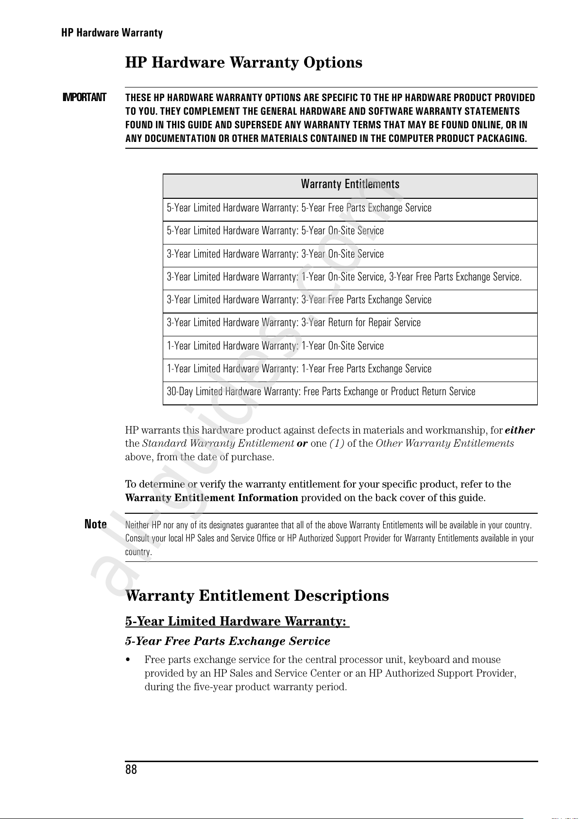
HP Hardware Warranty
88
HP Hardware Warranty Options
IMPORTANT
THESE HP HARDWARE WARRANTY OPTIONS ARE SPECIFIC TO THE HP HARDWARE PRODUCT PROVIDED
TO YOU. THEY COMPLEMENT THE GENERAL HARDWARE AND SOFTWARE WARRANTY STATEMENTS
FOUND IN THIS GUIDE AND SUPERSEDE ANY WARRANTY TERMS THAT MAY BE FOUND ONLINE, OR IN
ANY DOCUMENTATION OR OTHER MATERIALS CONTAINED IN THE COMPUTER PRODUCT PACKAGING.
HP warrants this hardware product against defects in materials and workmanship, for either
the Standard Warranty Entitlement or one (1) of the Other Warranty Entitlements
above, from the date of purchase.
To determine or verify the warranty entitlement for your specific product, refer to the
Warranty Entitlement Information provided on the back cover of this guide.
Note Neither HP nor any of its designates guarantee that all of the above Warranty Entitlements will be available in your country.
Consult your local HP Sales and Service Office or HP Authorized Support Provider for Warranty Entitlements available in your
country.
Warranty Entitlement Descriptions
5-Year Limited Hardware Warranty:
5-Year Free Parts Exchange Service
• Free parts exchange service for the central processor unit, keyboard and mouse
provided by an HP Sales and Service Center or an HP Authorized Support Provider,
during the five-year product warranty period.
Warranty Entitlements
5-Year Limited Hardware Warranty: 5-Year Free Parts Exchange Service
5-Year Limited Hardware Warranty: 5-Year On-Site Service
3-Year Limited Hardware Warranty: 3-Year On-Site Service
3-Year Limited Hardware Warranty: 1-Year On-Site Service, 3-Year Free Parts Exchange Service.
3-Year Limited Hardware Warranty: 3-Year Free Parts Exchange Service
3-Year Limited Hardware Warranty: 3-Year Return for Repair Service
1-Year Limited Hardware Warranty: 1-Year On-Site Service
1-Year Limited Hardware Warranty: 1-Year Free Parts Exchange Service
30-Day Limited Hardware Warranty: Free Parts Exchange or Product Return Service
All manuals and user guides at all-guides.com
all-guides.com
Page 97
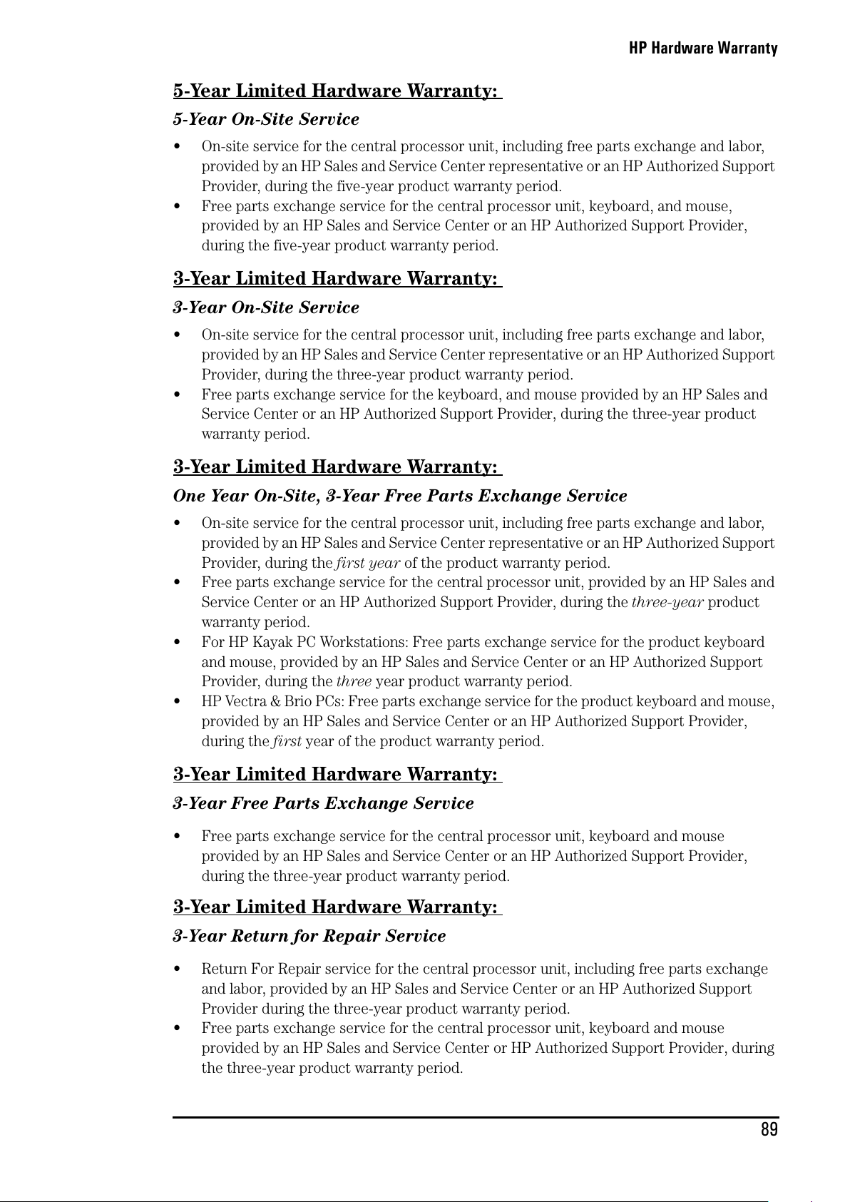
HP Hardware Warranty
89
5-Year Limited Hardware Warranty:
5-Year On-Site Service
• On-site service for the central processor unit, including free parts exchange and labor,
provided by an HP Sales and Service Center representative or an HP Authorized Support
Provider, during the five-year product warranty period.
• Free parts exchange service for the central processor unit, keyboard, and mouse,
provided by an HP Sales and Service Center or an HP Authorized Support Provider,
during the five-year product warranty period.
3-Year Limited Hardware Warranty:
3-Year On-Site Service
• On-site service for the central processor unit, including free parts exchange and labor,
provided by an HP Sales and Service Center representative or an HP Authorized Support
Provider, during the three-year product warranty period.
• Free parts exchange service for the keyboard, and mouse provided by an HP Sales and
Service Center or an HP Authorized Support Provider, during the three-year product
warranty period.
3-Year Limited Hardware Warranty:
One Year On-Site, 3-Year Free Parts Exchange Service
• On-site service for the central processor unit, including free parts exchange and labor,
provided by an HP Sales and Service Center representative or an HP Authorized Support
Provider, during the first year of the product warranty period.
• Free parts exchange service for the central processor unit, provided by an HP Sales and
Service Center or an HP Authorized Support Provider, during the three-year product
warranty period.
• For HP Kayak PC Workstations: Free parts exchange service for the product keyboard
and mouse, provided by an HP Sales and Service Center or an HP Authorized Support
Provider, during the three year product warranty period.
• HP Vectra & Brio PCs: Free parts exchange service for the product keyboard and mouse,
provided by an HP Sales and Service Center or an HP Authorized Support Provider,
during the first year of the product warranty period.
3-Year Limited Hardware Warranty:
3-Year Free Parts Exchange Service
• Free parts exchange service for the central processor unit, keyboard and mouse
provided by an HP Sales and Service Center or an HP Authorized Support Provider,
during the three-year product warranty period.
3-Year Limited Hardware Warranty:
3-Year Return for Repair Service
• Return For Repair service for the central processor unit, including free parts exchange
and labor, provided by an HP Sales and Service Center or an HP Authorized Support
Provider during the three-year product warranty period.
• Free parts exchange service for the central processor unit, keyboard and mouse
provided by an HP Sales and Service Center or HP Authorized Support Provider, during
the three-year product warranty period.
All manuals and user guides at all-guides.com
Page 98
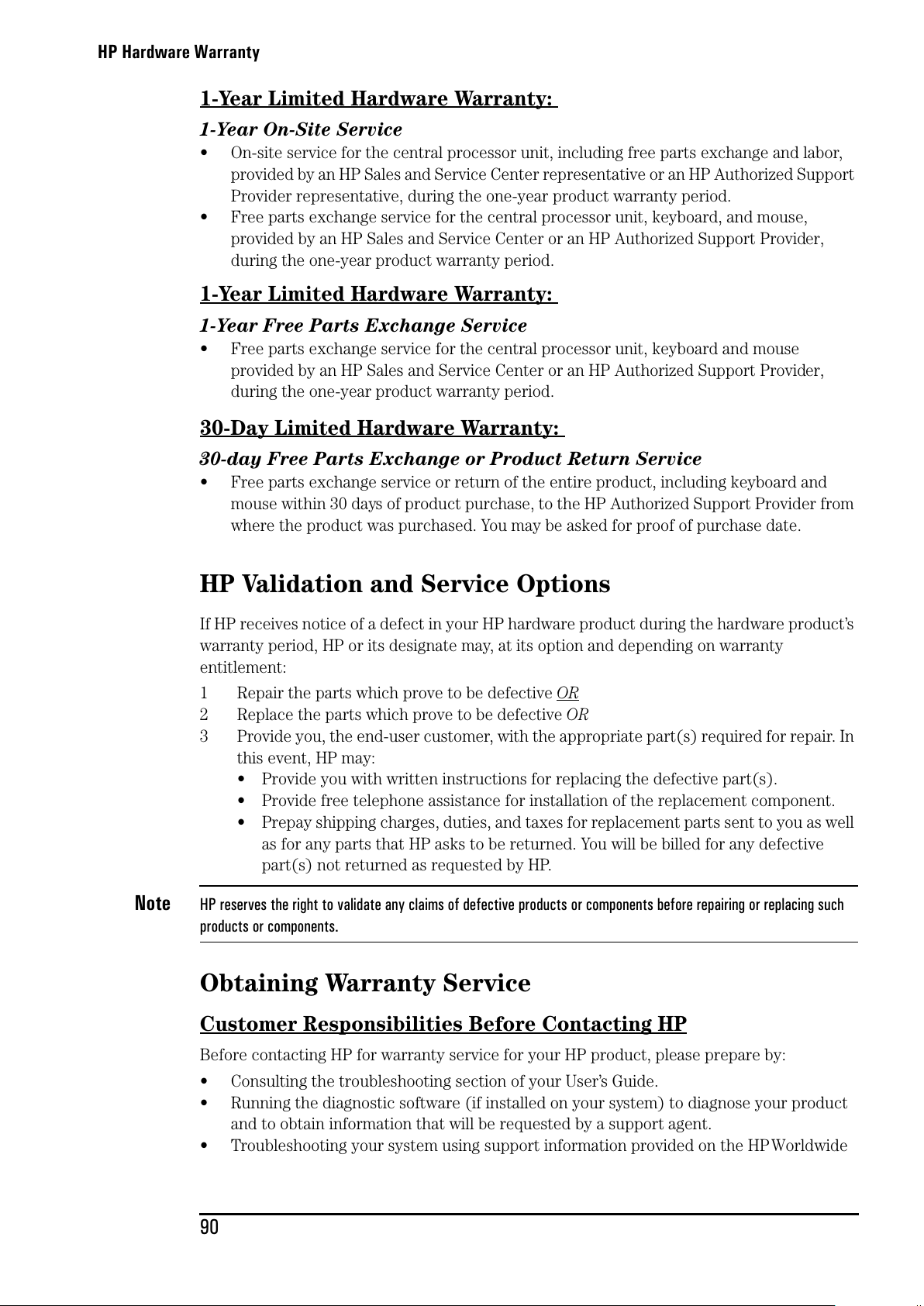
HP Hardware Warranty
90
1-Year Limited Hardware Warranty:
1-Year On-Site Service
• On-site service for the central processor unit, including free parts exchange and labor,
provided by an HP Sales and Service Center representative or an HP Authorized Support
Provider representative, during the one-year product warranty period.
• Free parts exchange service for the central processor unit, keyboard, and mouse,
provided by an HP Sales and Service Center or an HP Authorized Support Provider,
during the one-year product warranty period.
1-Year Limited Hardware Warranty:
1-Year Free Parts Exchange Service
• Free parts exchange service for the central processor unit, keyboard and mouse
provided by an HP Sales and Service Center or an HP Authorized Support Provider,
during the one-year product warranty period.
30-Day Limited Hardware Warranty:
30-day Free Parts Exchange or Product Return Service
• Free parts exchange service or return of the entire product, including keyboard and
mouse within 30 days of product purchase, to the HP Authorized Support Provider from
where the product was purchased. You may be asked for proof of purchase date.
HP Validation and Service Options
If HP receives notice of a defect in your HP hardware product during the hardware product’s
warranty period, HP or its designate may, at its option and depending on warranty
entitlement:
1 Repair the parts which prove to be defective OR
2 Replace the parts which prove to be defective OR
3 Provide you, the end-user customer, with the appropriate part(s) required for repair. In
this event, HP may:
• Provide you with written instructions for replacing the defective part(s).
• Provide free telephone assistance for installation of the replacement component.
• Prepay shipping charges, duties, and taxes for replacement parts sent to you as well
as for any parts that HP asks to be returned. You will be billed for any defective
part(s) not returned as requested by HP.
Note HP reserves the right to validate any claims of defective products or components before repairing or replacing such
products or components.
Obtaining Warranty Service
Customer Responsibilities Before Contacting HP
Before contacting HP for warranty service for your HP product, please prepare by:
• Consulting the troubleshooting section of your User’s Guide.
• Running the diagnostic software (if installed on your system) to diagnose your product
and to obtain information that will be requested by a support agent.
• Troubleshooting your system using support information provided on the HPWorldwide
All manuals and user guides at all-guides.com
Page 99
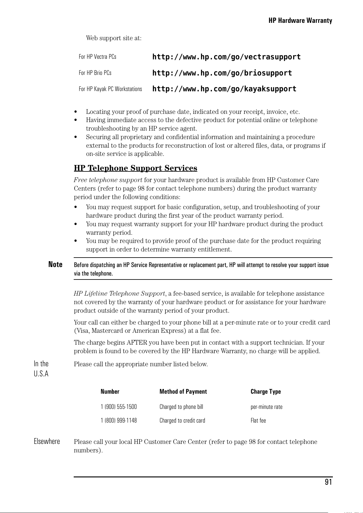
HP Hardware Warranty
91
Web support site at:
• Locating your proof of purchase date, indicated on your receipt, invoice, etc.
• Having immediate access to the defective product for potential online or telephone
troubleshooting by an HP service agent.
• Securing all proprietary and confidential information and maintaining a procedure
external to the products for reconstruction of lost or altered files, data, or programs if
on-site service is applicable.
HP Telephone Support Services
Free telephone support for your hardware product is available from HP Customer Care
Centers (refer to page 98 for contact telephone numbers) during the product warranty
period under the following conditions:
• You may request support for basic configuration, setup, and troubleshooting of your
hardware product during the first year of the product warranty period.
• You may request warranty support for your HP hardware product during the product
warranty period.
• You may be required to provide proof of the purchase date for the product requiring
support in order to determine warranty entitlement.
Note Before dispatching an HP Service Representative or replacement part, HP will attempt to resolve your support issue
via the telephone.
HP Lifeline Telephone Support, a fee-based service, is available for telephone assistance
not covered by the warranty of your hardware product or for assistance for your hardware
product outside of the warranty period of your product.
Your call can either be charged to your phone bill at a per-minute rate or to your credit card
(Visa, Mastercard or American Express) at a flat fee.
The charge begins AFTER you have been put in contact with a support technician. If your
problem is found to be covered by the HP Hardware Warranty, no charge will be applied.
In the
U.S.A
Please call the appropriate number listed below.
Elsewhere
Please call your local HP Customer Care Center (refer to page 98 for contact telephone
numbers).
For HP Vectra PCs
http://www.hp.com/go/vectrasupport
For HP Brio PCs
http://www.hp.com/go/briosupport
For HP Kayak PC Workstations
http://www.hp.com/go/kayaksupport
Number Method of Payment Charge Type
1 (900) 555-1500 Charged to phone bill per-minute rate
1 (800) 999-1148 Charged to credit card Flat fee
All manuals and user guides at all-guides.com
Page 100
HP Hardware Warranty
92
Obtaining On-Site Service
If your product is eligible for on-site warranty service, you must either contact an HP
Customer Care Center, an HP Sales and Service Office or a participating HP Authorized
Support Provider. You may be required to supply proof of the purchase date.
On-site visits resulting from defects in non-HP products—whether internal or external to the
central processor unit—are subject to standard per-incident travel and labor charges.
On-site service visits are subject to the following conditions:
• You must verify that the latest version of the BIOS is installed on your product. You may
be asked to install the latest version of the BIOS before an HP Sales and Service Center
representative or HP Authorized Support Provider representative is dispatched to your
site.
• You must provide: access to the product; adequate working space and facilities within a
reasonable distance of the product; access to and use of all information and facilities
determined necessary by HP to service the product; and operating supplies and
consumables such as you would use during normal operation.
• You,orarepresentativeforyou,mustbepresentatalltimes.Youmuststateifthe
product is being used in an environment which poses a potential health hazard to repair
personnel. HP or the servicing dealer may require that the product be maintained by
customer personnel under direct HP or dealer supervision.
• On-site service for this product is restricted or unavailable in certain locations. In HP
Excluded Travel Areas — areas where geographical obstacles, undeveloped roads, or
unsuitable public transportation prohibit routine travel— service is provided on a
negotiated basis at extra charge.
• Response time for on-site service in an HP Service Travel Area is normally next business
day (excluding HP holidays) for HP Travel Zones 1-3 (generally 100 miles or 160 km
from the HP office). Response time is second business day for Zones 4 and 5 (200 miles,
320 km); third business day for Zone 6 (300 miles, 480 km); and negotiated beyond Zone
6. Worldwide Customer Support Travel information is available from any HP Sales and
Service Office. Response time for on-site service is subject to changes from standard
conditions based upon non-local parts availability.
• Travel restrictions and response times for HP Authorized Support Providers are defined
by the participating HP Authorized Support Providers.
Obtaining Free Parts Exchange Service
For Free Parts Exchange service, you must contact either an HP Customer Care Center, an
HP Sales and Service Office, or a participating HP Authorized Support Provider. You will be
sent the necessary replacement parts for performing any repairs yourself.
In addition, obtaining Free Parts Exchange service is subject to the following conditions:
• If you contact an HP Customer Care Center and you are to receive a replacement part,
you will not be billed for the call.If you are asked to return the entire bundled product
for repair, the necessary parts will be provided free of charge; however, you will be billed
for labor to repair your product.
• HP reserves the right to validate any claims of defective parts before sending
replacements for any such parts.
• You must verify that the latest version of the BIOS is installed on your product. You may
be asked to install the latest version of the BIOS before a free replacement part is sent to
you.
• HP may provide you with necessary written instructions for replacing the defective
part(s).
All manuals and user guides at all-guides.com
 Loading...