

Page 1

FR31
MAINBOARD
MANUAL
DOC No.: M99C05
Rev. : A0
Date : 10, 2000
Part No. : 25-11534-20
Page 2

Notice
Handling Precautions
Warning:
1. Static electricity may cause damage to the integrated circuits on
the mainboard. Before handling any motherboard outside of its
protective packaging, ensure that your body is not electrostatically
charged.
2. There is a danger of explosion if the battery is incorrectly replaced.
Replace only with the same or an equivalent type of battery as
recommended by the manufacturer.
3. Discard used batteries according to the manufacturer’s
instructions.
Observe the following basic precautions when handling the motherboard
or other computer components:
n Wear a static wrist strap which fits around your wrist and is
connected to a natural earth ground.
n Touch a grounded or anti-static surface or a metal fixture such as a
water pipe.
n Ensure add-on cards, mainboards, and models do not come into
contact with the golden fingers connectors, plugged into the expansion slot.
The above methods prevent static build-up and allow it to be discharged
properly.
Trademark
All trademarks mentioned in this manual are registered property of
the respective owners.
Handling Precautions
This manual may not, in whole or in part, be photocopied, reproduced,
transcribed, translated, or transmitted in whatever form without the
written consent of the manufacturer, except for copies retained by the
purchaser for personal archival purposes.
Page 3

T able of Contents
Table of Contents
Chapter 1 Overview
Package Checklist .......................................................................... 1 - 2
The FR31 Mainboard ................................................................ 1- 3
Main Features................................................................................ 1-4
ACPI Ready ................................................................................... 1- 6
FIC Unique Innovation for Users (NOVUS) -
Enhanced Mainboard Features and System Support .................... 1-6
Chapter 2 Installation Procedures
Quick Reference (from Page 2-2 to 2-4) .......................................... 2- 2
Mainboard Layout .................................................................... 2-2
1). CPU/Bus Speed Ratio Select,
Clear CMOS, Clear Password, Front Side Bus
Speed Select, AMR Card Function Enabled ................ 2- 3
2). Front Panel Block Cable Connection ............................ 2- 4
3). CPU Fan Installation .................................................... 2- 4
1). Set System Jumpers/Switches................................................... 2 - 5
Clear CMOS: SW1-5 .......................................................... 2- 6
Clear Password: SW1-6 ..................................................... 2- 6
AMR Card Function Enable: J7......................................... 2- 7
2). Install RAM Modules ............................................................... 2- 7
3). Install the CPU .......................................................................... 2 - 8
CPU/Bus Speed Ratio Select: SW1-1/2/3/4 ....................... 2 -9
Front Side Bus Speed Select: J3/J4/J5 ............................... 2-10
4). Install Expansion Cards............................................................. 2-11
5). Connect Devices....................................................................... 2-12
Floppy Diskette Drive Connector: FLOPPY ...................... 2-12
IDE HDD Device Connectors: PRIMARY, SECONDARY.. 2-13
Infrared Connector: IR....................................................... 2-13
A TX Power Connector: POWER ....................................... 2-14
Optional Audio Alert II Module Connector: NOVUS ....... 2-14
CPU Fan Connector: J2 ..................................................... 2-15
System Case Fan Connector: J6 ........................................ 2-15
W ake-On-LAN Connector: WOL ...................................... 2-16
CD Audio-In Connectors: CD_IN1, CD_IN2..................... 2-16
i
Page 4

FR31 Mainboard Manual
Front Panel Block Connector: FPNL.................................. 2-17
PS/2 Keyboard and Mouse Connector: KB, MS ............... 2-18
Universal Serial Bus Connectors: Rear USBs, Front USBs 2-18
Serial Port Connectors: COM1, COM2 .............................. 2-19
V ideo Graphics Accelerator Connector: VGA ................... 2-19
Printer Connector: LPT...................................................... 2-20
Audio I/O Jacks: LINE_OUT , LINE_IN, MIC_IN,
FNT_AUDIO..................................................................... 2-20
Game/MIDI Connector: GAME ......................................... 2-21
Chapter 3 BIOS Setup
CMOS Setup Utility ....................................................................... 3- 1
Standard CMOS Setup................................................................... 3- 2
Hard Disk Configurations.......................................................... 3- 2
Advanced BIOS Features .............................................................. 3 -3
Advanced Chipset Features .......................................................... 3-8
Integrated Peripherals.................................................................... 3-12
Power Management Setup ............................................................. 3-17
PNP/PCI Configurations ................................................................ 3-22
PC Health Status ............................................................................ 3-24
Frequency/Voltage Control ............................................................ 3-25
Load Fail-Safe Defaults.................................................................. 3-26
Load Optimized Defaults................................................................ 3-26
Supervisor/User Password ............................................................ 3-27
Save and Exit Setup ....................................................................... 3-28
Exit without Saving ........................................................................ 3-28
Quick Reference (German) G-1
Quick Reference (French) F- 1
Quick Reference (Spanish) S-1
Quick Reference (Japanese) J-1
Quick Reference (Chinese) C- 1
Quick Reference (Simplified Chinese ) SC-1
ii
Page 5

Quick Reference
The mainboard has several user-adjustable jumpers and/or switches on the board that
allow you to configure your system to suit your requirements. This quick reference
contains information on the various hardware settings on your mainboard.
To set up your computer, you must complete the following steps:
Quick Reference
■ Step 1 - Set system jumpers/switches
■ Step 2 - Install system memory modules
■ Step 3 - Install the Central Processing Unit (CPU)
■ Step 4 - Install expansion cards
■ Step 5 - Connect ribbon cables, cabinet wires, and power supply
■ Step 6 - Set up BIOS software
■ Step 7 - Set up supporting software tools
WARNING: Excessive torque may damage the mainboard. When
using an electric screwdriver on the mainboard, make sure that
the torque is set to the allowable range of 5.0 ~ 8.0kg/cm.
Mainboard components contain very delicate Integrated Circuit
(IC) chips. To prevent static electricity from harming any of the
mainboard’s sensitive components, you should follow the
following precautions whenever working on the computer:
1. Unplug the computer when working on the inside.
2. Hold components by the edges and try not to touch the IC
||||chips, leads, or circuitry.
3. Wear an anti-static wrist strap which fits around the wrist.
4. Place components on a grounded anti-static pad or on the bag
that came with the component whenever the components are
separated from the system.
4 - 1
Page 6
FR31 Mainboard Manual
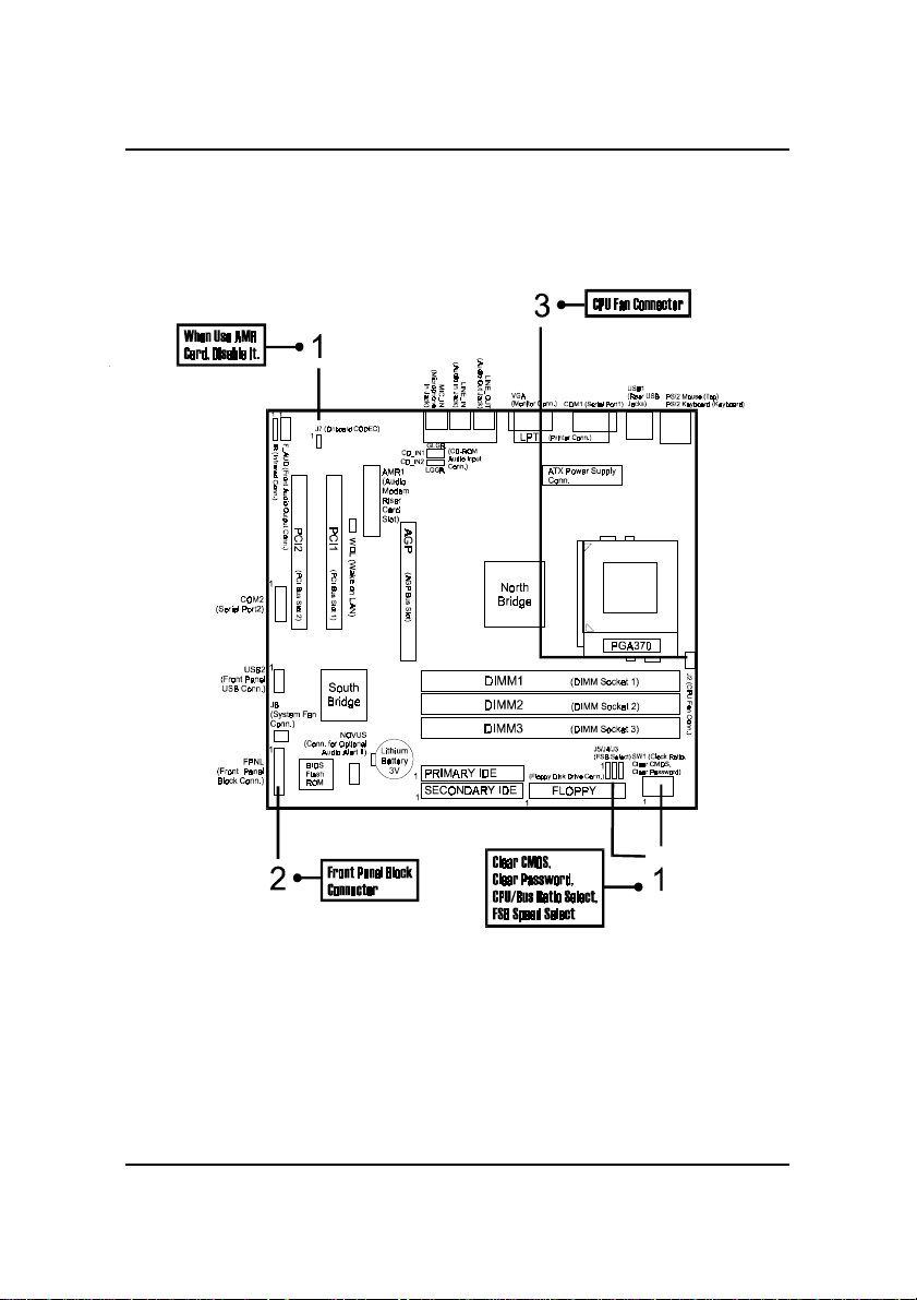
Mainboard Layout
4 - 2
Page 7
Quick Reference
1). CPU/BUS Speed Ratio Select, Clear CMOS,
Clear Password, Front Side Bus Speed Select,
AMR Card Function Enable
4 - 3
Page 8
FR31 Mainboard Manual
2). Front Panel Block Cable Connection
3). CPU Fan Installation
This connector is linked to the CPU fan. When the system is in S3 power saving mode,
the CPU fan will turn off; when it reverts back to full on mode, the fan will turn back
on.
Without suf ficient air circulation, the CPU may overheat resulting in dam-
age to both the CPU and the mainboard.
Damage may occur to the mainboard and/or the CPU fan if these pins are
used incorrectly. These are not jumpers, do not place jumper caps over these
pins.
4 - 4
Page 9

Overview
Chapter 1
Overview
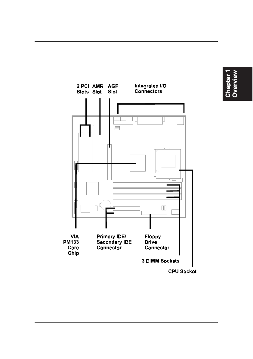
The Micro ATX, Socket 370 1stMainboard FR31 supports both the latest
generation Intel® and Cyrix processors. Intel’s new Celeron ™ PPGA/FCPGA and super fast Pentium FC-PGA Pentium®III processors are supported
with Front Side Bus speeds of 66 /100/133 MHz, while Cyrix III Processors are
supported at Front Side Bus speeds of 133 MHz.
The 1stMainboard FR31 is built around the new VIA PM133 chipset supporting both DVD and AGP 4x, thus ensuring photo-realistic 3D. Onboard AC97
sound ensures high quality audio, while providing the option of being disabled through the BIOS. Support for the Ultra DMA/100 protocol ensures for
high data transfer speeds especially for long sequential transfers required by
audio/visual applications. With 3 DIMM there is up to 1.5 GB available SDRAM
with further VC SDRAM support.
The 1stMainboard FR31 comes standard with the NOVUS range of innovative
features that assist in the installation and maintenance of your 1stMainboard.
The features include HotKey, which provides instant keyboard access to the
BIOS for adjustments to Clock and Default settings, LogoGenie, which allows
you to create your own customized logo to be displayed during system boot
up and BIOS Guardian, an Anti Virus utility that prevents viruses from dam-
aging your system BIOS. Clockometer is a user friendly Graphic User Interface that allows you to change clock speed settings directly, without having
to enter the BIOS Sub-Menus, while AudioAlert!, the World’ s first voice warn-
ing system for motherboards, warns you with an audio caution, if when booting no CPU, memory or VGA are detected.
Expansion is provided by 1 AGP, 2 PCI slots, and 1AMR. I/O connections
include 2 serial ports, 1 parallel port, 1 VGA port, 1 PS/2 mouse and keyboard
connector, 2 USB connectors, 2 front USB pin-headers and 1 media connector
( MIDI/Game Port, Line-In, Line-Out, Mic-In).
1 - 1
Page 10

FR31 Mainboard Manual
Package Checklist
If you discover any item below was damaged or lost, please contact your
vendor.
þ The mainboard þ This user manual
þ One FDD cable þ One HDD cable
þ One A T A/66 cable þ T wo software CDs (CD Pro, CD Plus)
þ Audio Alert I/II module
Front USB cable
Front Audio cable
One COM2 cable
(optional)
(optional)
(optional)
(optional)
1 - 2
Page 11
The FR31 Mainboard
Overview
1 - 3
Page 12

FR31 Mainboard Manual
Main Features
■ Easy Installation
||BIOS with support for Plug and Play , auto detection of IDE hard drives,
||LS-120|drives, IDE ZIP drives, Windows 95, W indows 98, Windows ME,
|Windows NT , Windows 2000, |and OS/2.
■ Leading Edge Chipset
VIA PM133 provides integrated DRAM controllers with new Dynamic
Power Management Architecture (DPMA), concurrent PCI, AGP 1.0/2.0
compliant and USB.
■ V ersatile Main Memory Support
Accepts up to 1.5GB DRAM using three DIMMs of 32, 64, 128, 256,
512MB with support for lightning-fast SDRAM (66/100/133MHz).
■ Flexible Processor Support
Onboard CPU socket supports:
Intel® Celeron PPGA/FCPGA 433/500/533/566/600/633/667/700/766MHz
at 66MHz FSB
Intel® CuMine FCPGA 500/550/600/650/700/750/800/850MHz at 100MHz
FSB
Intel® CuMine FCPGA 533/566/600/667/733/800/866/933MHz/1GHz at
133MHz FSB
Cyrix® III 533/600MHz at 133MHz FSB
Cyrix® III 550/600MHz at 100MHz FSB
■ PCI Expansion Slots, and AMR Slot
T wo 32-bit PCI Bus expansion slots provide the room to install a full range
of add-on cards, an AMR slot for audio-modem riser card.
1 - 4
Page 13

Overview
■ Compact Onboard Audio Subsystem
Embeded in VIA 686B, an integrated PCI-mastering dual full-duplex direct-sound AC97-link-compatible audio subsystem. Hardware sound
blaster pro and FM blocks are combined for MS Windows DOS box and
real mode DOS compatiblity . The loopback capability implemented for redirecting mixed audio streams into USB speakers for digital sound.
■ Onboard IrDA Connector
An IrDA connector for wireless infrared connections is available.
■■
■ Remote Wake-Up Support
■■
One LAN wake-up connector, WOL, supports LAN cards equipped for
remote wake-up functionality .
■■
■ Super Multi Input/Output (I/O) Support
■■
Integrated Plug and Play multi-I/O chipset features one high-speed UART
16550 compatible serial ports, one infrared port, one EPP/ECP capable
parallel port, and one FDD connector.
■■
■ USB Support
■■
Two USB jacks for rear panel connection and two front USB ports for
front panel connections provide you with convenient, high-speed Plug
and Play connections to the growing number of USB compliant external
peripheral devices on the market.
■ Enhanced PCI Bus Master IDE Controller with Ultra DMA/33 and
Ultra DMA/66/100 Support
Integrated Enhanced PCI Bus Master IDE controller features two dualchannel connectors that accept up to four Enhanced IDE devices, including CD-ROM and T ape Backup Drives, as well as Hard Disk Drives supporting the new Ultra DMA/66 protocol. Standard PIO Mode 3, PIO Mode
4, DMA Mode 2, DMA Mode 4, UltraDMA-100 Mode 5 devices are also
supported.
1 - 5
Page 14
FR31 Mainboard Manual
ACPI Ready
This mainboard fully implements the new ACPI (Advanced Configuration and
Power Interface) 1.0B Hardware and BIOS requirement. If you install ACPI
aware of operating system, such as Windows 98, you fully utilized the power
saving under ACPI. (Windows 2000 Professional supports ACPI functions.)
FIC Unique Innovation for Users (NOVUS) -
Enhanced Mainboard Features and System Support
■■
■ LogoGenie
■■
A user friendly GUI supporting Windows 95/98 (not W indows 2000/NT/
ME), LogoGenie allows you to customize, create or select a Logo which
will be displayed when the system is booting.
NOTE:
1. LogGenie supports Award BIOS only.
2. If you create a Logo file (.bmp) by LogoGenie, the file size must
||||be 640 x 464 x 256 colors.
T o enable this utility, please proceed as follows:
1 . Insert CD Pro (4.2 or above). Select LogoGenie from the Menu and
follow the installation instructions.
2 . After LogoGenie has been installed, go to Windows Start Box.
In Programs Menu, select LogoGenie 2.0, then select LogoGenie.
3 . Press F1 to read Help file to understand how to use this software if
it is new to you.
1 - 6
Page 15

Overview
WARNING: While excute Step3 below, please do not turn off the
sytsem power in order to avoid BIOS damage.
■■
■ BIOS Guardian
■■
BIOS Guardian by default is enabled. It must be disabled in order to
reflash BIOS, thus effectively acts as a fire-wall against viruses that can
attack the BIOS while the system is running.
BIOS Guardian can be disabled as follows:
1 . Go to BIOS Set Up Menu. (Press Del key while booting.)
2 . Go to Advanced BIOS Features Set Up Submenu.
3. Disable BIOS Guardian.
4. Save the setting, and restart system.
NOTE: However, if it is disabled and while boot the system, the
POST screen will be held and shows you the message to let you
know the current status of BIOS Guardian. To press G key will enable the BIOS Guardian again; or simply to press the space bar
will continue the booting process.
■■
■ Easy Key
■■
Instead of completing the multi-layered BIOS setup process these 3 Easy
Key functions provide direct access to Sub-Menu’s when completing
BIOS settings adjustments.
Easy-Keys are as follows:
Ctrl + c: T o enter clock settings menu.
Ctrl + p: To load Performance Default settings and restart.
Ctrl + f: T o load Fail-Safe Default settings and restart.
1 - 7
Page 16

FR31 Mainboard Manual
■■
■ Overclock Partner
■■
Should the system not start because clock speed settings have been
increased to a speed incompatible with the system, the Overclock Partner
allows you to reboot at system default settings, protecting hardware from
any damages.
Complete the following steps:
1. Turn the system off.
2 . Restart while holding down the Insert key. It is important that the
Insert key is held down until the default clock speed is shown on
the POST screen.
3 . Enter BIOS settings menu, and re-set clock speed desired or default.
■■
■ Clockometer
■■
Clockometer is a Windows 98 compatible, attractive and user friendly
Graphic User Interface (GUI). Clockometer enables you to change clock
speed settings directly, without having to enter the BIOS Sub-Menus.
With the on-screen display panel you can easily monitor your new clock
speed settings with gauges that identify your system speed, Front Side
Bus settings and CPU Ratios
On screen buttons:
1 . "+" and "-" buttons : adjust the Front Side Bus ( FSB )and CPU ratio.
( the 'hand' cursor means the active button)
2 . "OK" button : changes the FSB and CPU ratio (if adjustable) set-
tings right away . If you do not save your new setting, your system
will not implement the new setting when rebooting the next time.
3 . "SA VE" button : save your new settings for rebooting the computer .
4 . "Quit" button will escape the Clockometer program.
1 - 8
Page 17

Overview
■■
■ Aduio Alert I/II (optional)
■■
After complete a system upgrade, should the computer be assembled
incorrectly, a friendly onboard voice caution, will advice the error during
system boot up.
If you do not hear the Audio Alert, please check that your speakers are
connected.
Audio warning are activated as follows:
No CPU: ‘Caution! Processor not detected. Please check your PC’
No Memory: ‘Caution! Memory not detected. Please check your PC’
No Graphics: ‘Caution! VGA not detected. Please check your PC’
■■
■ Usage of Optional Aduio Alert II
■■
This mainboard came with an optional Audio Alert II daughter board. Audio
Alert II detects and provides an audio warning details for such components as
your CPU, VGA card and memory, while also monitoring your system clock
status. The complimentary software contained in the CD Pro enables you to
personalize these audio messages by recording new messages and saving
them to flash memory .
Installation
1. To install the Audio Alert II software, go to the Audio Alert II sub-directory
in the CD-Pro disc that came bundled with your PC.
2. Reboot the system.
3. From Start Icon click through to Audio Alert II Icon.
The Audio Alert II - Windows GUI will appear on your
screen
4. Audio Menu. Highlight to select Selection Control Panel
5. Selection Control Panel.
1 - 9
Page 18
FR31 Mainboard Manual
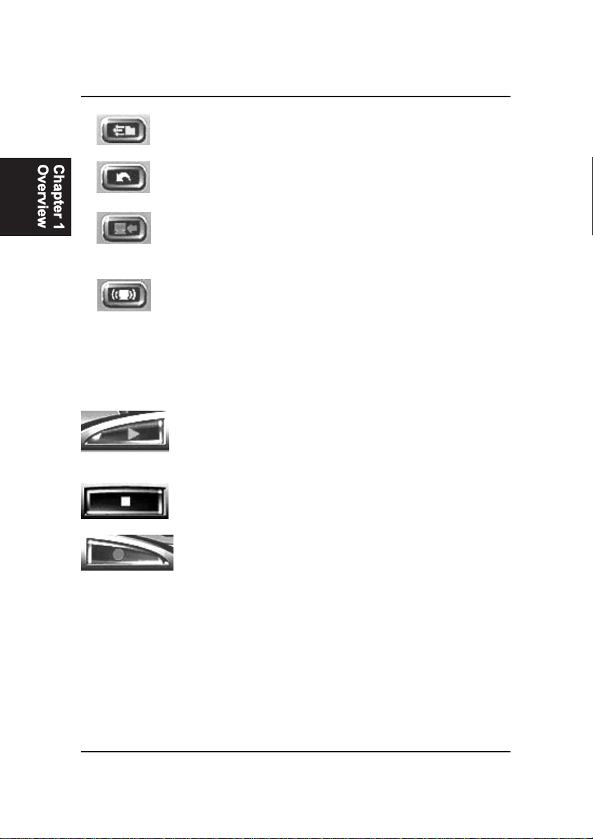
Language Select: Select default language -
Previous Message: Play the message previ-
Record to Flash-Memory:
Default Recording: Play back default message
6. Recording Control Panel
Play Button: Play message / your
English/Chinese/Janpanese
ously recorded
Press to update your own
recordings to flash-memory
recorded message as
highlighted
1 - 10
Stop Button: Stop playing message /
your recorded message
Record Button: Press to make your own
recorded message
Page 19

Overview
Example
1. You would like to replace the default CPU Detect message with your
own recording.
2. Select CPU Detect as per
3. Plug in a microphone to your MIC_IN jack.
4. Double Click the Record Button and make your voice recording.
5. Double Click the Stop Button when you have completed your record-
ing.
6. Double Click the Play Button to listen to your recording.
7. If you are satisfied with the recording you have made, click Record to
Flash-Memory Button, as per
record, repeat steps 4. to 6. in this example. (The re-flashing process
will take approx. 6 minutes.)
NOTE: Audio Alert II software utility only comes after CD Pro 4.3 if
you do not have program on your CD Pro, please go to FIC’s web
site to download the latest Audio Alert II utility.
4.
above.
5.
above, or if you would like to re-
1 - 11
Page 20

FR31 Mainboard Manual
This Page Left Blank for Note
1 - 12
Page 21

Installation Procedures
Chapter 2
Installation Procedures
The mainboard has several user-adjustable jumpers on the board that allow you to
configure your system to suit your requirements. This chapter contains information
on the various jumper settings on your mainboard.
To set up your computer, you must complete the following steps:
■ Step 1 - Set system jumpers/switches
■ Step 2 - Install memory modules
■ Step 3 - Install the Central Processing Unit (CPU)
■ Step 4 - Install expansion cards
■ Step 5 - Connect ribbon cables, cabinet wires, and power supply
■ Step 6 - Set up BIOS software
■ Step 7 - Install supporting software tools
WARNING: Excessive torque may damage the mainboard. When
using an electric screwdriver on the mainboard, make sure that
the torque is set to the allowable range of 5.0 ~ 8.0kg/cm.
Mainboard components contain very delicate Integrated Circuit
(IC) chips. To prevent static electricity from harming any of the
mainboard’s sensitive components, you should follow the
following precautions whenever working on the computer:
1. Unplug the computer when working on the inside.
2. Hold components by the edges and try not to touch the IC
||||chips, leads, or circuitry.
3. Wear an anti-static wrist strap which fits around the wrist.
4. Place components on a grounded anti-static pad or on the bag
that came with the component whenever the components are
separated from the system.
2 - 1
Page 22
FR31 Mainboard Manual
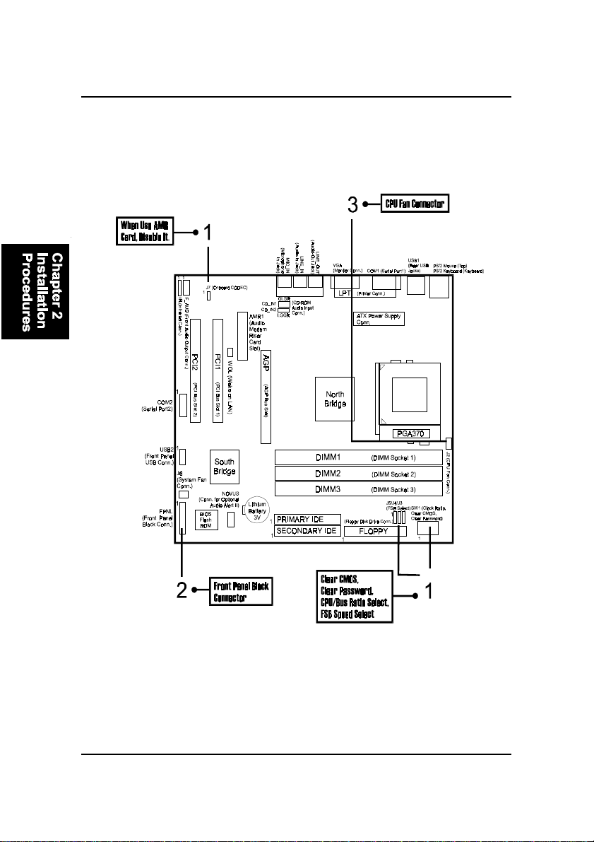
Quick Reference (from Page 2-2 to 2-4)
Mainboard Layout
2 - 2
Page 23
Installation Procedures
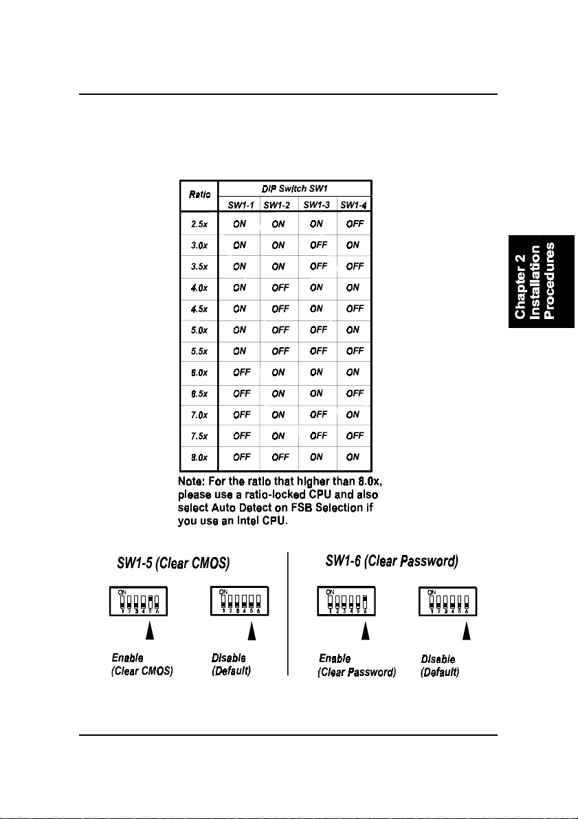
1). CPU/BUS Speed Ratio Select, Clear CMOS,
Clear Password, Front Side Bus Speed Select,
AMR Card Function Enable
2 - 3
Page 24
FR31 Mainboard Manual
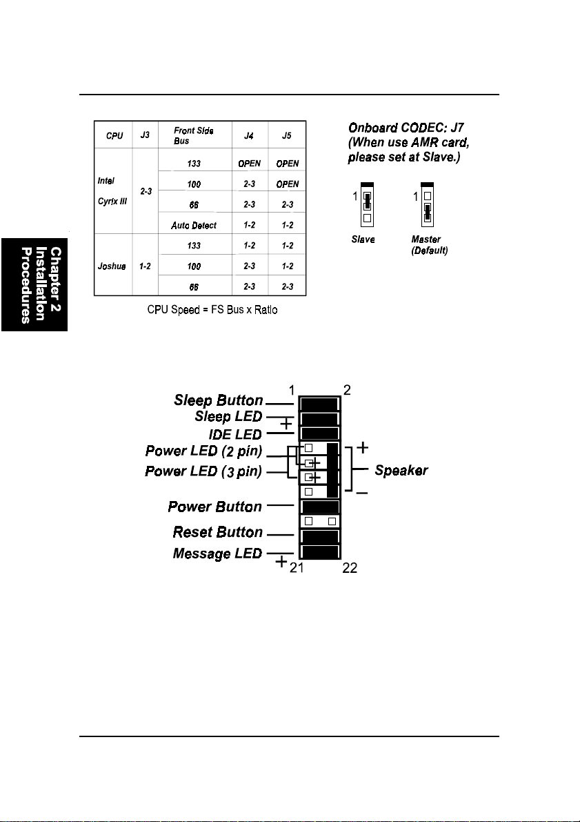
2). Front Panel Block Cable Connection
3). CPU Fan Installation
This connector is linked to the CPU fan. When the system is in S3 power saving mode,
the CPU fan will turn off; when it reverts back to full on mode, the fan will turn back
on.
Without suf ficient air circulation, the CPU may overheat resulting in dam-
age to both the CPU and the mainboard.
Damage may occur to the mainboard and/or the CPU fan if these pins are
used incorrectly. These are not jumpers, do not place jumper caps over these
pins.
2 - 4
Page 25
Installation Procedures
1). Set System Jumpers/Switches
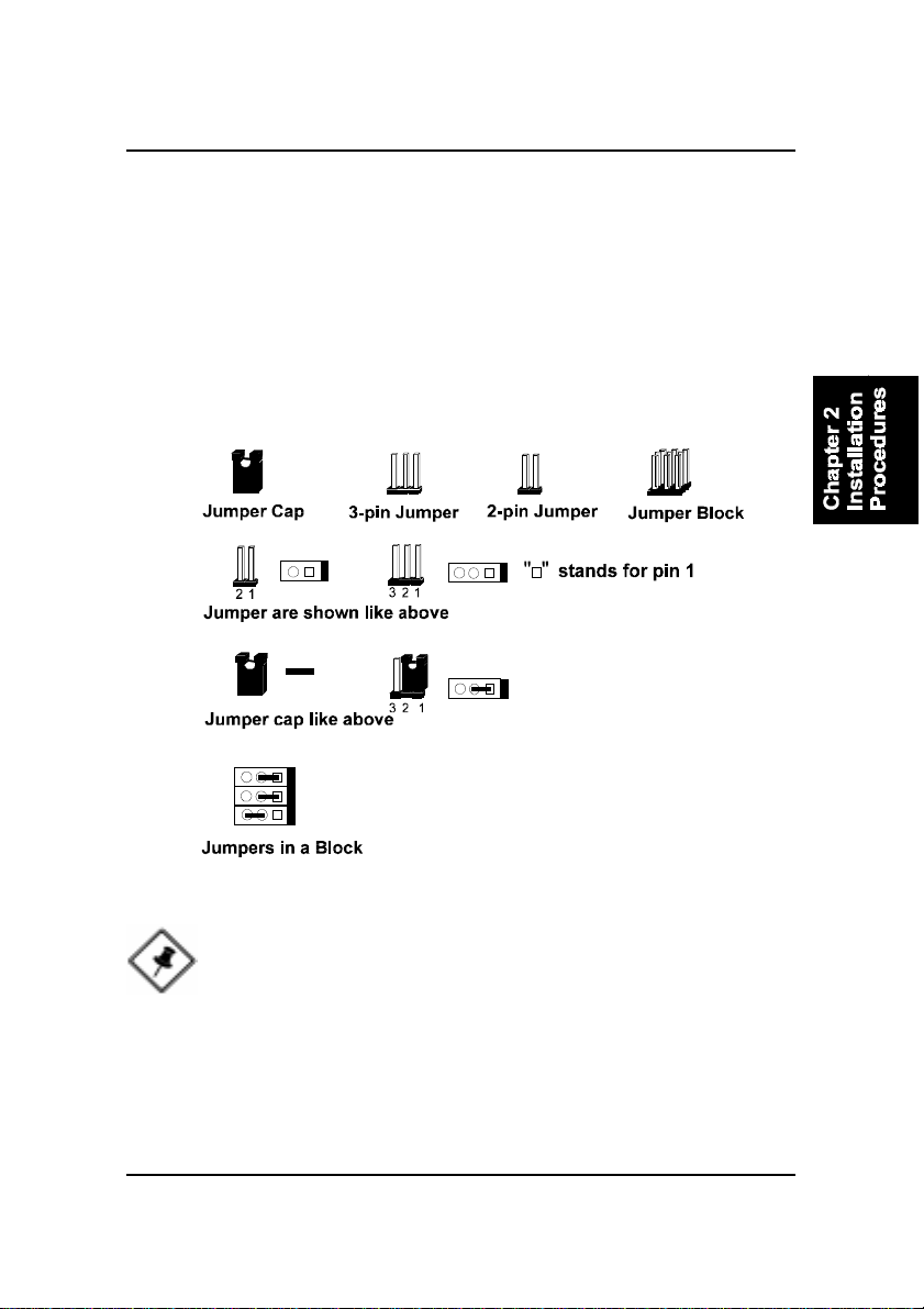
Jumpers are used to select the operation modes for your system. Some jumpers on the board have three metal pins with each pin representing a different
function. A “1” is written besides pin 1 on jumpers with three pins. To set a
jumper, a black cap containing metal contacts is placed over the jumper pin/s
according to the required configuration. A jumper is said to be shorted when
the black cap has been placed on one or two of its pins. The types of jumpers
used in this manual are shown below:
NOTE: Users are not encouraged to change the jumper settings
not listed in this manual. Changing the jumper settings improperly
may adversely affect system performance.
2 - 5
Page 26
FR31 Mainboard Manual
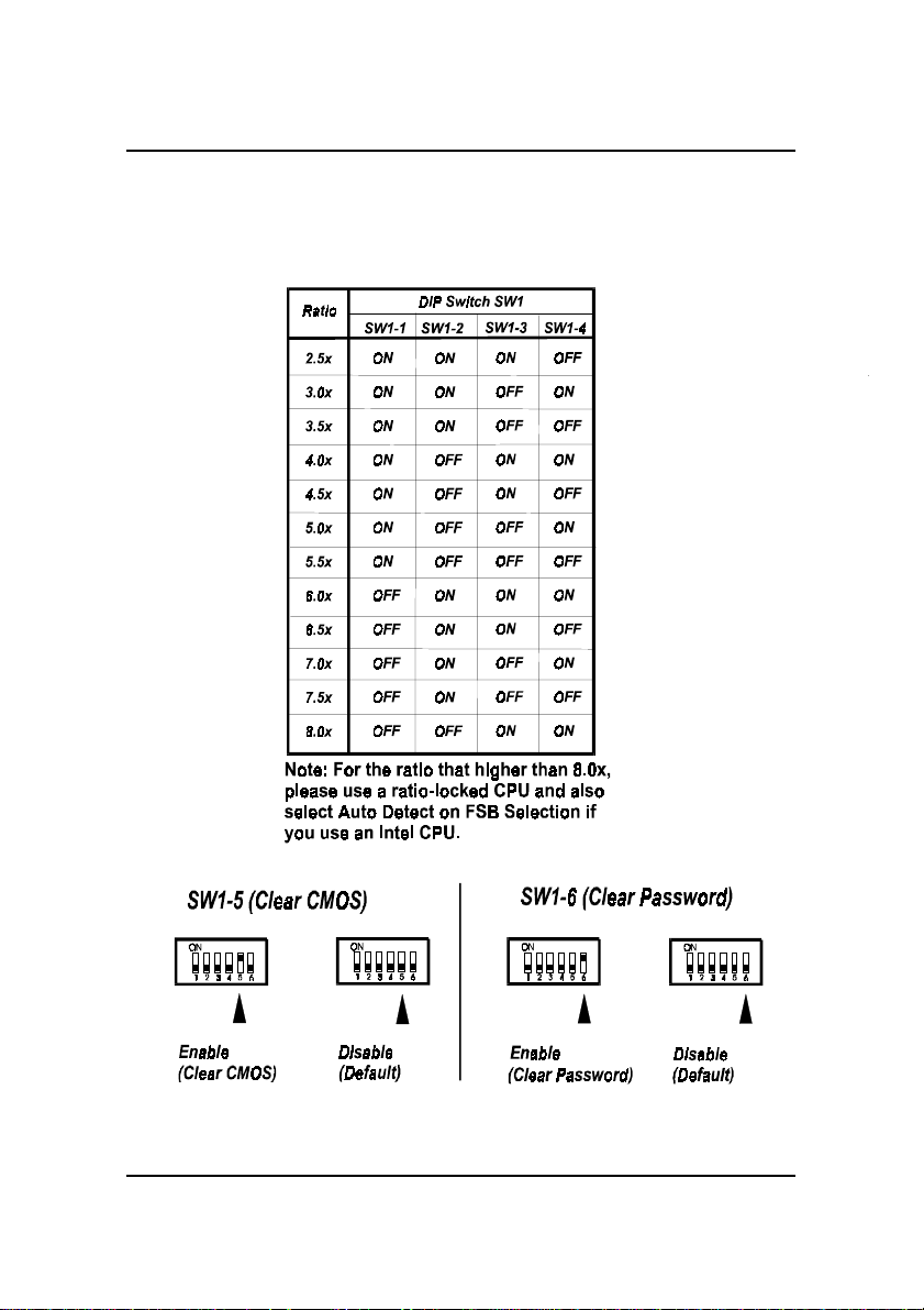
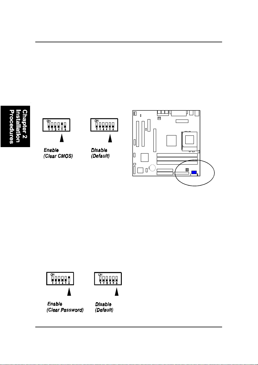
Clear CMOS: SW1-5
The CMOS RAM is powered by the onboard button cell battery. To clear the
RTC data: (1) T urn off your computer . (2) Move the CMOS Clear switch SW15 to “On” (Enabled). (3) Turn on your computer to display “CMOS checksum
error”. (4) Turn of f your computer. (5) Move the CMOS Clear switch SW1-5 to
“Off” (Disabled). (6) Turn on your computer. (7) Hold down the Delete key
when boots. (8) Enter the BIOS Setup to re-enter user preferences.
Clear Password: SW1-6
This switch allows you to enable or disable the password configuration. You
may need to enable this switch by moving it to the “On” (Enabled) position if
you forget your password. To clear the password setting: (1) Turn off your
computer. (2) Move the Clear Password switch SW1-6 to “On” (Enabled). (3)
Turn on your computer . (4) Hold down the Delete key during bootup and enter
BIOS Setup to re-enter user preferences. (5) Turn off your computer , (6) Move
the Clear Password switch SW1-6 to “Off” (Disabled). (7) Turn on your computer for the new settings to take effect.
2 - 6
Page 27
Installation Procedures
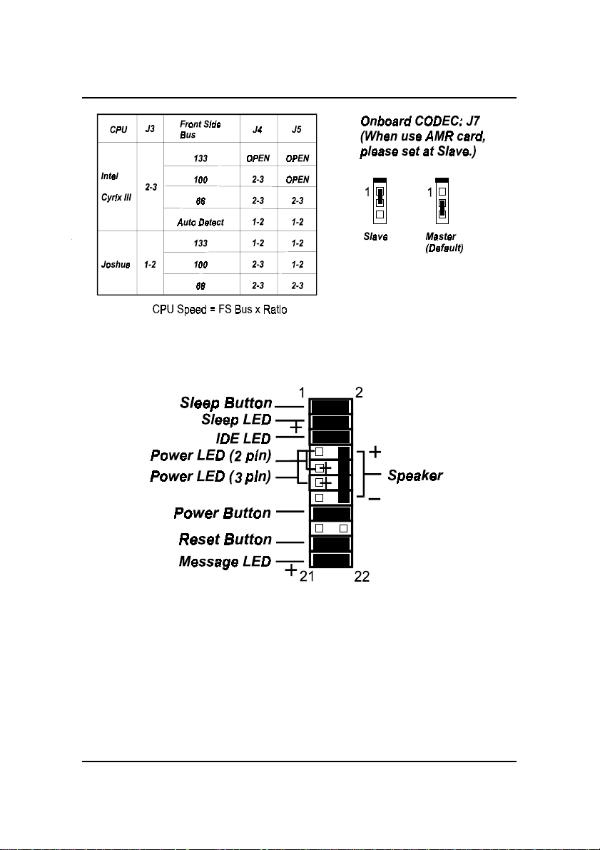
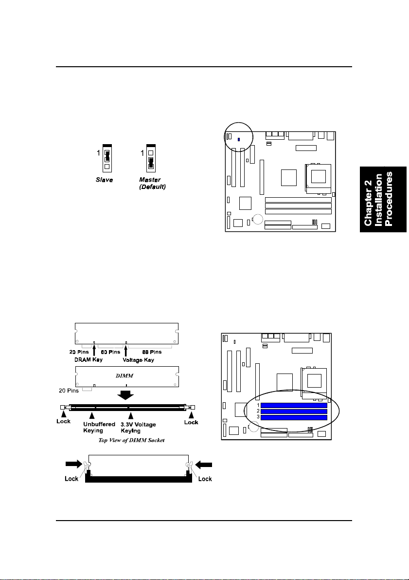
AMR Card Function Enable: J7
The jumper J7 is used when an AMR card is installed; please set this jumper at
1-2, Slave for the reason of onboard CODEC.
2). Install Memory Modules
1. Locate the DIMM slots on the mainboard.
2. Install the DIMM straight down into the DIMM slot using both hands.
3. The clip on both ends of the DIMM slot will close up to hold the DIMM
in place when the DIMM reaches the slot’s bottom.
Press the clips with both hands to remove the DIMM.
2 - 7
Page 28
FR31 Mainboard Manual
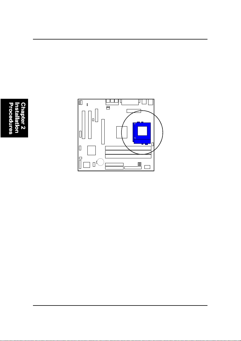
3). Install the CPU
The mainboard has built-in Switching Voltage Regulator to support CPU Vcore
autodetection. That is, It has the ability to detect and recognize the CPU
voltage, clock, ratio and enables users to set up the CPU frequency from the
BIOS Setup Screen. Users can adjust the frequency through “Frequency /
Voltage Control” of the BIOS Setup Screen.
T o install the CPU, do the following:
1 . Lift the lever on the side of the CPU socket.
2. Handle the chip by its edges and try not to touch any of the pins.
3 . Place the CPU in the socket. The chip has two notches to correctly locate
the chip. Align two notches of the processor with the two triangular
marks on the socket. Do not force the chip. The CPU should slide easily
into the socket.
4 . Swing the lever to the down position to lock the CPU in place.
5 . Place the cooling fan with heatsink on top of the installed CPU.
2 - 8
Page 29
Installation Procedures
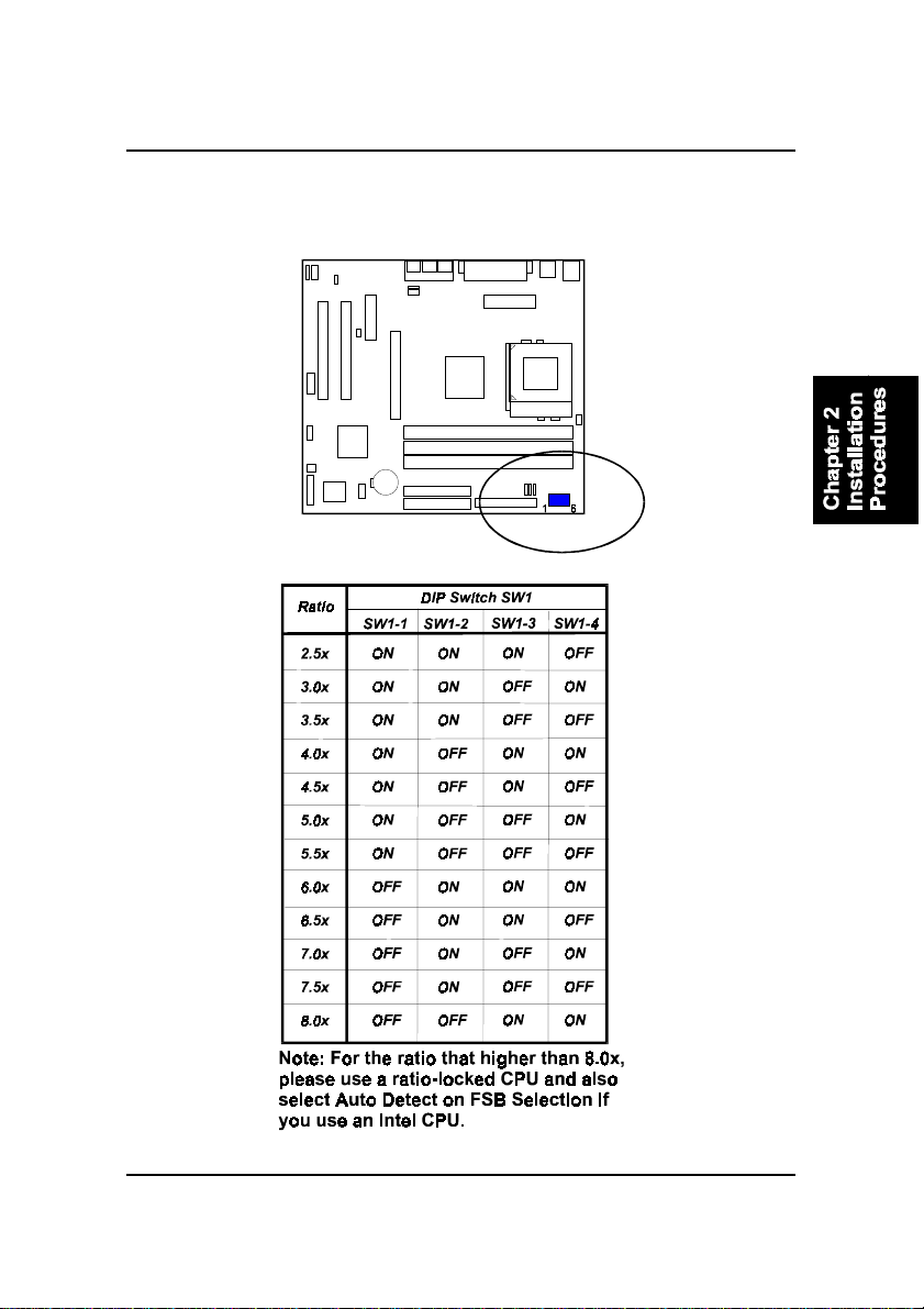
CPU/Bus Speed Ratio Select: SW1-1/2/3/4
The switch setting combination allow users to select the CPU/Bus speed ratio.
2 - 9
Page 30
FR31 Mainboard Manual
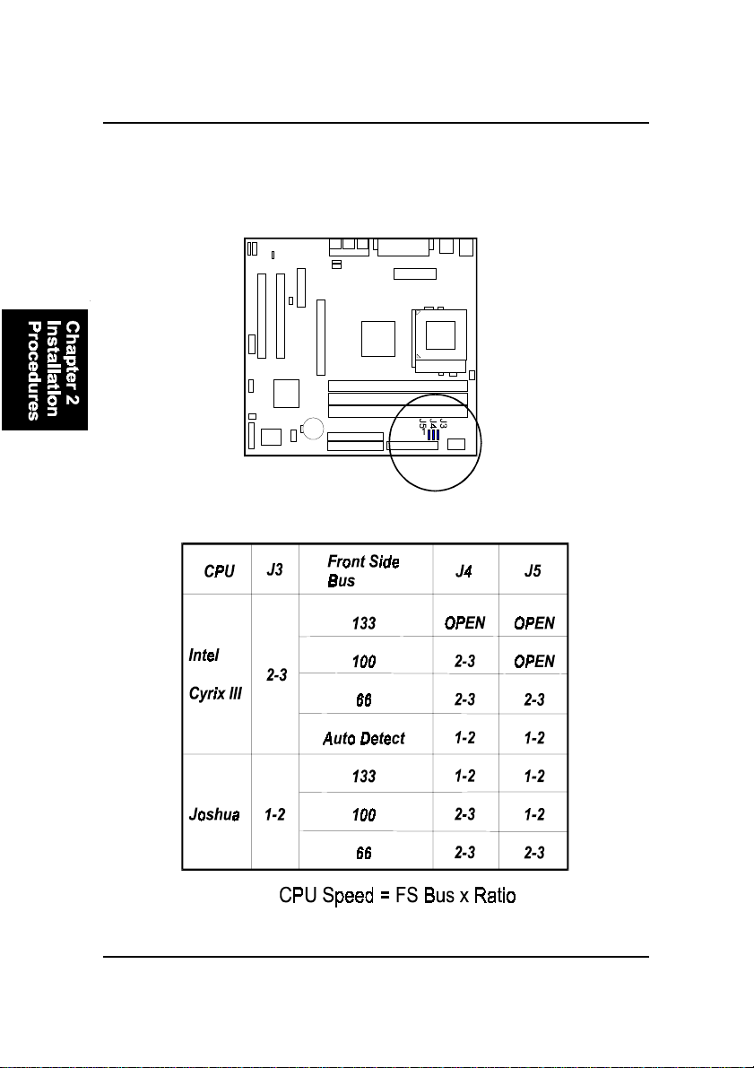
Front Side Bus Speed Select: J3/J4/J5
The three jumpers, in a combination way, allow you to select the FSB speed
according to the table below .
2 - 10
Page 31
Installation Procedures
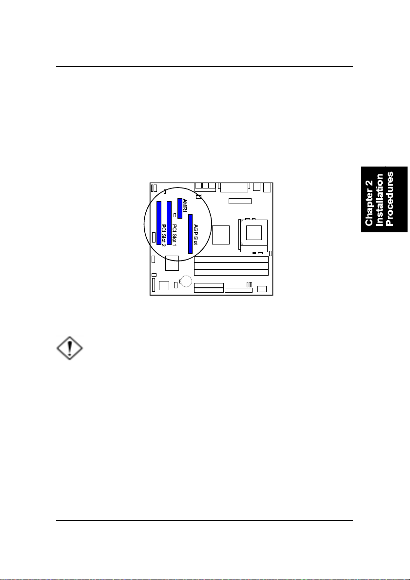
4). Install Expansion Cards
This section describes how to connect an expansion card to one of your
system’s expansion slots. Expansion cards are printed circuit boards that,
when connected to the mainboard, increase the capabilities of your system.
For example, expansion cards can provide video and sound capabilities. The
mainboard features one AMR (audio-modem riser), one AGP , and two PCI bus
expansion slots.
CAUTION: Make sure to unplug the power supply when adding or
removing expansion cards or other system components. Failure to
do so may cause severe damage to both the mainboard and
expansioncards.
Always observe static electricity precautions.
Please read “Handling Precautions” at the start of this manual.
T o install an expansion card, follow the steps below:
1. Remove the computer chassis cover and select an empty expansion
slot.
2. Remove the corresponding slot cover from the computer chassis.
Unscrew the mounting screw that secures the slot cover and pull
the slot cover out from the computer chassis. Keep the slot cover
mounting screw nearby.
2 - 11
Page 32
FR31 Mainboard Manual
3 . Holding the edge of the peripheral card, carefully align the edge
connector with the expansion slot.
4. Push the card firmly into the slot. Push down on one end of the
expansion card, then the other. Use this “rocking” motion until the
add–on card is firmly seated inside the expansion slot.
5. Secure the board with the mounting screw removed in Step 2. Make
sure that the card has been placed evenly and completely into the
expansion slot.
6 . Replace the computer system’s cover.
7 . Setup the BIOS if necessary .
8. Install the necessary software drivers for the expansion card.
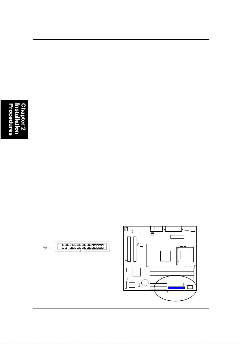
5). Connect Devices
Floppy Diskette Drive Connector: FLOPPY
This connector provides the connection with your floppy disk drive.
The red stripe of the ribbon cable must be the same side with the Pin 1.
2 - 12
Page 33
Installation Procedures
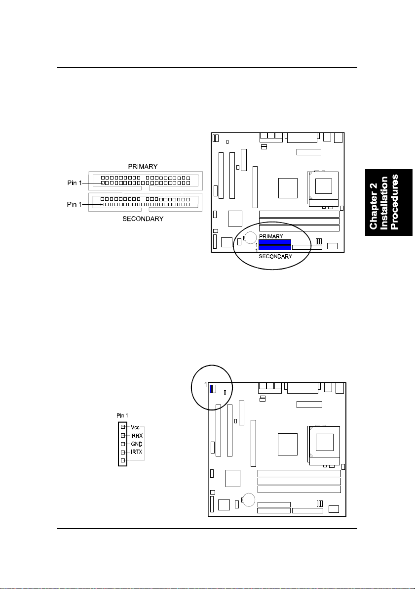
IDE Device Connectors: PRIMARY, SECONDARY
These two connectors are used for your IDE hard disk drives, CD drives, LS120|drives, or IDE ZIP drives. The red stripe of the ribbon cable must be the
same side with the Pin 1.
Infrared Connector: IR
This 5-pin connector is used to link with your IR device to allow transmission
of data to another system that also supports the IR feature. This module
mounts to a small opening on system cases that support it.
2 - 13
Page 34
FR31 Mainboard Manual
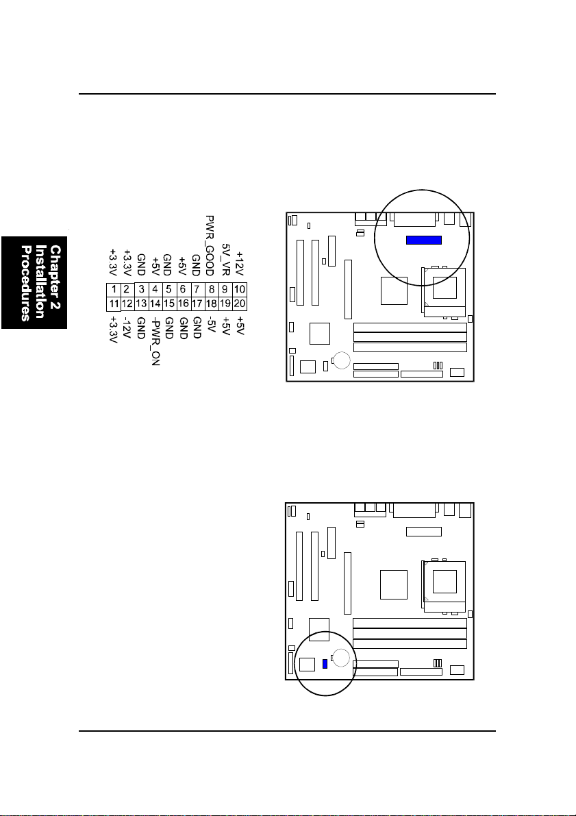
ATX Power Connector: POWER
This 20-pin male block connector is connected to the A TX power supply. The
plug from the power supply will only insert in one orientation because of the
different hole sizes. Find the proper orientation and push down firmly making
sure that the pins are aligned.
Optional Audio Alert II Module Connector: NOVUS
The connector provides you with the linkages of optional Audio Alert II
module.
2 - 14
Page 35
Installation Procedures
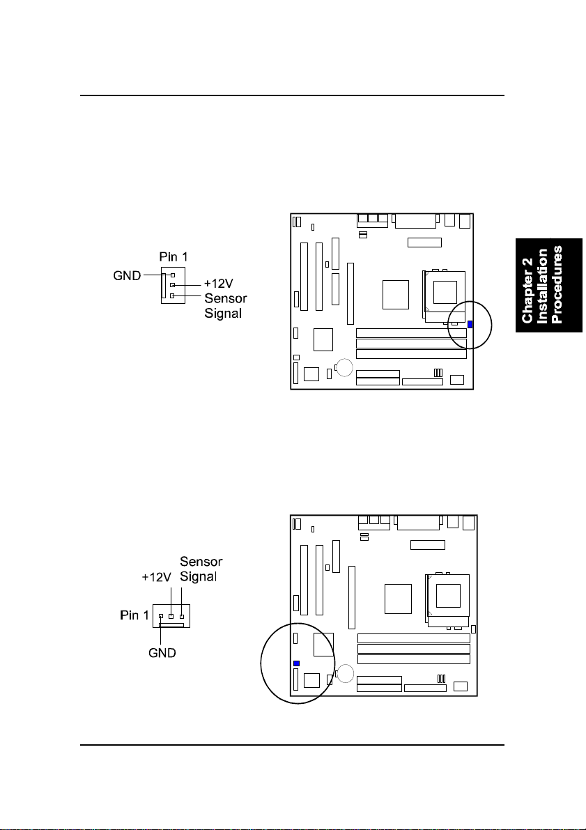
CPU Fan Connector: J2
This connector is linked to the CPU fan. When the system is in S3 suspend
mode, the CPU fan will turn off; when it reverts back to full–on mode, the fan
will turn back on. Please refer to the CPU fan installation manual for more
information.
System Case Fan Connector: J6
The 3-pin connector allows you to link with the cooling fan on the system case
to lower the system temperature.
2 - 15
Page 36
FR31 Mainboard Manual
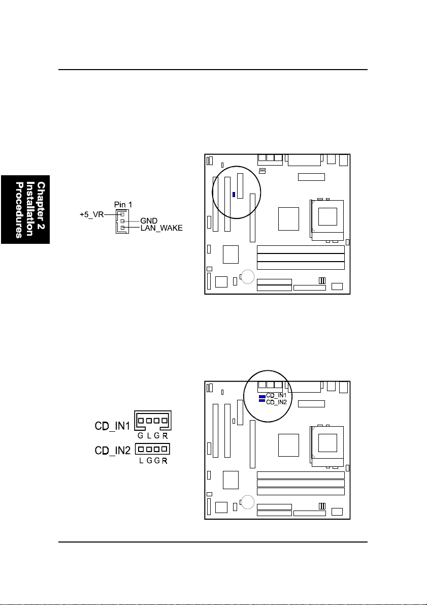
Wake-On-Lan Connector: WOL
This 3-pin connector allows the remote servers to manage the system that
installed this mainboard via your network adapter which also supports WOL.
When you install such a LAN card, please read its installation guide for more
information.
CD Audio-In Connectors: CD_IN1, CD_IN2
The CD_IN1/2 connectors are used for different types for CD drive audio in
port.
2 - 16
Page 37
Installation Procedures
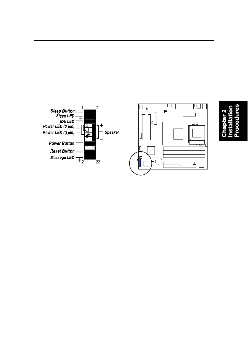
Front Panel Block Connector: FPNL
This block connector includes the connectors for linking with IDE LED, power
LED, sleep LED, power button, message LED, sleep button, reset button and
speaker on the front panel of the system case. Please identify polarities of plug
wires for the case speaker and LEDs. Please ask vendor about this information
when you buy them and install the system by yourself. The plug wires polarities of these buttons will not affect the function.
Message LED is connected with the message LED. When the system is running normally, the indicator is of f. It is controlled by the operating system or
application software.
Reset Button is connected to the reset button. Push this switch to reboot the
system instead of turning the power button off and on.
Power Button is connected with power button. Push this switch allows the
system to be turned on and off rather than using the power supply button.
Power LED is connected with the system power indicator to indicate whether
the system is on/off. It will blink when the system enters suspend mode.
Speaker is connected with the case speaker.
IDE LED is connected to the IDE device indicator. This LED will blink when
the hard disk drives are activated.
Sleep LED is connected with sleep mode indicator.
Sleep Button is connected with sleep button. T o enter the system into power
saving mode, simply press this button when the system is in full-on mode.
2 - 17
Page 38
FR31 Mainboard Manual
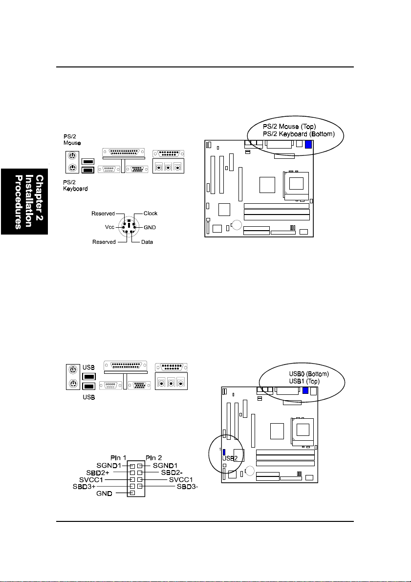
PS/2 Keyboard and Mouse Connector: KB, MS
These two 6-pin female (PS/2 keyboard is purple color and PS/2 mouse is
green color) connectors are used for your PS/2 keyboard and PS/2 mouse.
Universal Serial Bus Connectors: Rear USBs, Front USBs
These two black connectors integrated on the edge of the board are used for
linking with USB peripheral devices. This board also provides a connector
USB2 for linking with the two USB sockets on the front panel of some system
cases. Please note your operating system must support USB features, such as
MS Windows 98, MS W indows 95 OSR2.5 with USB Supplement.
The figure below is the pin assignment
of the USB2 connector for two front panel
USB connections.
2 - 18
Page 39
Installation Procedures
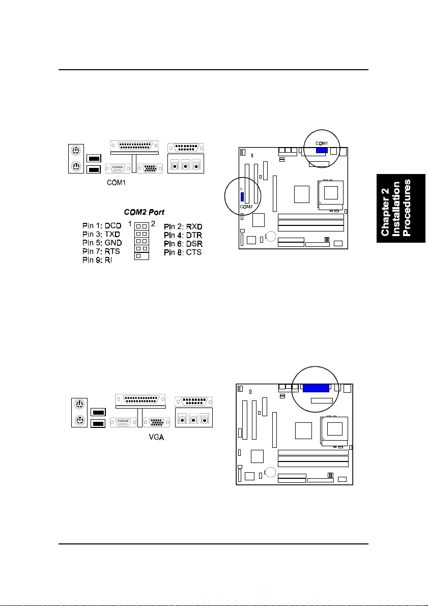
Serial Port Connectors: COM1, COM2
COM1 (9-pin D-sub male connector with teal color) and COM2 (9-pin male
connector) allow you to connect with your devices that use serial ports, such
as a serial mouse or an external modem.
Video Graphics Accelerator Connector: VGA
This 15-pin female D-sub blue connector is connected to your display monitor.
2 - 19
Page 40
FR31 Mainboard Manual
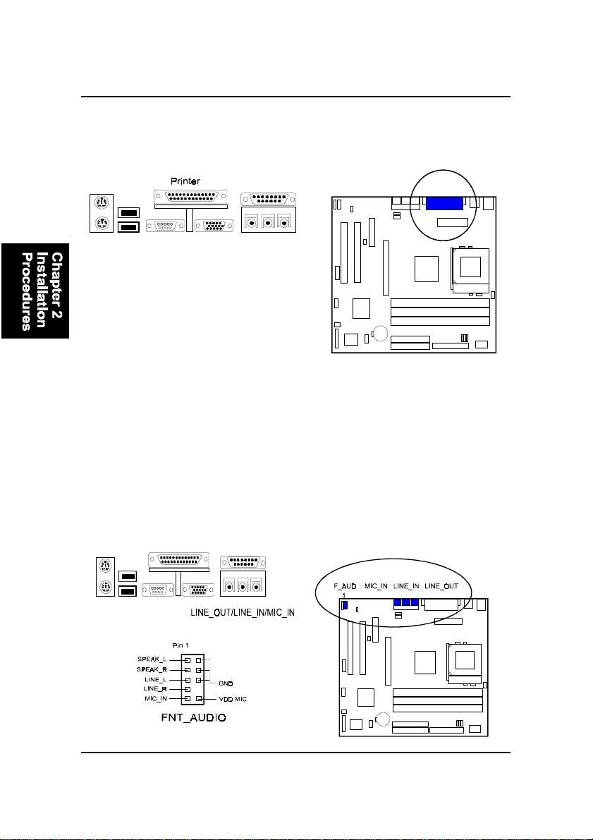
Printer Connector: LPT
This 25-pin D-Sub female burgundy-colored connector is attached to your
printer.
Audio I/O Jacks: LINE_OUT, LINE_IN, MIC_IN,
FNT_AUDIO
LINE_OUT (lime) can be connected to headphones or preferably powered
speakers. LINE_IN (light blue) allows tape players or other audio sources to
be recorded by your computer or played through the LINE_OUT. MIC_IN
(pink) allows microphones to be connected for voice input. The mainboard
also provides you with a front panel audio port connector, FNT_AUDIO,
when needed. Its pin definitions were presented below .
2 - 20
Page 41
Installation Procedures
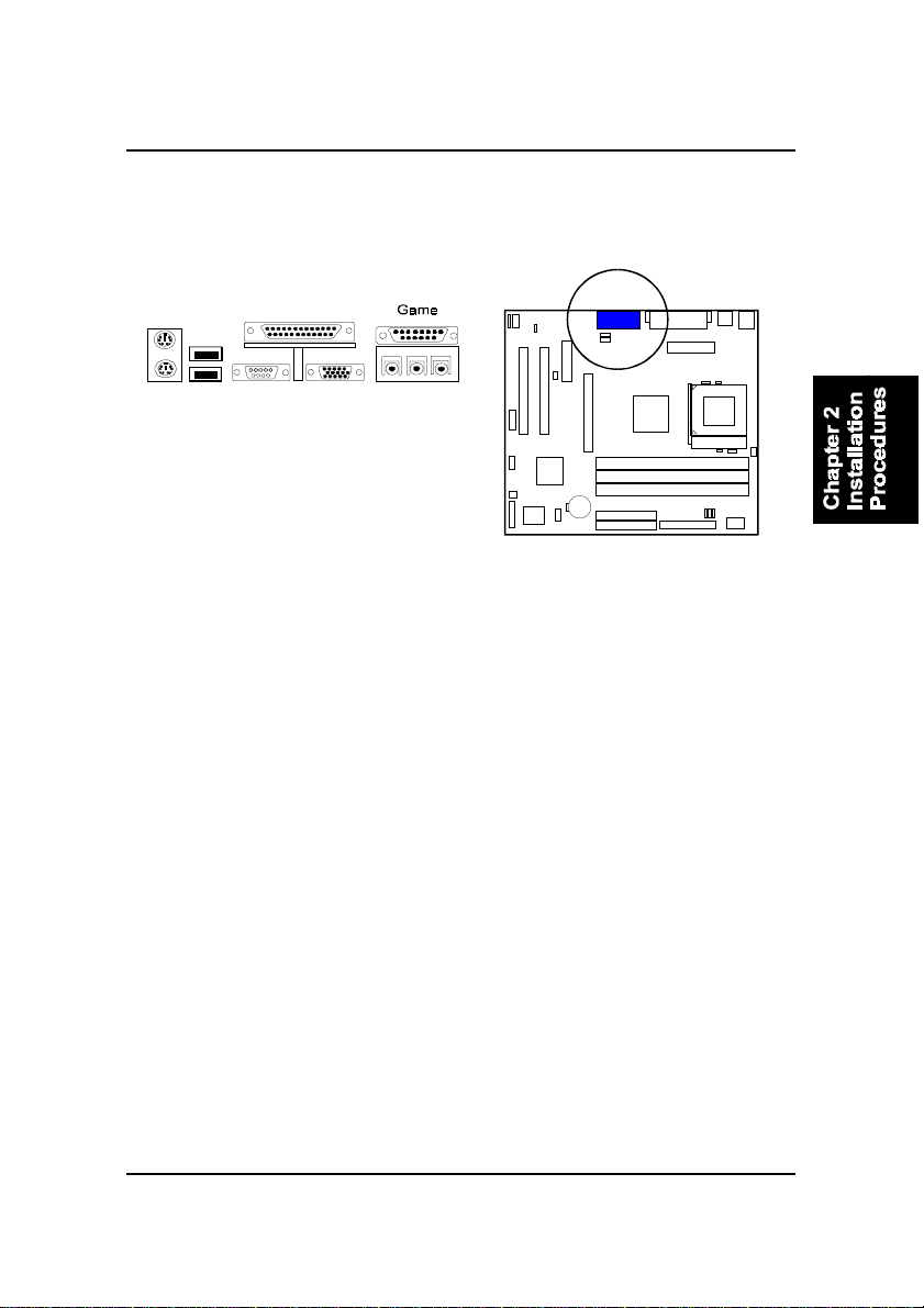
Game/MIDI Connector: GAME
This 15-pin female gold-colored connector allows you to connect game joysticks or game pads. Connect MIDI devices for playing or editing audio.
2 - 21
Page 42

FR31 Mainboard Manual
This Page Left Blank for Note
2 - 22
Page 43

Installation Procedures
Chapter 2
Installation Procedures
The mainboard has several user-adjustable jumpers on the board that allow you to
configure your system to suit your requirements. This chapter contains information
on the various jumper settings on your mainboard.
To set up your computer, you must complete the following steps:
■ Step 1 - Set system jumpers/switches
■ Step 2 - Install memory modules
■ Step 3 - Install the Central Processing Unit (CPU)
■ Step 4 - Install expansion cards
■ Step 5 - Connect ribbon cables, cabinet wires, and power supply
■ Step 6 - Set up BIOS software
■ Step 7 - Install supporting software tools
WARNING: Excessive torque may damage the mainboard. When
using an electric screwdriver on the mainboard, make sure that
the torque is set to the allowable range of 5.0 ~ 8.0kg/cm.
Mainboard components contain very delicate Integrated Circuit
(IC) chips. To prevent static electricity from harming any of the
mainboard’s sensitive components, you should follow the
following precautions whenever working on the computer:
1. Unplug the computer when working on the inside.
2. Hold components by the edges and try not to touch the IC
||||chips, leads, or circuitry.
3. Wear an anti-static wrist strap which fits around the wrist.
4. Place components on a grounded anti-static pad or on the bag
that came with the component whenever the components are
separated from the system.
2 - 1
Page 44
FR31 Mainboard Manual
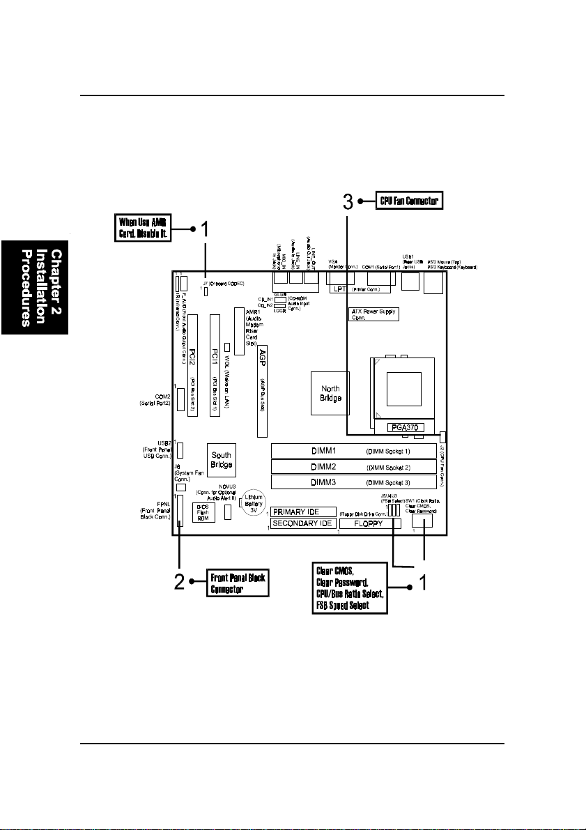
Quick Reference (from Page 2-2 to 2-4)
Mainboard Layout
2 - 2
Page 45
Installation Procedures
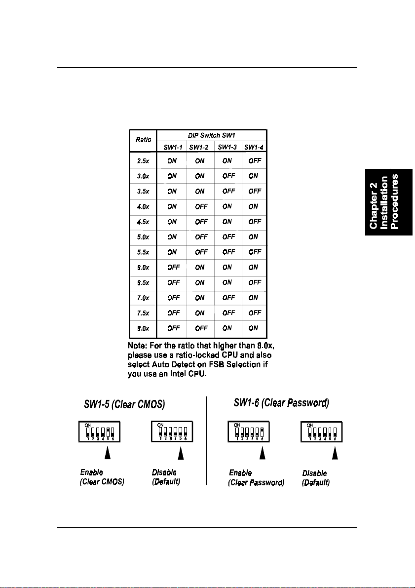
1). CPU/BUS Speed Ratio Select, Clear CMOS,
Clear Password, Front Side Bus Speed Select,
AMR Card Function Enable
2 - 3
Page 46
FR31 Mainboard Manual
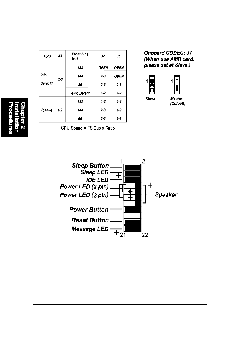
2). Front Panel Block Cable Connection
3). CPU Fan Installation
This connector is linked to the CPU fan. When the system is in S3 power saving mode,
the CPU fan will turn off; when it reverts back to full on mode, the fan will turn back
on.
Without suf ficient air circulation, the CPU may overheat resulting in dam-
age to both the CPU and the mainboard.
Damage may occur to the mainboard and/or the CPU fan if these pins are
used incorrectly. These are not jumpers, do not place jumper caps over these
pins.
2 - 4
Page 47
Installation Procedures
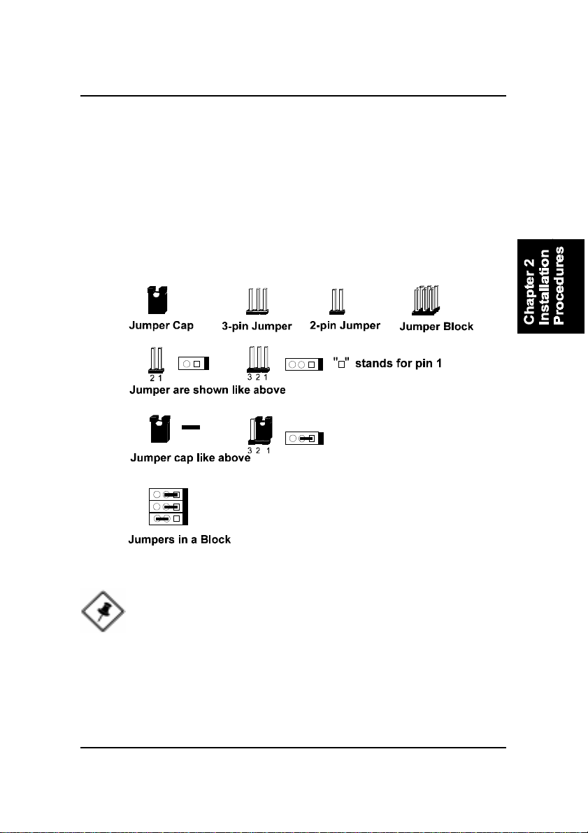
1). Set System Jumpers/Switches
Jumpers are used to select the operation modes for your system. Some jumpers on the board have three metal pins with each pin representing a different
function. A “1” is written besides pin 1 on jumpers with three pins. To set a
jumper, a black cap containing metal contacts is placed over the jumper pin/s
according to the required configuration. A jumper is said to be shorted when
the black cap has been placed on one or two of its pins. The types of jumpers
used in this manual are shown below:
NOTE: Users are not encouraged to change the jumper settings
not listed in this manual. Changing the jumper settings improperly
may adversely affect system performance.
2 - 5
Page 48
FR31 Mainboard Manual
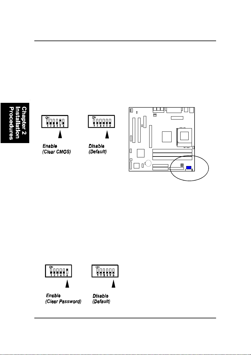
Clear CMOS: SW1-5
The CMOS RAM is powered by the onboard button cell battery. To clear the
RTC data: (1) T urn off your computer . (2) Move the CMOS Clear switch SW15 to “On” (Enabled). (3) Turn on your computer to display “CMOS checksum
error”. (4) Turn of f your computer. (5) Move the CMOS Clear switch SW1-5 to
“Off” (Disabled). (6) Turn on your computer. (7) Hold down the Delete key
when boots. (8) Enter the BIOS Setup to re-enter user preferences.
Clear Password: SW1-6
This switch allows you to enable or disable the password configuration. You
may need to enable this switch by moving it to the “On” (Enabled) position if
you forget your password. To clear the password setting: (1) Turn off your
computer. (2) Move the Clear Password switch SW1-6 to “On” (Enabled). (3)
Turn on your computer . (4) Hold down the Delete key during bootup and enter
BIOS Setup to re-enter user preferences. (5) Turn off your computer , (6) Move
the Clear Password switch SW1-6 to “Off” (Disabled). (7) Turn on your computer for the new settings to take effect.
2 - 6
Page 49
Installation Procedures
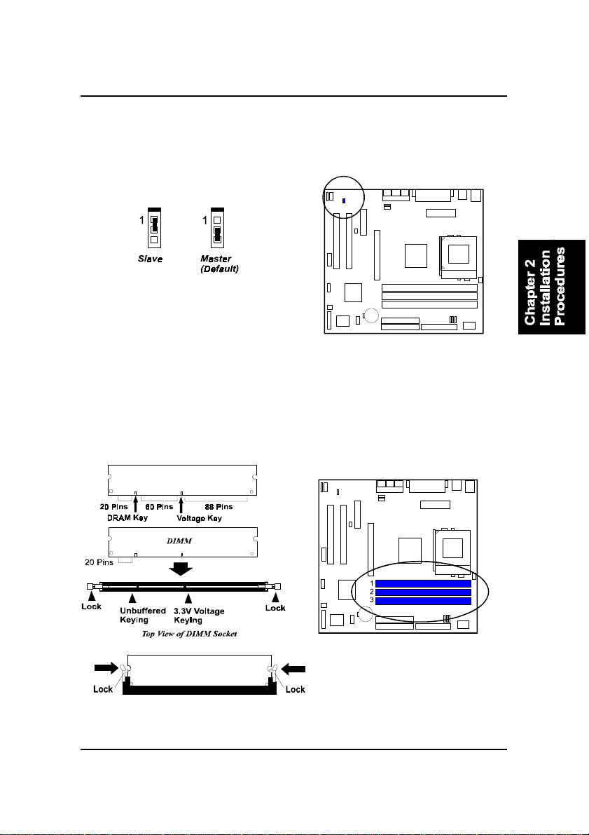
AMR Card Function Enable: J7
The jumper J7 is used when an AMR card is installed; please set this jumper at
1-2, Slave for the reason of onboard CODEC.
2). Install Memory Modules
1. Locate the DIMM slots on the mainboard.
2. Install the DIMM straight down into the DIMM slot using both hands.
3. The clip on both ends of the DIMM slot will close up to hold the DIMM
in place when the DIMM reaches the slot’s bottom.
Press the clips with both hands to remove the DIMM.
2 - 7
Page 50
FR31 Mainboard Manual
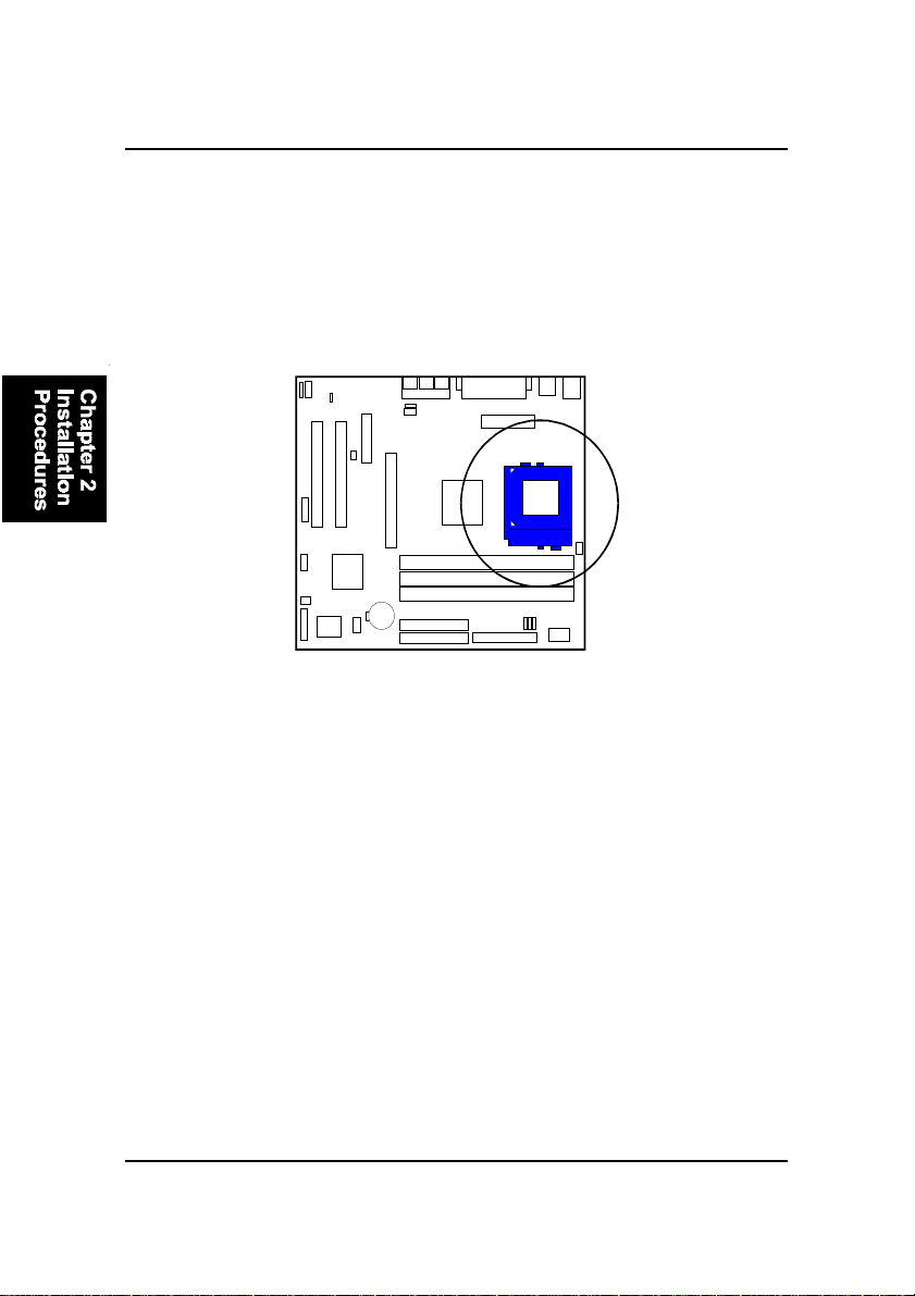
3). Install the CPU
The mainboard has built-in Switching Voltage Regulator to support CPU Vcore
autodetection. That is, It has the ability to detect and recognize the CPU
voltage, clock, ratio and enables users to set up the CPU frequency from the
BIOS Setup Screen. Users can adjust the frequency through “Frequency /
Voltage Control” of the BIOS Setup Screen.
T o install the CPU, do the following:
1 . Lift the lever on the side of the CPU socket.
2. Handle the chip by its edges and try not to touch any of the pins.
3 . Place the CPU in the socket. The chip has two notches to correctly locate
the chip. Align two notches of the processor with the two triangular
marks on the socket. Do not force the chip. The CPU should slide easily
into the socket.
4 . Swing the lever to the down position to lock the CPU in place.
5 . Place the cooling fan with heatsink on top of the installed CPU.
2 - 8
Page 51
Installation Procedures
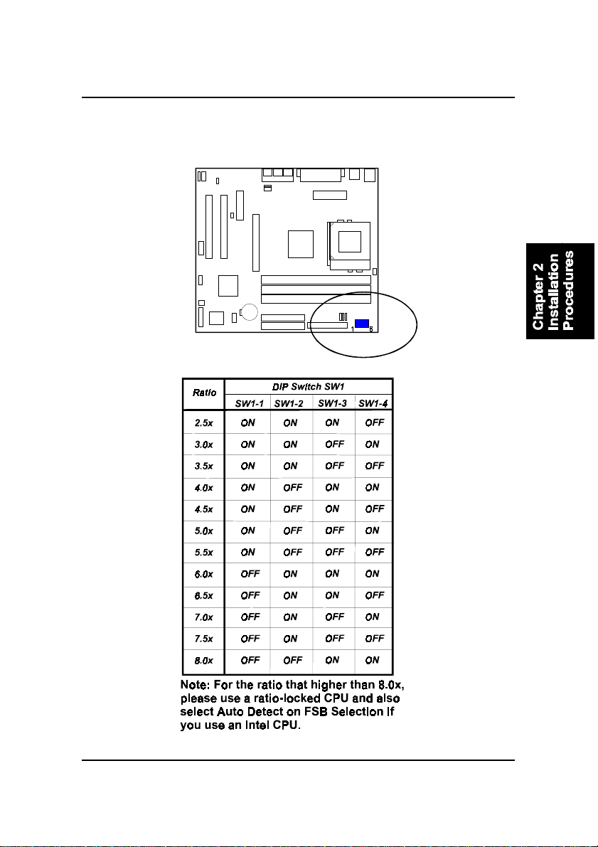
CPU/Bus Speed Ratio Select: SW1-1/2/3/4
The switch setting combination allow users to select the CPU/Bus speed ratio.
2 - 9
Page 52
FR31 Mainboard Manual
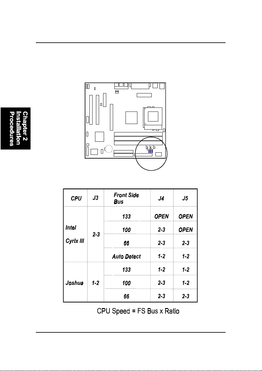
Front Side Bus Speed Select: J3/J4/J5
The three jumpers, in a combination way, allow you to select the FSB speed
according to the table below .
2 - 10
Page 53
Installation Procedures
4). Install Expansion Cards
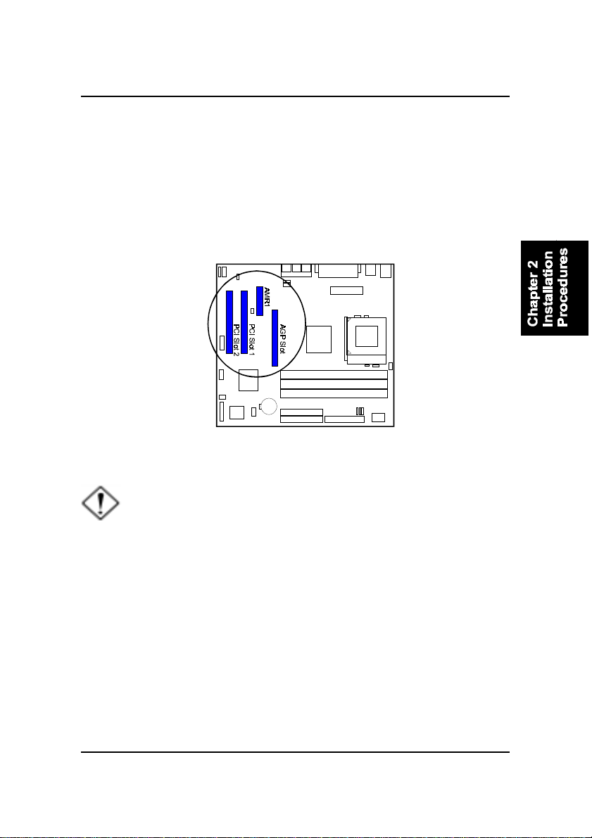
This section describes how to connect an expansion card to one of your
system’s expansion slots. Expansion cards are printed circuit boards that,
when connected to the mainboard, increase the capabilities of your system.
For example, expansion cards can provide video and sound capabilities. The
mainboard features one AMR (audio-modem riser), one AGP , and two PCI bus
expansion slots.
CAUTION: Make sure to unplug the power supply when adding or
removing expansion cards or other system components. Failure to
do so may cause severe damage to both the mainboard and
expansioncards.
Always observe static electricity precautions.
Please read “Handling Precautions” at the start of this manual.
T o install an expansion card, follow the steps below:
1. Remove the computer chassis cover and select an empty expansion
slot.
2. Remove the corresponding slot cover from the computer chassis.
Unscrew the mounting screw that secures the slot cover and pull
the slot cover out from the computer chassis. Keep the slot cover
mounting screw nearby.
2 - 11
Page 54
FR31 Mainboard Manual
3 . Holding the edge of the peripheral card, carefully align the edge
connector with the expansion slot.
4. Push the card firmly into the slot. Push down on one end of the
expansion card, then the other. Use this “rocking” motion until the
add–on card is firmly seated inside the expansion slot.
5. Secure the board with the mounting screw removed in Step 2. Make
sure that the card has been placed evenly and completely into the
expansion slot.
6 . Replace the computer system’s cover.
7 . Setup the BIOS if necessary .
8. Install the necessary software drivers for the expansion card.
5). Connect Devices
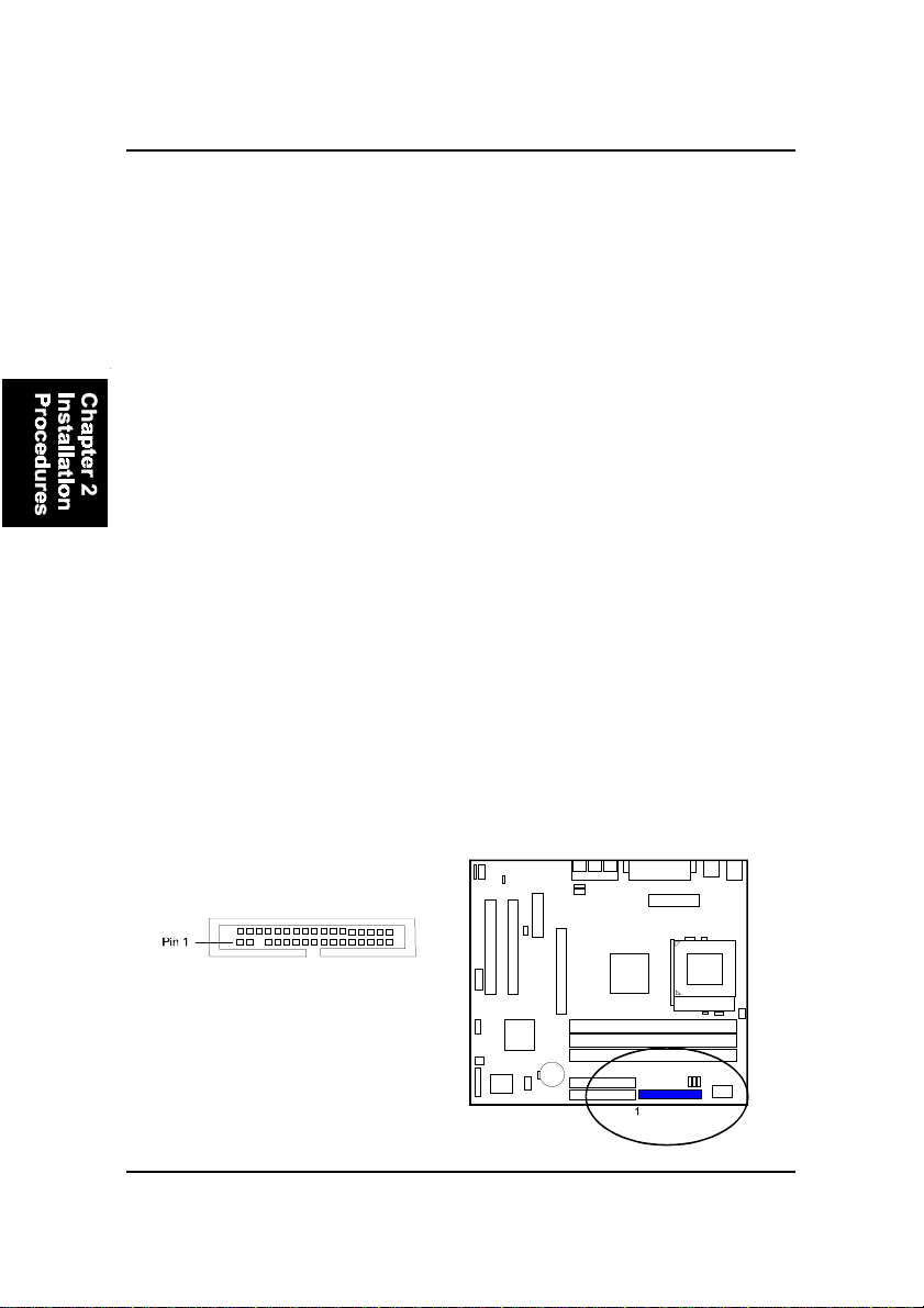
Floppy Diskette Drive Connector: FLOPPY
This connector provides the connection with your floppy disk drive.
The red stripe of the ribbon cable must be the same side with the Pin 1.
2 - 12
Page 55
Installation Procedures
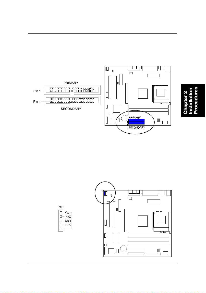
IDE Device Connectors: PRIMARY, SECONDARY
These two connectors are used for your IDE hard disk drives, CD drives, LS120|drives, or IDE ZIP drives. The red stripe of the ribbon cable must be the
same side with the Pin 1.
Infrared Connector: IR
This 5-pin connector is used to link with your IR device to allow transmission
of data to another system that also supports the IR feature. This module
mounts to a small opening on system cases that support it.
2 - 13
Page 56
FR31 Mainboard Manual
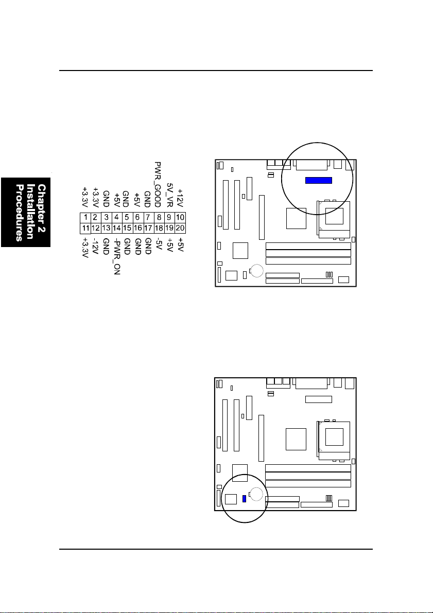
ATX Power Connector: POWER
This 20-pin male block connector is connected to the A TX power supply. The
plug from the power supply will only insert in one orientation because of the
different hole sizes. Find the proper orientation and push down firmly making
sure that the pins are aligned.
Optional Audio Alert II Module Connector: NOVUS
The connector provides you with the linkages of optional Audio Alert II
module.
2 - 14
Page 57
Installation Procedures
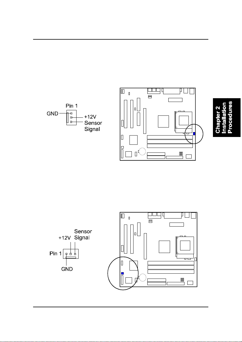
CPU Fan Connector: J2
This connector is linked to the CPU fan. When the system is in S3 suspend
mode, the CPU fan will turn off; when it reverts back to full–on mode, the fan
will turn back on. Please refer to the CPU fan installation manual for more
information.
System Case Fan Connector: J6
The 3-pin connector allows you to link with the cooling fan on the system case
to lower the system temperature.
2 - 15
Page 58
FR31 Mainboard Manual
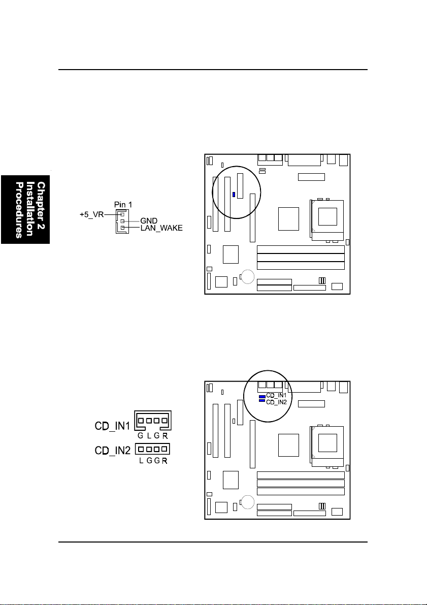
Wake-On-Lan Connector: WOL
This 3-pin connector allows the remote servers to manage the system that
installed this mainboard via your network adapter which also supports WOL.
When you install such a LAN card, please read its installation guide for more
information.
CD Audio-In Connectors: CD_IN1, CD_IN2
The CD_IN1/2 connectors are used for different types for CD drive audio in
port.
2 - 16
Page 59
Installation Procedures
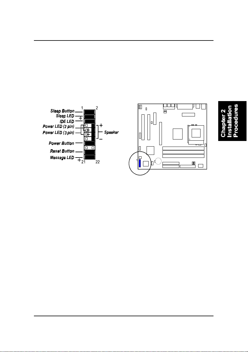
Front Panel Block Connector: FPNL
This block connector includes the connectors for linking with IDE LED, power
LED, sleep LED, power button, message LED, sleep button, reset button and
speaker on the front panel of the system case. Please identify polarities of plug
wires for the case speaker and LEDs. Please ask vendor about this information
when you buy them and install the system by yourself. The plug wires polarities of these buttons will not affect the function.
Message LED is connected with the message LED. When the system is running normally, the indicator is of f. It is controlled by the operating system or
application software.
Reset Button is connected to the reset button. Push this switch to reboot the
system instead of turning the power button off and on.
Power Button is connected with power button. Push this switch allows the
system to be turned on and off rather than using the power supply button.
Power LED is connected with the system power indicator to indicate whether
the system is on/off. It will blink when the system enters suspend mode.
Speaker is connected with the case speaker.
IDE LED is connected to the IDE device indicator. This LED will blink when
the hard disk drives are activated.
Sleep LED is connected with sleep mode indicator.
Sleep Button is connected with sleep button. T o enter the system into power
saving mode, simply press this button when the system is in full-on mode.
2 - 17
Page 60
FR31 Mainboard Manual
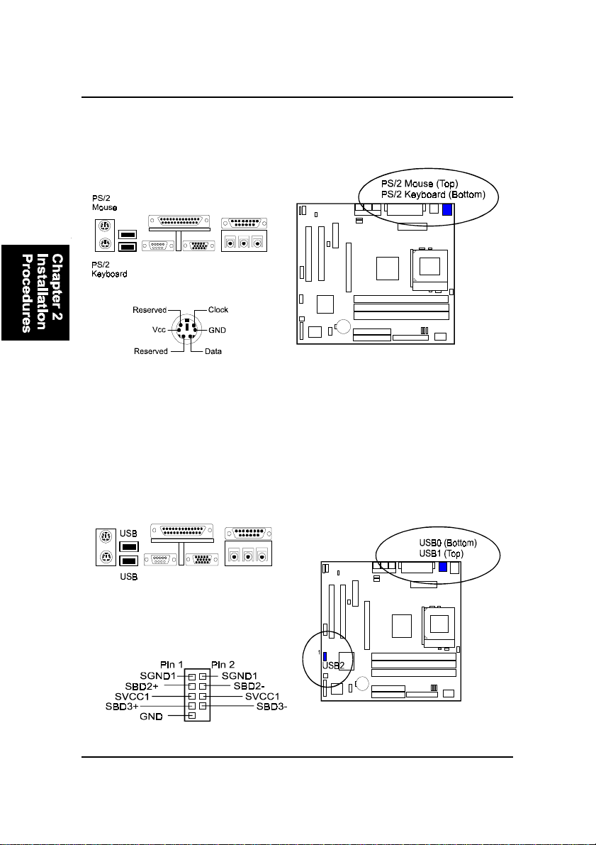
PS/2 Keyboard and Mouse Connector: KB, MS
These two 6-pin female (PS/2 keyboard is purple color and PS/2 mouse is
green color) connectors are used for your PS/2 keyboard and PS/2 mouse.
Universal Serial Bus Connectors: Rear USBs, Front USBs
These two black connectors integrated on the edge of the board are used for
linking with USB peripheral devices. This board also provides a connector
USB2 for linking with the two USB sockets on the front panel of some system
cases. Please note your operating system must support USB features, such as
MS Windows 98, MS W indows 95 OSR2.5 with USB Supplement.
The figure below is the pin assignment
of the USB2 connector for two front panel
USB connections.
2 - 18
Page 61
Installation Procedures
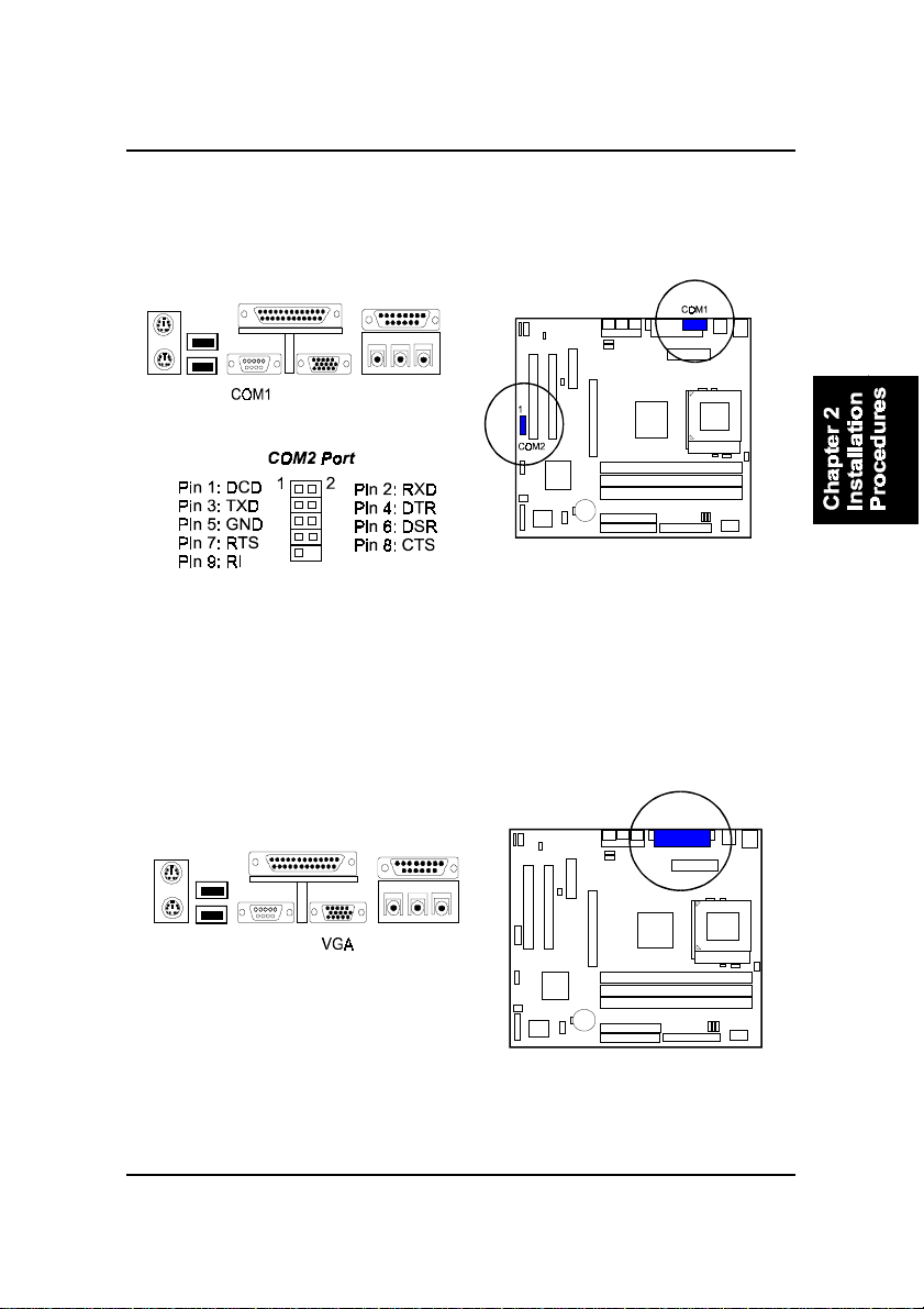
Serial Port Connectors: COM1, COM2
COM1 (9-pin D-sub male connector with teal color) and COM2 (9-pin male
connector) allow you to connect with your devices that use serial ports, such
as a serial mouse or an external modem.
Video Graphics Accelerator Connector: VGA
This 15-pin female D-sub blue connector is connected to your display monitor.
2 - 19
Page 62
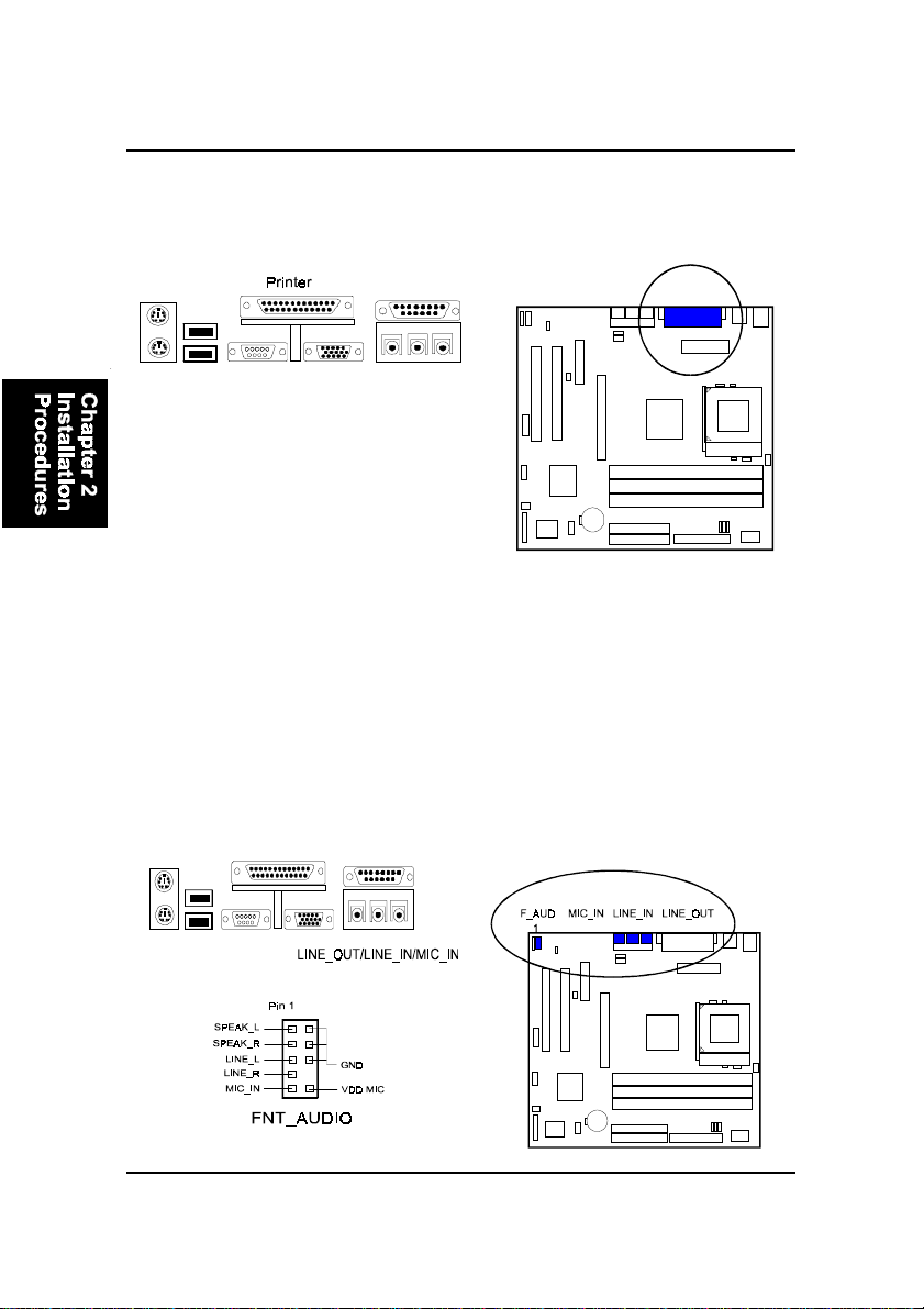
FR31 Mainboard Manual
Printer Connector: LPT
This 25-pin D-Sub female burgundy-colored connector is attached to your
printer.
Audio I/O Jacks: LINE_OUT, LINE_IN, MIC_IN,
FNT_AUDIO
LINE_OUT (lime) can be connected to headphones or preferably powered
speakers. LINE_IN (light blue) allows tape players or other audio sources to
be recorded by your computer or played through the LINE_OUT. MIC_IN
(pink) allows microphones to be connected for voice input. The mainboard
also provides you with a front panel audio port connector, FNT_AUDIO,
when needed. Its pin definitions were presented below .
2 - 20
Page 63
Installation Procedures
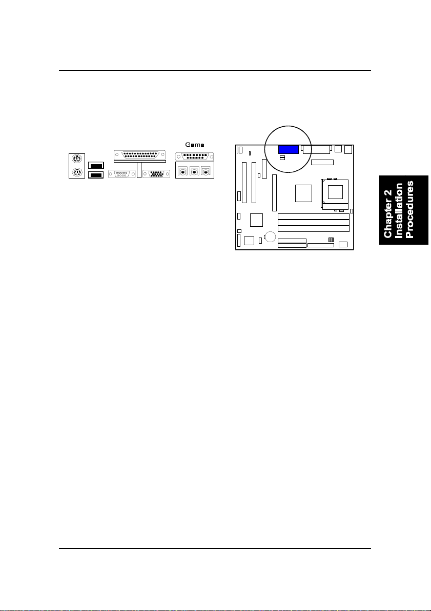
Game/MIDI Connector: GAME
This 15-pin female gold-colored connector allows you to connect game joysticks or game pads. Connect MIDI devices for playing or editing audio.
2 - 21
Page 64

FR31 Mainboard Manual
This Page Left Blank for Note
2 - 22
Page 65
BIOS Setup
Chapter 3
BIOS Setup
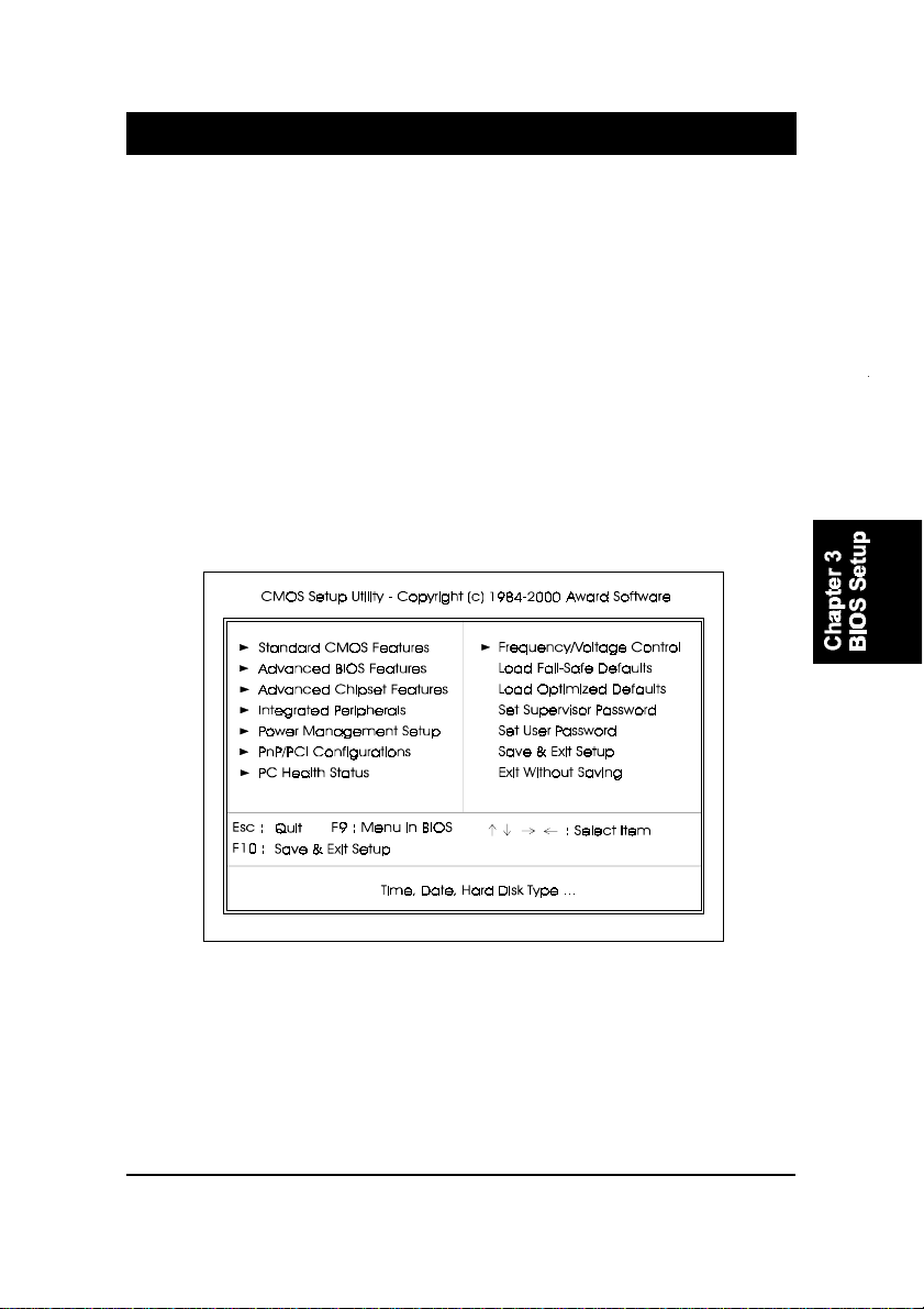
The mainboard comes with the chip that A ward BIOS that contains the ROM
Setup information of your system. (This chip serves as an interface between
the processor and the rest of the mainboard’s components.) This section
explains the information contained in the Setup program and tells you how to
modify the settings according to your system configuration.
CMOS Setup Utility
A Setup program, built into the system BIOS, is stored in the CMOS. This
Setup utility program allows updates to the mainboard configuration settings.
It is executed when the user changes system configuration; user changes
system backup battery; or the system detects a configuration error and asks
the user to run the Setup program. Use the arrow keys to select and press
Enter to run the selected program.
3 - 1
Page 66
FR31 Mainboard Manual
Standard CMOS Setup
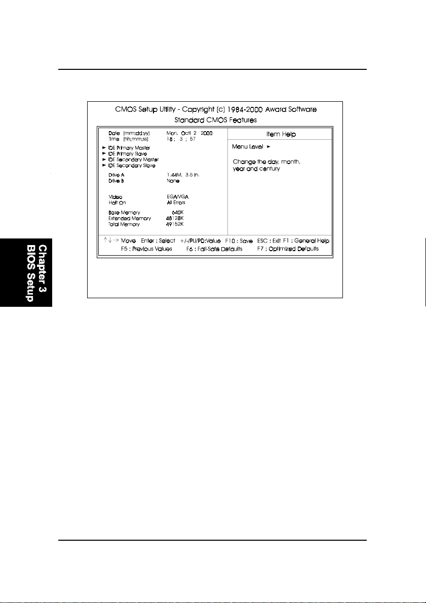
The Standard CMOS Setup screen is displayed above. Each item may have
one or more option settings. The system BIOS automatically detects memory
size, thus no changes are necessary. Use the arrow keys to highlight the item
and then use PgUp or PgDn keys to select the value you want in each item.
Hard Disk Configurations
Capacity: The hard disk size. The unit is Bytes.
Cylinder: The cylinder number of the hard disk.
Head: The read/write head number of hard disk.
Precomp: The cylinder number at which the disk drive changes the write
current.
Landing Zone: The cylinder number that the disk drive heads (read/write)
are seated when the disk drive is parked.
Sector: The sector number of each track defined on the hard disk.
3 - 2
Page 67
Advanced BIOS Features
BIOS Setup
3 - 3
Page 68

FR31 Mainboard Manual
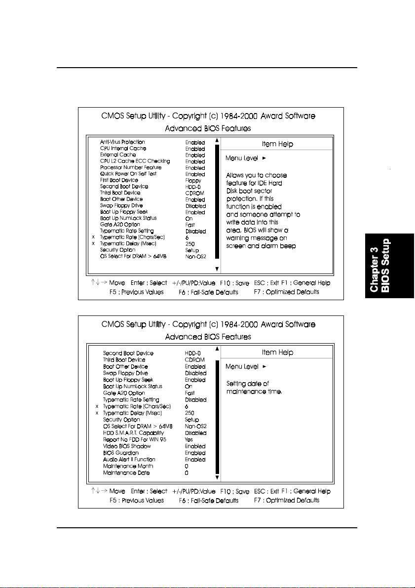
Anti-Virus Protection
This feature starts the virus scan tool to detect if boot virus in boot sector
of the first hard disk drive when booting up.
The options are: Enabled, Disabled.
CPU Internal Cache
When enabled, improves the system performance. Disable this item when
testing or trouble-shooting. The options are: Enabled, Disabled.
External Cache
When enabled, supports an optional cache SRAM. This feature allows
you to disable the cache function when the system performance is unstable to run some software. The options are: Enabled, Disabled.
Processor Number Feature
If a Pentium III processor is installed on this mainboard, the system BIOS
will allow other utilities to access the Intel Pentium III serial number while
this feature set at Enabled. The options are: Enabled, Disabled.
Quick Power On Self T est
When enabled, allows the BIOS to bypass the extensive memory test.
The options are: Enabled, Disabled.
First Boot Device
This feature allows user to select the boot device priority . The options are:
Floppy , LS120, HDD-0, SCSI, CDROM, HDD-1, HDD-2, HDD-3, ZIP100,
USB-FDD, USB-ZIP , USB-CDROM, USB-HDD, LAN, Disabled.
Second Boot Device
This feature allows user to select the boot device priority . The options are:
Floppy , LS120, HDD-0, SCSI, CDROM, HDD-1, HDD-2, HDD-3, ZIP100,
USB-FDD, USB-ZIP , USB-CDROM, USB-HDD, LAN, Disabled.
Third Boot Device
This feature allows user to select the boot device priority . The options are:
Floppy , LS120, HDD-0, SCSI, CDROM, HDD-1, HDD-2, HDD-3, ZIP100,
USB-FDD, USB-ZIP , USB-CDROM, USB-HDD, LAN, Disabled.
3 - 4
Page 69

BIOS Setup
Boot Other Device
This feature allows user to select the boot device priority .
The options are: Enabled, Disabled.
Swap Floppy Drive
Allows you to switch the order in which the operating system accesses
the floppy drives during boot up.
The options are: Enabled, Disabled.
Boot Up Floppy Seek
When enabled, assigns the BIOS to perform floppy diskette drive tests by
issuing the time-consuming seek commands.
The options are: Enabled, Disabled.
Boot Up Numlock Status
When set to On, allows the BIOS to automatically enable the Num Lock
Function when the system boots up. The options are: On, Off.
Gate A20 Option
When set at Fast, allows a faster access response under Protected mode.
The options are: Fast, Normal.
Typematic Rate Setting
The term typematic means that when a keyboard key is held down, the
character is repeatedly entered until the key is released.
The options are: Disabled, Enabled.
Typematic Rate (Chars/Sec)
This feature is available only if the above item, T ypematic Rate Setting, is
set at Enabled. Sets the rate of a character repeat when the key is held
down. The options are: 6, 8, 10, 12, 15, 20, 24, 30.
Typematic Delay (Msec)
This feature is available only if the item, Typematic Rate Setting, is set at
Enabled. Sets the delay time before a character is repeated.
The options are: 250, 500, 750, 1000 millisecond.
3 - 5
Page 70
FR31 Mainboard Manual
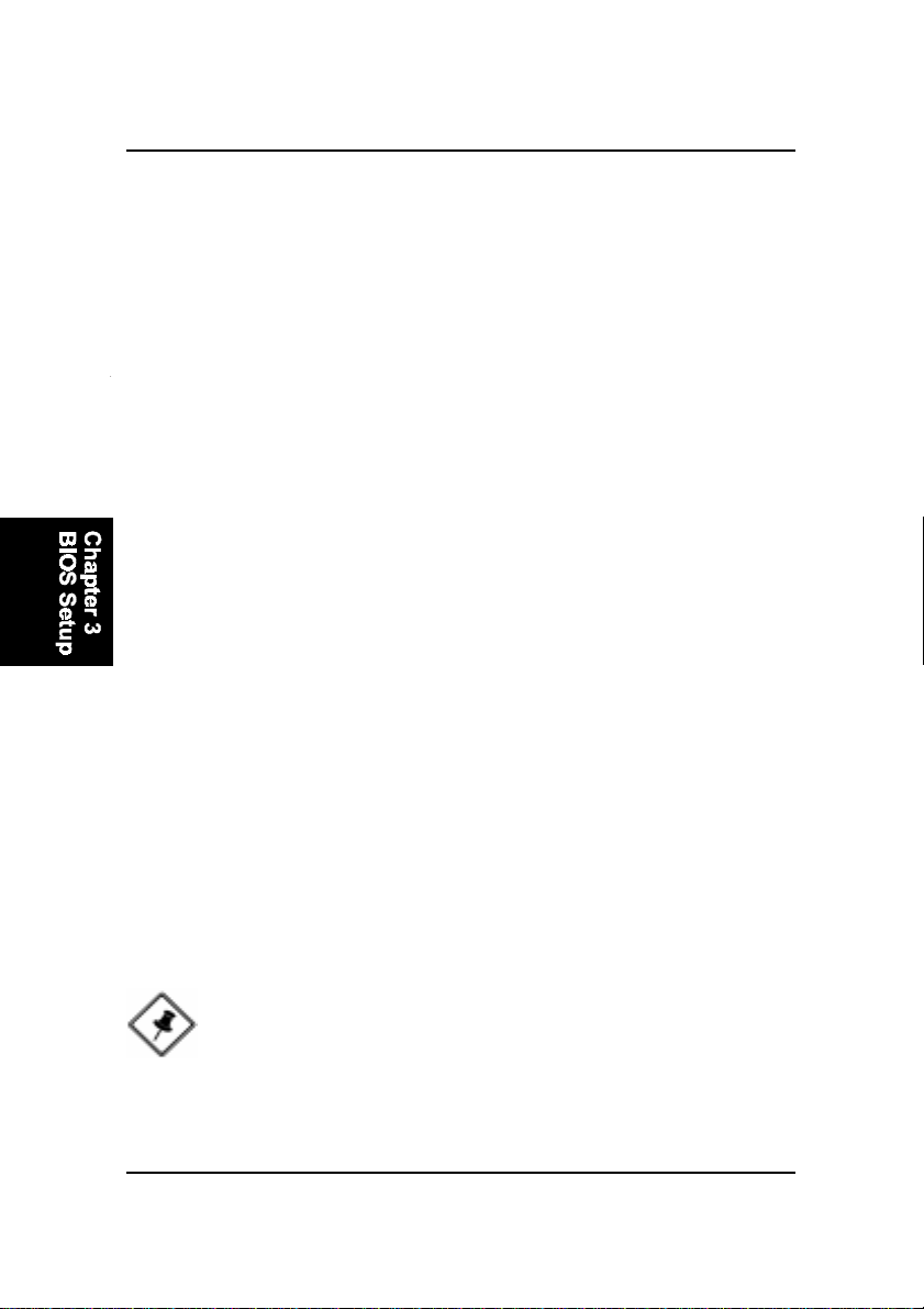
Security Option
Allows you to set the security level of the system.
The options are: Setup, System.
OS Select For DRAM > 64MB
If your operating system (OS) is OS/2, select the option OS2. Otherwise,
stay with the default setting Non-OS2.
The options are: Non-OS2, OS2.
HDD S.M.A.R.T . Capability
S.M.A.R.T . stands for Self-Monitoring and Analysis Reporting Technology which allows your hard disk drive to report any read/write errors and
issues a warning with LDCM installed.
The options are: Disabled, Enabled.
Report No FDD For WIN 95
When the field under the Standard CMOS Setup Menu for Drive A and/or
Drive B is set at None, users must set this field is set at Y es for it to function
properly. Otherwise, set at No, even if field for Drive A and/or Drive B is set
at None, system will still detect and recognize of a floppy drive(s).
The options are: Yes, No.
Video BIOS Shadow
Allows the BIOS to copy the video ROM code of the add-on video card to
the system memory for faster access.
The options are: Enabled, Disabled.
BIOS Guardian
It allows the system to prevent computer viruses. Users will need to disable it to update BIOS. The options are: Enabled, Disabled.
NOTE: Please disable this BIOS feature about BIOS Guardian
before you start to reflash BIOS.
3 - 6
Page 71

BIOS Setup
Audio Alert II Function
It allows you to disable the FIC Audio Alert II function. If you have Audio
Alert II onboard, its function works normally when set at Enabled.
The options are: Enabled, Disabled.
Maintenance Month
It allows you to set the month of maintenance time.
The options are: 0, January, Febuary, ... , December.
Maintenance Date
It allows you to set the date of maintenance time.
The options are: 0, 1, ..., 31.
3 - 7
Page 72
FR31 Mainboard Manual
Advanced Chipset Features
3 - 8
Page 73

BIOS Setup
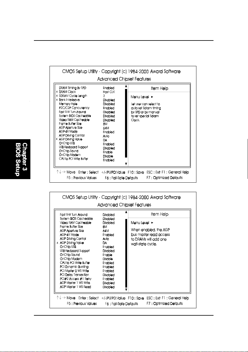
DRAM Timing By SPD
This item allows you to use supports of Serial Presence Detect (SPD), the
system BIOS can recongnize its specificity, then do automatic timer setting
SPD data. If you set any timing manually, please set this feature at Disabled. The options are: Enabled, Disabled.
DRAM Clock
The feature allows users to select the DRAM clock.
The options are: Host CLK, HCLK+33M, HCLK-33M.
SDRAM Cycle Length
This item will function only when SDRAM DIMM/s are installed on the
mainboard (BIOS auto detection). If the CAS latency of your SDRAM
DIMM is 2, set it at 2 to enhance your system performance. If the CAS
latency of your SDRAM DIMM is 3, stay with the default setting, 3.
The options are: 3, 2.
Bank Interleave
This item allows users to select the bank interleave function of DRAM,
when the feature DRAM Timing By SPD set at Disabled.
The options are: Disabled, 2 Bank, 4 Bank.
Memory Hole
When you install a Legacy ISA card, this feature allows you to select the
memory hole’s address range of the ISA cycle when the processor accesses the selected address area. Please read your card manual for detail
information. When disabled, the memory hole at the 14MB (or 15MB)
address will be treated as a DRAM cycle when the processor accesses the
15~16MB address area.
The options are: 15M - 16M, Disabled.
P2C/C2P Concurrency
This feature allows users to set PCI/AGP Master-to-CPU/ CPU-to-PCI/
AGP Slave concurrent.
The options are: Enabled, Disabled.
Fast R-W Turn Around
It allows users to set DRAM fast read-to-write turn around.
The options are: Enabled, Disabled.
3 - 9
Page 74

FR31 Mainboard Manual
System BIOS Cacheable
When enabled, allows the ROM area F000H-FFFFH to be cacheable when
cache controller is activated. The options are: Enabled, Disabled.
Video RAM Cacheable
When set at Enabled, allows the system to use the video RAM from cache
RAM, instead of the slower DRAMs or ROMs.
The options are Enabled, Disabled.
Frame Buffer Size
It allows user to select the frame buffer size of VGA share memory .
The options are 2M, 4M, 8M, 16M, 32M.
AGP Aperture Size
It allows you to select the main memory frame size for AGP use.
The options are 4M, 8M, 16M, 32M, 64M, 128M.
AGP-4X Mode
This feature allows user to select the AGP mode be to 2x or 4x when an
AGP add-in card installed. However, when set at Enabled and the AGP
card only support 1x mode, the system will fall back 1x mode automatically .
The options are: Enabled, Disabled.
AGP Driving Control / AGP Driving V alue
These two features allow user to improve the performance of AGP card
manually by pressing Page Down/Page UP key if necessary .
The options of AGP Driving Control are: Auto, Manual.
OnChip USB
When enabled, this feature allows you to use the onboard USB feature.
The options are: Enabled, Disabled.
USB Keyboard Support
This feature will appear only if the above item Onchip USB is set at Enabled. Set this feature to Enabled to use a USB keyboard with your system.
The options are: Disabled, Enabled.
3 - 10
Page 75

BIOS Setup
OnChip Sound
This feature allows you to disable the onboard audio function if needed.
The options are: Enable, Disable.
OnChip Modem
This feature allows you to disable the embeded modem function if needed.
The options are: Enable, Disable.
CPU to PCI Write Buffer
When enabled, allows data and address access to the internal buffer of
the system controller; so the processor can be released from the waiting
state. The options are: Enabled, Disabled.
PCI Dynamic Bursting
When enabled, the PCI controller allows Bursting PCI transfer if the consecutive PCI cycles come with the address falling in same 1KB space. This
improves the PCI bus throughput.
The options are: Enabled, Disabled.
PCI Master 0 WS Write
When enabled, allows a zero-wait-state-cycle delay when the PCI master
drive writes data to DRAM. The options are: Enabled, Disabled.
PCI Delay Transaction
Enable this feature to abort the current CPI master cycle and to accept the
new PCI master request, it reaccepts the original PCI master and returns
the PCI data phase to the original PCI master.
The options are: Disabled, Enabled.
PCI#2 Access #1 Retry
When enabled, the AGP (PCI#2) access to PCI (PCI#1) will be retried until
the maximum count. The options are: Disabled, Enabled.
3 - 11
Page 76
FR31 Mainboard Manual
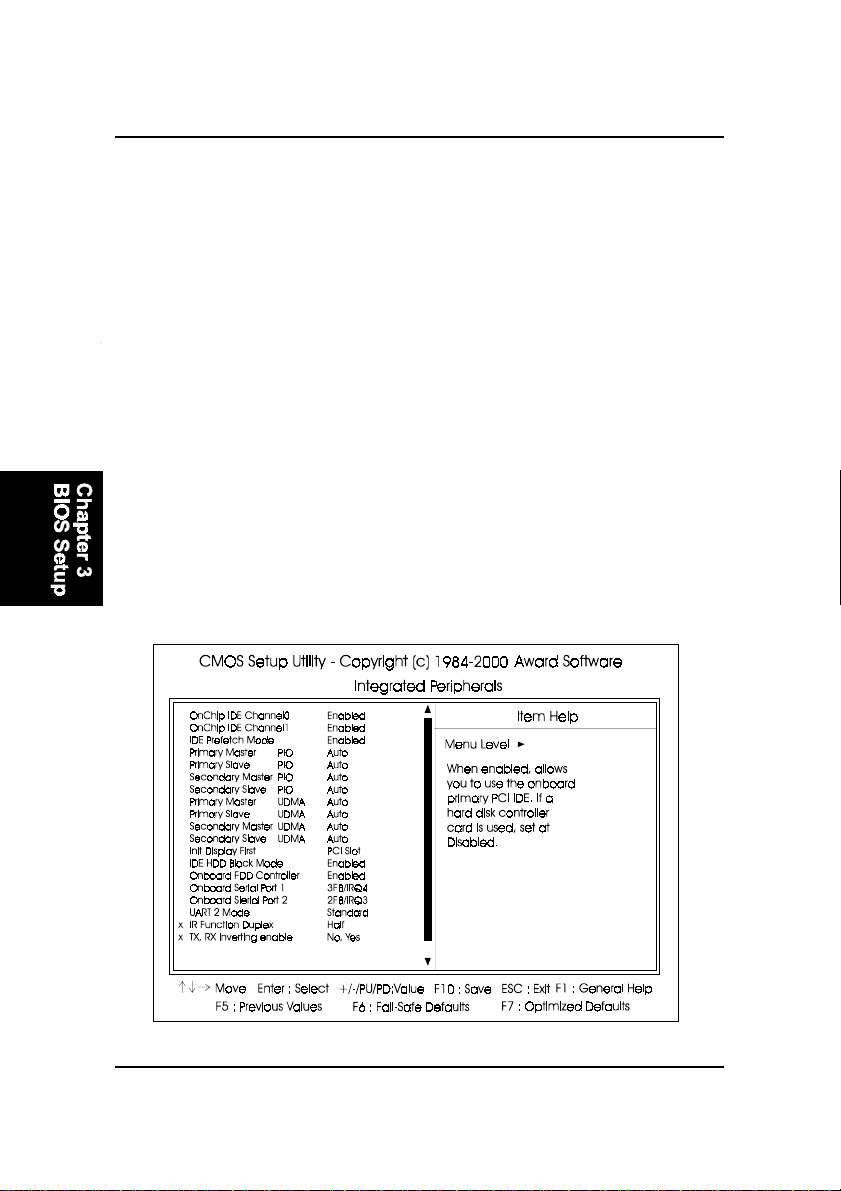
AGP Master 1 WS Write
When enabled, the AGP bus master write access to DRAMs will add one
wait-state cycle. The options are: Disabled, Enabled.
AGP Master 1 WS Read
When enabled, the AGP bus master read access to the DRAMs will add
one wait-state cycle. The options are: Disabled, Enabled.
Integrated Peripherals
3 - 12
Page 77
BIOS Setup
OnChip IDE Channel0
When enabled, allows you to use the onboard primary PCI IDE. If a hard
disk controller card is used, set at Disabled.
The options are: Enabled, Disabled.
OnChip IDE Channel1
When enabled, allows you to use the onboard secondary PCI IDE. If a
hard disk controller card is used, set at Disabled.
The options are: Enabled Disabled.
IDE Prefetch Mode
When set at Enabled, it allows data to be posted to and prefetched from
the primary IDE data ports. Data prefetching is initiated when a data port
read occurs. The read prefetch eliments latency to the IDE data ports and
allows them to be performed back to back for the highest possible PIO data
transfer rates. The first data port read of a sector is called the demand read.
Subsequent data port reads from the sector are called prefetch reads. The
demand read and all prefetch reads must be of the same size (16 or 32 bits).
The options are: Enabled, Disabled.
3 - 13
Page 78

FR31 Mainboard Manual
Primary Master PIO
Allows an automatic or a manual configuration of the PCI primary IDE hard
disk (master) mode. The options are: Auto, Mode 0, Mode 1, Mode 2,
Mode 3, Mode 4.
Primary Slave PIO
Allows an automatic or a manual configuration of the PCI primary IDE hard
disk (slave) mode. The options are: Auto, Mode 0, Mode 1, Mode 2, Mode
3, Mode 4.
Secondary Master PIO
Allows an automatic or a manual configuration of the PCI secondary IDE
hard disk (master) mode. The options are: Auto, Mode 0, Mode 1, Mode 2,
Mode 3, Mode 4.
Secondary Slave PIO
Allows an automatic or a manual configuration of the PCI secondary IDE
hard disk (slave) mode. The options are: Auto, Mode 0, Mode 1, Mode 2,
Mode 3, Mode 4.
Primary Master UDMA
Allows you to select the first PCI IDE channel of the first master hard disk
mode or to detect it by the BIOS if the hard disk supports UDMA (Ultra
DMA, faster than DMA). The options are: Auto, Disable.
IDE Primary Slave UDMA
Allows you to select the first PCI IDE channel of the first slave hard disk
mode or to detect it by the BIOS if the hard disk supports UDMA (Ultra
DMA, faster than DMA). The options are: Auto, Disable.
IDE Secondary Master UDMA
Allows you to select the second PCI IDE channel of the secondary master
hard disk mode or to detect it by the BIOS if the hard disk supports UDMA
(Ultra DMA, faster than DMA). The options are: Auto, Disable.
IDE Secondary Slave UDMA
Allows you to select the second PCI IDE channel of the secondary slave
hard disk mode or to detect it by the BIOS if the hard disk supports UDMA
(Ultra DMA, faster than DMA). The options are: Auto, Disable.
3 - 14
Page 79

BIOS Setup
Init Display First
When you install an AGP VGA card and a PCI VGA card on the board, this
feature allows you to select the first initiation of the monitor display from
which card. The options are: PCI Slot, AGP .
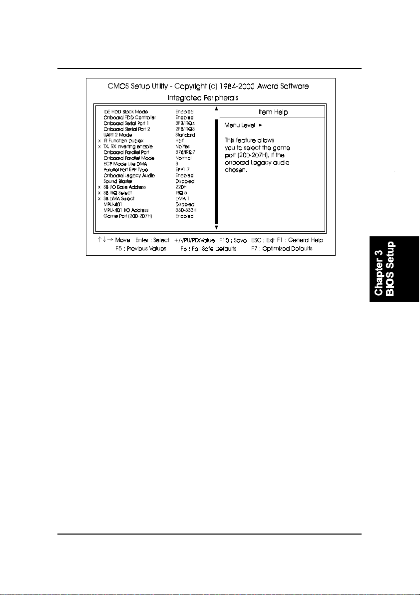
IDE HDD Block Mode
When enabled, the system executes read/write requests to hard disk in
block mode. The options are: Enabled, Disabled.
Onboard FDD Controller
When enabled, the floppy diskette drive (FDD) controller is activated.
The options are: Enabled, Disabled.
Onboard Serial Port 1 / Onboard Serial Port 2
If the serial port 1/2 uses the onboard I/O controller, you can modify your
serial port parameters. If an I/O card needs to be installed, COM3 and
COM4 may be needed. The options are: Disabled, 3F8/IRQ4, 2F8/IRQ3,
3E8/IRQ4, 2E8/IRQ3, Auto.
UART 2 Mode
Select an operating mode for the second serial port. Set at
Standard, if you use COM2 as the serial port as the serial port,
instead as an IR port. The options are: Standard, ASK-IR, HPSIR.
IR Function Duplex
This feature is available only it the above item , UART2 Mode, is set at
ASKIR or HPSIR. It allows you to select the infrared data transaction way.
The options are: Half , Full.
TX, RX Inverting Enable
This feature is available only it the above item , UART2 Mode, is set at
ASKIR or HPSIR. It allows you to select the active signals of the reception end and the transmission end.
The options are: No, Y es; Yes, Y es; No, No; Yes, No.
3 - 15
Page 80

FR31 Mainboard Manual
Onboard Parallel Port
Allows you to select from a given set of parameters if the parallel port uses
the onboard I/O controller.
The options are: 378/IRQ7, 278/IRQ5, 3BC/IRQ7, Disabled.
Onboard Parallel Port Mode
Allows you to connect with an advanced printer.
The options are: Normal, EPP , ECP, ECP/ ECP .
ECP Mode Use DMA
This feature allows you to select Direct Memory Access (DMA) channel if
the ECP mode selected. The options are: 3, 1.
Parallel Port EPP Type
This feature allows you to select the EPP type for the parallel port.
The options are: EPP1.9, EPP1.7.
Onboard Legacy Audio
Allow use the audio function under DOS mode.
The options are: Enabled, Disabled.
Sound Blaster
This feature allows you to select the Sound Blaster, if the onboard Legacy
audio chosen. The options are: Enabled, Disabled.
SB I/O Base Address
This feature allows you to select the SB I/O base address, if the onboard
Legacy audio chosen. The options are: 220H, 240H, 260H, 280H.
SB IRQ Select
This feature allows you to select the SB IRQ, if the onboard Legacy audio
chosen. The options are: IRQ 5, IRQ 7, IRQ 9, IRQ 10.
SB DMA Select
This feature allows you to select the SB DMA channel, if the onboard
Legacy audio chosen.
The options are: DMA 1, DMA 2, DMA 3, DMA0.
3 - 16
Page 81
BIOS Setup
MPU-401
This feature allows you to select MPU-401, if the onboard Legacy audio
chosen. The options are: Disabled, Enabled.
MPU-401 I/O Address
This feature allows you to select the MPU-401 I/O address, if the onboard
Legacy audio chosen.
The options are: 300-303H, 310-313H, 320-323H, 330-333H.
Game Port (200-207H)
This feature allows you to select the game port (200-207H), if the onboard
Legacy audio chosen.
The options are: Enabled, Disabled.
Power Management Setup
3 - 17
Page 82

FR31 Mainboard Manual
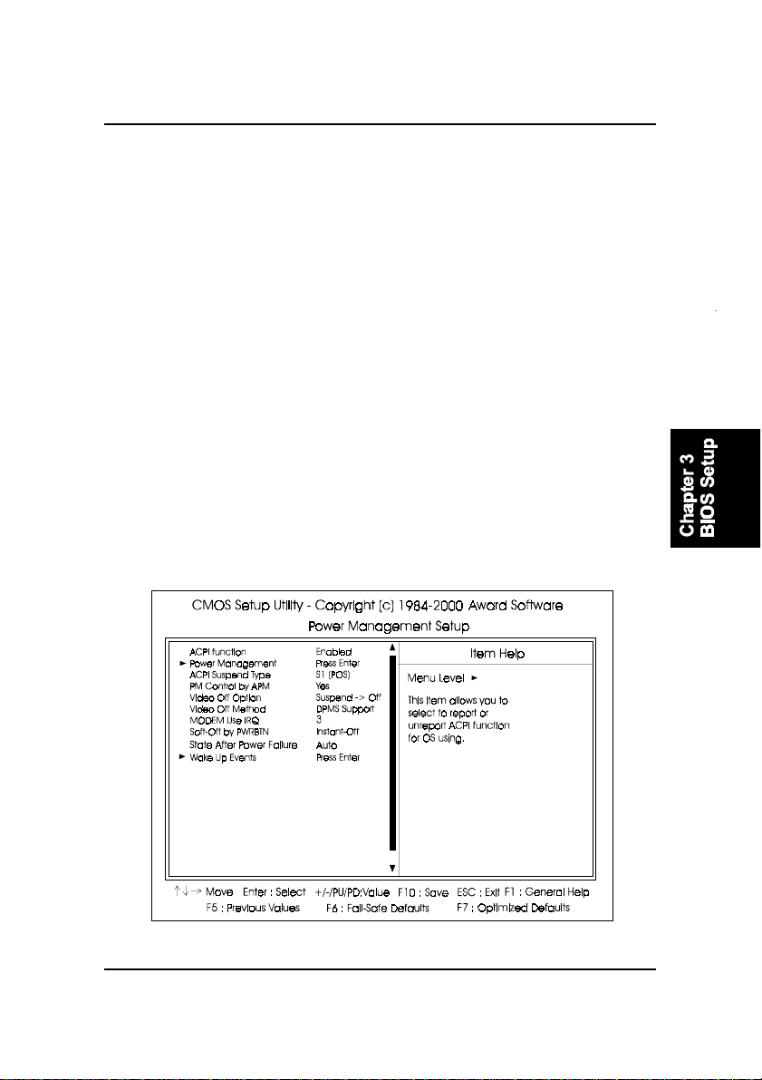
ACPI function
This item allows user to select to report or not report ACPI function for
operating system use. The options are: Enabled, Disabled.
Power Management
This item allows you to adjust the power management features.
Select User Define for configuring your own power management features.
Min Saving initiates all predefined timers in their minimum values. Max
Saving, on the other hand, initiates maximum values. The options are: User
Define, Min Saving, Max Saving.
HDD Power Down
The option lets the BIOS turn the HDD motor off when system is in Suspend mode. Selecting 1 Min..15 Min allows you define the HDD idle time
before the HDD enters the Power Saving Mode.
The options 1 Min..15 Min will not work concurrently . When HDD is in the
Power Saving Mode, any access to the HDD will wake the HDD up.
The options are: Disable, 1 Min..15 Min.
Doze Mode
When disabled, the system will not enter Doze mode. The specified time
option defines the idle time the system takes before it enters Doze mode.
The options are: Disable, 1, 2, 4, 6, 8, 10, 20, 30, 40 Min, 1 Hour.
Suspend Mode
When disabled, the system will not enter Suspend mode. The specified
time option defines the idle time the system takes before it enters Suspend
mode. The options are: Disable, 1, 2, 4, 6, 8, 10, 20, 30, 40 Min, 1 Hour.
ACPI Suspend Type
This item allows you to select ACPI suspend types.
The options are: S1(POS), S3 (STR).
3 - 18
Page 83

BIOS Setup
PM Control by APM
The option No allows the APM (Advanced Power Management) specification be ignored. Selecting Y es will allow the BIOS wait for APM’s prompt
before it enters Doze mode, Standby mode, or Suspend mode. If the APM
is installed, it will prompt the BIOS to set the system into power saving
mode when all tasks are done. The options are: No, Yes.
Video Off Option
This feature provides the selections of the video display power saving
mode. The option Suspend - Off allows the video display to go blank if the
system enters Suspend mode. The option All Modes - Off allows the video
display to go blank if the system enters Doze mode or Suspend mode. The
option Always On allows the video display to stay in Standby mode even
when the system enters Doze or Suspend mode.
The options are: Suspend - Off, All Modes -> Off, Always On.
Video Off Method
The option V/H SYNC+Blank allows the BIOS to blank off screen display
by turning off the V-Sync and H-Sync signals sent from add-on VGA card.
DPMS Support allows the BIOS to blank off screen display by your addon VGA card which supports DPMS (Display Power Management Signaling function). Blank Screen allows the BIOS to blank off screen display by
turning off the red-green-blue signals.
The options are: V/H SYNC+Blank, DPMS Support, Blank Screen.
MODEM Use IRQ
This feature allows you to select the IRQ# to meet your modem’s IRQ#.
The options are: NA, 3, 4, 5, 7, 9, 10, 11.
Soft-Off by PWR-BTTN
The selection Delay 4 Sec. will allow the system shut down after 4 seconds
after the power button is pressed. The selection Instant-Off will allow the
system shut down immediately once the power button is pressed.
The settings are: Delay 4 Sec, Instant-Off.
3 - 19
Page 84

FR31 Mainboard Manual
State After Power Failure
The item allows you to select the state that your personal computer returns to after a power failure. If set at Off, the system will not boot after a
power failure. If set On, the system will restart after power failure.
The settings are: Auto, On, Off.
VGA
When set at On, any VGA activity will awake the system.
The options are: OFF , ON.
LPT & COM
When LPT/COM is selected, any access of LPT and COM ports will awake
the system. Likewise, either LPT or COM is chosen, the system will be
awaken by any activity of LPT or COM port.
The options are: LPT/COM, LPT , COM, NONE.
HDD & FDD
When it is set at ON, any access happened at hard drives and floppy
drives will awake the system.
The options are: OFF , ON.
PCI Master
To set this feature at ON activates that Power Management feautre (PM)
wake-up event for the PCI bus master card.
The options are: OFF , ON.
PowerOn by PCI Card
When set at Enabled, any PCI-PM event awakes the system from a PCIPM controlled state.
The options are Disabled, Enabled.
Modem Ring Resume
An input signal on the serial Ring Indicator (RI) line (in other words, an
incoming call on the modem) awakens the system from a soft off state.
The options are: Enabled, Disabled.
3 - 20
Page 85

BIOS Setup
RTC Alarm Resume
Enabled allows you to set the time the system will be turned on from the
system power-off status. The options are: Enabled, Disabled.
Date (of Month)
This feature allows you to set the day of the alarm starts when the RTC
Alarm Resume From Soft Off is set to be Enabled. The options are: 0, 1..31.
Resume Time (hh:mm:ss)
If an ATX power supply is installed and when RTC Alarm Resume is Enabled, this feature allows you to set the time of the alarm starts when the
RTC Alarm Resume From Soft Of f is set to be Enabled.
The options are: 7: 0: 0. hh (hour) - 0, 1, 2,.., 23; mm (minute) - 0, 1, 2,..,59;
ss (second) - 0, 1, 2,..,59.
Primary INTR
If set at ON, the Primary interrupt (the Primary option in the feature of IRQ#
Acitivity) will make the power management wake up the system.
The options are: ON, OFF .
IRQs Activity Monitoring
After the time period which you set, the system advances from doze mode
to suspend mode in which the CPU clock stops and the screen display is
off. At this moment, if the IRQ activity occurs, the system goes back to
full-on mode directly.
If the IRQ activity which is defined as Non Primary takes place, the system
remains off until the corresponding IRQ handler finishes.
The options of IRQ 3, 4, 5, 6, 7, 8, 9, 10, 11, 12, 13, 14, 15 are: Enabled,
Disabled.
3 - 21
Page 86
FR31 Mainboard Manual
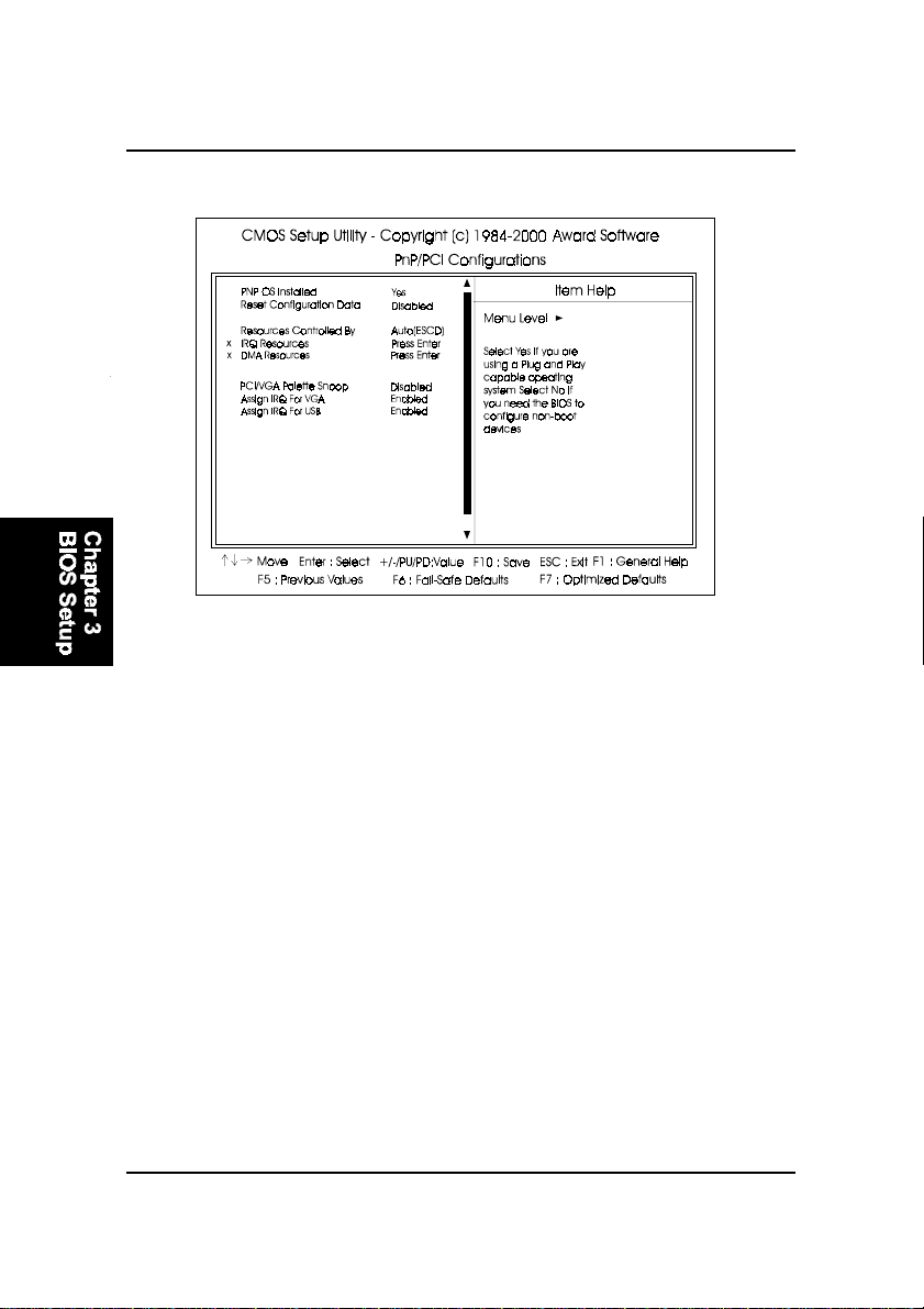
PnP/PCI Configurations
PNP OS Installed
If your operating system is a Plug-and-Play one, such as Windows NT,
Windows 95, select Yes. The options are: No, Yes.
Reset Configuration Data
Enabling it to reset the system Extended System Configuration Data (ESCD)
when you exit Setup if you have installed a new add-on card and the
system reconfiguration has caused such a serious conflict that the operating system can not boot. The options are: Disabled, Enabled.
Resources Controlled By
If set at Auto, the BIOS arranges all system resources. If there exists conflict, select Manual. The options are: Auto (ESCD), Manual.
If the manual options, after the featrue IRQ Resources being pressed, of
IRQ- Assigned T o are: PCI Device, Reserved. When resources were controlled manually, assign each system interrupt a type, depending on each
device type to use the interrupt.
3 - 22
Page 87

BIOS Setup
PCI/VGA Palette Snoop
Set this feature to be enabled if any ISA adapter card installed in the
system requires the VGA palette snoop function.
The options are: Disabled, Enabled.
Assign IRQ For VGA
If your PCI VGA card does not need an IRQ, select Disabled; therefore, an
IRQ can be released for the system use.
The options are: Enabled, Disabled.
Assign IRQ For USB
If you do not use USB devices, select Disabled; therefore, an IRQ can be
released for the system use.
The options are: Enabled, Disabled.
3 - 23
Page 88
FR31 Mainboard Manual
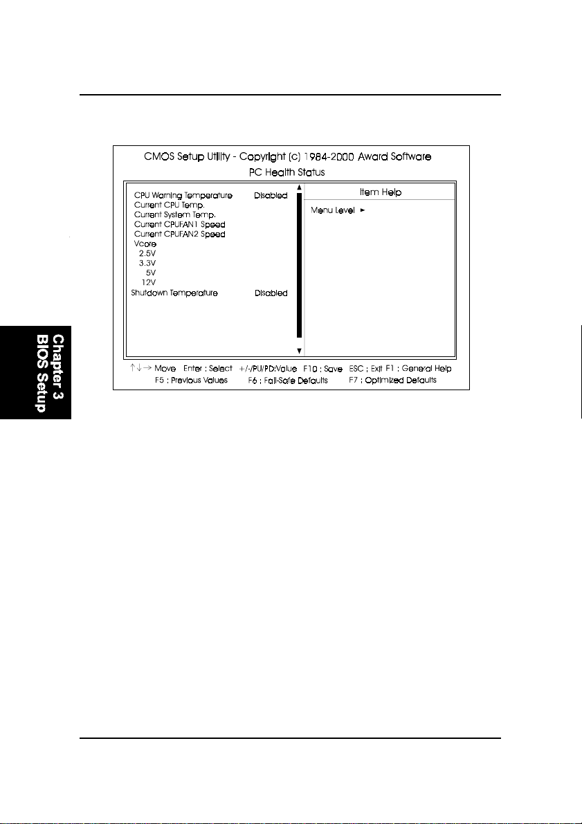
PC Health Status
CPU Warning T emperature
This feature allows you to set the temperature to slow down the CPU clock
frequency. The option list presents all the temperatures that supported by
the board and Disabled.
Current CPU T emp. / Current System T emp. / Current CPUF AN1 Speed
/ Current CPUFAN2 Speed / Vcore / 2.5V / 3.3V / 5V / 12V
These items allow end users and technicians to monitor data provided by
the BIOS on this mainboard. It is not user-configurable.
Shutdown T emperature
This feature helps to shutdown the system when the system temperature
is as high as the selected temperature to prevent from the overheat problem. The option list presents all the temperatures that supported by the
board and Disabled.
3 - 24
Page 89
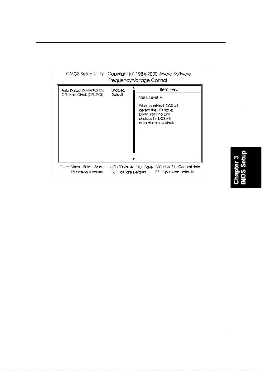
BIOS Setup
Frequency/Voltage Control
Auto Detect DIMM/PCI Clk
When enabled, BIOS will detect the PCI slot and DIMM slot. If no any
device in, BIOS will auto disable its clock.
The options are: Enabled, Disabled.
CPU Host/PCI/Spread Spec.
This feature allows you to select the combinations of CPU/PCI clock frequency and the Spread Spectrum. The default setting, Default, will detect
your CPU/PCI clock frequency/Spread Spectrum automatically . The recommended CPU clock frequencies are 100 and 133MHz. The other options
may effect the system perfomance. If you set a unappropriate option which
leads to a booting problem, keep pressing the Insert key until the display
appears will solve it. The options lists all combinations that provided by
the system BIOS.
3 - 25
Page 90
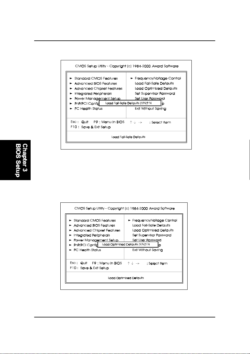
FR31 Mainboard Manual
Load Fail-Safe Defaults
This submenu is selected to diagnose the problem after the computer boots, if
the computer will not boot. These settings do not give optimal performance.
Load Optimized Defaults
This submenu is selected for default settings which provide the best system
performance.
3 - 26
Page 91
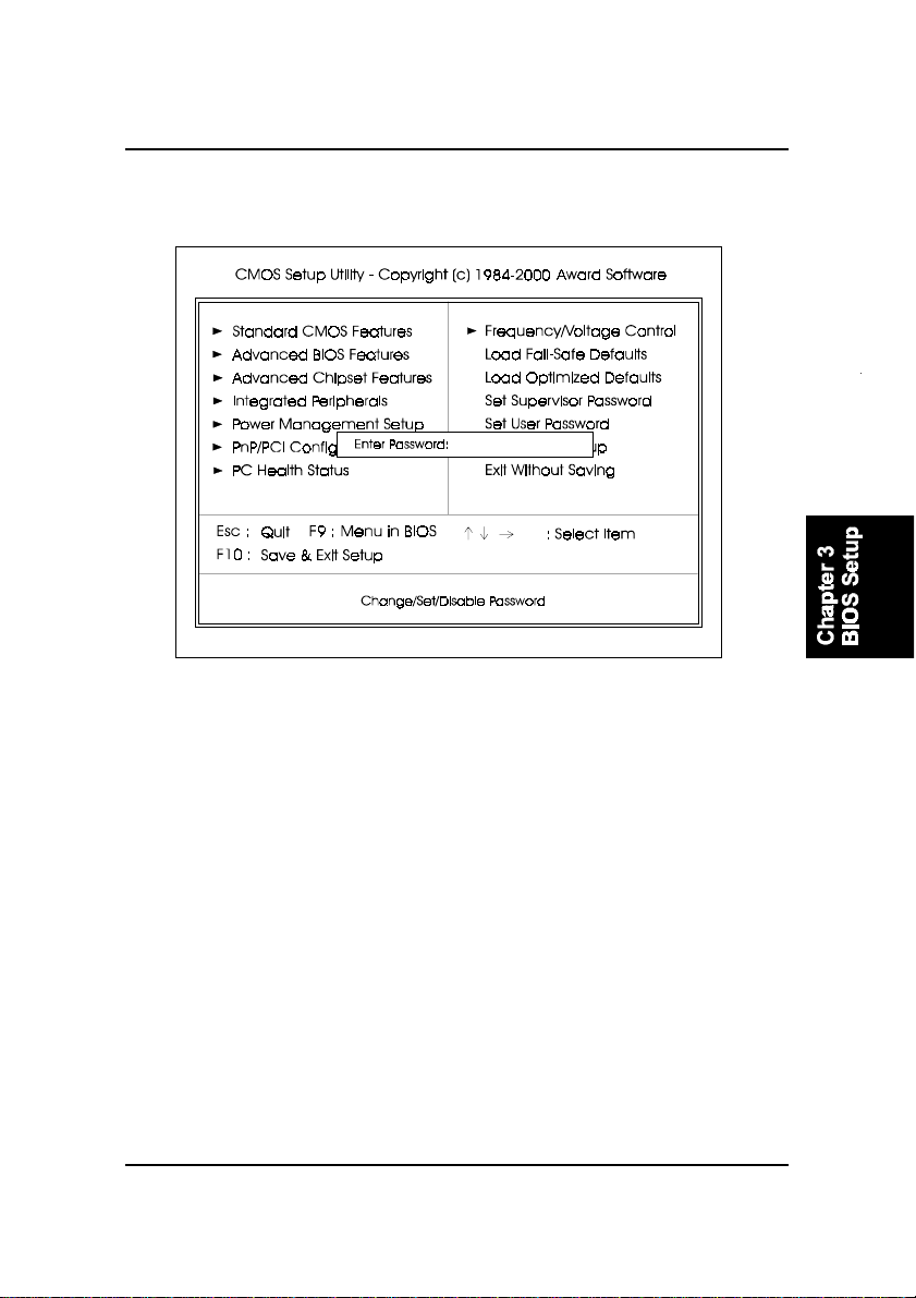
BIOS Setup
Supervisor/User Password
To enable the Supervisor/User passwords, select the item from the Standard
CMOS Setup. Y ou will be prompted to create your own password. Type your
password up to eight characters and press Enter. You will be asked to confirm
the password. Type the password again and press Enter. To disable password,
press Enter twice when you are prompted to enter a password. A message
appears, confirming the password is disabled.
Under the BIOS Feature Setup, if Setup is selected under the Security Option
field and the Supervisor/User Password is enabled, you will be prompted
password every time you try to enter the CMOS Setup Utility. If System is
selected and the Supervisor/User Password is enabled, you will be requested
to enter the Password every time when you reboot the system or enter the
CMOS Setup utility.
3 - 27
Page 92
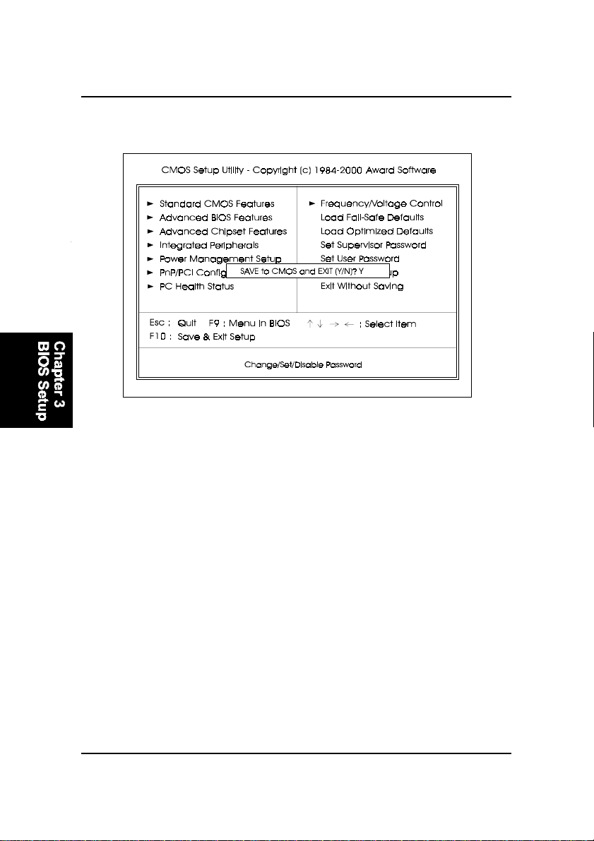
FR31 Mainboard Manual
Save and Exit Setup
After you have made changes under Setup, press Esc to return to the main
menu. Move cursor to Save and Exit Setup or press F10 and then press Y to
change the CMOS Setup. If you did not change anything, press Esc again or
move cursor to Exit Without Saving and press Y to retain the Setup settings.
The following message will appear at the center of the screen to allow you to
save data to CMOS and exit the setup utility: SA VE to CMOS and EXIT (Y/N)?
Exit without Saving
If you select this feature, the following message will appear at the center of the
screen to allow you to exit the setup utility without saving CMOS modifications: Quit Without Saving (Y/N)?
3 - 28
 Loading...