

Page 1

Chapter
4
Hardware Functional Overview
4.1 Overview
The A440 is an IBM PC/AT compatible notebook PC which supports the Socket 370 processor family.
The following are the major features that A440 supports.
Microsoft PC99 and ACPI logo approves.
Offers 1024x768 high resolution LCD display with 12.1“ ,13.3”&14.1’’ panel.
Supports the powerful & flexible Power Management modes.
Support PCI 2.1
Support AGP 2.0
Support ACPI 1.0.
Support SMBios 2.3
Support 66/100 MHz CPU Front Side Bus.
Support a proprietary Port Replicator.
4.2 Summary of H/W Related Spec.
This section describes about the key component list that using on A440 machine and it's related marketing
specification.
FIC A440 Series Service Manual 4-1
Page 2
Hardware Functional Overview
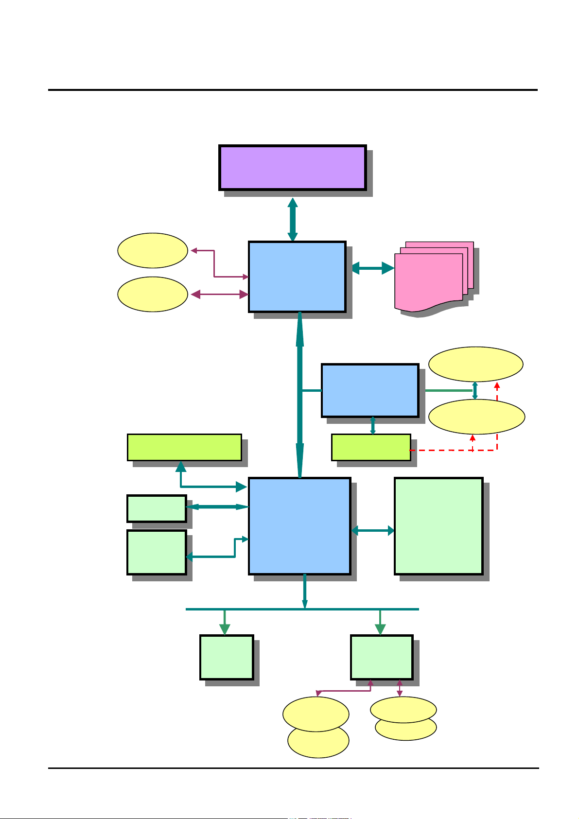
Main components block diagram:
Single Socket 370
CPU
Host Bus
CRT
LCD
AC97 CODEC
USB
HDD
VIA
VT8601
ProMedia
PCMCIA BUS
PCI BUS
VIA
VT82C686A
South Bridge
Ti-1225
CardBus
Card power
SDRAM
SODIMM
SOCKET1
SOCKET0
Super IO
Serial Port
Parallel Port
FDD
CDROM
ISA BUS
ROM
BIOS
GlidePad
S/2
FIC A440 Series Service Manual 4-2
KBC
M38867
EXT KB
INT KB
Page 3
Hardware Functional Overview
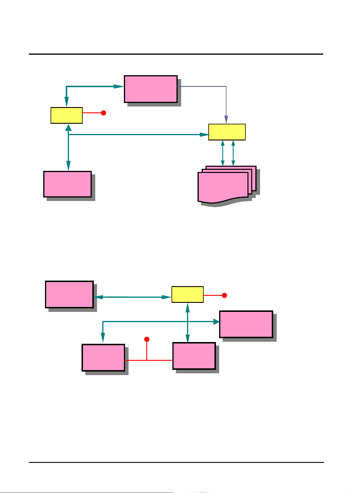
System SMBUS block diagram:
SMBUS
2N7002
VIA
VT82C686
VCC SW
SMBUS
DRAM SMBUS SELECT
SELECT
Clock
Battery SMBUS block diagram:
M38867
SMBUS
SMBUS
VCC Always
SDRAM
SOCKET
VCCSW
2N7002
MAX1617
FIC A440 Series Service Manual 4-3
PIC
Battery
Page 4

Hardware Functional Overview
4.2.1 H/W Key ChipSet List
Controller Chip
Processor Intel Pentium III 650- 850 Mhz Celeron 500 – 667 Mhz
North Bridge VIA ProMedia VT8601
South Bridge VIA ProMedia VT82C686A
VGA Controller Trident Trident 8400 North Bridge Integrated
PCMCIA Controller Ti Ti –1225
Supper I/O Controller VIA South Bridge Integrated
Audio Codec WM WM9701A(AC97 1.03) /WM9703(AC97 2.1)
Audio Amplifier TI TPA0102
Keyboard Controller Mitsubishi M38867
PMU Controller MicroChip PIC-16C62 B ( SSOP )
ROM BIOS Winbond W29C040P
Clock Generator IC Work W156
Temperature Sensor VIA South Bridge embeded
LVDS THC63LVDM63A
MODEM Lucent PCI bus S/W Modem Lucent Mars3
LAN INTEL Intel 82559
Vender Description
FIC A440 Series Service Manual 4-4
Page 5

Hardware Functional Overview
p
4.3 Summary Of BIOS Spec.
Controller Chip
BIOS Feature
CPU
DRAM
Cache
Shadow
Display
Hard Disk
Multi Boot
Plug and Play
Smart Battery
Keyboard Controller
PCMCIA
Port Replicator
Pointing stick
Description
Boot Block / Crisis Rescue
APM 1.2 Compliance
Support PCI 2.1 Spec
Support Win98,Win2000.
Support flash function for new BIOS update
Support 3 Mode FDD
Support DMI 2.0 spec. (SMBIOS 2.3)
Support ACPI 1.0 spec.
Support AGP 2.0.
Support maximal 4 different keyboards on same bios.
Auto detect the CPU type and speed for the Socket 370 or Slot 1based system
Auto sizing and detection. Support PC-100 SDRAM.
Level 2 Sync/Async PBSRAM auto sizing and detection
Always enable CPU L1 and external L2 cache.
Always enable VGA and System BIOS shadow
System auto detects LCD or CRT presence on boot and lid closed.
Support Panning while LCD in a display resolution greater than supported
Support Microsoft Direct 3D
Enhanced IDE spec.
Support auto IDE detection.
Support LBA mode for larger capacity HDD.
Support 32-bit PIO transfer.
Support Multi-sector transfer.
Support Fast PIO mode 1-4 transfer.
Support Ultra DMA 33.
Allow the user to select boot from FDD, HDD, CD-ROM
Support PnP Run Time Service and conflict-free allocation of resource during POST
Support BIOS interface to pass battery information to the application via SMBus.
Support Fn hot keys, two Windows hot keys, built-in Glide Pad and external PS/2
mouse/keyboard
Compliant with PCMCIA 2.1 specification.
I/O port replicator duplicates the following ports
Video port
Printer port
COM1 port
PS/2 Mouse & Standard Keyboard port
USB Port
DC In Jack
The pointing stick device is the small red knob ( it looks lie a pencil eraser ) that sits
just below the [G] and [H] keys of your keyboard. This pressure-sensitive device
translates the pressure of your fingertip on the knob into movement of the cursor. Shift
the
ressure of your fingertip slightly in the direction in which you want to move the
FIC A440 Series Service Manual 4-5
Page 6

Power Management
Support
Hardware Functional Overview
cursor. The two switches below the touchpad serve as the left and right mouse buttons
and can be used with either the pointing stick or the touchpad.
The power management is compliant with APM 1.2 specification and supports the
following power state:
On Mode
Doze Mode (This mode is transparent to user)
Suspend to RAM (STR) Mode
Suspend to Disk (STD) Mode
Off Mode ( Also support Soft-Off Mode, SOff)
FIC A440 Series Service Manual 4-6
Page 7

Hardware Functional Overview
4.4 System
4.4.1 System Memory
The system main memory consists of SDRAM on 64-bit bus. The memory size options range from
32/64/128 MB upward. The BIOS will automatically detect the amount of memory in the system and
configure CMOS accordingly during the POST (Power-On-Self-Test) process. This must be done in a way
that requires no user interaction.
DRAM Combination Configuration
Base SO-DIMM DRAM slot Expansion SO-DIMM DRAM slot Total Size
(Bank 0&1) (Bank 2&3)
32MB NIL 32MB
32MB 32MB 64MB
32MB 64MB 96MB
32MB 128MB 160MB
64MB NIL 64MB
64MB 32MB 96MB
64MB 64MB 128MB
64MB 128MB 192MB
128MB NIL 128MB
128MB 32MB 160MB
128MB 64MB 192MB
128MB 128MB 256MB
NIL 32MB 32MB
NIL 64MB 64MB
NIL 128MB 128MB
4.4.2 Video
The Video subsystem used share memory of Video memory. The system will support the ZV port,
simultaneous display, monitor sense for auto display on boot and VESA Super VGA function call.
Supported Video Mode
The following is all the display modes supported by the Trident 8400 in CRT only, panel only and simultaneous
mode. The VGA BIOS will allow mode sets of resolutions greater than the panel size but only show as much mode
display as will fit on the panel.
FIC A440 Series Service Manual 4-7
Page 8

Hardware Functional Overview
Supported standard VGA modes:
Mode Pixel Resolution Colors Dot Clock Horiz.Freq. Vert. Freq.
0, 1 320*400 16 27.175 Mhz 31.5 Khz 70 Hz
0*, 1* 320*350 16 25.175 Mhz 21.85 Khz 60 Hz
0+, 1+ 360*400 16 28.322 Mhz 31.5 Khz 70 Hz
2, 3 640*200 16 25.175 Mhz 31.5 Khz 70 Hz
2*, 3* 640*350 16 25.175 Mhz 21.85 Khz 60 Hz
2+, 3+ 720*400 16 28.322 Mhz 31.5 Khz 70 Hz
4, 5 320*200 4 25.175 Mhz 31.5 Khz 70 Hz
6 640*200 2 25.175 Mhz 31.5 Khz 70 Hz
7 720*400 Mono 28.322 Mhz 31.5 Khz 70 Hz
D 320*200 16 25.175 Mhz 31.5 Khz 70 Hz
E 640*200 16 25.175 Mhz 31.5 Khz 70 Hz
F 640*350 Mono 25.175 Mhz 31.5 Khz 70 Hz
10 640*350 16 25.175 Mhz 31.5 Khz 70 Hz
11 640*480 2 25.175 Mhz 31.5 Khz 60 Hz
12 640*480 16 25.175 Mhz 31.5 Khz 60 Hz
13 320*200 256 25.175 Mhz 31.5 Khz 70 Hz
Supported extended video modes:
VESA Mode Pixel Resolution Colors Dot Clock Horiz.Freq. Vert. Freq.
100 640*400 256 25.175 Mhz 31.5 Khz 70 Hz
101 640*480 256 25.175 Mhz
31.5 Mhz
36.0 Mhz
103 800*600 256 40.0 Mhz
49.5 Mhz
56.25 Mhz
105 1024*768 256 65.0 Mhz
75.359 Mhz
78.75 Mhz
10D 320*200 32K 25.175 Mhz 31.5 Khz 70 Hz
10E 320*200 64K 25.175 Mhz 31.5 Khz 70 Hz
110 640*480 32K 25.175 Mhz
31.5 Mhz
36.0 Mhz
111 640*480 64K 25.175 Mhz
31.5 Mhz
36.0 Mhz
112 640*480 16M 25.175 Mhz
31.5 Mhz
36.0 Mhz
113 800*600 32K 40.0 Mhz
49.5 Mhz
56.25 Mhz
114 800*600 64K 40.0 Mhz
49.5 Mhz
56.25 Mhz
115 800*600 16M 40.0 Mhz
49.5 Mhz
56.25 Mhz
116 1024*768 32K 65.0 Mhz 48.3 Khz 60 Hz
31.5 Khz
37.5 Khz
43.3 Khz
37.8 Khz
46.9 Khz
53.7 Khz
48.3 Khz
56.746 Khz
60.0 Khz
31.5 Khz
37.5 Khz
43.3 Khz
31.5 Khz
37.5 Khz
43.3 Khz
31.5 Khz
37.5 Khz
43.3 Khz
37.8 Khz
46.9 Khz
53.7 Khz
37.8 Khz
46.9 Khz
53.7 Khz
37.8 Khz
46.9 Khz
53.7 Khz
FIC A440 Series Service Manual 4-8
60 Hz
75 Hz
85 Hz
60 Hz
75 Hz
85 Hz
60 Hz
75 Hz
85 Hz
60 Hz
75 Hz
85 Hz
60 Hz
75 Hz
85 Hz
60 Hz
75 Hz
85 Hz
60 Hz
75 Hz
85 Hz
60 Hz
75 Hz
85 Hz
60 Hz
75 Hz
85 Hz
Page 9

Hardware Functional Overview
75.359 Mhz
78.75 Mhz
117 1024*768 64K 65.0 Mhz
75.359 Mhz
78.75 Mhz
120 320*240 256 25.212 Mhz 31.5 Khz 60 Hz
121 320*240 64K 25.212 Mhz 31.5 Khz 60 Hz
122 400*300 256 40.091 Mhz 37.965 Khz 60 Hz
123 400*300 64K 40.091 Mhz 37.965 Khz 60 Hz
124 512*384 256 65.028 Mhz 48.384 Khz 60 Hz
125 512*384 64K 65.028 Mhz 48.384 Khz 60 Hz
56.746 Khz
60.0 Khz
48.3 Khz
56.746 Khz
60.0 Khz
75 Hz
85 Hz
60 Hz
75 Hz
85 Hz
Panel Type Initialization
The VGA BIOS will issue INT 15h function call during POST. This function call allows the system BIOS
to specify the panel type to the VGA BIOS. The system BIOS should get the panel type from GPI pins
before the VGA chip initialized, and passes this information to VGA BIOS through INT 15 Function
5F00h.
LCD Panel ID pin Definition:
GPI Pins
GPI [18] GPI [10] GPI [9]
Panel Type
0 0 0 Reserved
0 0 1 Type 5
0 1 0 Reserved
0 1 1 Type 2
1 0 0 Type 3
1 0 1 Type 4
1 1 0 Type 1
1 1 1 Type 0
Supported
LCD panel
type: Panel
Type
Type 0 1024*768 14.1” TFT LG
Type 1 1024*768 14.1” TFT Hitachi
Type 2 1024*768 13.1” TFT Acer
Type 3 800*600 12.1” TFT Sanyo
Type 4 1024*768 14.1” TFT CPT
Type 5 800*600 12.1” DSTN Panasonic
Display Size Panel Description
4.4.3 Enhanced IDE
The system BIOS supports 4 IDE devices on two controllers up to 8 GB capacity. The BIOS support Ultra
DMA 33 and also supports automatic configuration of drives using both the LBA and CHS large drive
remapping method. In addition to supporting standard drives through an auto-configuration process that
FIC A440 Series Service Manual 4-9
Page 10

Hardware Functional Overview
does NOT require user involvement or confirmation. The system should automatically do this at POST time
in a way that is transparent to the user. If a drive is connected to the bus, the drive should be automatically
recognized, configured and available for use under MS-DOS 6.2x.
4.4.4 Audio
The audio subsystem will support the requirements identified by the AC’97 specification. Both software and
hardware will control the volume level for the internal audio subsystem. In addition to volume control, the
user will be able to mute the sound to completely cut off the volume using both software and hardware.
4.4.5 Super I/O
This controller contains 16550A or FIFO Enabled UART, ECP/Standard/Bi-directional Parallel Port
meeting the 1284 specification.
4.4.6 PCMCIA
Support for 2 separate CardBus slots (one type III or two type II stacked).
Individually accessed, dual-buffer implemented.
Support for 3.3v, 5v and 12v (flash programming) cards.
4.4.7 LED Indicator
System Status LED (LCD panel side)
Indicator Function Description
Power LED
Battery Charging LED
System Status LED (Main system side)
Green – System is powered on.
Yellow – Battery warning. (When plug-in AC the power LED will turn Green)
Amber – Battery low. (When plug-in AC the power LED will turn Green)
This LED will blink during the system is in Suspend to RAM mode.
Amber – Battery is under charging mode
Turn off – Battery full charged or no battery
Indicator Function Description
IDE accessing LED
Device Bay accessing LED
Caps Lock LED
Scroll Lock LED
Num Lock LED
This LED will turn on while accessing the HDD.
This LED will turn on while accessing the FDD
This LED will turn on when the function of CapsLock is active.
This LED will turn on when the function of Scroll Lock is active.
This LED will turn on when the function of NumLock is active.
FIC A440 Series Service Manual 4-10
Page 11

Hardware Functional Overview
4.4.8 Hot Keys Definition
All Hot keys must be active at all times under all operation systems.
Hot Keys by Internal Keyboard
Hot Key Function
Fn + F1 Places the LCD display into a standby mode.
Fn + F2
Fn + F5
Fn + F6 Decreases screen brightness.
Fn + F7 Increase screen brightness.
Fn + F8 Decrease screen contrast.
Fn + F9 Increase screen contrast.
Fn + F10 Mutes system audio.
If an external monitor is present, pressing this hot key combination toggles the
display between the built-in LCD screen, the external monitor and
simultaneous display on both screens.
Toggles between expanded and non-expanded views when the computer is set
to the 640x480 resolution.
4.4.9 Port Replicator
The Port Bar duplicates the following ports from the Notebook:
CRT port
Printer port
COM1 port
PS/2 Mouse port
Standard Keyboard port
USB Port
DC in Jack
4.4.10 Plug & Play
The BIOS supports the Plug and Play Specification 1.0A. (Include ESCD)
This section describes the device management. The system board devices and its resources are as follows.
Device Connect Type Resources
I/O IRQ DMA Memory
DMA Controller Static 00~0F, 81~8F - DMA4 -
Interrupt Controller Static 20~21, A0~A1 IRQ2 - -
System Timer Static 40~43 IRQ0 - -
RTC Static 70~71 IRQ8 - -
ISA Bus Static - - - -
System Speaker Static 61 - - -
System Board Static - - - E0000~FFFFF
PnP Mother Board Static 80 - - -
Keyboard Controller Static 60, 64 IRQ1 - -
FIC A440 Series Service Manual 4-11
Page 12

Hardware Functional Overview
Math Coprocessor Static F0~FF IRQ13 - -
PS/2 Mouse Enable/Disable - IRQ12 - -
Video Controller Static 3B0~3BB,
3C0~3DF
Serial Port Static 3F8~3FF IRQ4 - -
ECP, Parallel port Static 378~37F, 778~77F IRQ7 DMA1 -
FDC Static 3F0~3F5, 3F7 IRQ6 DMA2 -
Dual IDE Controller Static 170~177, 1F0~1F7, 3F6
CardBus Controller Static 3E0~3E1 IRQ 10 - 08000000~08001FFF
FAX/Modem Static 1050~1057, 1400~14FF IRQ 5 - 64000000~640000FF
LAN Static 1080~10FF IRQ 5 - 08003000~080033FF
SIR Static 2F8-2FF, 108~10F IRQ 3 DMA0 -
USB Host Controller Static EF80~EF9F IRQ5 - -
Audio Controller Static IRQ 5
IRQ 5 - A0000~BFFFF,
C0000~C9FFF,
FE800000~FEBFFFFF
IRQ14,
15
- -
PCI Device
IDSEL Pin Allocation:
IDSEL Pin PCI Device
Device Number Function Number Device Name
AD11 Device 00 Function 0 VT8601 Host to PCI bridge.
AD12 Device 01 Function 0 VT8601 PCI to PCI bridge.
AD17 Device 06 Function 0 MODEM / LAN
Function 0 VT82C686A – PCI to ISA bridge
Function 1 VT82C686A – IDE interface
Function 2 VT82C686A – USB Port 0-1 Interface
AD18 Device 07 Function 3 VT82C686A – USB Port 2-3 Interface.
Function 4 VT82C686A – PMU and SMBus interface
Function 5 VT82C686A – AC97 Audio Interface.
Function 6 VT82C686A – AC97 Modem Interface.
AD21 Device 0A Function 0 Card Bus Socket A
Function 1 Card Bus Socket B
INT Pin Allocation:
INT Pin PCI Device
INTA CardBus
INTB Modem / LAN
INTC VGA/Audio
INTD USB
FIC A440 Series Service Manual 4-12
Page 13

Hardware Functional Overview
PCI bus master Allocation:
REQ# Pin PCI Device
REQ 0 CardBus
REQ 1 VGA
REQ 2 Audio
REQ 3 Modem / LAN
4.4.11 SMBus Devices
The SMBus is a two-wire interface through which the system can communicate with power-related chips. The BIOS
should initialize the SMBus devices during POST.
SMBus Device Host/Slave Address BIOS Need to Initialize
VIA VT82C686A Both Host and Slave 10h Enable SMBus interface and SMBus interrupt
PIC16C62 – Micro P Both Host and Slave 04h No need
IMISC671 – Clock Synthesizer Slave D2h Program the desired clock frequency (Pin23
output 24MHz, Pin22 output 48MHz)
BQ 2040 – Smart Battery Both Host and Slave 16h No need
4.4.12 Resource Allocation
I/O Map
Hex Address Device
000 – 01F 8237-1
020 – 021 8259-1
022 VIA VT82C686A
040 – 05F 8254
060 – 06F Keyboard Controller
070 – 07F RTC & NMI Mask
080 – 08F DMA Page Registers
092 System Control Port
0A0 – 0A1 8259-2
0C0 – 0DF 8237-2
0F0 – 0FF Math Coprocessor
170 – 177 Secondary IDE Controller
1F0 – 1F7 Primary IDE Controller
200 – 20F Game Port
220 – 22F Sound Blaster
279 PnP configuration – Address port
2F8 – 2FF FIR
FIC A440 Series Service Manual 4-13
Page 14

330 – 333 MIDI
370 – 371 Sound chip control port
378 – 37A Parallel Port
388 – 38B FM Synthesizer
398 – 399 Super I/O Chip
3B0 – 3DF Video Controller
3E0 – 3E1 PCMCIA Controller
3E8 – 3EF Fax/Modem
3F0 – 3F7 Floppy Disk Controller
3F8 – 3FF Serial Port 1
530 – 537 Windows Sound System
778 – 77B ECP port
A79 PnP configuration – Write data port
CF8 – CFC PCI BUS configuration register
ISA DMA Map
Hardware Functional Overview
DMA Channel Device
DMA 0 Unused
DMA 1 ECP
DMA 2 Floppy Disk
DMA 3 Audio
DMA 4 [Cascade]
DMA 5 Unused
DMA 6 Unused
DMA 7 Unused
Memory Map
Address Range Length Description
00000 ~ 9F7FFh 638KB Base Memory
9F800 ~ 9FFFFh 2 KB Extended BIOS Data Area
A0000 ~ BFFFFh 128 KB Video Memory
C0000 ~ C9FFFh 40 KB Video ROM
CA000 ~ DFFFFh 88 KB Unused
E0000 ~ FFFFFh 128 KB System ROM BIOS
IRQ Map
IRQ#
IRQ 0 System Timer
IRQ 1 Keyboard
IRQ 2 [Cascade]
IRQ 3 SIR
FIC A440 Series Service Manual 4-14
Description
Page 15

Hardware Functional Overview
IRQ 4 Serial Port
IRQ 5 Audio / VGA / USB / (LAN/MODEM)
IRQ 6 Floppy Disk Drive
IRQ 7 Parallel Port
IRQ 8 RTC Alarm
IRQ 9 Reserved for PCMCIA card
IRQ10 Cardbus
IRQ11 Reserved for PCMCIA card
IRQ12 PS/2 Mouse
IRQ13 FPU
IRQ14 Hard Disk Drive
IRQ15 CDROM or DVD
4.4.13 GPIO Pin Assignment
The GPI and GPO pins connected to system devices. The BIOS can get device’s status and control the device
via the GPI and GPO pins.
PMU and GPIO Signal description
Pin Name
GPI [0]
GPI [1]
GPI [2]
GPI [3]
GPI [4]
GPI [5]
GPI [6]
GPI [7]
GPI [8]
GPI [9]
GPI [10]
GPI [11]
GPI [12]
GPI [13]
GPI [14]
GPI [15]
GPI [16]
GPI [17]
GPI [18]
GPI [19]
GPI [20]
GPI [21]
GPI [22]
GPI [23]
Signal Name Description Components
LS120IN# LS120 module inside. VT82C686A
PSCI# System control interrupt for ACPI events VT82C686A M38867
PWRBTN# Power button release check VT82C686A
PWSCI# System control interrupt for wake-up events VT82C686A M38867
IRQ 6 Assign to IRQ 6. VT82C686A
PME# PME# VT82C686A
CLRTC# Clear RTC VT82C686A
RING# Ring indicate VT82C686A
NC
LCDID0 LCD Panel ID Pin 0 VT82C686A
LCDID1 LCD Panel ID Pin 1 VT82C686A
NC
NC
NC
NC
NC
KBID0 Keyboard type data 0 VT82C686A
KBID1 Keyboard type data 1 VT82C686A
LCDID 2 LCD Panel ID Pin 2 VT82C686A
BATT_CHG Battery Charge LED Indicator VT82C686A
CDIN# CDROM module inside VT82C686A
DVDIN# DVD module inside VT82C686A
NC
NC
FIC A440 Series Service Manual 4-15
Page 16

GPO [0]
GPO [1]
GPO [2]
GPO [3]
GPO [4]
GPO [5]
GPO [6]
GPO [7]
GPO [8]
GPO [9]
GPO [10]
GPO [11]
GPO [12]
GPO [13]
GPO [14]
GPO [15]
GPO [16]
GPO [17]
GPO [18]
GPO [19]
GPO [20]
GPO [21]
GPO [22]
GPO [23]
EXTSMI#
RSMRST#
PWRBTN#
SDA
SCL
P40
P54
P55
P56
P57
P60
P62
P64
P66
MCLR
RA5
RA1
RB0
RA4
RB2
Hardware Functional Overview
NC
NC
STR# Suspend to ram. VT82C686A PIC
SUSSTAT1# Susoend status 1 VT82C686A
CPUSTP# CPU stop clock VT82C686A
PCISTP# PCI stop clock VT82C686A
NC
NC
DRAMEN# Select SO0DIMM Dram socket I2C Bus A or B. VT82C686A
NC
NC
L2ZZNC Power down L2 Cache VT82C686A
PORT80CS# Read/Write Port 80H VT82C686A
MCCS# ACPI chip select VT82C686A
IRTX# SIR VT82C686A
IRRX# SIR VT82C686A
HDDREST# HDD reset. VT82C686A
CdromReset# CDROM reset. VT82C686A
NC
SERIRQ Serial interrupt request VT82C686A
FANON# Power on FAN. VT82C686A
PDCOM# Power down COM VT82C686A
PDAMP# Power down audio amplifier VT82C686A
STANDBY# Inform to PIC the system is in Standby mode VT82C686A PIC
EXTSMI# External SMI signal VT82C686A M38867
RSMRST# Reset internal suspend logic(resume reset) VT82C686A PIC
PWRBTN# Power button for VT82C686A VT82C686A PIC
SMBCLK SM bus clock M 38867 PIC
SMBDATA SM bus data M 38867 PIC
KBCEXTSMI# Keyboard SMI# M38867
BATLOW# Battery low signal M38867 PIC
LID# LCD lid closing M38867
CONADJ# Panel contrast vary M38867
BACKADJ# Panel backlight brightness vary M38867
IDA# Battery Inside. M38867
WAKEUP# SM bus Alert M38867,PIC
ACIN# Adapter plug-in detect M38867, PIC
PME# M38867
PICRESET# Reset PIC16C62 PIC
PWRON Enable system power PIC
LEDBATL# Battery low led indicate PIC
PWRSW# Power switch for PIC PIC
RSTGATE Reset gate for wakeup inhibit reset PIC
VEEENA Enable panel form PIC PIC
FIC A440 Series Service Manual 4-16
Page 17

Hardware Functional Overview
RB3
LEDSUSP# Suspend led indicate PIC
VT82C686A GPI pins signal
See H/W Function Specification for detail.
VT82C686A GPO pins signal
See H/W Function Specification for detail.
M38867 I/O port signal
See H/W Function Specification for detail.
PIC I/O port signal
4.5 Power Management
See H/W Function Specification for detail.
4.5.1 General Requirements
The BIOS must meet the following general Power Management requirements:
Comply with APM 1.2 Spec.
Full APM Support for Windows 95 Fuel Gauge and Power Management functionality.
Support for Suspend-to-RAM and Suspend-to-Disk mode.
Support for Resume on Modem Ring while in STR Mode. This is enabled by a CMOS setup option.
Support resume on Time.
4.5.2 System Power Plane
Power
Group
B+ Nil IMM, (9V~20V)
5V
ALWAYS
3V
ALWAYS
RTCVCC Nil RTC
+12V PWRON PCMACIA card
+5V PWRON M38867, MAX 3243, PCMCIA Slot( 5V VCC)
+3V PWRON VGA, Video RAM, PCMCIA chip, PCMCIA Slot(3V), DRAM
+3VS SUSB# Audio, Clock Generator, FIR(IMI651 SCLK), TAG RAM, PCI interface, Super-IO
Power Control
Pin
Nil PIC 16C62A
Nil RTC I/F, Internal modem ring
Controlled Devices
FIC A440 Series Service Manual 4-17
Page 18

Hardware Functional Overview
+5VS SUSB#
4.5.3 Power management mode
Full-On mode
The System State where no devices are power managed and the system can respond to applications with maximum
performance.
Doze mode
The CPU clock is slow down and all other devices are full on.
Suspend to RAM (STR) mode
A suspend state where all motherboard components are powered-off. The CPU/L2 and PCI busses are powered off. All
devices connected to the CPU/L2 and PCI busses must either be powered-off or isolate their bus interfaces. The system
memory(include graphics frame buffer) is powered and refreshed by the Memory Bridge. The system provides a 32kHz
clock (SUSCLK) in this suspend mode to support refresh of these memory subsystems. Only an enabled “resume event” can
bring the platform out of the Suspend to RAM (STR) state.
HDD, CD-ROM, USB, Internal K/B, Glide Pad, External P/S2 Mouse, FDD, Audio
AMP, BIOS ROM
Suspend to disk (STD) mode
A suspend state where the context of the entire system is saved to disk, all motherboard components are powered-off, and all
clocks are stopped. Any enabled “resume event”, such as PowerBTN or RTC, can bring the platform out of the Suspend to
disk (STD) state.
Soft off (SOFF) mode
This is the same as suspend to disk except the context of memory is not saved.
Mechanical off (MOFF) mode
All power except the RTC has been removed from the system.
FIC A440 Series Service Manual 4-18
Page 19

Hardware Functional Overview
4.5.4 PMU mode transition flow
* Idle time expire
Activity monitor:
Keyboard, VGA, Audio,
Mouse, Parallel port,
Lid switch
Full On
Press power button to Soff
COM port
Idle time expire
Lid switch
Suspend time expire
Lid switch
IRQ [1~15]
Doze
Select
STR or STD
Select
STD
Battery OK
P Check
Battery is
Battery low
Ring in
Power button
RTC alarm
STD/Soff
Remove AC
Select
STR
Battery low
to STD
Moff
STR
Ring in
Sleep Button
RTC alarm
FIC A440 Series Service Manual 4-19
adapter and all
battery
Plug in AC adapter or
battery and press
power button
Page 20

Hardware Functional Overview
4.5.5 PMU mode transition event
The following table summarizes the entry events and wake-up events of each power state
Power State
Doze Doze Time out Predefined Mem/IO range access
STR Suspend Time out
STD Suspend Time out
Soft Off Sleep button
Entry Event
Lid close
Sleep button
STR hotkey pressed.
Battery Low
Fn + Sleep Button
Execute Windows shutdown
command
Wake up Event
Ring Indicator
Keystroke(Int., Ex. and USB keyboard)
Mouse movement
IRQ 1-15
Sleep Button
Ring Indicator
Schedule Alarm
Battery Low
Lid Open
Sleep Button
Schedule Alarm
Sleep Button
Schedule Alarm
4.5.6 Lid Switch
Warning!!When operating your notebook with an external video device(CRT or TV), you should not close the LCD
panel of the Notebok.
Closing the LCD panel will block the ventilation system and can cause overheating and system.
Display Mode Power State Lid Close Lid Open
LCD
Full on STR Resume
STR No active Resume
STD No active No active
CRT
Full on No active No active
STR No active Resume
STD No active No active
Both
Full on CRT Both
STR No active Resume
STD No active No active
4.5.7 Power/Sleep Button
The Power/Sleep Button can work as Power Button or Sleep Button, the working mode is selected by CMOS
setup menu.
Working Mode
OFF Full on Doze Stand by STR STD
Power State
FIC A440 Series Service Manual 4-20
Page 21

Hardware Functional Overview
Power on/off Power on Power off Power off Power off Full on Full on
Suspend Power on STR/STD* STR/STD STR/STD Full on Full on
Note: As pressed Sleep button over 4 sec, the system will force to power off.
*The mode of STR/STD can be selected via CMOS setup.
4.5.8 Device Power management
Power state of local devices table
PowerState
Component
CPU Stop Grant Stop Clock Power Off Power Off
VT8601 ON Stop Clock Power Off (except Vcc) Power Off
VT82C686A ON ON
DRAM ON Self Refresh Self Refresh Power Off
L2 CACHE ON Power down Power Off Power Off
CDROM ON Power down Power Off Power Off
HDD ON Power down Power Off Power Off
FDD ON Power down Power Off Power Off
KBC ON ON Power down Power Off
PIC 16C62A ON ON Power down Power down
VGA ON Power down Power down Power Off
O2 6833 (PCMCIA) ON Power down Power down Power Off
Sound ON Power down Power Off Power Off
LCD Backlight ON Power down Power Off Power Off
Serial (UART1) ON Power down Power down Power Off
LAN ON Power down Power down Power Off
Modem ON Power down Power down Power down
Parallel ON Power down Power Off Power Off
Doze Stand By STR STD/SOff
Power Off (except
SUSVcc, RTCVcc )
Power Off (except
SUSVcc, RTCVcc)
Device PM control during Stand by mode
Device Power Down Controlled by Description
CPU Hardware Controlled by SUS_STAT1# pin
VT8601 Hardware Controlled by SUS_STAT1# pin
VGA Chip Software Enter PCI PM D3 state
PCMCIA Controller Software Enter PCI PM D3 state
KBC Working
FDD Software FDD support power down command
HDD Software HDD support power down command
CD-ROM Software CD-ROM support power down command
Audio AMP Software Controlled by GPO[22] pin
Modem Software Enter PCI PM D3hot state
LAN Software Enter PCI PM D3hot state
FIC A440 Series Service Manual 4-21
Page 22

Hardware Functional Overview
LCD Backlight Hardware Controlled by VGA chip(FPBACK pin)
Clock Synthesizer Hardware Controlled by CPUSTP# and PCISTP# pin
PIC 16C62A Working
MAX3243(RS232 Transceiver) Software Controlled by GPO[21] pin
L2 CACHE Software Controlled by GPO[3] pin
Device PM control during STR mode
Device Power Down Controlled by Description
VT8601 Hardware Controlled by SUS_STAT1# pin
Super I/O Hardware Power off
VGA Chip Software Controlled by VT8501
HDD Hardware Power off
CD-ROM Hardware Power off.
PCMCIA Controller Hardware Controlled by PCI Bus.
Modem Software Power off
LAN Hardware See H/W Spec Chapter 18.
FDD Hardware Power off
Audio AMP Hardware Power off
LCD Backlight Hardware Power off
Clock Synthesizer Hardware Power off
KBC Software Controlled by M38867 power down command
MAX3243(RS232 transceiver ) Hardware Controlled by GPO [21] Pin
L2 CACHE Hardware Power off
PIC 16C62A Software Controlled by PIC 16C62A power down command
Device PM control during STD mode
Device Power Down Controlled by Description
VT8601 Hardware Power off
Super I/O Hardware Power off
VGA Chip Hardware Power off
HDD Hardware Power off
CD-ROM Hardware Power off
PCMCIA Controller Hardware Power off
Modem Hardware Supply ring power
LAN Hardware Power off
FDD Hardware Power off
Audio AMP Hardware Power off
LCD Backlight Hardware Power off
Clock Synthesizer Hardware Power off
KBC Hardware Power off
MAX3243(RS232 transceiver ) Hardware Power off
L2 CACHE Hardware Power off
PIC 16C62A Software Controlled by PIC 16C62A power down command
FIC A440 Series Service Manual 4-22
Page 23

Hardware Functional Overview
4.6 ACPI
4.6.1 General Requirements
The BIOS must meet the following general Power Management requirements:
Refers to the portion of the firmware that is compatible with the ACPI specifications.
Support for Suspend-to-RAM (S3 state) and Suspend-to-Disk mode (S4 state).
Support the Wake up event from Modem Ring in S2~S5 state. This is enabled by a ACPI driver or application.
Support the Wake up event from RTC Time/Date alarm in S2~S5 state. This is enabled by a CMOS Setup option.
Power Management must not substantially affect or degrade system performance.
4.6.2 Global System State Definitions
Global system states (Gx states) apply to the entire system and are visible to the user.
Following is a list of the system states:
G2/S5 - Soft Off:
Power is removed from most of system components except Suspend wakeup logic in PIC and RTC.
Wake up event refer to section 6.5
G1 - Sleeping:
CPU in stop clock mode (core logic in stop clock mode also)
Clock chip in Power down Mode
VGA chip enter suspend mode, LCD power is removed,
PCMCIA chip enter sleep mode,
Hard disk enter sleep mode,
CD-ROM enter sleep mode,
Modem in power down mode,
LAN is in power down mode
G0 - Working:
A computer state where the system dispatches user mode (application) threads and they execute. In this state, devices
(peripherals) are dynamically having their power state changed. The user will be able to select (through some user
interface) various performance/power characteristics of the system to have the software optimize for performance or battery
life. The system responds to external events in real time. It is not safe to disassemble the machine in this state.
4.6.3 Sleeping State Definitions
Sleeping states (Sx states) are types of sleeping states within the global sleeping state, G1. The Sx states are briefly defined
below. For a detailed definition of the system behavior within each Sx state, refer to ACPI specification section 7.5.2. For a
detailed definition of the transitions between each of the Sx states, refer to ACPI specification section 9.1.
S1 Sleeping State:
FIC A440 Series Service Manual 4-23
Page 24

Hardware Functional Overview
The S1 sleeping state is a low wake-up latency sleeping state. In this state, no system context is lost (CPU or chip set) and
hardware maintains all system context.
S2 Sleeping State:
The S2 sleeping state is a low wake-up latency sleeping state. This state is similar to the S1 sleeping state except the CPU
and system cache context is lost (the OS is responsible for maintaining the caches and CPU context). Control starts from
the processor’s reset vector after the wake-up event.
S3 Sleeping State:
The S3 sleeping state is a low wake-up latency sleeping state where all system context is lost except system memory.
CPU, cache, and chip set context are lost in this state. Hardware maintains memory context and restores some CPU and L2
configuration context. Control starts from the processor’s reset vector after the wake-up event.
S4 Sleeping State:
The S4 sleeping state is the lowest power, longest wake-up latency sleeping state supported by ACPI. In order to reduce
power to a minimum, it is assumed that the hardware platform has powered off all devices. Platform context is saved in
disk.
S5 Soft Off State:
The S5 state is similar to the S4 state except the OS does not save any context nor enable any devices to wake the system.
The system is in the “SOFF” off state and requires a complete boot when awakened. Software uses a different state value
to distinguish between the S5 state and the S4 state to allow for initial boot operations within the BIOS to distinguish
whether or not the boot is going to wake from a saved memory image.
4.6.4 Power States
From a user-visible level, the system can be thought of as being one of the states in the following diagram:
Power
Legacy
Failure
G3 -Mech
Off
G0 (S0) Working
D0
D1
Modem
D3
D2
D0
D1
D2
HDD
D3
Wake
Event
D0
D2
D1
C0
CDROM
D3
C0
Sleeping
CPU
C3
C2
C1
BIOS
Routine
S4
S3
S2
S1
G1 -
G2 (S5) -
Soft Off
FIC A440 Series Service Manual 4-24
Page 25

Hardware Functional Overview
Figure: Global System Power States and Transitions
4.6.5 Power States transition event
The following table summarize the entry events and wake-up events of each power
Power State Entry Event Wake up Event
S1 OSPM* control Predefined Mem/IO range access
Ring Indicator
Keystroke
IRQ1-15
SMI# / ACPI SCI# / USB
S2 OSPM control Predefined Mem/IO range access
Battery Warning
Battery Low
Ring Indicator
Keystroke (Int., Ex. And USB keyboard )
Mouse movement
Schedule Alarm
SMI# / ACPI SCI# / USB
S3 OSPM control,
Sleep Button,
Lid Close
S4 OSPM control,
S5 OSPM control,
Power Button
Sleep button
Ring Indicator
Schedule Alarm
Lid Open
PME#
Battery Low
Sleep Button
Ring Indicator
Schedule Alarm
*OSPM: OS-directed Power Management
4.6.6 Lid Switch
The function of Lid Switch is depends on the ACPI aware OS.
4.6.7 Power/Sleep Button
The function of Power/Sleep Button is depends on the ACPI aware OS.
4.6.8 Device Power management
Power state of local devices table
See section 5.8.1 “Power state of local devices table” for detail.
FIC A440 Series Service Manual 4-25
Page 26

Hardware Functional Overview
Device PM control during Stand by mode
See section 5.8.2 “Device PM control during Stand by mode” for detail.
Device PM control during STR mode
See section 5.8.3 “Device PM control during STR mode” for detail.
Device PM control during STD mode
See section 5.8.4 “Device PM control during STD mode” for detail.
The power plane is divided as following:
See section 5.2 “System Power Plane” for detail.
FIC A440 Series Service Manual 4-26
Page 27

Hardware Functional Overview
4.6.9 Expanding Event Through the Embedded Controller
The following figure shows the relationships between the devices that are wired to the embedded controller,
the embedded controller queries, and the ACPI specified General
Batt
AC
PME
MBAT
LID
EC M38867
_Q30
VIA
VT82C686
_Q33
_Q34
_Q36
A
GP0
SCI output
_Q2E
_Q2F
SCI Source and Query Event from M38867
M38867 GPI Input Event Query Event Handler
Port 6.0 Battery _Q30 AML Handler
Port 6.4 AC in _Q34 AML Handler
Port 6.6 PME _Q36 AML Handler
Port 5.4 Main battery low _Q2E AML Handler
Port 5.5 LID switch _Q2F AML Handler
FIC A440 Series Service Manual 4-27
Page 28

Hardware Functional Overview
Control Method Battery Subsystem
EC should support all the battery information to ACPI-OS
Designed Battery capacity
Designed Voltage
Designed Warning capacity
Designed Low battery capacity
Latest Full charged capacity
Present Remaining capacity
Present drain rate
Present voltage
Present Battery Status
4.6.10 Thermal Control T.B.D
There are three primary cooling policies that the OS uses to control the thermal state of the hardware.
Cooling Policy Action Temperature
Passive cooling Throttle CPU Off TA
Active cooling Throttle CPU On TB
Critical cooling System shut down TC
T
T
Note: The temperature is
Mobile CUP (T
Desktop CPU (T
<
A
TC
<
B
= 62, TB = 65, TC = 80)
A
= 52, TB = 54, TC = 70)
A
FIC A440 Series Service Manual 4-28
Page 29

Hardware Functional Overview
4.7 Battery Management
The A440 supports both Li-Ion and Ni-MH Battery Pack. There is only one battery pack activating at one
time.
4.7.1 Battery Sub-system
The charger will stop charge the battery when the following condition is detected.
- The temperature of the system is too high.
- The battery voltage is too high.
Battery Life is around 2.5 Hours.
Note that the battery life depends on different configuration running. (E.g. the battery life is shorter with CDROM
running, the battery life is longer with document keyin only; battery life is short while PMU disabled, battery life
is longer while PMU enabled.)
Battery reading methodology is through M38867 SMBus.
4.7.2 Battery Warning
When the battery capacity remains 8%*, the M38867 will generate a battery warning SMI. The system will do the
following action.
- The system issues a warning beep (3 beeps at once).
Note: *Under Win 98: It will depend on the setting of O/S. (Default is 10%)
4.7.3 Battery Low
When the battery capacity remains 3%*, the system will generate a battery low SMI. The system will do the
following action.
- The Power LED will become amber.
- The system will enter Suspend To Disk mode even the power management is disabled.
- The function of power-on or Resume will be inhibited until the battery low condition is removed.
Note: *Under Win 98: It will depend on the setting of O/S. (Default is 3%)
4.7.4 AC Adapter
When plug in the AC adapter, the system will do the following action:
- The charger will charge the Battery.
- The Battery Charging Indicator will turn on if the battery is in changing mode.
- The power management function will be disabled, if the Setup item of “Power Management Mode” is set to
“Battery Only”.
- The “Battery Warning” and “Battery Low” condition will be removed.
FIC A440 Series Service Manual 4-29
Page 30

Hardware Functional Overview
4.8 PIC16C62A - uP
The micro controller PIC16C62 acts as a supplement for power management control. It supports a lot of
functions via SMBus interface.
4.8.1 The System Communication with PIC16C62
The system communicates with PIC16C62A via SMBus interface. The SMBus host (M38867) should be firstly
initialized before starting the transaction. The following is the procedure for system communication with
PIC16C62:
1. Enable SMBus interface by writing 01h to SmbHstCfg register.
2. Get SMBus I/O port base address by reading from SmbBA register.
3. Clear SMBus status by writing 1Eh to SmbHstSts register.
4. Write the PIC16C62A slave address to SmbHstAdd register.
i.) Send command to PIC16C62A -- Slave address is 04h.
ii.) Read data from PIC16C62A -- Slave address is 05h.
5. Write the desired command to SmbHstCmd register.
6. Write the desired parameters to SmbHstDat0(High byte) and SmbHstDat1(Low byte) registers if the system
wants to send command to PIC16C62A.
7. Wait for SMBus interrupt occurred by monitoring SmbHstSts register INTR bit.
8. Get the desired data by reading from SmbHstDat0(High byte) and SmbHstDat1(Low byte) registers if the
system wants to read data from PIC16C62A.
4.8.2 PIC16C62A Command List
Command/Data Access Unit Function Description
0x00 Reserved
0x01 read Word Read PIC software version
0x02 read Byte Read LCD contrast level (DAC)
0x03 read byte Read LCD brightness level (DAC)
0x04 read
0x05 read
0x06 read byte Read primary battery DQ_FLGS1
0x07 read byte Read primary battery DQ_TMPGG
0x08 read byte Read primary battery DQ_FLGS2
0x09 read byte Read primary battery DQ_PPD
0x0A read byte Read primary battery DQ_PPU
0x0B read byte Read primary battery DQ_VSB 2014
0x0C read byte Read primary battery DQ_VTS 2014
0x0D read
word
byte0
byte1
word
byte0
byte1
word
byte0
byte1
Read primary battery DQ_NAC
NACH
NACL
Read 1st battery DQ_LMD&NACH
DQ_LMD
DQ_NACH
Read secondary battery DQ_NAC
NACH
NACL
FIC A440 Series Service Manual 4-30
Page 31

Hardware Functional Overview
0x0E read
0x0F read byte Read secondary battery DQ_FLGS1
0x10 read byte Read secondary battery DQ_TMPGG
0x11 read byte Read secondary battery DQ_FLGS2
0x12 read byte Read secondary battery DQ_PPD
0x13 read byte Read secondary battery DQ_PPU
0x14 read byte Read secondary battery DQ_VSB
0x15 read byte Read secondary battery DQ_VTS
0x16 read word
0x17 read word
0x18 read word
0x19 read
0x1A reserved
0x1B reserved
0x1C reserved
0x1D reserved
0x1E reserved
0x1F reserved
0x20 write byte System command
0x20/00 NOP
0x20/01 System suspend request
0x20/02 System resume from suspend
0x20/03 Mask PICSMI ,BAT_L,BAT_LL
0x20/04 Enable PICSMI,BAT_L,BAT_LL
0x20/05 Blinking battery low LED
0x20/06 Un-blinking battery low LED
0x20/07 AC adapter plugged in
0x20/08 AC adapter plugged out
0x20/09 System power off
0x20/0A Used in SMB system
0x20/0B Used in DQ battery system
0x20/0C Sound single set alarm beep
0x20/0D Un-sound alarm beep
byte
byte0
byte1
byte0
byte1
byte0
byte1
byte0
byte1
word
byte0
byte1
Read 2nd battery DQ_LMD&NACH
DQ_LMD
DQ_NACH
Read battery chemistry characteristic
primary battery
0x00:non-battery
0x02:Li-ION
0x03:Ni-MH
secondary battery
0x00:non-battery
0x02:Li-ION
0x03:Ni-MH
Read primary battery
NACL2
NACL1
Read secondary battery NACL1,NACL2 at interval of 20s
NACL2
NACL1
Read LCD contrast/brightness
brightness
contrast
NACL1,NACL2
FIC A440 Series Service Manual 4-31
at interval of 20s
Page 32

Hardware Functional Overview
0x20/0E Blinking battery low LED &
Sound single alarm beep
0x20/0F Un-blinking battery low LED &
Un-sound single alarm beep
0x20/10 Sound alarm beep twice per minute
0x20/11 Un-sound alarm beep twice per minute
0x20/12
0x20/13
0x20/14 Enable LCM VEENA
0x20/15 Disable LCM VEENA
0x20/16
0x20/17 Set suspend LED ON
0x20/18 Set suspend LED OFF
0x20/19 Stop PWM1 & PWM2 function
0x20/1A Resume PWM1 & PWM2 function
0x20/1B Mask modem ring in resume
0x20/1C Enable modem ring in resume
0x21 write byte Set LCD contrast level
0x22 write byte Set LCD contrast max. value
0x23 write byte Set LCD contrast min. value
0x24 write
0x25 write byte Set LCD brightness level
0x26 write byte Set LCD brightness max. value
0x27 write byte Set LCD brightness min. value
0x28 write word
0x29 reserved
0x2A write word
0x2B write word
word
byte0
byte1
byte0
byte1
byte0
byte1
byte0
byte1
Blinking battery low LED &
Sound alarm beep twice per minute
Un-blinking battery low LED &
Un-sound alarm beep twice per minute
System resume from suspend &
Issue a low pulse 100mS
Set LCD adjust scale
contrast scale
brightness scale
First power on set LCD contrast, brightness level & for POST
reset BAT_L, BAT_LL signal & LED
contrast
brightness
Write data to primary battery
BQ2010 command | 0x80 (set bit7)
i.e. 83H:write NACH
84H:write BATID
85H:write LMD
8CH:write VTS 2014 only
Data
Write data to secondary battery
BQ2010 command | 0x80 (set bit7)
i.e. 83H:write NACH
84H:write BATID
85H:write LMD
8CH:write VTS 2014 only
Data
FIC A440 Series Service Manual 4-32
Page 33

Hardware Functional Overview
4.9 Miscellaneous
4.9.1 Security
The user may enter up to 8 standard text characters to be a password. The password includes two levels. The
higher priority is the “Supervisor Password”. The lower priority is the “User Password”. The Supervisor
Password can access all the system resource, while the User Password may not access the floppy disk when
it is protected by Supervisor Password. When the security function is enabled, the system will request the
user to enter password during the following situation.
I. Power On: The system will prompt the user to enter the password before booting the OS. If the user
key in the wrong password for 3 times, the system will halt.
II. Resume: The system will prompt the user to enter password while resuming from STR or STD mode.
If the user keys in the wrong password for 3 times, the system will not resume and should return to
Suspend mode again.
III. Entering CMOS Setup: The system will prompt the user to enter the password before entering the
CMOS Setup. If the user keys in the wrong password for 3 times, the system will halt.
4.9.2 SMBIOS Support
System Management BIOS 2.1 support DMI 2.0 interface.
4.10 CMOS Setup Utility
The Setup utility is used to configure the system. The Setup contains the information related to the hardware for boot
& power management purpose. All the changed settings will take effect after the system rebooted.
4.10.1 Main Menu Default & Options
PhoenixBIOS Setup Utility
Main Advanced Security Power Boot Exit
Item Specific Help
System Time : [12: 00 : 00]
System Date : [05 / 22 / 2000]
Diskette A: [1.44/1.25 MB 3½”]
Internal HDD 10056MB
Internal DVD/CD-ROM Installed
Boot Display Device [Both]
System Memory 640 KB
Extended Memory 60416 KB
CPU Type TBD
CPU Speed TBD
BIOS Version 1.0F-5713-6221
F1 Help Select Item -/+ Change Values F9 Setup Defaults
ESC Exit Select Menu Enter Select Sub-Menu F10 Save and Exit
<Tab>, <Shift-Tab>, or
<Enter> selects Field.
FIC A440 Series Service Manual 4-33
Page 34

a
a
Hardware Functional Overview
\System Time: [12:00:00] <Tab>, <Shift-Tab>, or <Enter> selects Field.
System Date: [07/01/1998] <Tab>, <Shift-Tab>, or <Enter> selects field.
Diskette A: [1.44/1.25 MB 3½”] / [Disabled] Selects floppy type. Not that 1.25 MB 3½”
Language: [English (US)]
Internal HDD [10056MB]
Internal DVD/CD-ROM Installed (BIOS auto detect, display for information only)
Boot Display Device [Both / LCD / CRT] Choice the display device.
System Memory 640 KB (BIOS auto detect, display for information only)
Extended Memory 60416 KB (BIOS auto detect, display for information only)
CPU Type Pentium® III (BIOS auto detect, display for information only)
CPU Speed 800MHz (BIOS auto detect, display for information only)
BIOS Version 1.0F-5713-6221 (BIOS-VGA-P version)
4.10.1.1 Internal HDD Sub-Menu Default & Options
references a 1024 byte/sector Japanese medi
format. The 1.25 MB, 3½” diskette requires
3-Mode floppy-disk drive.
10.1.1
PhoenixBIOS Setup Utility
Main
Type:
Cylinders: 16383
Heads: 16
Sectors: 63
Maximum Capacity: 10056MB
Multi-Sector Transfers: 16 Sectors
LBA Mode Control: Enabled
32 Bit I/O: [Disabled]
Transfer Mode: [FPIO 4 / DMA 2]
Ultra DMA Mode: [Mode 2]
SMART Monitoring Enabled
F1 Help Select Item -/+ Change Values F9 Setup Defaults
ESC Exit Select Menu Enter Select Sub-Menu F10 Save and Exit
Type: [Auto]
Cylinders: 16383
Heads: 16
Sectors: 63
Maximum Capacity: 10056MB (BIOS auto detect, display for information only)
Multi-Sector Transfers: [16 Sectors] / [Disabled] /
LBA Mode Control: [Enabled] / [Disabled] Enabling LBA causes Logical Block Addressing to be
32 Bit I/O : [Disabled] / [Enabled] This setting enables or disables 32 bit IDE data transfers
Transfer Mode: [Standard] / [Fast PIO 1] / Select the method for moving data to/from the drive.
Internal HDD: [10056MB] Item Specific Help
Select the drive type correspond
to the fixed disk installled in your
System .If type USER is select,
Cylinders ,Heads & Sectors are
edited directly.
Select the drive type corresponding to the fixed disk
installed in your system. If type USER is selected,
Cylinders, Heads & Sectors edited directly.
Specify the number of sectors per block for multiple sector
[2 Sectors] / [4 Sectors] /
[8 Sectors]
transfers. ‘MAX’ refers to the size the disk returns when
queried.
used in place of Cylinders, Heads & Sectors
FIC A440 Series Service Manual 4-34
Page 35

Hardware Functional Overview
[Fast PIO 2] / [Fast PIO 3] /
[Fast PIO 4] / [FPIO 3 / DMA
1] / [FPIO 4 / DMA 2]
Ultra DMA Mode: [Disabled] / [Mode 0] /
[Mode1] / [Mode 2] /
[Mode3] / [Mode 4]
SMART Monitoring Disabled / Enabled
Autotype the drive to select the optimum transfer mode
Selects the Ultra DMA mode used for moving data to /
form the drive.
FIC A440 Series Service Manual 4-35
Page 36

Hardware Functional Overview
4.10.2 Advanced Menu Default & Options
PhoenixBIOS Setup Utility
Main Advanced Security Power Boot Exit
Item Specification Help
PS/2 Mouse : [Auto]
Installed O/S : [WinME / Win200]
Start-up Screen : [Disabled]
Serial port : [Auto]
Infrared port : [Auto]
Mode : [IrDA]
Parallel port : [Auto]
Mode : [EPP]
F1 Help Select Item -/+ Change Values F9 Setup Defaults
ESC Exit Select Menu Enter Select Sub-Menu F10 Save and Exit
PS/2 Mouse [Auto] /
[Both]/
[Disabled]
Installed O/S [WinME /
Win2000] /
[Other]
Start-up Screen [Enabled] /
[Disabled]
‘Disabled’ prevents any installed PS/2 mouse from
functioning, but frees up IRQ12. [Both] allows both internal
and external PS/2 mouse to be active.[Auto] will only allow
the external PS/2 mouse to be active if it is detected.
Select the operating system installed on your system which
you will use most commonly.
Note: An incorrect setting can cause some operating systems
to display unexpected behavior.
Select boot screen using options:
[Enabled] – Boot with POST screen.
[Disabled] – Boot with black screen.
Selects Power on state
for NumLock.
Serial port [Auto] /
[Disabled]
Infrared port [Auto] /
[Disabled]
Parallel port [Auto] /
[Disabled]
Mode [Uni-directional]
/[ECP] / [EPP]
Configure serial port A using options:
Disabled - No configuration,
Auto - BIOS or OS chooses configuration.
Configure Infrared port using options:
Disabled - No configuration,
Auto - BIOS or OS chooses configuration..
Configure parallel port using options:
Disabled - No configuration,
Auto - BIOS or OS chooses configuration,
Set the mode for the parallel port using options:
Uni-directional,.ECP, EPP.
FIC A440 Series Service Manual 4-36
Page 37

Hardware Functional Overview
4.10.3 Security Menu Default & Security Menu Options
PhoenixBIOS Setup Utility
Main Advanced Security Power Boot Exit
Item Specification Help
Set Supervisor Password [Enter]
Set User Password [Enter]
Password on boot: [Disabled]
Fixed disk boot sector: [Normal]
Diskette access: [Supervisor]
F1 Help Select Item -/+ Change Values F9 Setup Defaults
ESC Exit Select Menu Enter Select Sub-Menu F10 Save and Exit
Supervisor Password
controls access to the
setup utility.
Set Supervisor Password Press Enter Supervisor Password controls access to the setup utility.
Set User Password Press Enter User Password controls access to the system at boot.
Password on boot [Disabled] / [Enabled] Enabled password entry on boot
Fixed disk boot sector [Normal] / [Write protect] Write protects boot sector on hard disk, to protect against
viruses.
Diskette access [Supervisor] / [User] Control access to diskette drives.
FIC A440 Series Service Manual 4-37
Page 38

Hardware Functional Overview
4.10.4 Power Saving Menu Default & Power Options
PhoenixBIOS Setup Utility
Main Advanced Security Power Boot Exit
Item Specification Help
Resume On Time: [ Off ]
Battery Calibration
F1 Help Select Item -/+ Change Values F9 Setup Defaults
ESC Exit Select Menu Enter Select Sub-Menu F10 Save and Exit
Enabled wakes the system up at a
specific time.’
Resume On Time [On] / [Off] Enabled wakes the system up at a specific time.
Battery Calibration Reactivate the battery.
FIC A440 Series Service Manual 4-38
Page 39

Hardware Functional Overview
4.10.5 Boot Menu Default & Boot Menu Options
PhoenixBIOS Setup Utility
Main Advanced Security Power Boot Exit
Item Specific Help
+Removable Devices
ATAPI CD-ROM Drive
ESC Exit Select Menu Enter Select Sub-Menu F10 Save and Exit
+Hard Drive
F1 Help Select Item -/+ Change Values F9 Setup Defaults
Use <> or <to select a device
then press <+> or <-> to move
the device up or down.
<Enter> expands or collapses
device.
<Ctrl+Enter> expands all.
FIC A440 Series Service Manual 4-39
Page 40

Hardware Functional Overview
4.10.6 Exit Menu & Exit Options
PhoenixBIOS Setup Utility
Main Advanced Security Power Saving Boot Exit
Item Specific Help
Exit Saving Changes
Exit Discarding Changes Exit System Setup and
Load Setup Defaults save your changes to
Discard Changes CMOS.
Save Changes
F1 Help Select Item -/+ Change Values F9 Setup Defaults
ESC Exit Select Menu Enter Select Sub-Menu F10 Save and Exit
Exit Saving Changes Exit System Setup and save your changes to CMOS.
Exit Discarding Changes Exit utility without saving Setup data to CMOS.
Load Setup Defaults Load default values for all SETUP items.
Discard Changes Load previous values from CMOS for all SETUP items.
Save Changes Save Setup Data to CMOS.
FIC A440 Series Service Manual 4-40
Page 41

Hardware Functional Overview
4.11 Definitions of Terms
ACPI - Advanced Configuration and Power Management Interface.
Clock Throttling - VT82C686A function that allows the CPU clock to be stopped and started at a known duty cycle
using the STPCLK# pin to enter and exit Stop Grant mode. Clock throttling is used for power savings, thermal
management, and reducing the processing speed.
GPI - General Purpose Input.
GPO - General Purpose Output.
Lid Switch - A switch that indicates the notebook LCD Panel has been closed or not.
North Bridge - The CPU to PCI interface, also contains the memory and cache controllers.
South Bridge - The PCI to ISA interface, also contains many legacy devices.
SMM - System Management Mode, Mode of operation while an SMI is active.
SMI - System Management Interrupt. Non-maskable interrupt that causes the system to enter SMM. SMM functions
includes power management, USB legacy keyboard control, security, hot keys, and thermal monitoring.
SMB - System Management Bus. It is used for managing smart batteries, reading SDRAM configuration information,
and other miscellaneous system functions.
TBD
To Be Discussed. It means that the specification is not final
-
yet and should
be discussed with related groups.
FIC A440 Series Service Manual 4-41
 Loading...