

Page 1
Appendix
Pin Assignments
B.
B.1111 CRT (VGA) Connector
B.B.
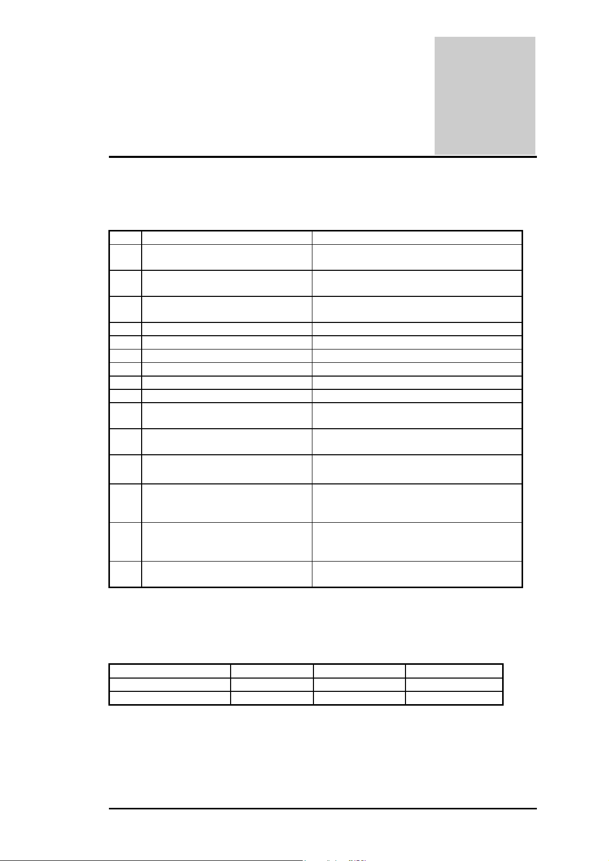
The pin assignment of the VGA connector is as follows:
CRT (VGA) Connector
CRT (VGA) ConnectorCRT (VGA) Connector
No PIN ASSIGEMENT(by: sort) DESCRIPTION
1 RED Video_5 :O
(analog)
2 GREEN Video_5 :O
(analog)
3 BLUE Video_5 :O
(analog)
4 Monitor ID Bit 2 Option
5 GROUND Ground
6 RED Return (ground) Ground
7 GREEN Return (ground) Ground
8 BLUE Return (ground) Ground
9 KEY (no connector) VCC
10 SYNC Return (ground)
11 MONITOR ID Bit 0_5
12 MONITOR ID Bit 1_5 :I DDC monitor data
Red this DAC analog output drives the
CRT interface.
Green this DAC analog output drives the CRT
interface.
Blue this DAC analog output drives the
CRT interface.
Ground
Monitor Sense Indicator
B
13 HORIZONTAL SYNC_5 :O
(t/s)
14 VERTICAL SYNC_5 :O
(t/s)
15 MONITOR ID Bit 3_5 :I/O
Absolute Maximum Conditions
The following parameters are maximum ratings for VGA. Permanent device damage may
occur if these rating are exceeded. Extended exposure to these ratings may also cause device
failure.
PARAMETER MIN MAX UNIT
I/O VOLTAGE -0.5 6.25V V
OUTPUT CURRENT 50 m A
CRT Horizontal Sync this output is
The Horizontal sync pulse for the
CRT Monitor.
CRT Vertical Sync this output is the
Vertical sync pulse for the CRT
Monitor.
DDC monitor clock
FIC A440 Series Service Manual B-1
Page 2

Pin Assignments
B.
B.2222 Serial Port Connector
B.B.
Serial Port Connector
Serial Port ConnectorSerial Port Connector
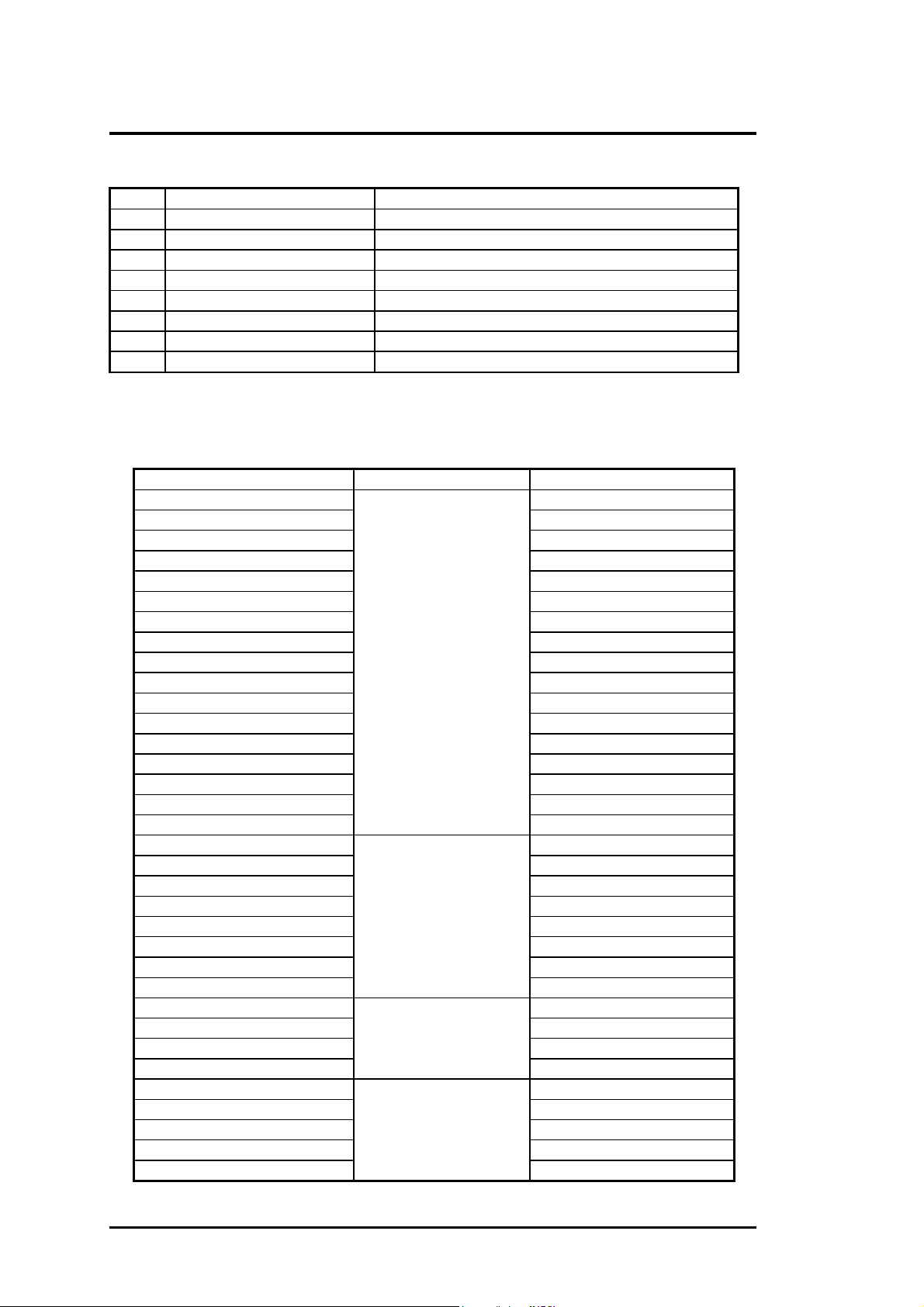
The pin assignment of the serial (COM1) port connector is as follows:
No PIN ASSIGMENT (by: sort) DESCRIPTION
1 DCDA#_T:I Active low Data Carrier Detect inputs
For the serial port.
2 SINA_T:I Receiver serial data input for port 1.
3 SOUTA_12:O Transmit serial data output for port 1.
4 DTRA#_6:O Active low Data Terminal Ready
Outputs for the serial port.
5 GND Ground
6 DSRA#_T:I Active low Data Set Ready inputs
For the serial port.
7 RTSA#_6:O Active low Request to Send Outputs
For the serial port.
8 CTSA#_T:I Active low Clear to Send inputs
For the serial port.
9 RI#_T:I Active low Ring Indicator inputs
For the serial port.
B.
B.3333 Parallel Port Connector
B.B.
Parallel Port Connector
Parallel Port ConnectorParallel Port Connector
The pin assignment of the parallel/printer (LPT1) port connector is as follows:
No PIN ASSIGMENT(by: sort) DESCRIPTION
1 STB#/DS0#_D14/_P14/_D12:O An active low pulse on this output is used to strobe the
printer data into the printer. The STROBE output is the
complement of bit 0 of the printer control register. Refer
to parallel port description for use
of this pin in ECP and EPP mode. Active low outputs
select driver 0.
2 PD0/INDEX3#_P14/_S:IO/I Port data 0.
This active low Schmidt trigger input senses from the
disk drive that the head is positioned over the beginning
of a track as marked by an index hole.
3 PD1/TRK0#_P14/_S:IO/I Port data 1
This active low Schmidt trigger input senses from the
disk drive that the head is positioned over the outermost
track.
4 PD2/WRTPRT#_P14/_S:IO/I Port data 2
This active low Schmidt trigger input senses from the
disk drive that a disk is write protected. Any write
command is ignored.
5 PD3/RDATA#_P14/_S:IO/I Port data 3
Raw serial bit stream from the disk drive, low active.
Each falling edge represents a flux transition of the
encoded data.
6 PD4/DSKCHG_P14/_S:IO/I Port data 4
This input senses that the driver door is open or that the
diskette has possibly been changed since the last drive
selection.
7 PD5_P14:IO Port data 5
B-2 FIC A440 Series Service Manual
Page 3

Pin Assignments
No PIN ASSIGMENT(by: sort) DESCRIPTION
8 PD6/MTR0#_P14/_D12:IO/O Port data 6
This active low outputs select motor Drives 0.
9 PD7_P14:IO Port data 7
10 ACK#/DS1#_T_D12:I/O A low active output from the printer indicating that it has
received the data and is ready to accept new data. Bit 6
of the printer status register reads the ACK# input. Refer
to parallel port description for use of this pin in ECP and
EPP mode.
11 BUSY/MRT1#_T/_D12:_I/O This is a status output from the printer, a high indicating
that the printer is not ready to receive new data. Bit 7 of
the printer status register is the complement of the
BUSY input. Refer to parallel port
Description for use of this pin in ECP and EPP mode.
This active low outputs select motor Drives 1.
12 PE/WDATA#_T/_D12:I/O Another status output from the printer, a high indicating
that printer is out of paper. Bit 5 of the printer status
register reads the PE input. Refer to parallel port
description for use of this pin in ECP and
EPP mode. This active low high current driver
Provide the encoded data to the disk drive. Each falling
edge cause a flux transfer on the media.
13 SLCT/WGATE#_T/_D12:I/O This high active output from the printer indicates that it
has power on. Bit 4 of the printer status register read the
SLCT input. Refer to parallel port description
For use of this pin in ECP and EPP mode.
This active low high current driver allows current to flow
through the write head.
It becomes active just prior to writing to the diskette.
14 AFD#/DSB#_D14,_P14/_D12:O
,O/O
15 ERR#/HDSEL_T/D12:I/O A low on this input from the printer indicates that there is
16 INIT#/DIR#_D14,_P14/D12:O,O
/O
17 SLIN#/STEP#_D14,_P14/_D12:
O,O/O
This output goes low to cause the printer to
automatically feed one line after each line is printed.
The AFD# output is the complement of bit 1 of the
printer control register. Refer to parallel pot description
for use of this pin in ECP and EPP mode.
a error condition at the printer. Bit 3 of the printer status
register reads the ERR# input. Refer to
Parallel port description for use of this pin in ECP and
EPP mode. This high current output selects the floppy
Disk side for reading or writing. A logic “1” on this pin
means side 0 will be accessed while a logic “0” means
side 1 will be accessed.
This output is bit 2 of the printer control register. This is
used to initiate the printer when low. Refer to parallel
port description for use of this pin in ECP and EPP
mode. This high current low active output determines
the direction of the head movement. A logic “1” on this
pin means outward motion, while a logic “0” means
inward motion.
This active low output selects the printer. This is the
complement of bit 3 of the printer control register. Refer
to parallel port description for use of this pin in
ECP and EPP mode. This active low high current driver
issues a low pulse for each track to track movement of
the head.
FIC A440 Series Service Manual B-3
Page 4
Pin Assignments
No PIN ASSIGMENT(by: sort) DESCRIPTION
18 GND: Ground
19 GND: Ground
20 GND: Ground
21 GND: Ground
22 GND: Ground
23 GND: Ground
24 GND: Ground
25 GND: Ground
B.
B.4444 Docking Port Replicator
B.B.
Docking Port Replicator
Docking Port ReplicatorDocking Port Replicator
The pin assignment of the port replicator connector is as follows:
Number Function Pin name
51 LPT_PD0
49 LPT_PD1
47 LPT_PD2
45 LPT_PD3
43 LPT_PD4
41 LPT_PD5
39 LPT_PD6
37
30
32
34
36
40
42 LPT_SLCT
44 LPT_ACK#
46 LPT_BUSY#
48
17 COM_PSOUTA
16 COM_PSINA
15 COM_PDTRA#
18 COM_PDSRA#
21 COM_PRTSA#
23 COM_PCTSA#
19 COM_PRIS/D#
20
57 EKB_DATA
59 EKB_CLK
58 MOUSE_DATA
60
3 CRT_RED
7 CRT_GREEN
5 CRT_BULE
4 CRT_HSYNC
8
Printer Port
COM Port
Ext K/B & PS2 Mouse
CRT
LPT_PD7
LPT_SLIN#
LPT_INIT#
LPT_ERR#
LPT_AFD#
LPT_PE
LPT_STB#
COM_PDCDA#
MOUSE_CLK
CRT_VSYNC
B-4 FIC A440 Series Service Manual
Page 5

Pin Assignments
Number Function Pin name
9 CRT_SENSE
6 DDDA
10
29 D-USBP0+
33 D-USBP0-
31
71,73,75,77,79 +5VS
68,70,72,74,76,78, 80 +ADAPV
13,14,26,27,35,38,
52,55,63,64,
61
67
1,2
PLUG IN Identified
CRT
USB Port
POWER
CONTROL
POWER
DDCK
OC0#
GND
ON MOSFET
+12VS
DOCKING POWER ENABLE
B.5
B.5 PS/2 Mouse / Ext. Keyboard Mini
B.5B.5
PS/2 Mouse / Ext. Keyboard Mini----DIN Connector
PS/2 Mouse / Ext. Keyboard MiniPS/2 Mouse / Ext. Keyboard Mini
DIN Connector
DIN ConnectorDIN Connector
Following is the pin assignment of the PS/2 connector:
No Signal Description Type
1 EKB_DATA External data for mouse or keyboard I/O
2 MOUSE_DATA External data for mouse or keyboard I/O
3 Gnd Ground I
4 +5vs 5v power supply O
5 EKB_CLK External clock for mouse or keyboard I/O
6 MOUSE_CLK External clock for mouse or keyboard I/O
B.
B.6666 USB Connector
B.B.
USB Connector
USB ConnectorUSB Connector
The pin assignment of the USB port connector is as follows:
No Signal Description Type
1, 5, 9, 10, 11,
12
2 USBP0+ USB port0 bus signal O
3 USBP0- USB port0 bus signal O
4 +5VS USB port0 power
6 USBP1+ USB port1 bus signal
7 USBP1- USB port1 bus signal
8 +5VS USB port1 power
GND Ground O
FIC A440 Series Service Manual B-5
Page 6

B.
B.7777 CD
B.B.
CD----ROM IDE Connector
CDCD
Pin Assignments
ROM IDE Connector
ROM IDE ConnectorROM IDE Connector
The following is the pin assignment for the CD-ROM IDE connector:
NO. Signal Description Type
5 CDROMRESET# Reset secondary disk O
33 RSDA0 Secondary disk address 0 O
31 RSDA1 Secondary disk address 1 O
34 RSDA2 Secondary disk address 2 O
21 RSDD0 Secondary disk data 0 I/O
19 RSDD1 Secondary disk data 1 I/O
17 RSDD2 Secondary disk data 2 I/O
15 RSDD3 Secondary disk data 3 I/O
13 RSDD4 Secondary disk data 4 I/O
11 RSDD5 Secondary disk data 5 I/O
9 RSDD6 Secondary disk data 6 I/O
7 RSDD7 Secondary disk data 7 I/O
6 RSDD8 Secondary disk data 8 I/O
8 RSDD9 Secondary disk data 9 I/O
10 RSDD10 Secondary disk data 10 I/O
12 RSDD11 Secondary disk data 11 I/O
14 RSDD12 Secondary disk data 12 I/O
16 RSDD13 Secondary disk data 13 I/O
18 RSDD14 Secondary disk data 14 I/O
20 RSDD15 Secondary disk data 15 I/O
35 RSDCS1# Secondary disk chip select for 100 range O
36 RSDCS3# Secondary disk chip select for 300 range O
28 RSDDACK# Secondary DMA acknowledge O
22 RSDDREQ Secondary DMA request I
24 RSDIOR# Secondary disk IO read O
25 RSDIOW# Secondary disk IO write O
27 RSIORDY Secondary disk IO channel ready I
29 IRQ15 Secondary disk interrupt I
50 DVDIN# DVD Insert I
49 CDIN# CDROM insert I
37 CDROMLED# CDROM access indicator O
2 CD_R CDROM sound right signal O
4 CD_LGND Right Ground I
1 CD_L CDROM sound left signal O
3 CD_RGND Left Ground I
39,41,38,40,
42
23,43,44,45,
46,48
+5Vs +5V power supply I
Gnd Ground O
B-6 FIC A440 Series Service Manual
Page 7

B.
B.8888 D
B.B.
DCCCC----IN Jack Pin Assignment
DD
Pin Assignments
IN Jack Pin Assignment
IN Jack Pin AssignmentIN Jack Pin Assignment
The pin assignment of the DC-IN connector is as follows:
No Signal Description Type
1 ADAPV+ Adapter input voltage I
2 Gnd Ground O
B.
B.9999 LCD Connector Pin Assignment
B.B.
LCD Connector Pin Assignment
LCD Connector Pin AssignmentLCD Connector Pin Assignment
The pin assignment of the LCD connector is as follows:
Pin Name Remark Pin Name Remark
1 GND 2 GND
3 LCD_P7D For DSTN LCD 4 GND
5 LCD_P7 For LVDS panel 6 LCD_L_P8
7 LCD_P6 For LVDS panel 8 LCD_L_P9
9 LCD_P6D For DSTN LCD 10 LCD_L_P10
11 GND 12 LCD_L_P11
13 LCD_P5D For DSTN LCD 14 GND
15 LCD_P5 For LVDS panel 16 LCD_L_P12
17 LCD_P4 For LVDS panel 18 LCD_L_P13
19 LCD_P4D For DSTN LCD 20 LCD_L_P14
21 GND 22 LCD_L_P15
23 LCD_P3D For DSTN LCD 24 GND
25 LCD_P3 For LVDS panel 26 LCD_L_P16
27 LCD_P2 For LVDS panel 28 LCD_L_P17
29 LCD_P2D For DSTN LCD 30 LCD_L_P18
31 GND 32 LCD_L_P19
33 LCD_P1D For DSTN LCD 34 GND
35 LCD_P1 For LVDS panel 36 LCD_L_P20
37 LCD_P0 For LVDS panel 38 LCD_L_P21
39 LCD_P0D For DSTN LCD 40 LCD_L_P22
41 GND 42 LCD_L_P23
43 GND 44 GND
45 +VLCD 46 +VLCD
47 +VLCD 48 +VLCD
49 GND 50 GPI5_PIIX4_LCDID0#
51 LCD_LCDSCLK 52 GPI19_PIIX4_LCDID1#
53 LCD_SFLM 54 GPI21_PIIX4_LCDID2#
55 GND 56 DIGON
57 LCD_SLP 58 LCD_BIASON
59 LCD_SDE 60 LCD_CONTRAST
61 GND 62 GND
63 LCD_INTVNA 64 GND
65 LCD_BRIGHTNESS 66 GND
67 +5VS_INVERT 68 +5VS_INVERT
69 +5VS_INVERT 70 +5VS_INVERT
FIC A440 Series Service Manual B-7
Page 8

B.
B.10
10 Fan Pin Assignment
B.B.
Fan Pin Assignment
1010
Fan Pin AssignmentFan Pin Assignment
Pin Assignments
The pin assignment of the internal fan is as follows:
No Signal No Signal
1 +5VS 2 GND
B.
B.11
11 AIO Board Pin Assignment
B.B.
AIO Board Pin Assignment
1111
AIO Board Pin AssignmentAIO Board Pin Assignment
The pin assignment of the AIO board is as follows:
No Signal No Signal
1, 2, 23, 24, 33,
36, 49, 50, 55,
60, 86, 87
3 PIDE_RPDCS3# 46 FDD_WP#
4 HDDLED# 47 FDD_RDATA#
5 PIDE_RPDA2 48 FDD_HDSEL#
6 PIDE_RPDCS1# 51 IR_TXD
7 PIDE_RPDD15 52 IR_RX1
8 PIDE_RPDA0 53 IR_RX2
9 PIDE_RPDD14 54 GPI13_PIIX4_FDDIN#
10 PIDE_RPDA1 56 SMDATA_KB
11 PIDE_RPDD13 57 PWRON
12 IRQ14 58 SMCLK_KB
13 PIDE_RPDD12 59 LED_CHARGE
14 PIDE_RPDDACK# 61 LS120IN#
15 PIDE_RPDD11 62 KB_X15
16 PIDE_RPIORDY 63 KB_X14
17 PIDE_RPDD10 64 KB_X13
18 PIDE_RPDIOR# 65 KB_X12
19 PIDE_RPDD9 66 KB_X11
20 PIDE_RPDIOW# 67 KB_X10
21 PIDE_RPDD8 68 KB_X9
22 PIDE_RPDDRQ 69 KB_X8
25 PIDE_RPDD0 70 KB_X7
26 PIDE_RPDD4 71 KB_X6
27 PIDE_RPDD1 72 KB_X5
28 PIDE_RPDD5 73 KB_X4
29 PIDE_RPDD2 74 KB_X3
30 PIDE_RPDD6 75 KB_X2
31 PIDE_RPDD3 76 KB_X1
32 PIDE_RPDD7 77 KB_X0
34 GPO6_PIIX4_HDDRESET# 78 KB_XY7
35 FDD_INDEX# 79 KB_XY6
37 FDD_DSKCHG# 80 KB_XY5
38 FDD_DR0# 81 KB_XY4
39 FDD_MTR0# 82 KB_XY3
40 FDD_DIR# 83 KB_XY2
41 FDD_3MODE 84 KB_XY1
42 FDD_STEP# 85 KB_XY0
GND 100, 99, 98, 97,
92, 94, 96, 95,
93
+5VS
B-8 FIC A440 Series Service Manual
Page 9

Pin Assignments
43 FDD_WDATA# 88 ACIN
44 FDD_WGATE# 89 IDA#
45 FDD_TRK0# 90 TERR
92,94 +3VS 91 LID_SW#
B.1
B.12222 Internal FDD Connector
B.1B.1
Internal FDD Connector
Internal FDD ConnectorInternal FDD Connector
The pin assignment for the FDD connector is as follows:
NO. Signal Description Type
3 RDATA# Read disk data. Raw serial bit stream form the disk drive,
low active. Each falling edge represents a flux transition
of the encoded data.
9 WGATE# Write gate. This active low high current driver allows
current to flow through the write head.
It becomes active just prior to writing to the diskette.
11 WDATA# Write data. This active low high current driver provides
the encoded data to the disk drive.
Each falling edge causes a flux transition on the media.
1 HDSEL# Head select. The high current select the floppy disk side
for reading or writing. A logic “1” on the pin means side 0
will be accessed, while a logic “0” means side 1 will be
accessed.
15 DIR# Direction control. This high current low active output
determines the direction of the head movement. A logic
“1” on this pin means outward motion, while a logic “0”
means inward motion.
13 STEP# Step pulse. The active low high current driver issues a
low pulse for each track-to-track movement of the head.
21 DSKCHG# Disk change. This input senses that the drive door is
open or that the diskette has possibly been changed
since the last drive selection.
This input is inverted and read via bit 7 of I/O address
3F7H. The DSKCHG# bit also depends upon the state of
the Force Disk Change bits in the Force FDD Status
Change configuration register.
23 DS0# Drive select 0. Active low outputs select drives 0. O
17 MOTR0 Motor on. These active low output motor on. O
14 3MODE 3 Mode FDD select. O
5 WRTPRT# Write protected. This active low Schmitt trigger input
senses from the disk drive that a disk is write protected.
7 TRK0# Track 00. This active low Schmitt trigger input senses
from the disk drive that the head is positioned over the
outermost track.
25 INDEX# This active low Schmitt Trigger input senses from the
disk drive that head is positioned over the beginning of a
track , as marked by an index hole.
16 READY FDD ready I
20 FDDIN# FDD insert I
2,4,6,8,10,12 Gnd Ground I
22,24,26 +5Vs +5V power supply O
18,19 NC No connection
I
O
O
O
O
O
I
I
I
I
FIC A440 Series Service Manual B-9
Page 10

Pin Assignments
B.
B.13
13 HDD
B.B.
The pin assignment of the internal HDD is as follows:
HDD Pin Assignment
1313
HDD HDD
PIN NUMBER PIN NAME PIN NUMBER PIN NAME
1 HD1RST# 2 GND
3 PDD7 4 PDD8
5 PDD6 6 PDD9
7 PDD5 8 PDD10
9 PDD4 10 PDD11
11 PDD3 12 PDD12
13 PDD2 14 PDD13
15 PDD1 16 PDD14
17 PDD0 18 PDD15
19 GND 20 NC
21 PDDREQ 22 GND
23 PDIOW# 24 GND
25 PDIOR# 26 GND
27 PIORDY 28 CSEL
29 PDDACK# 30 GND
31 IRQ14 32 NC
33 PDA1 34 PDIAG#
35 PDA0 36 PDA2
37 PDCS1# 38 PDCS3#
39 HDDLED# 40 GND
41 +5VHDS1 42 +5VHDS1
43 GND 44 NC
Pin Assignment
Pin AssignmentPin Assignment
B.14
B.14 B+ of
B.14B.14
The pin assignment of the B+ 12V is as follows:
B.1
B.15555 Internal Keyboard FPC Conn
B.1B.1
The pin assignment of the internal keyboard connector is as follows:
B+ of 12
B+ of B+ of
No Signal Description Type
1,2,3,4,5,6 B+ Power O
8 NU Key NC
7,9,10, 11,12 GND Ground O
Internal Keyboard FPC Connector
Internal Keyboard FPC ConnInternal Keyboard FPC Conn
No Signal Description Type
1 X15 Keyboard matrix column 15 I
2 X14 Keyboard matrix column 14 I
3 X13 Keyboard matrix column 13 I
4 X12 Keyboard matrix column 12 I
5 X11 Keyboard matrix column 11 I
6 X10 Keyboard matrix column 10 I
7 X9 Keyboard matrix column 9 I
8 X8 Keyboard matrix column 8 I
9 X7 Keyboard matrix column 7 I
12 PPPPin
in AAAAssignment
12 12
ssignment
in in
ssignmentssignment
ector
ectorector
B-10 FIC A440 Series Service Manual
Page 11

Pin Assignments
10 X6 Keyboard matrix column 6 I
11 X5 Keyboard matrix column 5 I
12 XY7 Keyboard matrix row 7 O
13 XY6 Keyboard matrix row 6 O
14 XY5 Keyboard matrix row 5 O
15 XY4 Keyboard matrix row 4 O
16 X4 Keyboard matrix column 4 I
17 X3 Keyboard matrix column 3 I
18 XY3 Keyboard matrix row 3 O
19 XY2 Keyboard matrix row 2 O
20 XY1 Keyboard matrix row 1 O
21 XY0 Keyboard matrix row 0 O
22 X2 Keyboard matrix column 2 I
23 X1 Keyboard matrix column 1 I
24 X0 Keyboard matrix column 0 I
B.1
B.16666 Battery Connector
B.1B.1
Battery Connector
Battery ConnectorBattery Connector
The pin assignment for the battery connector is as follows:
No Signal Description Type
8 Gnd Ground I
7 TH Thermal sensor I
6 DTA SMBus data signal I/O
5 CLK SMBus clock signal I/O
4 SEL Not used 3 ID2 Battery insert detection O
2 ID1 Not Used 1 BAT+ Battery output/input voltage I/O
BBBB.1
.17777 AAAAudio B
.1.1
No Signal No Signal
1 GND 2 +5VS
3 +3VS 4 +5VS
5 PDAMP# 6 CD_GND
7 SUSLED# 8, CD_L
9 CHGLED 10 CD_R
11 MBATW# 12 CD_GND
13 BATL# 14 ZV_SDATA
15 GND 16 ZV_SCLK
17 NC 18 ZV_RCLK
19 NC 20 ZV_MCLK
21 +5V 22 +5VS
23 GLIDPAD_CLK 24 NC
25 GLIDPAD_DATA 26 C24
27 GND 28 GND
29 INTAC97RST# 30 SDFSO
31 AUDSCLK 32 PCIRST#
33 NC 34 SDATA_IN
udio Board
udio Budio B
oard PPPPin
oard oard
in AAAAssignmen
ssignmentttt
in in
ssignmenssignmen
FIC A440 Series Service Manual B-11
Page 12

Pin Assignments
35 BEEP 36 SDATA_OUT
37 GND 38 GND
39 +RTCBAT 40 +12VS
B.1
B.18888 Audio Jack
B.1B.1
The audio jack comprises of the headphone jack, line-out jack, and microphone jack:
Audio Jack
Audio JackAudio Jack
Headphone Jack
The pin assignment of the headphone jack is as follows:
No Signal Description Type
1 GND Ground I
2 HP_L Headphone left sound O
3 HP_R Headphone right sound O
4 AMPCTRL Amplifier control signal I
5 GNDP Pull-down signal O
6 NC Not used -
Line-In Jack
The pin assignment of the line-in jack is as follows:
No Signal Description Type
1 GND Ground I
2 LINEINL Line in left sound O
3 GND Ground I
4 GND Ground I
5 LINEINR Line in right sound O
Microphone Jack
The pin assignment of the microphone jack is as follows:
No Signal Description Type
1 GND Ground I
2 MICIN External Microphone input signal I
3 INTMIC Internal microphone signal O
4 NC Not used 5 NC Not used -
BBBB.1
.19999 Internal M
Internal Microphone
.1.1
Internal MInternal M
The pin assignment of the internal microphone is as follows:
No Signal Description Type
1 MICIN External Microphone input signal
2 GND Ground
icrophone CCCConnector
icrophoneicrophone
onnector
onnectoronnector
B-12 FIC A440 Series Service Manual
Page 13

Pin Assignments
BBBB
.20 Internal Left Speaker Connector
.20 Internal Left Speaker Connector
.20 Internal Left Speaker Connector.20 Internal Left Speaker Connector
The pin assignment of the internal left speaker is as follows:
No Signal Description Type
1 L_OUT+ Speaker signal
2 L_OUT- Speaker signal
3 R_OUT+ Speaker signal
4 R_OUT- Speaker signal
BBBB....22221111 RTC
The pin assignment of the RTC battery is as follows:
BBBB.2
RTC Battery
RTC RTC
No Signal Description Type
1 +RTCBAT RTC Battery Power
2 GND Ground
.22222 GGGGlidepad
.2.2
Battery
BatteryBattery
lidepad Connector
lidepadlidepad
Connector
ConnectorConnector
The pin assignment of the glidepad is as follows:
No Signal Description Type
1 +5VS +5V POWER
2 DATA Data Signal
3 CLK Clock Signal
4 SW-R Switch Right
5 SW-L Switch Left
6 GND Gound
BBBB.2
.23333 SSSS----VVVVideo Co
.2.2
The pin assignment of the S-Video connector is as follows:
No Signal Description Type
1 GND Ground
2 GND Ground
3 Y Luminance O/P
4 C Chrominance O/P
ideo Connector
ideo Coideo Co
nnector
nnector nnector
FIC A440 Series Service Manual B-13
 Loading...