

Page 1

FIC A360 Intel® FC-PGA Pentium-III / Celeron Notebooks
A360 Model
Reference and
Service Manual
Page 2

Legal Notice
Information in this document is subject to change without notice. Please contact FIC Portable
Computing Group (PCG) Customer Service Dept. for the latest editions of this manual.
Furthermore, FIC does not make any representations or warranties (implied or otherwise)
regarding the accuracy and completeness of this document and shall in no event be liable for
any loss of profit or any other commercial damage, including but not limited to special,
incidental, consequential, or other damages.
Copyright (©) 2001 FIC, Inc.
LL RIGHTS RESERVED - Printed in Taiwan.
A
No part of this document may be reproduced or transmitted in any form by any means,
electronic or mechanical, including photocopying, recording or information recording and
retrieval systems without the express written permission of FIC.
All brand names and product names used in this document are trademarks, or registered
trademarks of their respective holders.
How to Contact FIC Portable Computing Group
PCG WEB SITE
FIC Portable Computing Group
FIC HOMEPAGE
First International Computer, Inc.
SALES & MARKETING
E-mail:
TECHNICAL SUPPORT
E-mail:
CUSTOMER SERVICE (RMA)
E-mail:
COMPILER:Tech. Support
E-mail:
http://pcg.fic.com.tw
http://www.fic.com.tw
marketing@pcg.fic.com.tw
pcg_csd_technical_support@pcg.fic.com.tw
pcg_csd_customer_support@pcg.fic.com.tw
pcg_csd_technical_support@pcg.fic.com.tw
Page 3

FIC A360 MODEL
INTEL FC-PGA PENTIUM-III / CELERON NOTEBOOKS
Reference and Service Manual
July 2001, Volume 1
First International Computer, Inc.
Portable Computing Group
7F, #266, Wen-Hua 2 Rd., Linko, 244
Taipei, Taiwan, R.O.C.
Page 4

Preface
This manual contains operation, specifications, technical references, maintenance and
troubleshooting instructions for the FIC A360 notebook.
Intended Audience
This manual is primarily intended for use by qualified service technicians assigned to FIC
notebook PC repair operations. However, several sections contain overview technical
information useful to a general (less-technical) audience.
Contents
This manual contains the following:
• Chapter 1: Outline of the A360 - Introduces the notebook and identifies all standard and
optional features including outlines on the BIOS SETUP program.
• Chapter 2: Installation and Upgrade - Provides information on installing the device drivers
and utility programs of the notebook as well as important system upgrade procedures.
• Chapter 3: Software Functional Overview - Provides a functional overview of the
notebook’s BIOS and software operation. This includes the power management function and
system resource listing.
• Chapter 4: Hardware Functional Overview - Provides a functional overview of the
notebook’s hardware and sub-assemblies as well as description of every component and
chipset used to control each operation.
• Chapter 5: Maintenance & Disassembly - Describes the preventive and corrective
maintenance procedures for the notebook. This includes primarily the disassembly and
assembly procedures of the notebook.
• Chapter 6: Troubleshooting and Repair - Provides instructions in handling BIOS POST
Error codes and messages as well as guidelines in doing board-level troubleshooting.
• Appendix A: Notebook Specification - Provides detailed information on the entire
notebook’s specification including system specification, mechanical specification, and
environmental specification.
• Appendix B: Pin Assignment - Contains lists of all pin assignments for ports, connectors, and
slots.
• Appendix C: FRU Parts Listing - Contains lists of field replaceable parts for RMA purpose.
Page 5

T able of Contents
Preface
Chapter 1 Outline of the A360
1.1 Introduction / 1-1
1.2 Feature Highlights / 1-1
1.3 System Configuration / 1-4
1.4 Quick Tour of the Notebook / 1-5
1.4.1 Inside the Notebook / 1-5
1.4.2 Front Side of the Notebook / 1-11
1.4.3 The Right Side of the Notebook / 1-12
1.4.4 The Left Side of the Notebook / 1-13
1.4.5 The Rear Side of the Notebook / 1-15
1.4.6 The Under Side of the Notebook / 1-17
1.5 System BIOS SETUP Program / 1-18
1.5.1 Using the Main Menu / 1-19
1.5.2 Using the Advanced Menu / 1-21
1.5.3 Using the Security Menu / 1-25
1.5.4 Using the Boot Menu / 1-26
1.5.5 How to Exit the Setup Program / 1-27
1.6 Notebook Accessories and System Options / 1-28
1.6.1 AC Adapter and Power Cord / 1-28
1.6.2 Battery Pack / 1-28
1.6.3 Car Cigarette Power Cable / 1-28
1.6.4 Internal Modem Module / 1-28
1.6.5 Internal Ethernet LAN Module / 1-28
1.6.6 DVD-ROM Drive / 1-28
1.6.7 CD-RW Driver / 1-29
1.6.8 Audio-DJ / 1-29
Chapter 2 Installation and Upgrade
2.1 Overview / 2-1
2.2 Notebook Drivers and Utilities / 2-1
FIC A360 Service Manual i
Page 6

T able of Contents
2.2.1 Running the PHDISK STD Utility / 2-1
2.2.2 Installing Windows 98 / Me / 2000 from CD / DVD
ROM / 2-2
2.2.3 Installing the VGA Device Driver / 2-2
2.2.4 Installing the Audio Device Driver / 2-3
2.2.5 Installing EzSystem Driver / 2-3
2.2.6 Installing Touch Pad Driver / 2-4
2.2.7 Installing the Internal Modem / 2-4
2.2.8 Installing the Internal LAN / 2-6
2.2.9 Installing the Internal Como Modem / LAN / 2-7
2.3 System Upgrades / 2-8
2.3.1 Jumper Settings / 2-8
2.3.2 CPU Upgrade Procedure / 2-9
2.3.3 Memory Upgrade Procedure / 2-11
2.3.4 Hard Disk Upgrade Procedure / 2-12
2.3.5 System BIOS Upgrade Procedure / 2-14
Chapter 3 Software Functional Overview
3.1 Overview / 3-1
3.2 Summary of the BIOS Specification / 3-1
3.3 Subsystem Software Functions / 3-2
3.3.1 Key Chipset Summary / 3-2
3.3.2 System Memory / 3-3
3.3.3 Video / 3-3
3.3.4 Enhanced IDE / 3-5
3.3.5 Audio / 3-6
3.3.6 Super I/O / 3-6
3.3.7 PCMCIA / 3-6
3.3.8 LED Indicator / 3-6
3.3.9 Hot Keys Definition / 3-7
3.3.10 Plug & Play / 3-7
3.3.11 PCI Device / 3-8
3.3.12 SMBus Devices / 3-9
3.3.13 Resource Allocation / 3-9
3.3.14 GPIO Pin Assignment / 3-11
3.3.15 Intel PIIX4M GPI Signal / 3-13
ii FIC A360 Service Manual
Page 7

T able of Contents
3.3.16 Intel PIIX4M GPO Signal / 3-13
3.3.17 PMU07 GPIO Signal / 3-14
3.3.18 A550L Super I/O 37N869 GPIO Pin Definition /3-14
3.3.19 M38867 GPIO Signal / 3-15
3.4 Power Management / 3-15
3.4.1 General Requirements / 3-15
3.4.2 System Power Plane / 3-15
3.5 ACPI / 3-16
3.5.1 General Requirements / 3-16
3.5.2 System Power Plane / 3-16
3.5.3 Global System State Definitions / 3-16
3.5.4 Device Power State Definitions / 3-17
3.5.5 Sleeping State Definitions / 3-18
3.5.6 Power States / 3-19
3.5.7 Power States transition event / 3-19
3.5.8 Lid Switch / 3-20
3.5.9 Power Button and Internet / Mail Button / 3-20
3.5.10 Device Power Management / 3-20
3.5.11 Expanding Event Through the Embedded Controller
/ 3-22
3.5.12 Thermal Control / 3-24
3.5.13 Hardware Thermal Events / 3-26
3.5.14 Active Cooling Strength / 3-26
3.5.15 Passive Cooling Equation / 3-27
3.5.16 Critical Shutdown / 3-28
3.5.17 Other Implementation Of Thermal Controllable
Devices / 3-28
3.5.18 Thermal Control Methods / 3-29
3.5.19 AC Adapters and Power Source Objects / 3-31
3.6 Battery Management / 3-31
3.6.1 Battery Sub-system / 3-31
3.6.2 Battery Warning / 3-31
3.6.3 Battery Low / 3-31
3.6.4 AC Adapter / 3-32
3.7 PMU07 / 3-32
3.7.1 The System EC RAM with PMU07 / 3-32
FIC A360 Service Manual iii
Page 8

T able of Contents
3.7.2 PMU07 EC RAM List / 3-33
3.8 Miscellaneous / 3-41
3.8.1 Security / 3-41
3.9 CMOS Setup Utility / 3-41
Chapter 4 Hardware Functional Overview
4.1 Overview / 4-1
4.2 System Hardware Block Diagram / 4-2
4.4 System Processor (CPU) / 4-3
4.4.1 Intel Mobile Pentium-III Features / 4-3
4.4.2 Intel Mobile Celeron Features / 4-4
4.5 System Core Logic / 4-5
4.5.1 82443ZX Features / 4-5
4.5.2 82371MB (PIIX4M) Features / 4-6
4.6 Clock Frequency Generator / 4-8
4.7 Cache Memory / 4-8
4.8 System Memory / 4-8
4.8.1 System Memory / 4-8
4.8.2 Video Memory / 4-8
4.9 System BIOS / 4-8
4.10 Video Subsystem / 4-9
4.10.1 Video Chip Controller / 4-9
4.10.2 Video Clock / 4-9
4.11 I/O Subsystem / 4-9
4.12 PCMCIA Controller / 4-10
4.13 Audio Subsystem / 4-11
4.14 Keyboard and Pointing Device / 4-13
4.15 Disk Drives Subsystem / 4-14
4.16 Power Subsystem / 4-14
4.16.1 AC Power Adapter / 4-14
4.16.2 Internal Battery Pack / 4-14
4.16.3 DC-DC Module of Motherboard / 4-14
4.16.4 LCD Inverter Board Assembly / 4-14
4.17 Micro-P Subsystem (PMU-07) / 4-15
iv FIC A360 Service Manual
Page 9

T able of Contents
Chapter 5 Maintenance & Disassembly
5.1 Introduction / 5-1
5.2 Preventive Maintenance / 5-1
5.2.1 Cleaning the Computer / 5-1
5.2.2 Protecting the Disk Drives / 5-1
5.2.3 Maintaining the LCD Quality / 5-1
5.2.4 Maintaining the Hard Disk Drive / 5-2
5.2.5 Handling the Computer Battery Packs / 5-2
5.3 Required Tools and Equipment / 5-3
5.4 Notebook Field-Replaceable Parts and Assemblies / 5-3
5.4.1 Cover-Display LCD assembly / 5-4
5.4.2 System Unit Assembly / 5-4
5.5 Parts Removal and Replacement Procedures / 5-6
5.5.1 Removing the Battery Pack / 5-6
5.5.2 Removing the Keyboard / 5-6
5.5.3 Removing the LCD Panel / 5-7
5.5.4 Removing the Internal Hard Disk Drive / 5-9
5.5.5 Removing the Heat Sink Plate and Cooling Fan/5-10
5.5.6 Removing the CD-ROM Module / 5-10
5.5.7 Removing the System Top Cover / 5-11
5.5.8 Removing the Glide Pad / 5-12
5.5.9 Removing the Audio Board / 5-13
5.5.10 Removing the Battery Board / 5-14
5.5.11 Removing the Internal Speakers / 5-14
5.5.12 Removing the FDD Module / 5-15
5.5.13 Removing the CPU / 5-16
5.5.14 Removing / Replacing the Motherboard / 5-17
Chapter 6 Troubleshooting and Repair
6.1 Introduction / 6-1
6.1.1 Helpful Starters / 6-1
6.2 System BIOS Related Problems / 6-1
6.2.1 POST Messages / 6-1
6.2.2 Informational Messages / 6-4
FIC A360 Service Manual v
Page 10

T able of Contents
6.2.3 Beep Codes / 6-4
6.2.4 Run-time Error Messages / 6-9
6.3 Quick Troubleshooting / 6-10
6.4 Component-Level Troubleshooting / 6-13
6.4.1 General Overview / 6-13
6.4.2 Starting Check / 6-14
6.4.3 Memory Interface Check / 6-14
6.4.4 CRT Interface Check / 6-15
6.4.5 FDD Interface Check / 6-15
6.4.6 HDD Interface Check / 6-16
6.4.7 Internal Keyboard Check / 6-16
6.4.8 Glide pad Interface Check / 6-17
6.4.9 CD-ROM Interface Check / 6-17
6.4.10 Charger Board Interface Check / 6-18
6.4.11 Serial Port Interface Check / 6-18
6.4.12 External Keyboard Check / 6-19
6.4.13 PS/2 Mouse Interface Check / 6-19
6.4.14 Printer Port Interface Check / 6-20
6.4.15 Audio Port Interface Check / 6-20
6.4.16 PCMCIA Interface Check / 6-21
6.4.17 USB Port Interface Check / 6-21
6.4.18 DC-DC Power Check / 6-22
6.4.19 LCD Panel Interface Check / 6-22
6.4.20 Suspend Function Check / 6-23
6.4.21 LED Indicator Function Check / 6-24
6.4.22 Cover Switch Function Check / 6-25
6.4.23 Internal Modem or LAN Port Check / 6-25
6.4.24 Internal Combo Modem / LAN Port Check / 6-26
6.4.25 FIR Interface Check / 6-26
6.4.26 IEEE1394 Interface Check / 6-27
6.4.27 TV-Out Interface Check / 6-27
Appendix A Notebook Specification
A.1 System Specification / A-1
A.2 Display Specification /A-4
vi FIC A360 Service Manual
Page 11

T able of Contents
A.3 Floppy Disk Drive Specification /A-6
A.4 CD-ROM Drive Specification /A-7
A.5 DVD-ROM Drive Specification /A-7
A.6 CD-RW Drive Specification /A-8
A.7 Keyboard Specification /A-8
A.8 Touch Pad Specification /A-8
A.9 Internal Modem Specification /A-9
A.10 Internal LAN Specification /A-9
A.11 Power Supply /A-9
A.12 Inverter Specification /A-10
A.13 DC/DC Specification /A-10
A.14 Charger Specification /A-11
A.15 Mechanical Specification /A-11
A.16 Environmental Requirements /A-11
Appendix B Pin Assignments
B.1 CRT (VGA) Connector / B-1
B.2 Serial Port Connector / B-2
B.3 Parallel Port Connector / B-2
B.4 PS/2 Mouse / Ext. Keyboard Mini-DIN Connector / B-4
B.5 USB Connector / B-4
B.6 CD-ROM IDE Connector / B-4
B.7 DC-IN Jack Pin Assignment / B-5
B.8 LCD Connector Pin Assignment / B-5
B.9 FDD Connector / B-6
B.10 HDD Pin Assignment / B-6
B.11 Internal Keyboard FPC Connector / B-7
B.12 Battery Connector / B-7
B.13 Audio Jack / B-8
B.14 Internal Microphone Connector / B-8
Appendix C FRU Parts Listing
FIC A360 Service Manual vii
Page 12

Chapter
Outline of the A360
1.1 Introduction
This chapter provides the outline features and operation of the A360 including the BIOS
Setup program and other system options.
The A360 all-in-one notebook offers the latest in advanced portable computing and
multimedia technology that even outperforms most desktop computers. It incorporates the
latest Intel Pentium-III FC-PGA 370 Processor or Intel Celeron FC-PGA 370 processor and
fully compatibles with an entire library of PC software based on operating systems such as
MS-DOS, Windows 98/Me, and Windows NT/2000. It also runs on future versions of
Windows. It comes with a built-in Windows 98/Me keyboard, glide pad pointing device,
sound system, PCMCIA slots, USB (Universal Serial Bus) port, IEEE 1394 port, advanced
power management and more new multimedia features.
1.2 Feature Highlights
The A360 includes a variety of innovative features:
Features Description
CPU
Cache Memory
Bus Architecture
Bus Speed
System Memory
Display
VGA
Intel ® Pentium-III,
packaging at 933 MHz/1GHz/1.13GHz+ for Pentium-III at
766/800/850/900/950
• On-die secondary level cache (256-KB) for Pentium- III, Tualatin
• On-die secondary level cache (128-KB) for Celeron
32-bit PCI / PCI-to-ISA Bus Architecture
100 / 133 MHz Front Si de B us
• Two memory slots for 144-pin SODIMM SDRAM (3.3V)
• Use PC-100/133 SDRAM (64 / 128 / 256 MB)
• Upgradeable to 512 MB
• 12.1” SVGA TFT Color LCD at 800x600 pixel resolution
• 13.3"/14.1” XGA TFT Color LCD at 1024x768 pixels resolution
• Maximum 32-bit True Color display at 1024x768 pixel resolution
• Brightness controls via hot-key function
• LVDS Interface
• High performance S3 Savage4 (Integrated in Twister) with AGP
4X and SMA support.
• 0/8/16/32 MB VRAM sharing from SDRAM (Using system
memory; SMA Technology) (Twister spec is 2~32 MB).
• Up to 1280x1024 resolution for external CRT mo nitor at 16M
colors (32-bit Tr ue C olor)
• 128bit Graphics Engine
• Support Dual View and Dual Video
Celeron Processors using FC-PGA 370
+ MHz for Celeron
1
Formatiert: Nummerierung und
Aufzählungszeichen
FIC A360 Service Manual 1-1
Page 13

Outline of the A360
HDD
CD-ROM /
DVD-ROM /
CD-RW
FDD
Keyboard
Pointing Device
PCMCIA Slot
I/O Port
Audio System
• Built-in (internal) 2.5-inch Format; 9.5mm in Height Enha nced
IDE hard drive
• Supports Bus Mastering Ultra-DMA 33/66 feature fo r LBA
• Built-in ATAPI IDE 24X+ Speed CD-ROM drive; or
• Built-in ATAPI IDE 8X+ Speed DVD-ROM drive; or
• Built-in ATAPI IDE 4X+ Speed CD-RW drive; or
• Built-in ATAPI IDE Combo CD/DVD/CD-R/CD-RW drive
Built-in 3.5-inch 1.44MB floppy disk drive
• 19mm Pitch and 3mm Travel
• Built-in 87 / 90-key Windows keyboard
• Compatible with IBM enhanced 101 / 102-key keyboard
• Integrated Touch pad (Glide pad) with 2 select click buttons and
1 scroll button
• PS/2 mouse interface
• Double-deck PCMCIA 2.1 card slots that support two Type II or
one Type III PC cards
• 32-bit CardBus PCI local bus technology / Supports mixed
voltage PC cards (5V and 3.3V)
Includes the fo l lowing standard I/O ports:
•
9 1 x 9-pin Serial Port (COM1)
9 1 x 25-pin Printer Port (LPT1)
9 1 x DC-in Jack
9 1 x mini-DIN 6-pin PS/2 Por t (K/B or Mouse)
9 1 x 15-pin VGA Port (CRT)
9 2 x standard USB 1.1 Ports
9 1 x RCA TV-Out
9 1 x IEEE1394 Port (Reserved)
9 1 x IR Port (Reserved)
• 16-bit full-duplex sound controller with Woofer (heavy bass) voice
output, software wavetable function, and FM stereo synthesizer.
• Compatible with Sound Blaster and Sound Blaster Pro
• Integrated 2-way high quality paper cone stereo speakers (>1W)
with sound boxes and mono microphone
• Supports optional Audio-DJ to play audio CD like CD player
without powering on the whole computer.
• Includes the following:
9 Microphone-in jack (MIC-IN)
9 Headphone / Audio line-out jack (S/PDIF OUT)
• Volume thumb-wheel knob control
Gelöscht: /100
Formatiert
1-2 FIC A360 Servic e Manual
Page 14

Outline of the A360
Features Description
Power System
Power
Management
LED Indicator
Optional Module
• Universal Auto-switching 60W/65W AC Adapter (100V – 240V) /
Auto-charging capability
• Rechargeable Ni-MH (4500mAh/9.6V) / Li-Ion (3800mAh/14.4V)
Battery Pack
• Battery Life: 2 ~ 2.5 hours (Power Management Off)
• Charging Time: 2.5 ~ 3 hours quick charge (computer off)
• ACPI 1.0B Ready
• SMM (Intel System Management Mode) fully supported
• Suspend-to-RAM and Suspend-to-Disk feature Suspend hot-key
function / Battery Low Auto Suspend
• Cover Switch (Suspend/CRT -only) function
8 x LED Status Indicators for Power Source, Battery Charge, EMail, IDE, FDD, Caps Lock, Scroll Lock, Num Lock (LCD x 3 +
Machine Base x 5)
• 56Kbps Fax / Data Internal Modem with V.90 support
• 10 Base-T / 100 Base-TX LAN Mini PCI
• Combo Modem / LAN Mini-PCI
• Bluetooth Module
• DVD-ROM Device Pack
• CD-RW Device Pack
• Combo DVD / CD-RW Device Pack
• Audio DJ Panel
• USB Port Replicator
Gelöscht: / Auto
FIC A360Service Manual 1-3
Page 15
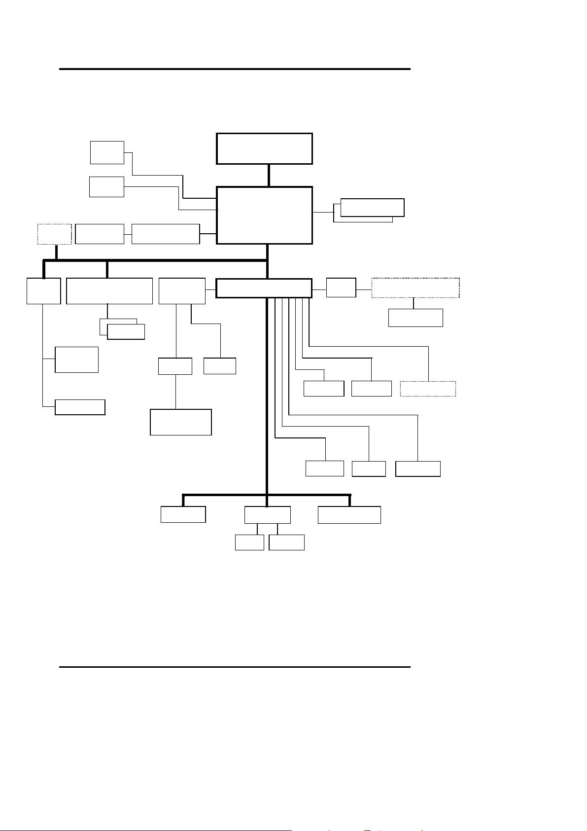
1.3 System Configuration
LCD
LVDS
CRT
1394 TV-Encodec
Mini
TV-OUT
CardBus
Combo
Headphone
Figure 1-1 System Config uration Diagram
Outline of the A360
Intel FC-PGA
CODEC
PMU07
Celeron /
VIA Twister
+ S3 Savage4
VT82C686B
MIC Amp
ISA_BUS
Pentium III
GTL_BUS
PCI_BUS
KBC Flash ROM
SDRAM
IDE
Audio DJ (OZ168)
CD-ROM
1-4 FIC A360 Servic e Manual
Page 16
Outline of the A360
1.4 Quick Tour of the Notebook
Please take a moment to become familiar with the location and purpose of every control, the
LED status panel, connectors and ports, which are illustrated in this section. It is
recommended to first go through the User Guide of the notebook, which is shipped together
with the notebook for information on how to operate its features.
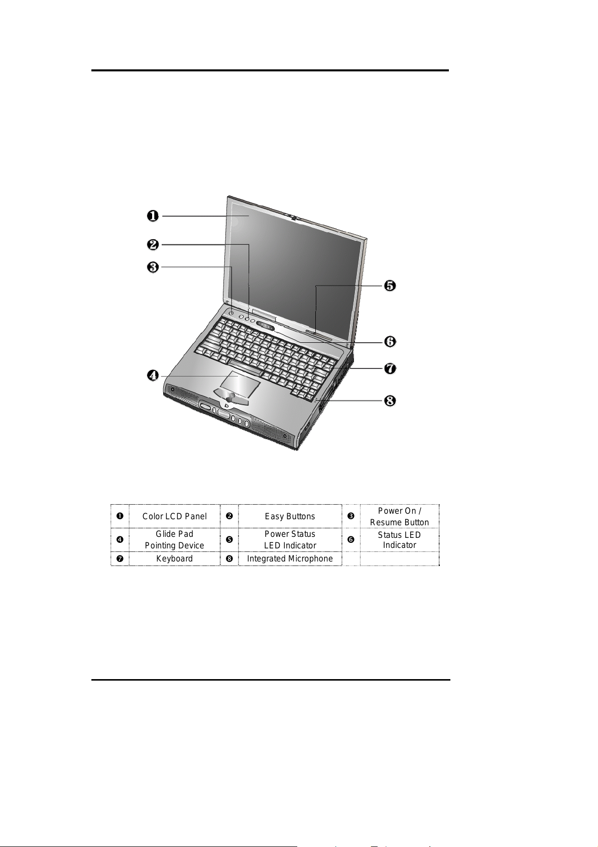
1.4.1 Inside the Notebook
To open the LCD cover of the notebook, find the cover latch located at the front center of the
LCD cover. Push the latch to the right to release and tilt the LCD cover up. Ins ide , yo u wil l
see the LCD display panel, keyboard, touch pad, status LED, and power switch.
Color LCD Panel
n
q
Pointing Device
t
Glide Pad
Keyboard
o
r
u
Figure 1-2 Inside the Notebook
Easy Buttons
Power Status
LED Indicator
Integrated Microphone
p
s
Power On /
Resume Button
Status LED
Indicator
Color LCD Display Panel
The notebook comes with several LCD option sizes at SVGA (800x600) or XGA (1024x768)
active-matrix TFT color liquid cryst a l disp la y (LC D). The LCD can be a 12.1” TFT (Thin
Film Transistor) color LVDS with 800x600 SVGA (Super Video Graphics Array) resolution
panels, or 13.3” or 14.1” TFT color LVDS with 1024x768 XGA (Extended Graphics Array)
FIC A360Service Manual 1-5
Page 17
Outline of the A360
resolution panels. You can adjust and tilt (up to 180o) the LCD screen panel to your desired
viewing position.
The notebook uses S3 4X AGP VGA graphics controller that owns maximum 32MB video
memory with SMA technology. All LCD models can support 16M colors or maximum 32-bit
true color at 1024x768 resolution. The notebook also supports simultaneous display of the
LCD with the external VGA monitor.
The LCD screen also uses CCFT (Cold Cathode Fluorescent Tube) backlighting which
consumes much of the electrical power of the notebook. To save battery power, the system
has an advanced power management feature that switches off the LCD when there is no
system activity for a predetermined amount of time.
You adjust the brightness level of the LCD by pressing the display control hot-keys. You
activate the hot-keys by pressing the <Fn> key along with another function key:
• <Fn> + <F8>
• <Fn> + <F9>
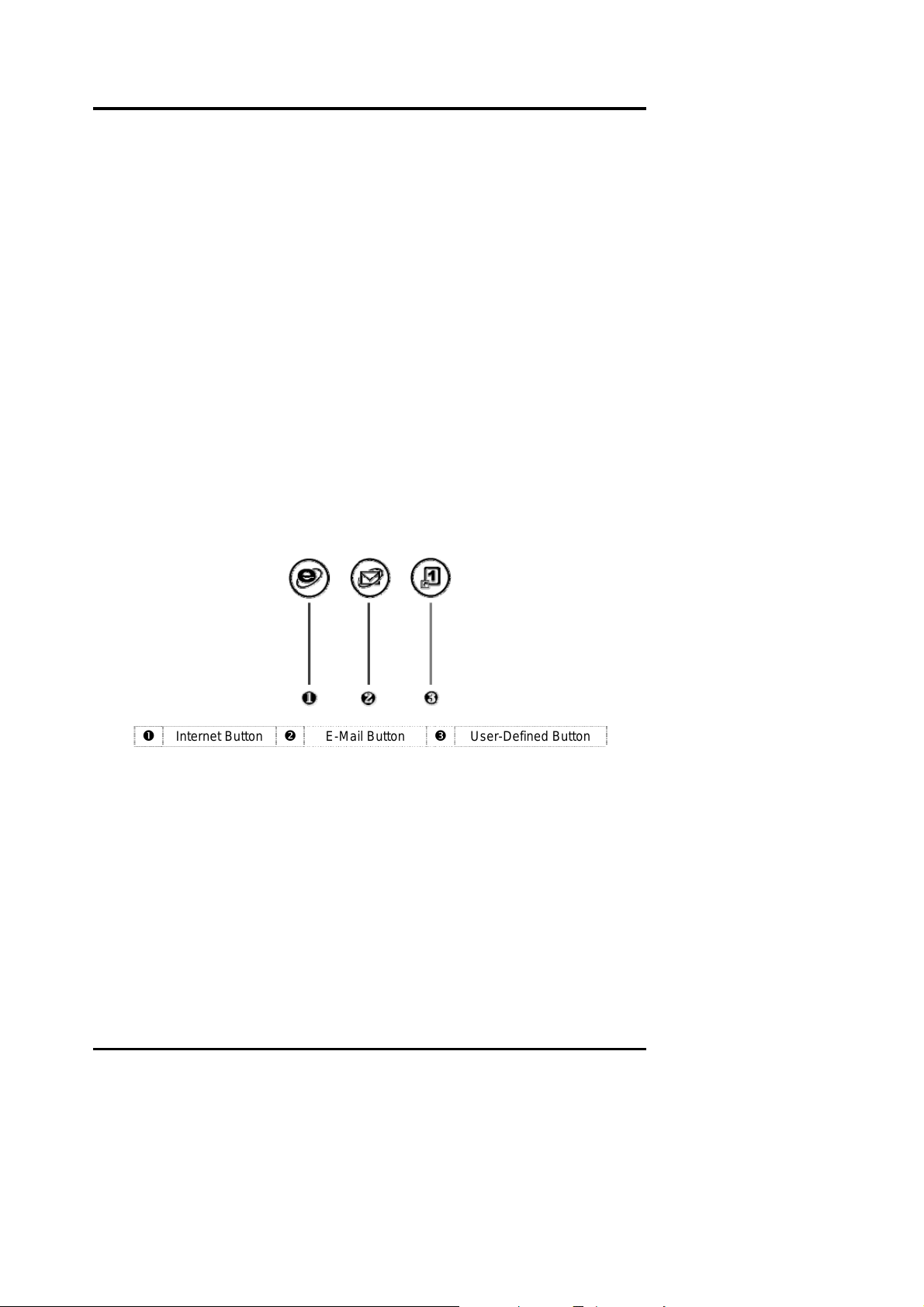
Easy Buttons
There are three easy buttons, two use for accessing Internet and e-mail functions instantly and
easily, the other one lets you define certain functions by yourself. Descriptions of the easy
buttons appear in the latter part of this section.
Key = Increases the brightness of the LCD display
Key = Decreases the brightness of the LCD display
Internet Button
n
− Internet Button
This technology is designed specifically for providing a very convenient way
in connecting Internet only by pressing Internet button as shown in the
graphics. For more understanding and interesting, you can refer Section 2.5
of user manual to recognize the driver installation procedures in activating
Internet button.
− E-mail Button
This is the most convenient way to access the outlook utility just by pressing
this button. You can simplify several proced ur e s in en ter ing into Microsoft
Outlook environment.
1-6 FIC A360 Servic e Manual
E-Mail Button
o
Figure 1-3 Easy Button
User-Defined Button
p
Page 18

Outline of the A360
− User-Defined Button
You can define this button to activate command file (like execution file or
batch file) by yo ur self.
Power Button
Press the Power button either to power on or power off the system. The Power button is also a
“Smart” switch, meaning that it recognizes when the system is in Suspend mode. If in
Suspend mode, pressing the Power button will bring it out of Suspend mode and resume to
the system’s last state. You can set the function of power button from the power management
setting in Windows Control Panel. Always check the Power LED after pressing the power
button to know the power status of the notebook.
L If you are unable to power off the system, use the power override function. Press
the power button and hold it in place for four seconds. The system will then
power off.
Glide Pad Pointing Device
Built in just below the keyboard panel is the glide pad pointing device. The left and right
select buttons of the glide pad is found below the glide pad surf ace . The left select button is
configured (by default) as the left button you normally click on the mouse while the select
key to the right is configured as the right button. The scroll button makes it easy to browse
upwards or downwards in the software screen.
To move cursor, place your finger lightly on the glide pad and move in the desired direction.
If you reach the end of the pad, lift your finger and place it back down on the other side.
The glide pad is compatible with the standard PS/2 mouse and can be activated using the
normal DOS or Windows PS/2 mouse driver. You can also disable the glide pad in the BIOS
Setup program.
L You can execute a left button click function by simply tapping on the glide pad
surface once. Refer to the User Guide of the notebook for more information.
FIC A360Service Manual 1-7
Page 19
Outline of the A360
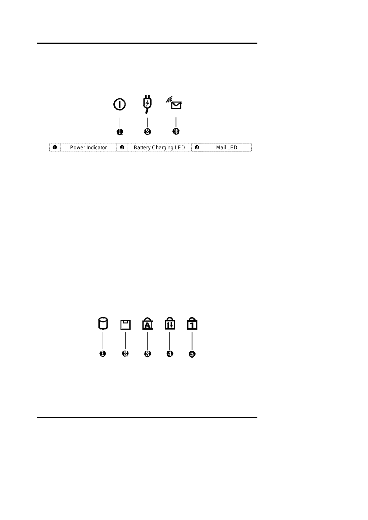
Power Status LED Indicator
Located just in front of the palmrest assembly, you will find three LEDs for the power and
battery charge status. These LEDs are positioned to be visible even if the LCD cover is
closed.
Power Indicator
n
Figure 1-4 Power Status LED Indicator
1. Power Indicator – lets you know if power to the s yste m is turn ed on a nd if system is in
Suspend-to-RAM mode. This LED is positioned so that you can see it on both sides
whether the LCD panel is opened or closed.
− Lights green when the system is powered on using the AC adapter or battery.
− Lights green blinking when in Suspend to RAM (or Suspend to Disk) if you
already created Save to Disk partition/file in HDD mode and critically low
battery power. We strongly recommend that users create the partition/file "Save
to Disk" as this will prevent your data from loss when power is critically low.
− Lights orange when the battery power is low.
2. Battery Charging LED – lights to indicate battery in charging status.
− Lights green to indicate the battery is charging.
− Lights off to indicate the battery is fully charged or no battery installed.
3. Mail LED – Lights green to indicate that a new mail is arrived.
Status LED Panel
The Status LED Panel keeps you informed of the notebook’s current operating status. Each
LED is marked with an icon to designate a system status.
Battery Charging LED
o
p
Mail LED
Figure 1-5 Status LED Panel Icons
1-8 FIC A360 Servic e Manual
Page 20
Outline of the A360
Icon Represents Indicates
n
o
p
q
r
IDE Drive
Access
Diskette Drive
Access
Caps Lock This LED will turn on when the Caps Lock key is activated.
Scroll Lock
Num Lock
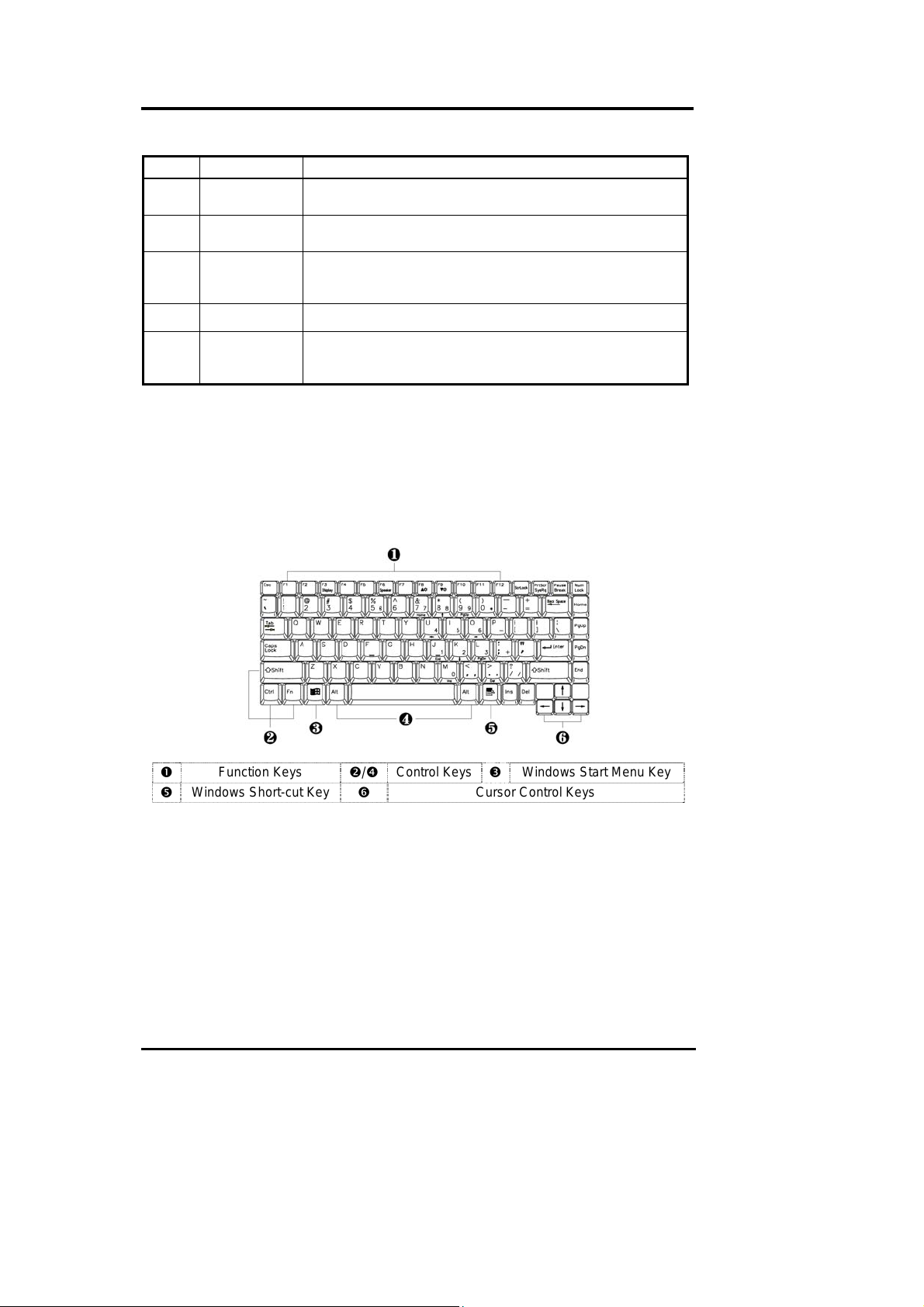
Keyboard Panel
− Standard QWERTY-key layout and full-sized 87/90 keys keyboard with Windows
hot-keys, embedded numeric keypad, hot keys, inverted “T” cursor arrow keys,
and separate page screen control keys.
− Wide extra space below the keyboard panel for your wrist or palm to sit-on
comfortably during typing. (The keypad F4, F5, F7 on the following keyboard
should no words print on it.)
This LED will turn on when the system is accessing the hard
disk drive (HDD) or CD-ROM / DVD-ROM / CD-RW.
This LED will turn on when the system is accessing the floppy
disk drive (FDD).
When activated, all alphabet keys typed in will be in upper
case or in capital letters.
This LED will turn on when the Scroll Lock key is activated.
This LED will turn on when the Num Lock key is activated.
When activated, the embedded numeric keypad (blue pri nt
numeric keys) will be enabled.
n
r
Function Keys
Windows Short-cut Key
Figure 1-6 Keyboard Layout
o/q
The notebook keyboard is a little bit different from a standard desktop keyboard. Aside
from the normal alphanumeric characters and the standard keyboard function keys, the
notebook keyboard includes an embedded numeric keypad, and special function keys that
activates by pressing the <Fn> key together with another key. These special function keys
or “hot-keys” allow you to control and adjust some of the functions of the notebook like
display controls, power saving features, and others.
(1) Function Keys — These function keys, o ut of
the notebook keyboard. These keys also work together with the
special functions. The following function-key combinations are pre-programmed:
FIC A360Service Manual 1-9
s
Control Keys
Windows Start Menu Key
p
Cursor Control Keys
<F1> through <F12>, are available on
<Fn> key to activate
Page 21
Outline of the A360
Hot Key Function Handler
Fn + F3 Toggle Display (LCD/CRT/Simul) BIOS Handler
Fn + F5 Display stretching BIOS Handler
Fn + F6 Speaker On/Off BIOS Handler
Fn + F8 Brightness Increase Controlled by PMU07
Fn + F9 Brightness Decrease Controlled by PMU07
Fn + F12
Fn + Power button System Suspend to disk BIOS Handler
(2) Control keys – <Ctrl>, <Alt>, <Fn>, and <Shift> keys are controls used in
conjunction with other keys to change their functions. To use control keys, press and
hold the control key while pressing another key. For example, “Press
means to hold down the
(3) Windows keys (Windows Start Menu Key) – Use this key to activate the Start
Menu of Windows.
(4) Shortcut/Application key – provides quick access to shortcut menus. (This key acts
like a right mouse button.)
(5) Cursor Control keys – Cursor control keys let you position the cursor on the screen
where you want. On the screen, the cursor is a blinking underline, block, or vertical
bar depending on the application.
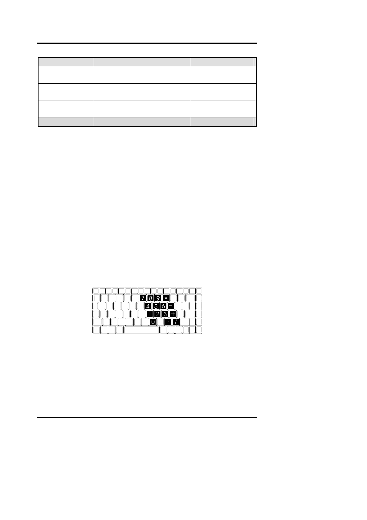
(6) Typewriter keys – Typewriter keys (also called alphanumeric keys) are used to enter
text and characters. Keys with blue print on them behave differently when combined
with control keys or the
(7) Numeric Keypad – Pr ess i ng
numeric keypad numbers and functions printed in blue on top of the keys. When you
press
<NumLock> again, the keys revert to their normal functions as typewriter keys.
<Ctrl> key and type the letter <C>.
<Fn> key.
<NumLock> on the keyboard activates the embedded
<Ctrl>+ <C>”
Figure 1-7 Embedded Numeric Keypad
Integrated Microphone
This allows you to instantly record voice annotations (normally saved as WAV files) and later
attached them to documents and presentation using the notebook integrated audio system and
application software. Since the notebook also supports full-duplex audio capabilities, you can
talk to the microphone and at the same time listen to others talk when connected to a
speakerphone modem, Internet live chat, or video conferencing.
1-10 FIC A360 Servic e Manual
Page 22
Outline of the A360
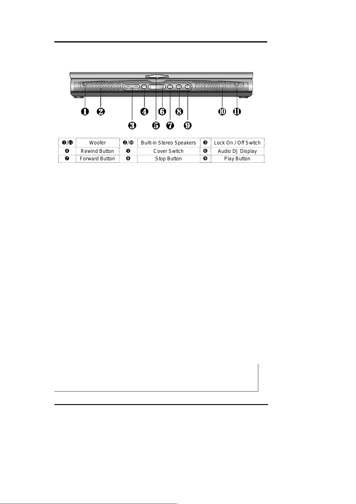
1.4.2 Front Side of the Notebook
n/
q
t
Woofer
These speakers produce heavy bass voice output for music listening.
Built-in Stereo Speakers
At the front left and right sides of the base unit are two built-in stereo mini speakers with
sound boxes. The speakers are controlled by the audio controller of the notebook and
activated by installing the audio driver. For adjusting the volume of the speakers, you can use
the volume control program under Microsoft OS or by adjusting the thumb-wheel volume
knob also found on the left side of the notebook.
Lock On / Off Switch
This Lock Switch executes two functions as to power on/off the Audio DJ CD player and to
lock or unlock the Audio DJ status. To power on or off the Audio DJ CD player, slide the
switch right aside. To lock or unlock the status of your Audio DJ, slide the switch left aside.
When your Audio DJ is in locking status while the music is playi n g, no matter what button is
pressed, the music still continues to play. The function of this switch is to prevent you from
touching any button accidentally.
Remind Button
Press the button for reverting to previous music. Press and hold this button to fast rewind the
audio CD.
Cover Switch
The Cover Switch is found inside the notebook assembly just underneath the latch opening
where you insert the LCD cover hook. Whenever the LCD cover is closed, it activates the
Suspend mode or switches the display to CRT if there is an external monitor connected.
Woofer
Rewind Button
Forward Button
Figure 1-8 Front Side of the Notebook
o/w
Built-in Stereo Speakers
r
u
Cover Switch
Stop Button
Lock On / Off Switch
p
Audio DJ Display
s
v
Play Button
L When Suspend-to-RAM mode is activated, make sure not to leave the system
for a long period when running at battery mode. The battery will continue to drain
some power even in Suspend mode. It is better to save all files and shutdown
the power instead or run Suspend-to-Disk mode.
FIC A360Service Manual 1-1 1
Page 23
Outline of the A360
Audio-DJ Display
The display shows the number of the music currently playing.
Forward Button
Press the button for playing the next music. Press and hold this button to fast forward the
audio CD
Stop Button
Press the button to stop the music.
Play Button
Press the button to play the music.
L The function of Audio DJ can be workable either in Windows system or operate it
without powering on th e computer. For execute this function, you should first
install the Easy Button driver. Please refer to Section 5 of Chapter 2 of user
manual for installation procedures. However, if your OS is Windows 98, you
should download and install the "Windows Media Player 7" from Microsoft's
Website to activate this function.
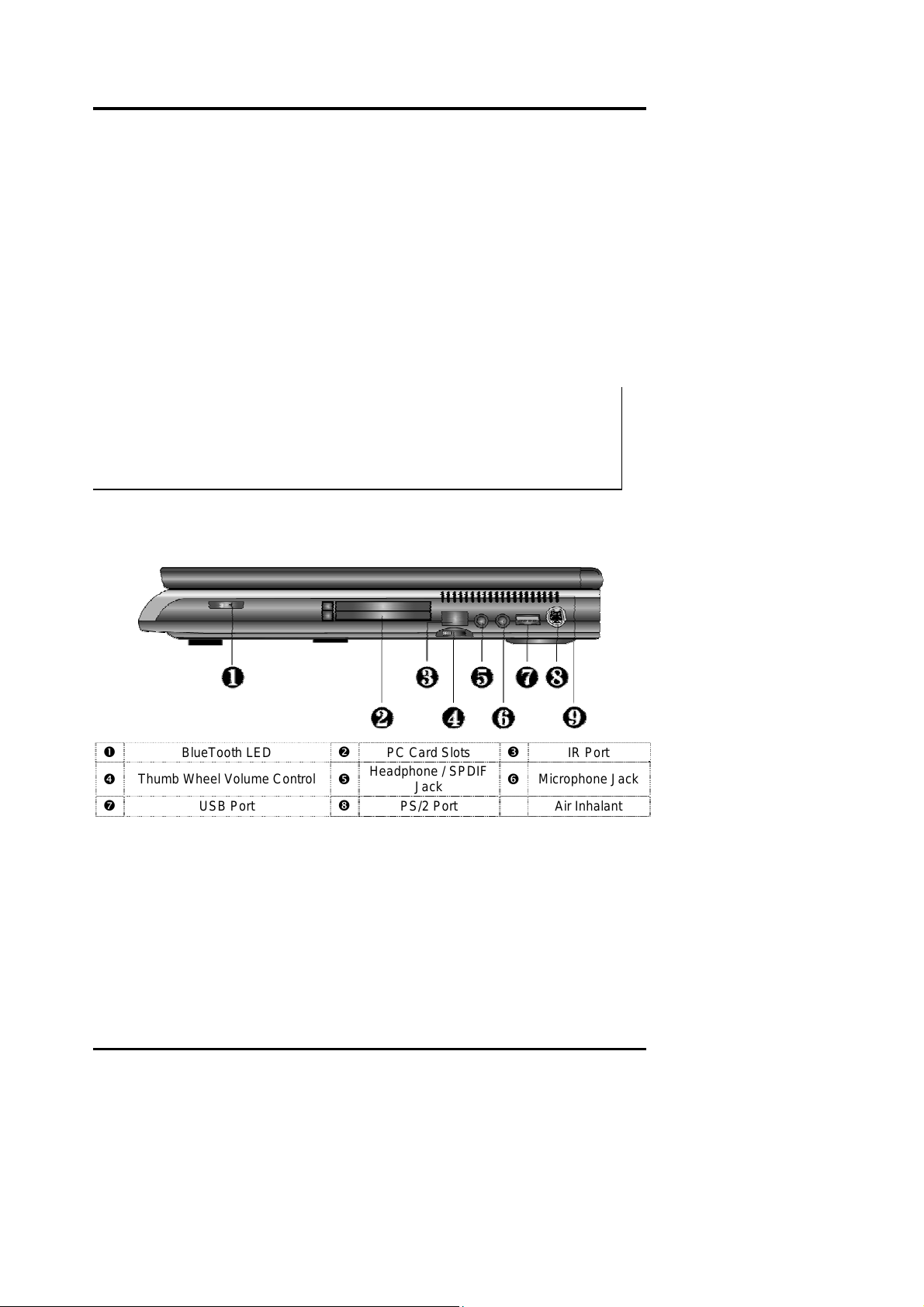
1.4.3 The Right Side of the Notebook
The right side of the notebook computer off ers the features shown in the following figure.
IR Port
n
q
t
BlueTooth LED
Thumb Wheel Volume Control
USB Port
o
r
u
PC Card Slots
Headphone / SPDIF
PS/2 Port
Jack
p
Microphone Jack
s
Air Inhalant
Figure 1-9 Right Side of the Notebook
BlueTooth LED
The LED is light when you activate with the Bluetooth function.
PCMCIA Slot Compartment
The PCMCIA slot compartment houses two card slots that support two PCMCIA Type II
cards at the same time or one Type III card. The notebook uses a CardBus PCMCIA
controller that supports 5V and 3V 32-bit CardBus and 16-bit PC cards. The PCMCIA slot
1-12 FIC A360 Servic e Manual
Page 24

Outline of the A360
compartment comes with vertical sliding doors so you can directly insert the PC card. If you
are using a Type III card, insert the Type III card into the top slot.
To remove the inserted PC card, slightly push the button found on the right side of the PC slot
to release the eject button. Then push it again to relea se the PC card. The u pper lef t butt o n
releases the card on the top slot while the lower right button releases the card on the bottom
slot. When the PC card has moved out a space out of the slot, hold the edges of the card and
slowly slide it out.
L For full functionality of PC cards, always ask for the latest driver from your
PCMCIA card dealer or download it from their Internet website.
L For network PC cards, you need first to stop the device under the PC Card
properties of Windows Control Panel. Otherwise, this may cause system hang or
system fatal error.
IR Port
Wireless data transfer of files be twee n your n otebook computer and an IR-equipped device or
notebook computer. You can also print to an IR-equipped printer without using cables. The
SIR mode provides up to 115.2Kbps of data transfer rate.
Thumb-Wheel Volume Control
The notebook includes a thumb-wheel volume knob to easily adjust the volume level of the
built-in speakers or the external earphone/headphone set.
Headphone Jack
This jack (1/8-inch mini-jack) allows you to connect an external headphone, earphone, or
powered speakers for personal listening.
L Turn the volume level down first before placing the earphone or headphone set
into your ear. Then ad just the volume according to y our li s tening level.
L If you get noise feedback on the external speaker, try to lower down the volume
knob on the speaker and adjust the volume using the notebook’s volume control
buttons or the software.
Microphone Jack
The microphone jack (1/8-inch mini-jack) allows you to connect an external microphone with
600-ohm dynamic in place of the built-in microphone of the notebook for monophonic sound
recording directly into your notebook computer. The external microphone provides lesser
recording noise compared to the built-in microphone of the notebook.
L Plugging in an external microphone disables the internal microphone.
USB (Universal Serial Bus) Ports
The USB (Universal Serial Bus) Port is a port with the symbol
you to connect multiple USB devices through daisy chaining or through a USB hub and use them
all simultaneously. The USB specification states it can support up to 127 USB devices running at
. This 4-pin slim port allows
FIC A360Service Manual 1-13
Page 25
Outline of the A360
up to 12Mbps. This notebook provides two USB ports.
L When you resume the system from suspend mode, the USB port may not
initialize properly. If in case the USB device does not work, unplug and plug the
USB device again. This is a known bug released by Intel and Microsoft
Windows.
PS/2 Port
Use the standard PS/2 port to connect an external PS/2-style mouse, PS/2-style keyboard, or
PS/2 style Numeric Keypad to the system. With a Y-cable adapter which user can purchase at
local electronic store, user can connect any combination of two of these devices at the same
time. For non-PS/2 keyboard, you need to use a keybo ard ada pter t h at converts the DIN-type
connector to PS/2 connector.
Air Inhalant
Inhale the air into your computer to keep it within operating temperature.
L Do not block the fan while the notebook is in use.
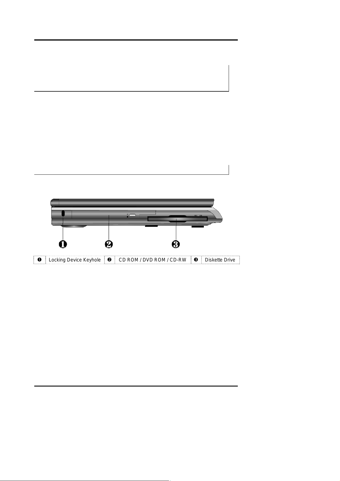
1.4.4 The Left Side of the Notebook
Locking Device Keyhole
n
Locking Device Keyhole
Lets you attach a Kensington security system or a compatible lock to secure your notebook
computer.
CD-ROM / DVD-ROM / CD-RW Drive
The notebook comes with a standard 24X+ speed ATAPI IDE CD-ROM drive that supports
all major CD formats like CD-R, Photo CD, and Video CD. The drive utilizes a pop-out tray
loading mechanism and supports bootable CD by setting the BIOS Setup program. Refer to
Chapter 2 of User Manual on how to install the CD-ROM driver. The notebook also comes
with the 8X+ speed DVD-ROM drive or 4X+ speed CD-RW driver options.
Floppy Diskette Drive (FDD)
The built-in 3.5 inch FDD allows you to use any standard double-sided high-density (DSHD)
1-14 FIC A360 Servic e Manual
Figure 1-10 Right Side of the Notebook
CD ROM / DVD ROM / CD-RW
o
Diskette Drive
p
Page 26
Outline of the A360
diskette for copying and transferring data files. In the BIOS Setup program of the notebook,
you also could disable the FDD option or set a password option when accessing the drive.
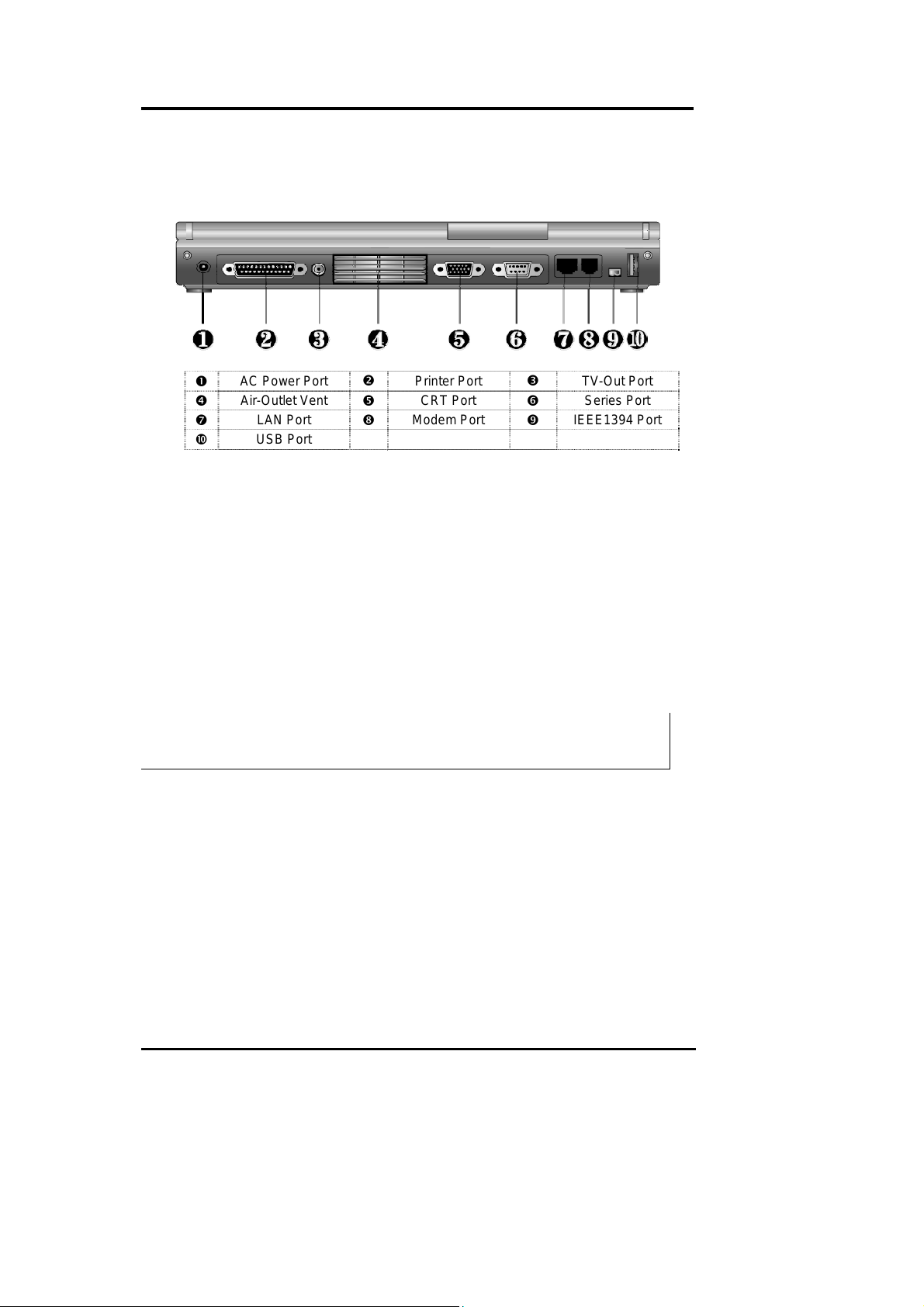
1.4.5 The Rear Side of the Notebook
AC Power Port
n
Air-Outlet Vent
q
t
w
AC Power Port
Lets you attach the notebook to the AC power source using the AC adapter that comes with
your system. Keep the system connected to AC power whenever possible to keep the battery
pack and internal CMOS battery charged. The Battery Charge LED will activate whenever
the battery is being recharged.
Printer Port (LPT1)
The printer port lets you connect a 25-pin parallel device such as printer, ZIP drive, or remote
data transfer cable. Many operating systems and software applications refer to this port as
LPT1. You can run t h e BI O S setup program to change the configuration of the parallel port to
Uni-directional, ECP or EPP mode.
LAN Port
USB Port
Figure 1-11 Rear Side of the Notebook
o
r
u
Printer Port
CRT Port
Modem Port
p
s
v
TV-Out Port
Series Port
IEEE1394 Port
L The default setting for the parallel port on your notebook computer is set to EPP
mode. Some parallel devices may not function with the default setting. You need
to run the BIOS Setup program to adjust the settings.
TV-Out Port Lets you connect to a RCA TV connector for presentation or VCD, DVD watching.
Air-Outlet Vent
Emits the heat out of your computer and keeps it within operating temperature.
VGA Port (CRT)
The VGA port lets you connect an external VGA (CRT) monitor to the notebook. You can
also run the LCD and the external CRT monitor display simultaneously; or switch it to CRT
only using the function hot-key (Fn+F3). When switch to CRT only, you can set the display
resolution up to 1280x1024 at 16M colors (32-bit true color).
FIC A360Service Manual 1-15
Page 27

Outline of the A360
Series Port (COM 1)
The 9-pin serial port provides a serial interface to which you can connect an RS-232C device
such as external serial mouse or modem. This port is commonly referred to as COM1.
L When connecting an external serial mouse, you m u st first power off the system
before connecting the external mouse. It can auto-detect the serial mouse
hardware and run both glide pad and serial mouse simultaneously.
L Whenever using an external mouse in place of the built-in glide pad, it is
recommended to switch the mouse driver to the default standard Microsoft
mouse driver.
LAN Port
If you purchase an internal 10Base-T/100Base-TX LAN module, it connects your computer to
other computers/networks through a local area network (LAN).
Modem Port
The modem port provides a reserve jack for installing an internal modem with RJ-11 jack.
The internal modem is a 56Kbps-fax/data PCI modem and supports the latest V.90 standard
and sort of a PCI add-in card reduced into a smaller compact f orm. T he i nter na l mo du le u ses
mini-PCI technology and is inserted into the mini-PCI socket found on the underside of the
notebook. It keeps you connected to the outside world through networks.
IEEE1394 Port
IEEE 1394 port is a high speed I/O port that can transfer high levels of data in real-time, such
as external hard disk, Digital Video Camera.
USB (Universal Serial Bus) Ports
The USB (Universal Serial Bus) Port is a port with the symbol
you to connect multiple USB devices through daisy chaining or through a USB hub and use them
all simultaneously. The USB specification states it can support up to 127 USB devices running at
up to 12Mbps. This notebook provides two USB ports.
. This 4-pin slim port allows
L When you resume the system from suspend mode, the USB port may not
initialize properly. If in case the USB device does not work, unplug and plug the
USB device again. This is a known bug released by Intel and Microsoft
Windows.
1-16 FIC A360 Servic e Manual
Page 28
Outline of the A360
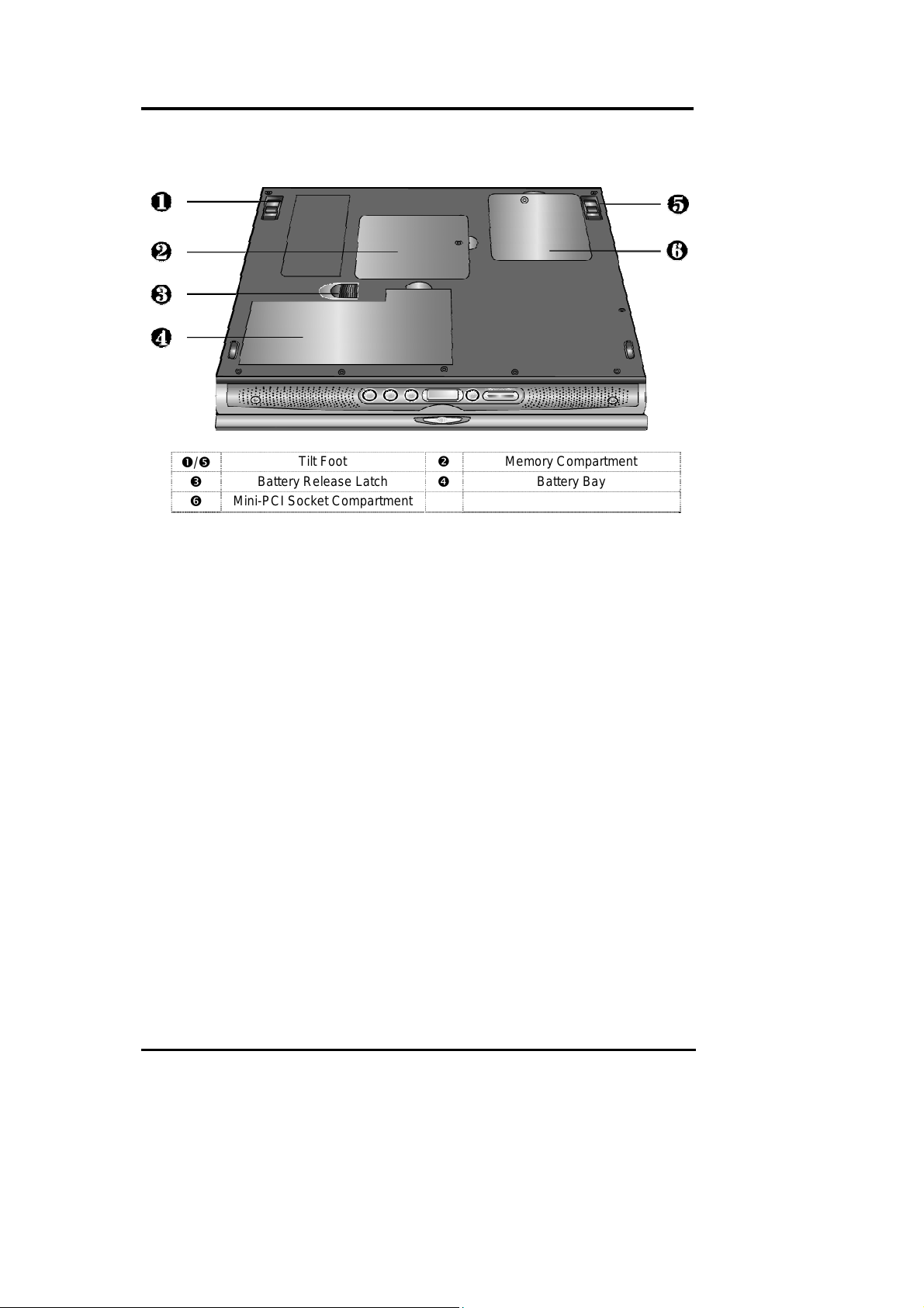
1.4.6 The Under Side of the Notebook
n/r
p
Mini-PCI Socket Compartment
s
Tilt Foot (Left and Right) Allow you to tilt the rear of the notebook upward to provide flexible keyboard angle for more
comfortable typing.
Memory Compartment
Found on the underside of the notebook is the memory compartment. Underneath the cover
are two 144-pin SODIMM memory slots for inserting and upgrading the system memory
using 64MB, 128MB, or 256MB SODIMM. The notebook uses PC-100/133 SDRAM
modules for faster memory access. You can upgrade the total memory up to 512MB. One is
inserted with a SDRAM configured by the factory. The other is empty for upgrade use. Refer
to Chapter 7 on how to upgrade the system memory.
Battery Release Latch
Also found on the underside of the notebook is the battery bay latch. To remove the battery
pack, you need to push this latch to the left end and at the same time pull the battery pack.
Battery Bay
The battery bay stores the Lithium-Ion (Li-Ion) or Nickel Metal-Hydride (NiMH) battery pack for
off-the-cord operation. The battery pack is instantly charge whenever you connect the AC adapter
to the notebook. It is very important to always have the battery installed on the notebook to have it
always charged and conditioned by the AC adapter.
Mini-PCI Socket Compartment This compartment provides the mini-PCI socket for inserting optional built-in Modem, LAN,
or Combo card. Refer to Chapter 2 of User Manual for installing the Modem module.
Tilt Foot
Battery Release Latch
Figure 1-12 Under Side of the Notebook
o
q
Memory Compartment
Batte ry Bay
FIC A360Service Manual 1-17
Page 29

Outline of the A360
1.5 Notebook Accessories and System Options
It is also important to understand the accessories that come along with the notebook and the
options for fully utilizing the capabilities of the computer. This section describes briefly what
these accessories and options are.
1.5.1 AC Adapter and Power Cord
The AC Adapter supplies external power to your computer and at the same time charges the
internal battery pack. The AC adapter has an auto-switching design that can connect to any
100VAC ~ 240VAC power outlets. Connect the adapter to the AC wall outlet using the power
cord. You just change the power cord if you are going to use your notebook in other countries
with different connector outlets. When you connect the AC adapter, it charges the battery
whether or not the notebook computer is powered on. There is an LED on the AC adapter to
indicate if DC power is already available.
1.5.2 Battery Pack
Aside from the AC adapter, your computer can also be powered through the removable
battery pack. The battery pack uses rechargeable Nickel Metal-Hydride (NiMH) or LithiumIon (Li-Ion) battery cells that can run for 2 to 2.5 hours when fully charged and power
management enabled. Recharging the battery takes around 2.5 to 3 hours when the computer
is off.
You should always leave the battery inside your computer even when using the AC adapter as
it also acts as back-up power supply in case power from the AC adapter is cut off. It is also
very important to have the battery pack always charged to prevent battery cell degradation. If
the AC adapter is not connected or not available, and the notebook is not going to be used for
some period, it is advisable to remove the battery pack from the notebook to prevent any
current leak.
1.5.3 Internal Modem Module
The notebook allows you to insert a proprietary internal 56Kbps-modem card to the notebook
found on the underside of the notebook. The internal modem card supports only fax and data
communication and is V.90-compliant. You connect the telephone line to the RJ -11 j ac k
found on the rear side of the notebook.
1.5.4 Internal Ethernet LAN Module
This notebook comes with an optional 10Base-T/100Base-TX LAN module that supports data
transfer rates at 10Mbps and can be up to 100Mbps.
1.5.5 DVD-ROM Drive
Other than the internal CD-ROM drive, the notebook also provides optional factory built-in
DVD-ROM drive. DVD-ROM drives are also backward compatible with CD-ROM, so you
can also use any audio CDs, video CDs, photo CDs, and CD-R. Using a software MPEG2/DVD program, the notebook can playback any commercial DVD movie titles.
1.5.6 CD-RW Drive
This device pack can write data to CD-R or CD-RW CD for you to backup the data.
1-18 FIC A360 Servic e Manual
Page 30

Outline of the A360
1.5.7 Audio-DJ
This notebook comes with optional built-in Audio DJ panel. It can play your Audio CD like
the CD player without powering on the whole computer.
1.5.8 Blue T oot h Module
This notebook is ready for Bluetooth technology. This is a wireless connection standard in a
short-range radio technology. It aims at simplifying communication between each device with
bluetooth module. Bluetooth is in essence a “personal-area network” technology for
connecting computers to peripherals and mobile ph ones.
1.6 System BIOS SETUP Program
The notebook uses the Phoenix BIOS (Basic Input-Output System) Setup program that allows
you to set several system configurations in changing the way the system performs. This
includes your system time and date, disk drive configuration, I/O device controls, boot drive
sequence, and power management settings. The information is then stored in the CMOS RAM
chip and will remain permanent unless you cha nge it again. The notebook also uses EPROM
Flash BIOS that allows you to update the system BIOS by simply overwriting it using the
Phoenix Flash programming utility.
Before boot-up, the system will read the BIOS settings and compare them to the equipment
check conducted during the POST (Power-On Self-Test). As the POST (Power-On Self Test)
executes during the boot up process or if an error occurs, an error message will be displayed
on the screen, the screen will display the following message: ”Press <F2> to Enter SETUP”.
You will then be prompted to run the BIOS Setup Program by pressing the <F2> key to run
the BIOS Setup program.
The BIOS Setup program is organized into five menus which you can select using the Å and
Æ keys. To move from one option to another, you use the up and down arrow keys while
using the <F5> and <F6>, or <+>and <-> keys to change the settings. On the right hand side
of the screen are some brief help descriptions of each item you want to change.
On the BIOS Setup program, you will find the following parts on the screen:
• Menu Bar - found on the top li ne of the screen. Each of the five items has a separate
menu screen.
• Parameters - found on the left side of the screen. This ar ea l ists the para m e ters an d
their current settings.
• Item Specific Help - found on the right side of the screen. This area describes each
parameter and its available settings.
• Key Status Bar- the bottom part of the screen. These lines display the keys available
to move the cursor, select a particular function and so forth.
To exit the BIOS Setup program, simply press the <Esc> key and select from the Exit menu
whether you want to Save changes and exit; Discard Changes and exit.
The following table lists the keys on how to edit and move around the setup menus inside.
FIC A360Service Manual 1-19
Page 31

Outline of the A360
KEY WHAT IT DOES
<F1> Shows on-line help on key functions.
↑ ↓
- / + Modifies the current parameter settings.
<F9> Load default configuration.
Esc
ÅÆ
<Enter>
<F10> Save changes and exit.
Moves the cursor between the displayed parameters.
Exits the current menu and returns to the main menu or go directly to
the Exit menu.
Changes between displayed menus.
For some parameter settings, select and moves the cursor between
the sub-menu. Also moves the cursor to the next line or selection.
L Some information here may not be available or different from other date code
versions of the notebook BIOS. Always check for the latest BIOS update from
the FIC Internet homepage. ftp://pcg.fic.com.tw/NBTECH
1.6.1 Using the Main Menu
The BIOS Setup Main Menu contains the settings for system time and date, and disk drives as
well as CPU and system memory information.
PhoenixBIOS Setup Utility
Main Advanced Security Boot Exit
Item Specific Help
System Time: [12:00:00]
System Date: [01/01/2001] <Tab>, <Shift-Tab>, or
Language: [English (US)] <Enter> selects field
Diskette A: [1.44/1.25 MB 3½”]
Internal HDD [20004MB]
4
Internal DVD/CD-ROM Installed
Boot Display Device: [Both]
System Memory 640 KB
Extended Memory 262143 KB
CPU Type Pentium® III
CPU Speed 1000 MHz
BIOS Version 1.0A-0003-3330
F1 Help
Esc Exit
Select Item -/+ Change Values F9 Setup Defaults
K
Select Menu Enter Select 4Sub-Menu F10 Save and Exit
st
Figure 1-13 BIOS Setup Main Menu
1-20 FIC A360 Servic e Manual
Page 32

Outline of the A360
System Time: [12:00:00] <Tab>, <Shift-Tab>, or <Enter> selects field.
System Date: [01/01/2001] <Tab>, <Shift-Tab>, or <Enter> selects field.
Language:
Diskette A:
Internal HDD [10056MB]
Internal DVD/CD-ROM Installed / Not installed (BIOS auto detect, for information only)
Boot Display Device:
System Memory 640 KB (BIOS auto detect, for information only)
Extended Memory 262143 KB (BIOS auto detect, for information only)
CPU Type Pentium (R) III (BIOS auto detect, for information only)
CPU Speed 900MHz (BIOS auto detect, for information only)
BIOS Version 1.0A-0221-0713 (BIOS auto detect, for information only)
[English (US)]
[Disabled] /
[1.44/1.25MB 3½”]
[Both] / [CRT] / [LCD]
System Time –Allows you to change the system time using the
hour:minute:second format of the computer. Enter the current time for reach field
and use the <Tab>, <Shift>+<Tab>, or <Enter> key to move from one field or back
to another. You can also change the system time from your operating system.
System Date – This field lets you set the system date using the month/date/year
format. Enter the current time for reach field and use the <Tab>, <Shift>+<Tab>, or
<Enter> key to move from one field or back to another. You can also change the
system time from your operating system.
Language – This field allows you to select the display language for the BIOS by
the <Tab>, <Shift>+<Tab>, or <Enter> key to move from one field or back to
another..
Diskette Drive A – This field allows you to enable or disable the built-in 1.44
3½
” Diskette by pressing the <Enter> key.
Internal HDD – This field displays various param eter s for the hard d isk drive. If
type [Auto] is selected, the system automatically sets these parameters. If type
[User] is selected, Cylinders, Heads and Sectors can be edited.
Internal DVD/CD-ROM –This field is for information only as the BIOS
automatically detects the internal CD-ROM or DVD-ROM Drive.
Boot Display Device – This field allows you to set the output boot display to
the LCD, CRT, or Both.
System Memory, Extended Memory, CPU Type, CPU Speed and
BIOS Version – These fields are for information only as the BIOS automatically
detects related values during Power-On Self-Test (POST).
Select floppy type.
Choose the display device.
FIC A360Service Manual 1-21
Page 33

U
Outline of the A360
Internal HDD Sub-Menu
PhoenixBIOS Setup Utility
Main
Internal HDD [10056MB] Item Specific Help
Type: [Auto]
Cylinders: [16383] Parameters of hard-disk
Heads: [16] Drive installed at this
Sectors: [63] Connection.
Maximum Capacity: 10056MB Auto = autotypes
Hard-disk drive
Multi-Sector Transfers: [16 Sectors] Installed here
LBA Mode Control: [Enabled] 1-39 = you select
32 Bit I/O: [Disabled] pre-determined type of
Transfer Mode: [FPIO 4 / DMA 2] hard-disk drive
SMART Monitoring: Enabled Install here.
Ultra DMA Mode: [Mode 4] CD-ROM = a CD-ROM drive
is installed here.
ATAPI Removable =
Removable disk drive is
installed here
F1 Help
Esc Exit
Select Item −/+ Change Values F9 Setup Defaults
K
Select Menu Enter Select Sub-Menu F10 Save and Exit
ÅÆ
Figure 1-14 Internal HDD/CD-ROM Sub-Menu
Type: [None] / [CD-ROM] / [User]
Cylinders: [16383] (BIO S aut o detect, for information only)
Heads: [16] (BIOS auto detect, for information only)
Sectors: [ 63] (BIOS auto detect, for information only)
Maximum Capacity: 10056MB (BIOS auto detect, for informati on only)
Multi-Sector
Transfers:
LBA Mode Control: [Disabled] / [Enabled]
32 Bit I/O:
Transfer Mode:
SMART Monitoring [Disabled] / [Enabled] HDD provides the function of SMART Monitoring
Ultra DMA Mode: [Mode 1] / [Mode 2] (BIOS auto detect, for information only)
/ [Auto]
[Disabled] / [2 Sectors] /
[4 Sectors] / [8 Sectors] /
[16 Sectors]
[Disabled] / [Enabled]
[Standard] / [Fast PIO 1] /
[Fast PIO 2] / [Fast PIO 3] /
[Fast PIO 4] / [FPIO 3 /
DMA1] / [FPIO 4 / DMA2]
Select the drive type corresponding to the fixed
disk installed in your system. If type USER is
selected, Cylinders, Heads & Sectors edited
directly.
Determine the number of sectors per block for
multiple sector transfers.
Enabling LBA causes Logical Block Addressing
to be used in place of Cylinders, Heads &
Sectors
This setting enables or disables 32 bit IDE data
transfers
Select the method for moving data to/from the
drive. Autotype the drive to select the optimum
transfer mode
ser = you enter
1-22 FIC A360 Servic e Manual
Page 34

Outline of the A360
1.6.2 Using the Advanced Menu
The Advanced Menu allows you to configure the OS and I/O device settings.
PhoenixBIOS Setup Utility
Main Advanced Security Boot Exit
Item Specific Help
PS/2 Mouse [Enabled]
LCD Panel View Expansion- [Enabled]
Silent Boot: [Enabled] ‘Disabled’ prevents any
Frame Buffer Size: [8 Mb] installed PS/2 mouse
from functioning, but
I/O Device Configuration frees up IRQ 12.
4
‘Enabled’ allows the
operating system to
determine whrther to
Enable or disable the
mouse.
F1 Help
Esc Exit
PS/2 Mouse
LCD Panel View
Expansion-
Silent Boot:
Frame Buffer Size [None] / [8 Mb] /
4I/O Device Configuration
PS/2 Mouse – [Disabled] prevents any installed PS/2 mouse from functioning,
but frees up IRQ12. [Both] allows both internal and external PS/2 mouse to be
active. [Auto] will only allow the external PS/2 mouse to be active if it is detected.
Select Item -/+ Change Values F9 Setup Defaults
K
Select Menu Enter Select Sub-Menu F10 Save and Exit
st
Figure 1-15 BIOS Setup Advanced Menu
[Disabled] / [Enabled]
[DISABLED] / [ENABLED]
[Enabled] / [Disabled] /
[Black]
[16 Mb] / [32 Mb]
Submenu Peripheral Configuration
[Disabled] prevents any installed PS/2
mouse from functioning, but frees up
IRQ12. [Enabled] allows the operating
system to determine whether to enable
or disable the mouse.
[Disabled] Reduces the panel view in
some video mode. [Enabled] Expands
the panel view, but it may adversely
affect the graphic/text quality
Select boot screen using options:
[Enabled] – Logo screen on boot
[Disabled] – POST screen on boot
[Black] – Black screen on boot
Sharing VGA memory size from
SDRAM. Recommend you setting the
default value to 8MB. If you want to
play DVD with Power DVD, please set
the size of VGA frame buffer size to
16MB or 32MB and enable Hardware
accelerator function under Power DVD.
FIC A360Service Manual 1-23
Page 35

C
Outline of the A360
LCD Panel View Expansion-
Silent Boot – Select boot screen during POST.
Frame Buffer Size – Allows you to select sharing VGA memory size from
SDRAM. If you want to play DVD with Power DVD, please set the size of VGA
frame buffer size to 16MB or 32MB and enable Hardware accelerator function
under Power DVD.
I/O Device Configuration – Lets you configure input/output device such
as Serial Port, Parallel Port, and Floppy disk controller.
PhoenixBIOS Setup Utility
Advanced
I/O Device Configuration Item Specific Help
Serial port A: [Enabled] using options:
Base I/O address [3F8 IRQ4]
Infrared port: [Enabled] [Disabled]
Mode: [IrDA] No configuration
Base I/O address [2F8 IRQ3]
Parallel port: [Enabled] [Enabled]
Mode: [EPP] User configuration
Base I/O address [378]
Floppy disk controller: [Enabled] [Auto]
BIOS or OS chooses
configuration
F1 Help
Esc Exit
Select Item -/+ Change Values F9 Setup Defaults
K
Select Menu Enter Select Sub-Menu F10 Save and Exit
st
Figure 1-16 I/O Device Configuration Sub-Menu
Serial port A
Base I/O address
Infrared port
Mode
Base I/O address
[Disabled] / [Auto] /
[Enabled]
[3F8 IRQ4] / [2F8 IRQ3] /
[3E8 IRQ4] / [2E8 IRQ3]
[Disabled] / [Auto] /
[Enabled]
[IrDA]
[3F8 IRQ4] / [2F8 IRQ3] /
[3E8 IRQ4] / [2E8 IRQ3]
Configure serial port A using options:
Disabled - No configuration,
Enabled - User configuration,
Auto - BIOS or OS configuration.
Set the base I/O address for serial port A.
Configure Infrared port using options:
Disabled - No configuration,
Enabled - User configuration,
Auto - BIOS or OS configuration.
Set the mode for Infrared port
Set the base I/O address for Infrared port.
onfigure serial port
Gelöscht: <#>Local BUS IDE
adapter – Enable the integrated local bus
IDE adapter.
Formatiert
1-24 FIC A360 Servic e Manual
Page 36

Outline of the A360
Parallel port
Mode
Base I/O address
Floppy disk
controller
[Disabled] / [Auto] /
[Enabled]
[ECP] / [EPP] /
[Uni-directional]
[378] / [278] / [178]
[Disabled] / [Enabled] Configure the floppy disk controller using
Configure parallel port using options:
Disabled - No configuration,
Enabled - User configuration,
Auto - BIOS or OS configuration.
Set the mode for the parallel port using
options: Uni-directional, EPP, and ECP
Select the base I/O address for the parallel
port when port is Enabled.
options:
Disabled - No configuration,
Enabled - User configuration
L If you disable a device in BIOS Setup, you cannot enable or assign it using the
Windows (98 or 2000) Device Manager. The device is not listed in the Windows
device list. You need to select any setting other than “Disable” in Setup.
Serial Port A – You can press <Enter> to select Enabled, Disabled, or Auto
option for enabled or disabled this port, or automatically sensed the address
assignment by BIOS or OS. When you set the configured parallel port to Enabled
rather than Auto, you should also set the parameter of Base I/O address for this port.
Infrared Port – You can press <Enter> to select Enabled, Disabled, or Auto
option for enabled or disabled this port, or automatically sensed the address
assignment by BIOS or OS. When you set the configured parallel port to Enabled
rather than Auto, you should also set the parameter of Base I/O address for this port.
Parallel Port – Allows you to press <Enter> to select the Enabled, Disabled,
or Auto option for enabled or disabled this port, or automatically sensed the address
assignment by BIOS or OS.
Mode – Allows you to press <Enter> to select a parallel mode as Uni-directional,
EPP, or ECP when the parallel port is configured. When you set the configured
parallel port to Enabled rather than Auto, you should also set the parameter of Base
I/O address for this port.
Floppy Disk Controller –Allows you to press <Enter> to select the
Enabled or Disabled option for configured or not configured the floppy disk
controller.
FIC A360Service Manual 1-25
Page 37

S
Outline of the A360
1.6.3 Using the Security Menu
The Security menu allows you to set the system password as well as disk-protection security.
PhoenixBIOS Setup Utility
Main Advanced Security Boot Exit
Item Specific Help
Set Supervisor Password [Enter]
Set User Password [Enter] controls access to the
setup utility.
Password on boot: [Disabled]
Fixed disk boot sector: [Normal]
Diskette access: [Supervisor]
F1 Help
Esc Exit
Select Item -/+ Change Values F9 Setup Defaults
K
Select Menu Enter Select Sub-Menu F10 Save and Exit
st
Figure 1-17 BIOS Setup Security Menu
Set Supervisor Password Press Enter
Set User Password Press Enter
Password on boot
Fixed disk boot sector
Diskette access
[Disabled] / [Enabled]
[Normal] / [Write
protect]
[User] / [Supervisor]
Set Supervisor Password – Specifies if the system prompts you to enter a
password when entering Setup.
Set User Password – Specifies if the system prompts you to enter a password
when accessing the system. The Set User Password function will be enabled once a
Supervisor password is set. Enter a new password with up to eight alphanumeric
characters, and then enter this same new password again for confirmation.
Password on boot – Enables password check when booting.
Fixed disk boot sector – [Write Protect] enables write protect boot sector
on hard disk to prevent against viruses. [Normal] disables this write protect
function.
Diskette access – Controls access to diskette drive.
upervisor Password
Supervisor Password controls access to
the setup utility.
User Password controls access to the
system.
Enabled password entry on boot
Write protects boot sector on hard disk,
to protect against viruses.
Control access to diskette drives.
1-26 FIC A360 Servic e Manual
Page 38

Outline of the A360
1.6.4 Using the Boot Menu
The Boot menu lets you decide the boot order of booting devices including:
PhoenixBIOS Setup Utility
Main Advanced Security Boot Exit
Item Specific Help
+ Removable Devices
+ Hard Drive Use <K> or <> to
ATAPI CD-ROM Drive select a device, then
press <+> or <-> to
move the device up or
down.
<Enter> expends or
Collapses device.
F1 Help
Esc Exit
Select Item -/+ Change Values F9 Setup Defaults
K
Select Menu Enter Select Sub-Menu F10 Save and Exit
st
Figure 1-18 BIOS Setup Boot Menu
Removable Devices – put this option on top if you want to boot from a
bootable floppy diskette (Drive A:\).
Hard Drive – put this option on top if you want to boot from a bootable hard
disk drive (Drive C:\)
ATAPI CD-ROM Drive – put this option on top if you want to boot from a
bootable CD-ROM like Windows NT /2000 (Drive D:\).
Network Boot – put this option on top if you want to boot from LAN network
<Ctrl+Enter> expends
all.
FIC A360Service Manual 1-27
Page 39

E
Outline of the A360
1.6.5 How to Exit the Setup Program
There are three choices to escape from the Setup program.
PhoenixBIOS Setup Utility
Main Advanced Security Boot Exit
Item Specific Help
Exit Saving Changes
Exit Discarding Changes save your changes to
Load Setup Defaults CMOS.
Discard Changes
Save Changes
Battery Refresh
F1 Help
Esc Exit
Select Item -/+ Change Values F9 Setup Defaults
K
Select Menu Enter Select Sub-Menu F10 Save and Exit
st
Figure 1-19 BIOS Setup Exit Menu
Exit Saving Changes – Exits System Setup and saves your changes to
CMOS.
Exit Discard Changes – Exits Setup utility without saving Setup data to
CMOS.
Load Setup Defaults – Loads the default settings for all items in Setup.
Discard Changes – Reverts to previously selected settings.
Save Changes – Saves Setup data to CMOS.
Battery Refresh – Reactivate the battery.
xit System Setup and
1-28 FIC A360 Servic e Manual
Page 40

Chapter
Installation and Upgrade
2
2.1 Overview
This chapter provides guidelines on installing the device drivers for the built-in features of the
A360. Most of the driver installation procedures mentioned here are only for Windows 98 /
Me and Windows 2000. This chapter also includes procedures on how to upgrade major
internal system components like CPU, memory, hard disk, and feature card modules.
2.2 Notebook Drivers and Utilities
The notebook requires several device drivers that you need to install and setup before you can
fully operate the notebook. These are:
• Phoenix PHDISK Suspend-to-Disk Utility – DOS
• S3 Savage4 (Integrated in Twister) VGA Driver – Windows 98 / Me / 2000
• VIA PCI audio (Integrated in VT82C686B) Driver – Windows 98 / Me / 2000
• Synaptics Touch Pad Driver – Windows 98 / Me / 2000
• O2Micro OZ6933 PCMCIA Driver – Windows 98
• VIA Twister chipset Driver – Windows 98 / Me / 2000
• Easy Button Driver – Windows 98 / Me / 2000
• Easy Mail Driver – Windows 98 / Me / 2000
The notebook also comes with other option devices that requires driver installation:
• Askey 1456VQL19R-4 Data Fax Modem – Windows 98 / Me / 2000
• Ambit Intel 82562EH LAN – Windows 98 / Me / 2000
• Askey Combo Modem / LAN – Windows 98 / Me / 2000
L Visit FIC Support website ftp://pcg.fic.com.tw/NBTECH/ for the latest driver
updates.
2.2.1 R unning the PHDISK STD Utility
The PHDISK utility (version: 4 .32) of the notebook allows you to create a suspend-to-disk
(STD) file or partition that is used to save the opened files when you activate STD mode and
power off the computer. If you want to make use of the STD feature under Windows 98, you
need first to run the PHDISK utility.
L Since Windows Me, Windows 2000, or above version would be enabled
Hibernate Mode in place of suspend-to-disk (STD) Mode, it’s not necessarily to
run the PHDISK utility.
Running the PHDISK STD Utility
Load the notebook driver CD, look for the PHDISK program file, and run PHDISK under
Safe mode command prompt only in windows system. When you execute “PHDisk.exe”
first time, the program will ask you to choose one action from (1,2,3,4). Action 1 is “Create
partition”. Action 2 is “Create File”. Action 3 is “Reboot”. Action 4 is “Exit”. You can use
either of the following two options for executing PHDISK utility:
FIC A360 Serv i c e M anual 2-1
Page 41

Installation and Upgrade
1. PHDISK /Create /Partition - you can choose to run Suspend-to-Disk and save your
work into an allocated fixed disk partition. This option should be done before
partitioning and formatting your hard disk. The advantage of this option is that it is
more secure since the files are saved in a separate partition and has no risk of being
deleted. The disadvantage of this is that you need to allocate enough disk partition for
future memory upgrade. The STD partition should always be larger than the system
memory RAM.
2. PHDISK /Create /File - you can also choose to run Suspend-to-Disk and save your
work into a STD file. You do not need to allocate an extra disk partition when running
this option. The advantage of this is that you do not need to allocate or waste extra disk
partition. The disadvantage of this option is that it is less secure since there is risk of
deleting the STD file although the file is hidden.
It’s better to choose action 2 to create the SAVE2DSK.BIN file. The program will ask you to
input the size of this file. You just only input the value according to the suggestion. After
executing “PHDisk.exe”, you will get some information about the SAVE2DSK.BIN file
created by PHDISK program. The size of this file will depend on the installed RAM memory
of your computer. This file also is hidden and has read-only attributes.
After doing so or executing it next time, the program will ask you to choose one action from
(1,2,3,4). Action 1 is “Create File”. Action 2 is “Delete File”. Action 3 is “Reboot”. Action 4
is “Exit”. Choose action 1 to create another SAVE2DSK.BIN file or action 2 to delete it.
After PHDISK has completed the STD partition, you will be prompted to reboot the system.
L Whenever you upgrade the memory, you need to delete the existing STD file and
create a new one according to the new memory size. Run PHDISK and choose
action 2 to delete existing STD file.
2.2.2 Installing Windows 98 / Me / 2000 from CD / D VD ROM
This section provides Windows 98 / Me / 2000 installation guide from the CD-ROM or DVDROM device.
Installing Windows 98 / Me from CD-ROM / DVD-ROM
The easiest way to install Windows 98 / Me is to boot from Windows 98 start-up disk. With
Windows 98 / Me start-up disk, you don't need to install CD-ROM driver since the start-up
disk can support virtually all CD-ROM device. Insert Windows 98 / Me Installation CD into
CD-ROM drive and run "setup.exe".
If you don't have Windows 98 / Me start-up disk, you need to install CD-ROM /DVD-ROM
driver under DOS. Then, insert Windows 98 / Me Installation CD into CD-ROM drive and
run "setup.exe".
Installing Windows 2000 from CD-ROM / DVD-ROM
To install Windows 2000 directly from your CD-ROM, insert the Windows 2000 installation
CD into CD-ROM drive with following the instructions on the screen to finish the
installation. You could go to Boot menu of BIOS setup menu to confirm the priority of boot
device. Use arrow key to select "ATAPI CD-ROM Drive", and then use "+" or "-" to move it
to the top. Go to Exit menu and select “Exit Saving Changes”.
2-2 FIC A360 S e r v i c e Manual
Page 42

Installation and Upgrade
2.2.3 Installing the VGA Device Driv er
Your notebook computer uses the high-performance S3 Savage4 VGA controller, which is an
AGP 4x video local bus, 2D/3D Graphic Engine. Following is the procedure for installing the
VGA Driver for Windows 98, Windows Me and Windows 2000:
Installing VGA Driver for Windows 98
1. Boot Windows 98 from your hard disk and insert the disc containing the VGA driver for
Windows 98.
2. Click the Start button, then click Settings, and Control Panel. Double click System and
click Device Manager tab. Under Display Adapters, you'll see Standard PCI Graphics
Adapter (VGA). Select it and double click it.
3. Choose Driver button and then click Update Driver, Next, and Next again to search for
the driver.
4. Tick Specify a location and click Browse button. Then, navigate to
"\Drivers\Win98\VGA" and click Next.
5. Click Next to accept the updated driver for S3 Graphics Inc Twister driver.
6. Click Next to continue with VGA driver installation.
7. Click Finish to complete installation.
8. Restart Computer to finish setting up VGA.
Installing VGA Driver for Windows Me
1. Boot Windows Me from your hard disk and insert the disc containing the VGA driver for
Windows Me.
2. Click the Start button, then click Settings, and Control Panel. Double click System and
click Device Manager tab. Under Display Adapters, you'll see Standard PCI Graphics
Adapter (VGA). Select it and double click it.
3. Choose Driver button and then click Update Driver, Next, and Next again to search for
the driver.
4. Select "Specify the location of the driver" and click Next to continue.
5. Tick on "Specify a location box". Then, click Next and Browse buttons and navigate to
the VGA driver location as "\Drivers\ WinMe\VGA". Click OK and Next to begin
searching the driver.
6. The Update Device Driver Wizard will found S3 Graphics Inc. Twister. Click Next to
continue installing the driver.
7. Click Finish button to finish installing VGA driver and Yes to restart the computer.
Installing VGA Driver for Windows 2000
1. Click the Start button, then point to Settings, and click Control Panel.
2. Double-click on the System icon, Hardware, and then click on the Device Manager
folder tab.
3. Under the Other Devices line, you will find the Video Controller (VGA compatible),
and then Scan for Hardware Changes buttons to appear the New Hardware Found
Message Box.
4. In the Found New Hardware Wizard message box which shows searching Video
Controller (VGA compatible) driver. Click Next to proceed the further step.
5. Select "Search for a suitable driver for my device", and click Next.
6. Tick on "Specify a location box", then, click Next and Browse buttons, and then
navigate to the VGA driver location as "\Drivers\ Win2K\VGA".
7. Click OK and Next to begin searching the driver. The Add New Hardware will found S3
Graphics Inc. Twister.
FIC A360 Serv i c e M anual 2-3
Page 43

Installation and Upgrade
8. Click Next to continue installing the driver.
9. Click Finish button to finish installing VGA driver and Click Yes to restart the computer.
2.2.4 Installing the A udio Device Driver
Your notebook computer uses AD1886 AC97 Codec 2.1 Audio controller.
Installing Audio Driver for Windows 98
1. Boot Windows 98 from your hard disk and insert the disc containing the Audio driver for
Windows 98.
2. Click Start, Settings, and Control Panel. Double click System and click Device
Manager tab. Under Other Devices, you'll see PCI Multimedia Audio Device.
3. Click Refresh button. The Add New Hardware Wizard will detect PCI Multimedia
Audio Device.
4. Click Next to search for the driver. Click Next to continue.
5. Tick Specify a location and click Browse button. Then, navigate to
"\Drivers\Win98\Audio" and click Next.
6. Click Next to accept the updated driver for SoundMAX Integrated Digital Audio
driver.
7. Click Finish to complete installation. Restart Computer to finish setting up Audio.
Installing Audio Driver for Windows Me
1. Boot Windows Me from your hard disk and insert the disc containing the Audio driver for
Windows Me.
2. Click Start, Settings, and Control Panel. Double click System and click Device
Manager tab. Under Other Devices, you'll see PCI Multimedia Audio Device.
3. Click Refresh button. The Add New Hardware Wizard will detect PCI Multimedia
Audio Device. Click Next to search for the driver.
4. Select "Specify the location of the driver" and click Next to continue.
5. Tick on "Specify a location box", then click Next and Browse buttons and navigate to
the Audio driver location as "\Drivers\WinMe\ Audio".
6. Click OK and Next to begin searching the driver. The Update Device Driver Wizard
will found SoundMAX Integrated Digital Audio. Click Next to continue installing the
driver.
7. Click Finish button to finish installing Audio driver and Yes to restart the computer.
Installing Audio Driver for Windows 2000
1. Click the Start button, then point to Settings, and click Control Panel.
2. Double-click on the System icon, Hardware and then click on the Device Manager
folder tab.
3. Under the Other Devices line, you will find the Multimedia Audio Controller, and then
Scan for hardware changes buttons to appear the New Hardware Found Message Box.
4. In the Found New Hardware Wizard message box which shows searching Multimedia
Audio Controller driver. Click Next to proceed to the next step.
5. Select "Search for a suitable driver for my device", and click Next.
6. Tick on "Specify a location box", then click Next and Browse buttons, and navigate to
the Audio driver location as "\Drivers\ Win2K\Audio".
7. Click OK and Next to begin searching the driver. The Add New Hardware will found
SoundMAX Integrated Digital Audio.
8. Click Yes to continue installing the driver.
9. Click Finish button to finish installing Audio driver.
2-4 FIC A360 S e r v i c e Manual
Page 44

Installation and Upgrade
2.2.5 Installing Touch P ad Driver
Following is the procedure for installing Synaptics touch pad driver.
Installing Touch Pad Driver for Windows 98 / Me / 2000
1. Boot Windows from your hard disk and insert the diskette containing touch pad driver.
2. Click the Start button, then click Run. In the Run dialog box, click Browse button and
navigate to the directory as "\Driver\Win98\Touch Pad\setup.exe", "WinMe", or
"Win2K" path according to your Operating System and run "Setup.exe".
3. Execute the setup program and then select the language for this installation. After that, a
Welcome dialog box appears.
4. Click Next continuously three times when the screen appears the Next button.
5. Click OK to restart your system.
2.2.6 Installing PCMCIA Driver
Following is the procedure for installing O2Micro OZ6933 CardBus driver on Windows 98.
Under Windows Me or Windows 2000, you could use the built-in driver for OZ6933 CardBus
contoller without any upgrade.
Installing PCMCIA Driver for Windows 98
1. Boot Windows from your hard disk and insert the disc containing the chip driver for
Windows.
2. Click the Start button and then click Run. In the Run dialog box, click Browse button
and navigate to the directory as "\Drivers\Win98\PCMCIA\O2setup.exe" where the
chip driver is located.
3. Execute the setup program and then the dialog box appears. Click OK to copy necessary
files to the system.
4. Finally click Yes to restart the computer to finish the installation.
2.2.7 Installing Twister Driver
VIA Video Accelerator 3D Adapter (English version) provides better video performance to
your computer. For installing the chip driver, please follow the procedures indicated below:
Installing Twister Driver for Windows 98 / Me / 2000
1. Boot Windows from your hard disk and insert the disc containing the chip driver for
Windows.
2. Click the Start button and then click Run. In the Run dialog box, click Browse button
and navigate to the directory as "\Drivers\Twis-chip\setup.exe" where the chip driver is
located.
3. The system may prompt you the message to restart the computer to finish the installation.
FIC A360 Serv i c e M anual 2-5
Page 45

Installation and Upgrade
2.2.8 Installing Internal Modem De vice Driver
Your notebook computer may come with an optional internal modem. The internal modem is
a 56Kps V.90 Askey Data Fax modem.
Installing Internal Modem for Windows 98 / Me / 2000
n/r
p
s
Tilt Foot
Battery Release Latch
Mini-PCI Socket Compartment
Memory Compartment
o
q
Battery Bay
Figure 2-1 Mini-PCI Socket Compartment Door
1. Locate the modem module socket. Align the notch with the notch in the socket
connector and insert the module as follows:
− Insert the cable into the modem module.
− Hold the modem module at an angle and align the modem module connector with
the socket in the system. Push the connector into the socket.
− Press down on the edge of the modem module until the locking tabs on the sides
snap into place, securing the module.
Cable
Figure 2-2 Mini-PCI Socket Compartment
2-6 FIC A360 S e r v i c e Manual
Page 46

Installation and Upgrade
2. To remove the modem module, press the locking tabs away from the sides of the module
until the module pops up. Then, remove the modem module.
3. Reassemble the notebook components as follows:
− Put the Mini-PCI Socket Compartment door back.
− Replace the screw.
− Turn the system over.
4. Boot Windows from your hard disk and insert the disc containing the Modem driver for
Windows.
5. Click the Start button and then click Run. In the Run dialog box, click Browse button
and navigate to the directory as "\driver\Win98\MODEM\setup.exe" where the
modem driver is located. . Please change "Win98" to other path named as WinMe,
Win2K… to fit the operating system you are using.
6. Click OK to process the installation of modem driver. Follow the instruction to finish
the installation.
7. With “Yes, I want to restart my computer now” selected, click Finish to complete the
modem installation.
2.2.9 Installing Internal LAN Device Driver
Your notebook computer may come with an optional internal LAN, which uses the Intel
82559 chip. Please follow the procedures below for installing the LAN driver:
Installing Internal LAN for Windows 98
1. Boot Windows 98 from your hard disk and insert the disc containing the LAN driver for
Windows 98.
2. Click the Start button, then click Settings, and Control Panel. Double click System and
click Device Manager tab. Under Other Devices, you'll see PCI Ethernet Controller.
3. Click Refresh button. The Add New Hardware Wizard will detect PCI Ethernet
Controller. Click Next to search for the driver.
4. Click Next to continue.
5. Tick Specify a location and click Browse button. Then, navigate to
"\Drivers\Win98\LAN" and click Next.
6. Click Next to accept the updated driver for Intel 82559 Fast Ethernet LAN driver.
7. Click Next to continue with LAN driver installation.
8. Insert the disk labeled "Windows 98 Second Edition CD-ROM", and then click OK.
9. Type "\Win98", then click "OK".
10. Click Finish to complete installation.
11. Restart Computer to finish setting up LAN.
Installing Internal LAN for Windows Me
1. Boot WinMe from your hard disk and insert the disc containing the LAN driver for
WinMe. The New Hardware Found Message box appears.
2. You will find the message stated searching PCI Ethernet Controller Device driver
showed in the Add New Hardware Wizard message box.
3. Select "Specify the location of the driver", and click Next.
4. Tick on "Specify a location box". Then, click Browse button and navigate to the LAN
FIC A360 Serv i c e M anual 2-7
Page 47

Installation and Upgrade
driver location as "\Drivers\WinMe\LAN". Click Next to begin searching the driver.
5. The Add New Hardware will found Intel PRO PCI Adapter... Click Next to continue
the driver installation.
6. Click Finish button to finish installing LAN driver.
7. Click Yes to restart the computer
Installing Internal LAN for Windows 2000
1. Click the Start button, then point to Settings, and click Control Panel.
2. Double-click on the System icon, Hardware and then click on the Device Manager
folder tab.
3. Under the Other Devices line, you will find the Ethernet Controller, then Scan for
hardware changes buttons to appear the New Hardware Found Message Box.
4. In the Found New Hardware Wizard message box which shows searching Ethernet
Controller driver. Click Next to proceed to the next step.
5. Select "Search for a suitable driver for my device", and click Next.
6. Tick on "Specify a location box". Then, click Next and Browse buttons and navigate to
the LAN driver location as "\Drivers\Win2K\LAN". Click OK and Next to begin
searching the driver.
7. The Add New Hardware will found Intel (R) PRO 100B PCI Adapter. Click Yes to
continue installing the driver.
8. Click Finish button to finish installing LAN driver.
2.2.10 Installing Internal Modem and LAN Combo Device Driv er
If your notebook has installed two-in-one combo card for enabling both Modem and LAN
function, please install Modem and LAN drivers, respectively.
For Modem driver, please follow the procedures below for installing the Lucent Data Fax
Modem driver:
Installing Modem Driver of Combo Device for Windows 98 / Me / 2000
1. Boot Windows from your hard disk and insert the disc containing the Modem driver for
Windows.
2. Click the Start button and then click Run. In the Run dialog box, click Browse button
and navigate to the directory as "\driver\Win98\MODEM\setup.exe" where the
modem driver is located. . Please change "Win98" to other path named as WinMe,
Win2K… to fit the operating system you are using.
3. Click OK to process the installation of modem driver. Follow the instruction to finish
the installation.
4. With “Yes, I want to restart my computer now” selected, click Finish to complete the
modem installation.
2-8 FIC A360 S e r v i c e Manual
Page 48

Installation and Upgrade
For LAN, please follow the procedures below for installing the Askey 10/100 Mini PCI
Ethernet LAN of Combo card:
Installing LAN Driver of Combo Device for Windows 98
1. Boot Windows 98 from your hard disk and insert the disc containing the LAN driver for
Windows 98.
2. Click the Start button, then click Settings, and Control Panel. Double click System and
click Device Manager tab. Under Other devices, you'll see PCI Ethernet Controller.
3. Click Refresh button. The Add New Hardware Wizard will detect PCI Ethernet
Controller. Click Next to search for the driver.
4. Click Next to continue.
5. Tick Specify a location and click Browse button. Then, navigate to
"\Drivers\Win98\Combo\LAN" and click Next.
6. Click Next to accept the updated driver for Accton EN2242 Series Mini PCI Fast
Ethernet Adapter. Ethernet LAN driver.
7. Click Next to continue with LAN driver installation.
8. Insert the disk labeled " Accton EN2242 Series Mini PCI Fast Ethernet Adapter", and
then click OK.
9. Type "\Win98", then click "OK".
10. Click Finish to complete installation and restart Computer to finish setting up LAN.
Installing LAN Driver of Combo Device for Windows Me
1. Boot WinMe from your hard disk and insert the disc containing the LAN driver for
WinMe. The New Hardware Found Message box appears.
2. You will find the message stated searching PCI Ethernet Controller Device driver
showed in the Add New Hardware Wizard message box.
3. Select "Specify the location of the driver", and click Next.
4. Tick on "Specify a location box". Then, click Browse button and navigate to the LAN
driver location as "\Drivers\WinMe\Combo\LAN". Click Next to begin searching the
driver.
5. The Add New Hardware will found Accton EN2242 Series Mini PCI Fast Ethernet
Adapter. Click Next to continue the driver installation.
6. Click Finish button to finish installing LAN driver and click Yes to restart the computer.
Installing LAN Driver of Combo Device for Windows 2000
1. Click the Start button, then point to Settings, and click Control Panel.
2. Double-click on the System icon, Hardware and then click on the Device Manager
folder tab.
3. Under the Other Devices line, you will find Ethernet Controller. Click Scan for
hardware changes buttons to appear New Hardware Found Message Box.
4. In the Found New Hardware Wizard message box which shows searching Ethernet
Controller driver. Click Next to proceed to the next step.
5. Select "Search for a suitable driver for my device", and click Next.
6. Tick on "Specify a location box". Then, click Next and Browse buttons and navigate to
the LAN driver location as "\Drivers\Win2K\Combo\LAN". Click OK and Next to
begin searching the driver.
7. The Add New Hardware will found Accton EN2242 Series Mini PCI Fast Ethernet
Adapter. Click Yes to continue installing the driver.
8. Click Finish button to finish installing LAN driver.
FIC A360 Serv i c e M anual 2-9
Page 49

Installation and Upgrade
2.2.11 Installing Easy Button Driver
Following is the procedure for installing Easy Button driver.
Installing Easy Button driver for Windows 98 / Me / 2000
1. Boot Windows from your hard disk and insert the disc containing the Easy Button driver.
2. Click the Start button, then click Run. In the Run dialog box, click Browse button and
navigate to the directory as "\Drivers\Win98\Easy Button\Ez Button V1.01.exe",
"\Drivers\WinMe\Easy Button\Ez Button V1.01.exe ", or "\Drivers\Win2K\Easy
Button\Ez Button V1.01.exe".
3. Run the execution file for installing the Easy Button driver, and then click Finish after
complete the installing procedure.
2.2.12 Installing EzMail Driver
Following is the procedure for installing EzMail driver.
Installing EzMail driver for Windows 98 / Me / 2000
1. Boot Windows from your hard disk and insert the disc containing the Easy Button driver.
2. Click the Start button, then click Run. In the Run dialog box, click Browse button and
navigate to the directory as "\Drivers\Win98\EzMail\Ez Mail V1.01.exe",
"\Drivers\WinMe\ EzMail\Ez Mail V1.01.exe", or "\Drivers\Win2K\ EzMail\Ez Mail
V1.01.exe".
3. Run the execution file for installing the Easy Button driver, and then click Finish after
complete the installing procedure.
2.2.13 Enabling DMA Channel for Best Perf ormance
This Notebook supports DMA function for fastest data bus transmission. The Windows
system does not enable this function after you had installed the Windows system. You must
enable this function manually to make this notebook running smoothly, especially in music
listening and DVD, VCD playback.
Enabling DMA channel for Windows 98 / Me
1. Please click the following buttons with the procedure Start Æ Setting Æ Control
PanelÆ System Æ Device Manager.
2. Select and click CD-ROM, then point to the name of CD-ROM/DVD-ROM/CD-RW.
3. Click Setting tab and tick the DMA function
4. Return to previous level (Device Manager), select and click Disk Drives, under the Disk
Drives level, click the name of Hard Disk (For example "Generic IED Disk Tupe 01").
5. Please change the setting of Disk Drives as above.
6. Restart your notebook to let the setting take effect.
2-1 0 FIC A360 S e r v i c e Manual
Page 50

Installation and Upgrade
Enabling DMA channel for Windows 2000
1. Please click the following buttons with the procedure Start Æ SettingÆ Control Panel
Æ System Æ Hardware Æ Device Manager.
2. Select and click IDE ATA/ATAPI Controller, you will find Primary IDE Channel and
Secondary IDE channel. Please click Primary IDE Channel first.
3. Click Advanced setting Tab. Please change the selection of Transfer Mode to DMA if
available on both Device 0 and Device 1.
4. Return to previous level, please change the setting of Secondary IDE Channel as above.
5. Restart your notebook to let the setting take effect.
FIC A360 Serv i c e M anual 2-11
Page 51

Installation and Upgrade
2.3 System Upgrades
This section provides an easy step in doing system upgrades for your notebook computer.
2.3.1 Jumper Settings
This section provides a jumper setting lists of configuring the notebook.
Keyboard Type Select
K/B Type Pos #1 POS #2
US KEYBOARD OFF OFF
RESERVE OFF ON
JP KEYBOARD ON OFF
UK KEYBOARD ON ON
Logo Select
Logo Pos #3
RESERVE OFF
RESERVE ON
Password Override ( CMOS / RTC Data ) Jumper Setting
Password Override Pos#4
RTC Battery Normal OFF
Clear (RTC) DATA ON
L Before doing password override, take off AC adapter and battery first.
Main Board ID Select
Main Board ID Pos #5 POS #6
RESERVE OFF OFF
RESERVE OFF ON
RESERVE ON OFF
RESERVE ON ON
CD-ROM Master / Slave Select
CD-ROM Pos #7
Master ON
Slave OFF
L Pos # 8 is N/A Pin for reserve
2-1 2 FIC A360 S e r v i c e Manual
Page 52

Installation and Upgrade
2.3.2 CPU Upgrade Procedure
The A360 features Intel Pentium III and Celeron FC-PGA Processors. It is located on the
upper-left side of the system motherboard.
How to Access the CPU Socket
To install or replace the CPU, follow the steps below:
1. Turn off the system and remove both AC adapter and the battery pack from the notebook
unit.
2. Remove keyboard cover by gently bending it and sliding it towards in front of you.
Keyboard Cover
Bend Up
Figure 2-3 Remove keyboard cover
3. Lift the keyboard and tilt it towards the LCD panel.
4. Release keyboard cable by sliding the ZIF connector towards up direction.
Figure 2-4 Remove keyboard
FIC A360 Serv i c e M anual 2-13
Page 53

Installation and Upgrade
5. Release seven screws as shown in the picture below, and then remove heat sink plate by
slightly lifting it up.
Figure 2-5 Remove heat sink plate
6. Use a flat screw driver and insert it into the CPU socket and tilt it towards in front of you
to unlock CPU from the socket. It’s recommended to use the protective tooling securing
CPU against damage.
CPU Protective
Tooling
Figure 2-6 Remove CPU
Insert flat screw driver into
the CPU socket. To unlock
CPU, Tilt it in front of you.
2-1 4 FIC A360 S e r v i c e Manual
Page 54

Installation and Upgrade
7. Remove CPU and insert the preferred CPU.
8. Use a flat screw driver and insert it into the other side of CPU socket and tilt it towards
LCD panel to unlock CPU from the socket. It’s recommended to use the protective
tooling securing CPU against damage.
9. Place back the heat plate and keyboard cover. Boot on the computer, and then BIOS will
automatically detect the type of the CPU which just be installed.
2.3.3 Memory Upgrade Procedure
The notebook computer offers two 64-bit memory slot using 144-pin SODIMM (Small
Outline Dual Inline Memory Module) at 64MB, 128MB, and 256MB SDRAM. Two memory
slots are found inside the memory compartment. The memory compartment is located on the
underside of your computer inside the memory compartment. The notebook has no memory
on-board so you should have at least one SODIMM module inserted. With two memory slots,
you can have several combinations up to 512MB.
n/r
p
s
Tilt Foot
Battery Release Latch
Mini-PCI Socket Compartment
Memory Compartment
o
q
Battery Bay
Figure 2-7 Memory Compartment Door
Using the Memory Slot inside the Memory Compartment
Follow the steps below on how to upgrade the memory modules:
1. Make sure the system is powered off and that no peripheral devices are attached.
2. Turn the system over and locate the screw on the memory compartment.
3. Remove the screw and open the memory compartment. Locate the alignment notch on the
module.
4. Locate the memory module socket. Align the notch with the notch in the socket connector
and insert the module as follows:
− Hold the SODIMM at a 60-degree angle and align the SODIMM connector with
the socket in the system. Push the connector into the socket.
− Press down on the edge of the SODIMM until the locking tabs on the sides snap
into place, securing the module.
FIC A360 Serv i c e M anual 2-15
Page 55

Installation and Upgrade
30 degrees
Figure 2-8 Insert Memory Module
5. To remove a SODIMM, press the locking tabs away from the sides of the module until
the module pops up. Then, remove the SODIMM.
6. Reassemble the notebook components as follows.
− Put the DIMM door back.
− Replace the screw and turn the system over.
2.3.4 Hard Disk Upgrade Procedure
The notebook provides a built-in hard disk for the primary IDE controller. The HDD is an
industry standard 2.5” IDE disk drive and can be upgraded with another standard 2.5” HDD.
1. Make sure the system is powered off and that no peripheral devices are attached.
2. Remove the five screws securing the palm-rest cover underneath the system base unit.
Figure 2-9 Remove Palm Reset
3. Remove the palm-rest cover by slowly unsnapping each section of the palm-rest cover
from the base unit.
4. When you have remove the entire palm-rest cover, simply flip over the touchpad panel to
the keyboard. You will find the built-in hard disk secured with one screw at the upper
2-1 6 FIC A360 S e r v i c e Manual
Page 56

Installation and Upgrade
right corner of the hard disk. Remove this screw and carefully pull the hard disk module
from the connector.
Figure 2-10 The disassembly of Hard Disk Drive
5. Remove four screws of frame HDD bracket plate. Two ones of them are at the same side,
and others are at the other sides.
Figure 2-11 Screws Locations of the frame HDD bracket plate
6. Plug in the hard disk module to the connector and secure the screw on the upper right
corner of the hard disk.
7. Place back the palm rest and secure those screws
FIC A360 Serv i c e M anual 2-17
Page 57

Installation and Upgrade
2.3.5 System BIOS Upgrade Procedure
The notebook supports EPROM Flash BIOS that allows you to easily update the system BIOS
using the Phoenix BIOS Flash utility program called “PHLASH.COM”. This program runs
under MS-DOS and requires the system not to load high memory like HIMEM.SYS. It also
needs the “PLATFORM.BIN” file in order to activate.
Follow the steps below on how to update the system BIOS:
1. Prepare a clean bootable diskette without loading the HIMEM.SYS. Copy the files
PHLASH.COM and PLATFORM.BIN into the diskette along with the BIOS ROM file.
2. Restart the computer and boot from the diskette. At the DOS prompt, type the command
“PHLASH <BIOSfile.ROM>” to activate Flash BIOS programming utility. The
computer will then start to update the system BIOS inside the notebook.
3. After programming is complete, the system will prompt you to press any key to shutdown
the computer. The BIOS version is displayed inside the BIOS Setup Main menu. Press
<F2> after power on to run CMOS Setup program.
BIOS Version : 1.0A-0004-3430
L It is very important not to power off the system whenever the FLASH BIOS
program is running. Otherwise, the system may not be able to power on and you
need to replace the BIOS EPROM chip from another working notebook.
L Always plug in the AC adapter when updating the BIOS.
2-1 8 FIC A360 S e r v i c e Manual
Page 58

Chapter
Software Functional Overview
3
3.1 Overview
The A360 is an IBM PC/AT compatible Notebook PC which support the Intel’s FC-PGA
processors family. The following are the major features that A360 supports:
• Microsoft PC99 logo and WinME Logo approval.
• Offer 800x600 SVGA display with 12.1” LCD panel
• Offer 1024x768 XGA display with 13.3” LCD panel
• Offer 1024x768 XGA display with 14.1” LCD panel
• Support ACPI 1.0B (or above)
• Support PCI 2.1 (or above)
• Support AGP 2.0.
• Support SMBIOS 2.3
• Support PC-100/133 SDRAM
• Support 100/133 MHz CPU front side bus.
• Support a proprietary Port Replicator
3.2 Summary of the BIOS Specification
Below is the summary of the BIOS software specification:
Controller Chip Description
BIOS Feature
CPU Auto detect the CPU type and speed for Intel Pentium III based
DRAM Auto sizing and detection. Support PC-100/133 SDRAM.
Cache Level 2 SRAM auto sizing and detection
Shadow Always enable VGA and System BIOS shadow
Display System auto detects LCD or CRT presence on boot and lid
Microsoft PC99 logo and WinME Logo approval.
Support Boot Block / Crisis Rescue
Support ACPI 1.0B (or above)
Support PCI 2.1 (or above) Spec
Support SMBIOS 2.3
Support AGP 2.0.
Support Windows 98 SE, Windows 2000 and Windows ME.
Support flash function including both DOS and Windows
interface for new BIOS update.
Support 3 Mode FDD.
Support 4 different keyboards on same BIOS
Support boot from FDD, HDD,CDROM and LAN Drive
Support Quick Boot ( 10 Seconds )
system
Always enable CPU L1 and L2 cache
closed
FIC A360 Service Manual 3-1
Page 59

Software Functional Overview
Support Panning while LCD in a display resolution greater
than supported
Support Microsoft Direct 3D
Support AGP4X Bus
Controller Chip Description
Hard Disk Enhanced IDE spec
Support auto IDE detection
Support LBA mode for larger capacity HDD
Support Ultra DMA 33
Support Fast PIO mode 1-4 transfer
Support 32-bit PIO transfer
Support Multi-Sector transfer
Support SMART monitoring.
Multi Boot Allow the user to select boot from FDD, HDD and CD-ROM and
LAN devices.
Plug and Play Support PnP Run Time Service and con f lict-free allocation of
resource during POST
Smart Battery Support BIOS interface to pass battery information to the
application via SMBus
Keyboard Controller Support Fn hot keys, two Win98 hot keys, built-in Glide Pad and
external PS/2 mouse/keyboard
PCMCIA Compliant with PCMCIA 2.1 specification
Audio DJ With DVD resume system
Port Replicator I/O port replicator duplicates the following ports
Video Port
Printer Port
COM1 Port
PS/2 Mouse & Standard Keyboard Port
USB Port
DC In Jack
Power Management
Support (ACPI Mode)
The power management is compliant with ACPI 1.0B
specification and supports the following power state:
S0 (Full-On) Mode
S1 (Doze) Mode
S4 (STD) Mode
S5 (Soft-Off) Mode
3-2 FIC A360 Service Manual
Page 60

Software Functional Overview
3.3 Subsystem Software Functions
This section provides introduction on the software functions of the notebook subsystems and
BIOS related function.
3.3.1 Key Chipset Summary
Following are the main chipsets used in the notebook:
Controller Chip Vendor Description
Processor Intel
Core Logic VIA Twister VT8603 ( North Bridge )
Video Controller S3 Savage4 with AGP 4X SMA
PCMCIA Controller O2Micro OZ6933
Super I/O Controller VIA VT82C686B embed super I/O
Audio Chip VIA South Bridge Integrated
Audio Codec ADI AD1886
Keyboard Controller Mitsubishi M38869
PMU Controller Mitsubishi PMU07
Gas Gauge IC Include PMU07
ROM BIOS Winbond W29C040P, Boot Block Structure
Clock Generator IMI C9896B
Temperature Sensor NS MAX1617A
LAN INTEL 82559
Modem Lucent MARS III
IEEE 1394 Lucent FW323
FC-PGA 370 Socket
Pentium III 933 / 1G / 1.13G MHz
Celeron 766/ 800 MHz
VT82C686B ( South Bridge )
3.3.2 System Memory
The system memory consists of SDRAM memory on 64-bit bus and the module size options
are 64/128/256MB upward. The BIOS will automatically detect the amount of memory in the
system and configure CMOS accordingly during the POST (Power-On Self Test) process.
This must be done in a way that requires no user interaction.
Base SO-DIMM DRAM slot
(Bank 0 & 1)
64MB NIL 64MB
64MB 64MB 128MB
64MB 128MB 192MB
64MB 256MB 320MB
128MB NIL 128MB
128MB 64MB 192MB
128MB 128MB 256MB
128MB 256MB 384MB
FIC A360 Service Manual 3-3
Expansion SO-DIMM
DRAM slot
(Bank 2 & 3)
Total Size
Page 61

Software Functional Overview
256MB NIL 256MB
256MB 64MB 320MB
256MB 128MB 384MB
256MB 256MB 512MB
NIL 64MB 64MB
NIL 128MB 128MB
NIL 256MB 256MB
3.3.3 Video
The Video subsystem used share memory of Video memory. The system will support
the true ZV port, the Microsoft Direct 3D assist, simultaneous display, monitor sense for
auto display on boot and VESA Super VGA function call.
Supported Video Mode
The following is the display modes supported by the S3 Savega4 in LCD only, CRT
only, and simultaneous mode. The VGA BIOS will allow mode sets of resolutions
greater than the panel size but only show as much mode display as will fit on the panel.
Panel Type Initialization
The VGA BIOS will issue INT 15h function call during POST. This function call allows the
system BIOS to specify the panel type to the VGA BIOS. The system BIOS should get the
panel type from GPI pins before the VGA chip initialized, and pass this information to VGA
BIOS through INT 15 Function 5F01h.
Supported standard VGA modes:
The VGA BIOS supports the IBM VGA Standard 7-bit VGA modes numbers.
Mode Pixel Resolution Colors Memory
00h/01h 40*25 16 Text
02h/03h 80*25 16 Text
04h/05h 320*200 4 2-bit Planar
06h 640*200 2 1-bit Planar
07h 80*25 Mono Text
0Dh 320*200 16 4-bit Planar
0Eh 640*200 16 4-bit Planar
0Fh 640*350 Mono 1-bit Planar
10h 640*350 16 4-bit Planar
11h 640*480 2 2-bit Planar
12h 640*480 16 4-bit Planar
13h 320*200 256 8-bit Planar
Note: All Standard VGA Modes are limited to the standard VGA refresh rates.
Supported extended video modes:
CRT device will support all listed VESA mode; and other devices such as PANEL & TV may
be limited to the mode support due to their characteristics.
3-4 FIC A360 Service Manual
Page 62

Software Functional Overview
VESA Mode Pixel Resolution Memory Model Refresh Rates In
(Hz)
100h 640 x 400 8-bit Packed 70 2MB
101h 640 x 480 8-bit Packed 60, 72, 75, 85 2MB
102h 800 x 600 4-bit Planar 60, 72, 75, 85, 100 2MB
103h 800 x 600 8-bit Packed 60, 72, 75, 85, 100 2MB
104h 1024 x 768 4-bit Planar 43(I), 60, 70, 75, 85,
100
105h 1024 x 768 8-bit Packed 43(I), 60, 70, 75, 85,
100
106h 1280 x 1024 4-bit Planar 43(I), 60, 75, 85
107h 1280 x 1024 8-bit Packed 43(I), 60, 75, 85
10Eh 320 x 200 16-bit Packed 70
10Fh 320 x 200 32-bit Unpacked 70
111h 640 x 480 16-bit Packed 60, 72, 75, 85
112h 640 x 480 32-bit Unpacked 60, 72, 75, 85
114h 800 x 600 16-bit Packed 60, 72, 75, 85, 100
115h 800 x 600 32-bit Unpacked 60, 72, 75, 85, 100
117h 1024 x 768 16-bit Packed 43(I), 60, 70, 75, 85,
100
118h 1028 x 768 32-bit Unpacked 43(I), 60, 70, 75, 85,
100
11Ah 1280 x 1024 16-bit Packed 43(I), 60, 75, 85
11Bh 1280 x 1024 32-bit Unpacked 43(I), 60, 75, 85
11Dh 640 x 400 16-bit Packed 70
11Eh 640 x 400 32-bit Packed 70
120h 1600 x 1200 8-bit Packed 48(I), 60, 75, 85
122h 1600 x 1200 16-bit Packed 48(I), 60, 75, 85
124h 1600 x 1200 32-bit Unpacked 48(I), 60, 75, 85
12Ah 640 x 480 24-bit Packed 60, 72, 75, 85
12Bh 800 x 600 24-bit Packed 60, 72, 75, 85, 100
12Ch 1024 x 768 24-bit Packed 43(I), 60, 70, 75, 85,
100
12Dh 1280 x 1024 24-bit Packed 43(I), 60, 75, 85
12Eh 320 x 200 8-bit Packed 70
131h 320 x 200 8-bit Packed 72
133h 320 x 200 16-bit Packed 72
134h 320 x 200 32-bit Packed 72
13Bh* 1400 x 1050 8-bit Packed 60, 75
13Ch* 1400 x 1050 16-bit Packed 60, 75
13Eh* 1400 x 1050 32-bitUnpacked 60, 75
Minimum
Memory
2MB
2MB
2MB
2MB
2MB
2MB
2MB
2MB
2MB
2MB
2MB
4MB
4MB
8MB
2MB
2MB
2MB
4MB
8MB
2MB
2MB
4MB
4MB
2MB
2MB
2MB
2MB
2MB
4MB
8MB
FIC A360 Service Manual 3-5
Page 63

Software Functional Overview
141h 400 x 300 8-bit Packed 72
143h 400 x 300 16-bit Packed 72
144h 400 x 300 32-bitUnpacked 72
151h 512 x 384 8-bit Packed 70
153h 512 x 384 16-bit Packed 70
154h 512 x 384 32-bitUnpacked 70
171h 720 x 480 8-bit Packed 75
173h 720 x 480 16-bit Packed 75
174h 720 x 480 24-bit Packed 75
175h 720 x 480 32-bitUnpacked 75
176h 720 x 576 8-bit Packed 75
178h 720 x 576 16-bit Packed 75
179h 720 x 576 24-bit Packed 75
17Ah 720 x 576 32-bitUnpacked 75
Note: “*” The modes may not be available. Their availability should be determined by VESA
function calls.
Panel Type Initialization
The VGA BIOS will issue INT 15h function call during POST. This function call
allows the system BIOS to specify the panel type to the VGA BIOS. The system BIOS
should get the panel type from GPIO pins before the VGA chip initialized, and pass
this information to VGA BIOS through INT 15 Function 5F01h.
LCD Panel ID pin Definition:
2MB
2MB
2MB
2MB
2MB
2MB
2MB
2MB
2MB
2MB
2MB
2MB
2MB
2MB
VT82C686B GPI Pins
GPI [23] GPI [17] GPI [11] GPI [10]
0 0 0 0 ADI 12.1” SVGA TFT AA121SJ23
0 0 0 1 Hannstar HSD121PS11
0 0 1 0
0 0 1 1
0 1 0 0 ADT L133X3-1
0 1 0 1 Unipac UB133X3-1
0 1 1 0
0 1 1 1
1 0 0 0 CPT CLAA141XC01
1 0 0 1 Hyundai HT14X13-101
1 0 1 0
1 0 1 1
1 1 0 0
1 1 0 1
3-6 FIC A360 Service Manual
Panel Type
Page 64

Software Functional Overview
1 1 1 0
1 1 1 1
3.3.4 Enhanced IDE
The system BIOS must be ready to support 4 IDE devices on two controllers. The BIOS
support Ultra DMA 33 and also supports automatic configuration of drives using both the
LBA and CHS large drive remapping method. In addition to supporting standard drives
through an auto-configuration process that does NOT require user involvement or
confirmation. The system should automatically do this at POST time in a way that is
transparent to the user. If a drive is connected to the bus, the drive should be automatically
recognized, configured and available for use under MS-DOS 6.2x.
Ultra DMA
Ultra DMA 33 is a physical protocol used to transfer data between an Ultra DMA/33 capable
IDE controller and one or more Ultra DMA/33 capable IDE devices. It utilizes the standard
Bus Master IDE functionality and interface to initiate and control the transfer. Ultra DMA/33
utilizes a “source-synchronous” signaling protocol to transfer data at rates up to 33
Mbytes/sec.
3.3.5 Audio
The audio subsystem will support the requirements identified by the AC’97 specification.
Both software and hardware will control the volume level for the internal audio subsystem. In
addition to the volume control, the user will be able to mute the sound to completely cut off
the volume using both software and hardware.
3.3.6 Super I/O
This controller contains 16550A or FIFO Enabled UART, ECP/EPP/Uni-directional Parallel
Port meeting the 1284 specification, and an Infrared port.
3.3.7 PCMCIA
The PCMCIA controller chip of the notebook provides the following features:
• Individually accessed, dual-buffer implementation
• Support for 2 separate CardBus slots (one type III or two type II stacked)
• Support for 3.3v, 5v and 12v (flash programming) cards
FIC A360 Service Manual 3-7
Page 65

Software Functional Overview
3.3.8 LED Indicator
The table below lists down the functions of the Status LED indicator:
Indicator Function Description
IDE accessing LED
FDD accessing LED
Battery Charging LED
Caps Lock LED
Scroll Lock LED
Num Lock LED
Power Status LED
Mail LED
This LED will turn on while accessing the IDE Device.
This LED will turn on while accessing the FDD Device.
Turn on (Amber) – Battery is under charging mode
Turn off – Battery full charged or no battery
This LED will turn on when the function of Caps Lock is active.
This LED will turn on when the function of Scroll Lock is active.
This LED will turn on when the function of Num Lock is active.
Green – System is powered on.
Green Blinking- System is entered suspend mode.
Amber – Battery Low.
LED will turn on while Mail was arrived.
This
L - There LEDs will be turned off during Suspend mode.
3-8 FIC A360 Service Manual
Page 66

Software Functional Overview
3.3.9 Hot Keys Definition
All Hot keys must be active at all times under all operation systems.
Hot Key Function Handler
Fn + F3 Toggle Display
(LCD/CRT/TV/LCD&CRT)
Fn + F5 Display Stretch BIOS Handler
Fn + F6 System Speakers On/Off BIOS Handler
Fn + F8 Brightness Increase Controlled by PMU07
Fn + F9 Brightness Decrease Controlled by PMU07
Internet Button Internet Function Key Controlled by Driver
Mail Button Internet Function Key Controlled by Driver
BIOS Handler
L The system will issue a beep to inform user while the following hot keys are
pressed.
1) Fn + F3 (Toggle Display) -- LCD => CRT=> LCD+CRT
2) Fn + F5 (Display Stretching)
3) Fn + F6 (System Speakers On/Off)
4) Fn + F8 (Brightness Up)
5) Fn + F9 (Brightness Down)
3.3.9-1 Port Replicator
The Port Bar duplicates the following ports from the Notebook:
CRT Port
Serial Port
Printer Port
PS/2 Port For Keyboard
PS/2 Port For Mouse
One USB Ports
DC in Jack
The Port replicator can just support the cold insertion but not hot insertion. While hot
insertion, the system is not guaranteed that functionality.
FIC A360 Service Manual 3-9
Page 67

Software Functional Overview
3.3.10 Plug & Play
The BIOS supports the Plug and Play Specification 1.0A. (Include ESCD)
This section describes the device management. The system board devices and its resources are
as follows:
Device
DMA Controller Static 00~0F, 81~8F - DMA4 Interrupt Controller Static 20~21, A0~A1 IRQ2 - System Timer Static 40~43 IRQ0 - RTC Static 70~71 IRQ 8 - ISA Bus Static - - - System Speaker Static 61 - - System Board Static - - - E0000~FFFFF
PnP Mother Board Static 80 - - Keyboard Controller Static 60, 64 IRQ 1 - PMU07 Static 68, 6C
Math Coprocessor Static F0~FF IRQ 13 - PS/2 Mouse Enable /
Video Controller Static 3B0~3BB,
Serial Port Static 3F8~3FF IRQ 4 - ECP, Parallel port Static 378~37F,
FDC Static 3F0~3F5, 3F7 IRQ 6 DMA 2 Dual IDE Controller Static 170~177,
CardBus Controller Dynamic 3E0~3E1 IRQ 10 -
Audio chip Dynamic 220~22F,
Modem Dynamic 3E8~3EF IRQ 10 -
LAN Dynamic 1080~10FF IRQ 10
IR Enable/
USB Host Controller Dynamic EF80~EF9F IRQ 9 - -
Connect
Type
Disable
Disable
I/O IRQ DMA Memory
- IRQ 12 - -
3C0~3DF
778~77F
1F0~1F7, 3F6
300~301,
388~38B
158~15F, 2F8-
2EF
Resources
IRQ 5 - A0000~BFFFF,
C0000~CFFFF
IRQ 7 DMA 1 -
IRQ
14, 15
IRQ 5 DMA 3
IRQ 3 -
- -
3-10 FIC A360 Service Manual
Page 68

Software Functional Overview
3.3.11 PCI Device
The table below summarizes the PCI IDSEL Pin Allocation:
PCI Device
IDSEL Pin
AD11 Device 00 Function 0 VT8603 – Host to PCI bridge.
AD12 Device 01 Function 0 VT8603 – PCI to AGP bridge.
AD15 Device 04 Function 0 ESS 1988 Audio Accelerator
AD16 Device 05 Function 0
AD17 Device 06 Function 0 LAN / MODEM
AD18 Device 07 Function 0 VT82C686B – PCI to ISA bridge
Function 1 VT82C686B – IDE interface
Function 2 VT82C686B – USB Port 0-1interface
Function 3 VT82C686B – USB Port 2-3interface
Function 4 VT82C686B – PMU and SMBus interface
Function 5 VT82C686B – AC97 Audio Interface
AD23 Device 0C Function 0 OZ6933 – Card Bus Socket A
Function 1 OZ6933 – Card Bus Socket B
AD24 Device 0D Function 0 IEEE 1394
Device
Number
Function
Number
Device Name
ASKEY Combo card
The table below summarizes the INT Pin Allocation:
INT Pin PCI Device
INTA CardBus / LAN / Modem / IEEE1394
INTB CardBus / LAN / Modem
INTC VGA / Audio
INTD USB
The table below summarizes the PCI bus master Allocation:
REQ# Pin PCI Device
REQ 0 VGA / Audio
REQ 1 CardBus
REQ 2 LAN / Modem
REQ 3 IEEE1394
FIC A360 Service Manual 3-11
Page 69

Software Functional Overview
3.3.12 SMBus Devices
The SMBus is a two-wire interface through which the system can communicate with powerrelated chips. The BIOS should initialize the SMBus devices during POST.
3.3.12 VT82C686B SMBus Connection Devices
SMBus Device Master/Slave Address BIOS Need to Initialization
VT82C686B – Core
Logic
SO-DIMM Slave A0h Not Need
PMU07 Master 10h Enable PS01 decode interface
MAXIM1617 –
Temperature Sensor
OZ168 Slave 34h Audio DJ
Battery Slave A8h No Need
Both Host and
Slave
Slave 9Ch Program the desired temperature
02h Enable SMBus interface and
SMBus interrupt
range.
Clock Synthesizer Slave D2h
Program the desired clock
frequency (Pin23 output 24MHz,
Pin22 output 48MHz)
3.3.13 Resource Allocation
This section summarizes the resource allocation of the notebook computer.
I/O Map
Hex Address Device
000 - 01F 8237-1
020 - 021 8259-1
022 VIA VT82C686B
040 - 05F 8254
060 - 064 Keyboard Controller
068 – 06C PMU07 Controller
070 - 07F RTC & NMI Mask
080 - 08F DMA Page Registers
092 System Control Port
0A0 - 0A1 8259-2
0B2 Advanced Power Management Control Port
0B3 Advanced Power Management Status Port
0C0 – 0DF 8237-2
0F0 – 0FF Math Coprocessor
170 - 177 IDE Secondary Command Block
1F0 - 1F7 IDE Primary Command Block
200 - 20F Game Port
220 - 22F Sound Blaster
279 ISA PnP Address
3-12 FIC A360 Service Manual
Page 70

330 - 333 MIDI
376 IDE Secondary Control Block
378 – 37F Parallel Port
388 - 38B FM Synthesizer
398 - 399 Super I/O Chip
3B0 - 3DF Video Controller
3E0 - 3E1 PCMCIA Controller
3E8 - 3EF Fax/Modem
3F0 - 3F5, 3F7 Floppy Disk Controller
3F6 IDE Primary Control Block
3F8 - 3FF Serial Port 1
778 – 77F ECP port
A79 ISA PnP Address
CF8 – CFF PCI BUS configuration Register
ISA DMA Map
Software Functional Overview
DMA Channel Device
DMA 0 Unused
DMA 1 ECP
DMA 2 Floppy Disk
DMA 3 Audio
DMA 4 [Cascade]
DMA 5 Unused
DMA 6 Unused
DMA 7 Unused
Memory Map
Address Range Length Description
00000 - 9F7FFh 638 KB Base Memory
9F800 - 9FFFFh 2 KB Extended BIOS Data Area
A0000 – BFFFFh 128 KB Video Memory
C0000 – CBFFFh 48 KB Video ROM
CC000 – CFFFFh 16 KB Unused
D0000 – DFFFFh 64 KB Unused
E0000 – E0FFFh 4 KB DMI information
E1000 – FFFFFh 124 KB System ROM BIOS
IRQ Map
IRQ# Description
IRQ 0 System Timer
IRQ 1 Keyboard
IRQ 2 [Cascade]
IRQ 3
Serial Infrared Port
FIC A360 Service Manual 3-13
Page 71

Software Functional Overview
IRQ 4 Serial Port
IRQ 5 Audio / USB
IRQ 6 Floppy Disk Drive
IRQ 7 Parallel Port
IRQ 8 RTC Alarm
IRQ 9 ACPI
IRQ10
IRQ11 Reserved for PCMCIA Card
IRQ12 PS/2 Mouse
IRQ13 FPU
IRQ14 Hard Disk Drive
IRQ15 CD-ROM or DVD-ROM
LAN / Modem / CardBus/
3.3.14 GPIO Pin Assignment
The GPI and GPO pins connected to system devices. The BIOS can get device’s status and
control the device via the GPI and GPO pins.
VT82C686B GPI pin assignment
VGA
Pin Name Function Name Connected Device Description
GPI[0] Pull High
GPI[1] ECSCI# PMU07 Low = SCI request from PMU07
GPI[2] BATLOW# PMU07 Low = Battery Low Activated
GPI[3] MEDIA_DET OZ168 Wake Up system for Audio DJ.
(Program to LID function)
GPI[4] IRQ6 Assign to IRQ6
GPI[5] PME# CardBus, LAN,
Modem, IEEE1394
GPI[6] SENSE# PHS connector Low = PHS Connected
GPI[7] WAKECOM# PMU07 Low = Ring signal from PMU07
GPI[8] GPO[8] Refer GPO[8].
GPI[9] GPO[9] Refer GPO[9]
GPI[10] PANELID0 LCD FPC LCD Panel Type Select
GPI[11] PANELID1 LCD FPC LCD Panel Type Select
GPI[16] N.C.
GPI[17] PANELID2 LCD FPC LCD Panel Type Select
GPI[18] MB_ID0 DIP Switch Mother board revision ID data 0
GPI[19] MB_ID1 DIP Switch Mother board revision ID data 1
GPI[20] INTE_LATCH M38869 Internet key status
GPI[21] MAIL_LATCH M38869 Mail key status
GPI[22] AGP_BUSY# VT8603
GPI[23] PANELID3 LCD FPC LCD Panel Type Select
Low = PME Request
3-14 FIC A360 Service Manual
Page 72

Software Functional Overview
3.3.15 VT82C686B GPO pin assignment
Pin Name Function Name Connected Device Description
GPO[0] N.C.
GPO[1] SUSA# VT8603, PMU07,
Clock Generator
GPO[2] SUSB# Low = Suspend to RAM
GPO[3] SUS_STA1# VT8603 Low = Suspend Status 1.
GPO[4] CPU_STP# Clock Generator,
SpeedStep Controller
GPO[5] PCI_STP# Colck Generator Low = PCI clock Stop.
GPO[7] SLP# VT8603 This pin will output Low to
GPO[8] GCLSMENA# PCA9559 Low = Disable PCA 9559
GPO[9] BIOSWEN# BIOS ROM Low = Enable Write BIOS
GPO[10] GPI[10] Refer GPI[10]
GPO[11] GPI[11] Refer GPI[11]
GPO[12] PMUCS1#
(PCS0#)
GPO[13] PMUCS0#
(MCCS#)
GPO[14] IRTX# SIR Infrared Transmit.
GPO[15] IRRX# SIR Infrared Receive.
GPO[16] FAN_HI/LO FAN High = FAN work on high
GPO[17] FANON# FAN Low = Turn on FAN
GPO[18] PCMUTE# Speaker Low = PC sound off
GPO[19] PCI_SERIRQ CardBus Controller Serial Interrupt Request
GPO[20] FETON PHS Connector Enable PHS power
GPO[21] BLEN LCD Panel Low = Turn off LCD Backlight
GPO[22] DRAMENA Select SMBus Device
GPO[23] DRAMENB
GPO[24] USBOC1# USB Connector 1 Low = USB Port 1 Over
GPO[25] USBOC0# USB Connector 0 Low = USB Port 0 Over
PMU07 Low = Select PMU07 Chip
PMU07 Low = Select PMU07 Chip
This pin will output Low to
power down devices during
Standby, STR, STD and
SOFF
Low = CPU clock Stop.
power down devices during
Standby, STR, STD and
SOFF
Write Protect feature
ROM
speed
Low = FAN work on low
speed
00:DRAM Slot1 01:DRAM
Slot2
10:NC 11:Clock
Generator
Current Detect
Current Detect
FIC A360 Service Manual 3-15
Page 73

Software Functional Overview
3.3.16 PMU07 GPIO pin assignment
PIN
Name
GPIOA0 LID# I LID Switch Low = LCD Close.
GPIOA1 N.C. X
GPIOA2 MailLED# O Mail LED Low = Mail Arrival
GPIOA3 QGSMI# I M38869 Low = Keyboard SMI
GPIOA4 N.C. X
GPIOA5 PSTMSK# O Low = PCI Reset Mask
GPIOA6 PCMRI# I OZ6933
GPIOA7 RI1# I Serial Port
GPIOB0 N.C. X
GPIOB1 N.C. X
GPIOB2 LEDSEL O Mail LED
GPIOB3 SHDN# O MAX3243 Low = Power down RS232
GPIOB4 N.C. X
GPIOB5 N.C. X
GPIOB6 SUSA# I VT82C686B Low = Suspend Status 1
GPIOB7 WakeCOM# O VT82C686B Low = Wake Up Event
GPIOC0 PMU5V I Pull High
GPIOC1 N.C. X
GPIOC2 CHGLED O Charge LED High = Tu rn ON Charge LED
GPIOC3 STSCLR O
Function
Name
I/O
Connected
Device
Description
Low = Ring Signal from
PCMCIA
Low = Ring Signal from Serial
Port
Low = Disable Mail LED
during POST.
High = Enable Mail LED after
POST.
High = Clear Internet/Mail
keys Status
3.3.17 M38867 GPIO pin assignment
Pin Name Function Name Connected Device Description
P40 GSMI# VT82C686B Keyboard SMI#
P41 .
P46 ECSCI_686B VT82C686B SCI
P54 ECSCI_PMU07 VT82C686B ECSCI in
P55 N.C.
P56 N.C.
P57 N.C.
P60 KBSEL1 DIP Switch
P61 KBSEL2 DIP Switch
P62 PASS# DIP Switch Low = Need to Clear
3-16 FIC A360 Service Manual
Page 74

Software Functional Overview
Password during POST
P63 LOGOSEL DIP Switch
P64 N.C.
P65 Pull High
P66 N.C.
P67 Pull High
P76 (SDA) Pull High
P77 (SCL) Pull High
3.4 Power Management
This section provides the Power Management software function of the notebook.
3.4.1 General Requirements
The BIOS meet the following general Power Management requirements:
• Compliant with ACPI 1.0B Specification
• Support for Suspend-to-RAM (S1 state) and Suspend-to-Disk mode
• Support for Resume on Modem Ring while in S1 / S4 Mode.
• Power Management must not substantially affect or degrade system performance.
• Power Management must be OS independent
• Support resume on Time/Date
3.4.2 System Power Plane
The system components are grouped as the following parties to let the system to control the
On/Off of power under different power management modes.
The power plane is divided as following:
Power
Group
+B Nil IMM, (9V~20V)
+3VA Nil PIC16C62A, VT82C686B (RTC I/F), Internal
+12V PWRON PCMCIA Card, AC97 Codec
+5V PWRON PCMCIA Slot 5V
+3V PWRON VGA, PCMCIA, PCMCIA Slot 3V, DRAM,
+5VS SUSB# FLASH ROM, HDD, CD-ROM, USB, Internal K/B,
+3VS SUSB# VT82C686B (ISA I/F Power), Clock Generator &
+RTCVCCS Nil VT82C686B (RTC)
Power Control
Pin
Controlled Devices
Modem, PMU07
Twister(DRAM I/F), M38867, MAX3243
Glide Pad, External P/S2 Mouse, FDD, Audio AMP,
Fan
Buffer (W137)
FIC A360 Service Manual 3-17
Page 75

Software Functional Overview
3.5 ACPI
This section provides the ACPI software function of the notebook.
3.5.1 General Requirements
The BIOS must meet the following general Power Management requirements:
• Refers to the portion of the firmware that is compatible with the ACPI 1.0
specifications.
• Support for Suspend-to-RAM (S1 state) and Suspend-to-Disk mode (S4 state).
• Support the Wake up event from Modem Ring in S1~S4 state.
• Support the Wake up event from RTC Time/Date alarm in S1 state. This is enabled
by a CMOS Setup option.
• Power Management must not substantially affect or degrade system performance.
Global System State Definitions
Global system states (Gx states) apply to the entire system and are visible to the user.
Following is a list of the system states:
G0/S0 - Working:
A computer state where the system dispatches user mode (application) threads and they
execute. In this state, devices (peripherals) are dynamically having their power state changed.
The user will be able to select (through some user interface) various performance/power
characteristics of the system to have the software optimize for performance or battery life.
The system responds to external events in real time. It is not safe to disassemble the machine
in this state.
G1 - Sleeping:
A computer state where the computer consumes a small amount of power, user mode threads
are not being executed, and the system “appears” to be off (from an end user ’s perspective,
the display is off, etc.). Latency for returning to the Working state varies on the wakeup
environment selected prior to entry of this state (for example, should the system answer
phone calls, etc.). Work can be resumed without rebooting the OS because large elements of
system context are saved by the hardware and the rest by system software. It is not safe to
disassemble the machine in this state.
G2/S5 - Soft Off:
A computer state where the computer consumes a minimal amount of power. No user mode
or system mode code is run. This state requires a large latency in order to return to the
Working state. The system’s context will not be preserved by the hardware. The system must
be restarted to return to the Working state. It is not safe to disassemble the machine.
G3 – Mechanical Off:
A computer state that is entered and left by a mechanical means. It is implied by the entry of
this off state through a mechanical means that the no electrical current is running through the
circuitry and it can be worked on without damaging the hardware or endangering the service
personnel. The OS must be restarted to return to the Working state. No hardware context is
retained. Except for the real time clock, power consumption is zero.
3-18 FIC A360 Service Manual
Page 76

Software Functional Overview
Sleeping State Definitions
Sleeping states (Sx states) are types of sleeping states within the global sleeping state,
G1. The Sx states are briefly defined below. For a detailed definition of the system
behavior within each Sx state, refer to ACPI specification section 7.5.2. For a detailed
definition of the transitions between each of the Sx states, refer to ACPI specification
section 9.1.
S1 Sleeping State:
The S1 sleeping state is a low wake-up latency sleeping state. In this state, no system context
is lost (CPU or chip set) and hardware maintains all system context.
S2 Sleeping State:
The S2 sleeping state is a low wake-up latency sleeping state. This state is similar to the S1
sleeping state except the CPU and system cache context is lost (the OS is responsible for
maintaining the caches and CPU context). Control starts from the processor’s reset vector
after the wake-up event.
S3 Sleeping State:
The S3 sleeping state is a low wake-up latency sleeping state where all system context is lost
except system memory. CPU, cache, and chip set context are lost in this state. Hardware
maintains memory context and restores some CPU and L2 configuration context. Control
starts from the processor’s reset vector after the wake-up event.
S4 Sleeping State:
The S4 sleeping state is the lowest power, longest wake-up latency sleeping state supported
by ACPI. In order to reduce power to a minimum, it is assumed that the hardware platform
has powered off all devices. Platform context is saved in disk.
S5 Soft Off State:
The S5 state is similar to the S4 state except the OS does not save any context nor enable
any devices to wake the system. The system is in the “SOFT” off state and requires a
complete boot when awakened. Software uses a different state value to distinguish between
the S5 state and the S4 state to allow for initial boot operations within the BIOS to
distinguish whether or not the boot is going to wake from a saved memory image.
3.5.2 System Power Plane
The system components are grouped as the following parties to let the system to control the
On/Off of power under different power management modes.
The power plane is divided as following:
Power Group Power Control Pin Controlled Devices
B+ Nil IMM, (9V~12V)
+3VA Nil PIC16C62A, VT82C686B (RTC I/F), Internal
Modem, PMU07
+12V PWRON PCMCIA card , AC97 codec
+5V PWRON PCMCIA Slot 5V
+3V PWRON VGA, PCMCIA, PCMCIA Slot 3V, DRAM,
Twister(DRAM I/F), M38867, MAX3243
+5VS SUSB# Flash ROM, HDD, CD-ROM, USB, Internal K/B,
Glide Pad, External PS/2 Mouse, Audio AMP,
FIC A360 Service Manual 3-19
Page 77

Software Functional Overview
Fan
+3VS SUSB#
+RTCVCCS Nil
3.5.3 Global System State Definitions
Global system states (Gx states) apply to the entire system and are visible to the user.
Following is a list of the system states:
G0/S0 – Working
A computer state where the system dispatches user mode (application) threads and they
execute. In this state, devices (peripherals) are dynamically having their power state changed.
The user will be able to select (through some user interface) various performance/power
characteristics of the system to have the software optimize for performance or battery life.
The system responds to external events in real time. It is not safe to disassemble the machine
in this state.
G1 - Sleeping
A computer state where the computer consumes a small amount of power, user mode threads
are not being executed, and the system “appears” to be off(from an end user’s perspective, the
display is off, etc). Latency for returning to the Working state varies on the wakeup
environment selected prior to entry of this state (for example, should the system context are
saved by the hardware and the rest by system software. It is not safe to disassemble the
machine in this state.
G2/S5 – Soft Off
A computer state where the computer consumes a minimal amount of power. No user mode
or system mode code is running. This state requires a large latency in order to return to the
Working state. The system’s context will not be preserved by the hardware. The system must
be restarted to return to the Working state. It is not safe to disassemble the machine.
G3 – Mechanical Off
A computer state that is entered and left by a mechanical means. It is implied by the entry of
this off state through a mechanical means that the no electrical current is running through the
circuitry and it can be worked on without damaging the hardware or endangering the service
personnel. The OS must be restarted to return to the Working state. No hardware context is
retained. Except for the real time clock, power consumption is zero.
3.5.4 Device Power Sta te Definitions
VT82C686B (ISA I/F Power ), Clock Generator
& Buffer (W137)
VT82C686B (RTC)
Device # CPU K+
C0 Power State -CPU executes instruction
C1 Power State -CPU is in Auto Halt State
C2 Power State -CPU is in Stop Clock mode
C3 Power State -CPU is in Stop Clock mode
3-20 FIC A360 Service Manual
Page 78

Software Functional Overview
Device # HDD
D0 Power State -HDD is accessing or idle
D1 Power State -HDD is in standby mode
-D1 is resumed by any access
D2 Power State -HDD is in sleep mode
-D2 is resumed by reset
D3 Power State -Same with D2
Device # CD-ROM
D0 Power State -CD-ROM is accessing or idle (motor on)
D1 Power State -CD-ROM is in standby mode
-D1 is resumed by any access
D2 Power State -CD-ROM is in sleep mode
-D2 is resumed by reset
D3 Power State -Same with D2
Device # VGA
D0 Power State -VGA is accessing or idle
D1 Power State -VGA is in standby mode
-D1 is resumed by any access
D2 Power State -VGA is in suspend mode
-D2 is resumed by access
D3 Power State -Same with D2
Device # Modem
D0 Power State -Modem is accessing or idle
D1 Power State -Modem is in standby mode
-D1 is resumed by any access
D2 Power State -Same with D1
D3 Power State -Same with D1
Device # PCMCIA
D0 Power State -PCMCIA is accessing or idle
D1 Power State -PCMCIA is in RUN# mode
D2 Power State -PCMCIA is in suspend mode
D3 Power State -Same with D2
Device # NIC
D0 Power State -NIC is accessing or idle
D1 Power State -Snooze is in CLKRUN is asserted
D2 Power State -Sleep mode, PCI chip in suspend mode
D3 Power State -Power down mode, both PCI and phyter in sleep mode.
3.5.5 Sleeping State Definitions
Sleeping states (Sx states) are types of sleeping states within the global sleeping state, G1.
The Sx states are briefly defined below. For a detailed definition of the system behavior
within each Sx state and transition, refer to the ACPI specification.
S1 Sleeping State
The S1 sleeping state is a low wake-up latency sleeping state. In this state, no system context
FIC A360 Service Manual 3-21
Page 79

Software Functional Overview
is lost (CPU or chip set) and hardware maintains all system context.
S2 Sleeping State
The S2 sleeping state is a low wake-up latency sleeping state. This state is similar to the S1
sleeping state except the CPU and system cache context is lost (the OS is responsible for
maintaining the caches and CPU context). Control starts from the processor’s reset vector
after the wake-up event.
S3 Sleeping State (STR mode)
The S3 sleeping state is a low wake-up latency sleeping state where all system context is lost
except system memory. CPU, cache, and chip set context are lost in this state. Hardware
maintains memory context and restores some CPU and L2 configuration context. Control
starts from the processor’s reset vector after the wake-up event.
S4 Sleeping State (STD mode)
The S4 sleeping state is the lowest power, longest wake-up latency sleeping state supported
by ACPI. In order to reduce power to a minimum, it is assumed that the hardware platform
has powered off all devices. Platform context is saved in disk.
S5 Soft Off State
The S5 state is similar to the S4 state except the OS does not save any context nor enable any
devices to wake the system. The system is in the “SOFF” off state and requires a complete
boot when awakened. Software uses a different state value to distinguish between the S5
state and the S4 state. This is to allow for initial boot operations within the BIOS to
distinguish whether or not the boot is going to wake from a saved memory image.
3-22 FIC A360 Service Manual
Page 80

Software Functional Overview
3.5.6 Power Management Mode T ransition Flow Chart
From a user-visible level, the system can be thought of as being one of the states in the
following diagram:
S1
Sleeping
SLP_TYPx=S1
and
SLP_EN
SLP_TYPx=S2
and
SLP_EN
SLP_TYPx=S3
and
SLP_EN
SLP_TYPx=S4
and
SLP_EN
Sleeping
Sleeping
G2 (S5) -
Soft Off
ACPI
Boot
(SCI_EN=1)
SLP_TYPx=S5
and
SLP_EN
or
PWRBTN_OR
Wake
Event
G0 (S0) -
Working
S4BIOS_REQ
to
SMI_CMD
Sleeping
OEM S4 BIOS
Handler
SLP_TYPx=S4
and
SLP_EN
3.5.7 Power States transition e vent
The following table summarizes the entry events and wake-up events of each power:
Power State Entry Event Wake up Event
S1 OSPM control,
Sleep Button,
Lid Close
S4 OSPM control,
Power Button
Lid Close
Battery Low - Low
S5 Power Button
Execute Windows
shutdown
command
Sleep button
Ring Indicator
PME Event
LAN Wake Up
Lid Open
Schedule Alarm
Power Button
Schedule Alarm
Power Button
S2
G1
S3
S4
L OSPM: OS-directed Power Management
FIC A360 Service Manual 3-23
Page 81

Software Functional Overview
3.5.8 Lid Switch
Display mode Power States Lid Close Lid Open
LCD
CRT
SIMUL
G0 S3 G0
S3~S5 No active No active
G0 No active No active
S3~S5 No active No active
G0 CRT No active
S3~S5 No active No active
L If dual view enable lid close always suspend.
3.5.9 Power Button and Internet / Mail Button
Button
Power Power off Power off No active G0
G0 S1 S4 S5
State
L *Press power and suspend button reset PIC
3.5.10 Device Power Control Methodology
This section illustrates the power control status of each key device/component of the system
under each power management mode.
PowerStat
e Component
CPU Stop Grant Stop Clock Power Off
L2 CACHE ON Power Down Power Off
VT8603 ON Stop Clock Power Off
VT82C686B ON ON Power Off (except
DRAM ON Self Refresh Power Off
Clock
Synthesizer
CDROM ON Power Down Power Off
HDD ON Power Down Power Off
FDD ON Power Down Power Off
KBC ON ON Power Off
PIC16C62A ON ON Power Down
PMU07 ON ON Power Down
VGA/VRAM ON Power Down Power Off
PCMCIA ON Power Down Power Off
Super I/O ON Power Down Power Off
Doze STR STD/SOff
SUSVcc, RTCVcc)
ON Low Power Power Off
3-24 FIC A360 Service Manual
Page 82

Software Functional Overview
AUDIO ON Power Down Power Off
Audio AMP ON Power Down Power Off
LCD Backlight ON Power Off Power Off
Serial Port ON Power Down Power Off
IR Module ON Power Down Power Off
LAN ON Power Down Power Down
Internal Modem ON Power Down Power Down
Device Power control Methodology During S2 Mode
This section illustrates the control methodology of each device/component and its details
under Stand by mode.
Device Power Down Controlled
by
CPU Hardware Controlled by
SUS_STAT1# pin
L2 CACHE Hardware Controlled by BIOS
VT8603 Hardware Controlled by
SUS_STAT1# pin
VT82C686B Working
DRAM Hardware Self Refresh
Clock Synthesizer Hardware Controlled by SUSA# pin
CDROM Software CDROM support power
down command
HDD Software HDD support power down
command
FDD Software FDD support power down
command
KBC Working
PIC16C62A Working
VGA/VRAM Software Controlled by VT8603
PCMCIA Software Controlled by Driver enter
Dx status
Super I/O Software Controlled by VT82C686B
AUDIO Software Controlled by VT82C686B
Audio AMP Software Controlled by BIOS
LCD Backlight Hardware Controlled by VGA chip
Serial Port Software Controlled by PMU07
GPIO[B3] pin
IR Module Software IR module support power
down command
LAN Software LAN support power down
Description
FIC A360 Service Manual 3-25
Page 83

Software Functional Overview
command
Internal Modem Software Modem support power
down command
Device Power Control Methodology During S1 Mode
This section illustrates the control methodology of each device/component and its details
under Suspend to RAM mode.
Device Power Down Controlled
by
CPU Hardware Controlled by SUSB# pin
L2 CACHE Hardware Power off
VT8603 Hardware Controlled by SUSB# pin
VT82C686B Hardware Controlled by SUSB# pin
DRAM Software Self Refresh
Clock Synthesizer Hardware Controlled by SUSB# pin
CDROM Hardware Power off
HDD Hardware Power off
FDD Hardware Power off
KBC Software Controlled by M38867
power down command
PIC16C62A Software Controlled by PIC16C62A
power down command
PMU07 Sofeware Controlled by PMU07
power down command
VGA/VRAM Software Controlled by VT8603
PCMCIA Software Controlled by SUSB# pin
Super I/O Hardware Controlled by VT82C686B
AUDIO Hardware Controlled by VT82C686B
Audio AMP Hardware Controlled by BIOS
LCD Backlight Hardware Power off
Serial Port Software Controlled by PMU07
GPIO[B3] pin
IR Module Hardware Controlled by SUSB# pin
LAN Hardware Controlled by Driver enter
Dx status
Internal Modem Hardware Controlled by Driver enter
Dx ststus
Description
3-26 FIC A360 Service Manual
Page 84

O
Software Functional Overview
3.5.11 Expanding Event Through the Embedded Controller
The following figure shows the relationships between the devices that are wired to the
embedded controller, the embedded controller queries, and ACPI general
EC PMU07
ACIN
Bit0
ABh
BATIN
Bit1
ABh
RI1
Bit7
A8h
PCMRI
Bit6
A8h
LID
Bit0
A8h
KBSMI
Bit3
A8h
THRM
Bit0
ADh
Figure 3-2 The Relationships between ACPI, Controller, and Device
SCI Source and GPE Event from PMU07
PMU07 Input Event GPE Event Handler
ADPIN0 AC Plug In / Out GPI1 AML Handler
BAT00 Battery Plug In /
Out
GPIOA0 LID Event RI AML Handler
GPI1 AML Handler
VT82C686B
GPI1
RI
BATLOW
SCI
FIC A360 Service Manual 3-27
Page 85

Software Functional Overview
GPIOA3 KB SMI event RI AML Handler
GPIOA6 PCMCIA Ring In RI AML Handler
GPIOA7 COM Port Ring In RI AML Handler
THRM Thermal Event GPI1 AML Handler
The system will issue a beep to inform user while the following SCI alerted:
AC (AC status change) update battery information.
Battery A (Power status change) update battery information.
Lid (Lid close /open event) update Lid position status.
RI10 COM Port Ring Event
PCMRI10 PCMCIA Ring Event
PME (Modem SCI) update system power status.
Control Method Battery Subsystem
EC should support all the battery information to ACPI-OS
− Designed Battery capacity
− Designed Voltage
− Designed Low battery capacity
− Designed Low – Low battery capacity
− Latest Full charged capacity
− Present Remaining capacity
− Present drain rate
− Present voltage
− Present Battery Status
ACPI BIOS should support an independent device object in the name space, and
implement the following methods.
3.5.12 Thermal Control
ACPI allows the OS to be proactive in its system cooling policies. With the OS in control of
the operating environment, cooling decisions can be made based on application load on the
CPU and the thermal heuristics of the system. Graceful shutdown of the OS at critical heat
levels becomes possible as well. The following sections describe the thermal objects available
to the OS to control platform temperature. ACPI expects all temperatures to be given in tenths
of Kelvin.
The ACPI thermal design is based around regions called thermal zones. Generally, the entire
PC is one large thermal zone, but an OEM can partition the system into several thermal zones
if necessary.
3-28 FIC A360 Service Manual
Page 86

Software Functional Overview
Active, Passive, and Critical Policies
There are three primary cooling policies that the OS uses to control the thermal state of the
hardware. The policies are Active, Passive and Critical:
− Passive cooling: The OS reduces the power consumption of the system to reduce the
thermal output of the machine by slowing the processor clock. The _PSV control
method is used to declare the temperature to start passive cooling.
− Active cooling: The OS takes a direct action such as turning on a fan. The _ACx
control methods declare the temperatures to start different active cooling levels.
− Critical trip point: This is the threshold temperature at which the OS performs an
orderly, but critical, shut down of the system. The _CRT object declares the critical
temperature at which the OS must perform a critical shutdown.
When a thermal zone appears, the OS runs control methods to retrieve the three temperature
points at which it executes the cooling policy. When the OS receives a thermal SCI it will run
the _TMP control method, which returns the current temperature of the thermal zone. The OS
checks the current temperature against the thermal event temperatures. If _TMP is greater
than or equal to _ACx then the OS will turn on the associated active cooling device(s). If
_TMP is greater than or equal to _PSV then the OS will perform CPU throttling. Finally if
_TMP is greater than or equal to _CRT then the OS will shutdown the system.
An optimally designed system that uses several SCI events can notify the OS of thermal
increase or decrease by raising an interrupt every several degrees. This enables the OS to
anticipate _ACx, PSV, or _CRT events and incorporate heuristics to better manage the
systems temperature.The operating system can request that the hardware change the priority
of active cooling vs passive cooling.
Dynamically Changing Cooling Temperatures
An OEM can reset _ACx and _PSV and notify the OS to reevaluate the control methods to
retrieve the new temperature settings. The following three causes are the primary uses for this
thermal notification:
− When a user changes from one cooling mode to the other.
− When a swappable bay device is inserted or removed. A swappable bay is a slot that
can accommodate several different devices that have identical form factors, such as a
CD-ROM drive, disk drive, and so on. Many mobile PCs have this concept already in
place.
− When the temperature reaches an _ACx or the _PSV policy settings
In each situation, the OEM-provided AML code must execute a Notify ( thermal_zone, 0x80)
statement to request the OS to re-evaluate each policy temperature by running the _PSV and
_ACx control methods.
Resetting Cooling Temperatures from the User Interface
When the user employs the UI to change from one cooling mode to the other, the
following occurs:
FIC A360 Service Manual 3-29
Page 87

Software Functional Overview
1. The OS notifies the hardware of the new cooling mode by running the Set
Cooling Policy (_SCP) control method.
2. When the hardware receives the notification, it can set a new temperature
for both cooling policies and notify the OS that the thermal zone policy
temperatures have changed.
3. The OS re-evaluates _PSV and _ACx.
Resetting Cooling Temperatures to Adjust to Bay Device Insertion or
Removal
The hardware can adjust the thermal zone temperature to accommodate the
maximum operating temperature of a bay device as necessary. For example,
1. Hardware detects that a device was inserted into or removed from the bay
and resets the _PSV and/or _ACx and then notifies the OS of the thermal
and device insertion events.
2. The OS reenumerates the devices and reevaluates _PSV and _ACx.
Resetting Cooling Temperatures to Implement Hysteresis
An OEM can build hysteresis into platform thermal design by dynamically
resetting cooling temperatures. For example,
1. When the heat increases to the temperature designated by _ACx, the OS
will turn on the associated active cooling device and the hardware will
reset the ACx value to a lower temperature.
2. The hardware will then run the Notify command and the OS will
reevaluate the new temperatures. Because of the lower _ACx value now,
the fan will be turned off at a lower temperature than when turned on
3.
When the temperature hits the lower _ACx value, the OS will turn off the
fan and reevaluate the control methods when notified.
.
3-30 FIC A360 Service Manual
Page 88

_
_
_
_
Software Functional Overview
3.5.13 Hardware Thermal Events
An ACPI-compatible OS expects the hardware to generate a thermal event notification
through the use of the SCI. When the OS receives the SCI event, it will run the _TMP control
method to evaluate the current temperature. Then the OS will compare the value to the
cooling policy temperatures. If the temperature has crossed over one of the three policy
thresholds, then the OS will actively or passively cool (or stop cooling) the system, or
shutdown the system entirely.
This is an SCI and you
can define how ever
many as necessary
Figure 3-3 SCI Events
Both the number of SCI events to be implemented and the granularity of the temperature
separation between each SCI event is OEM-specific. However, it is important to note that
since the OS can use heuristic knowledge to help cool the system, the more events the OS
receives the better understanding it will have of the system thermal characteristic.
90
85
80
75
60
55
50
45
40
35
30
25
20
15
10
5
CRT
AC0
AC1
PSV
Method
SCI Event
3.5.14 Active Cooling Strength
The Active cooling methods (_Acx) in conjunction with active cooling lists (_ALx), allows an
OEM to use a device that offers varying degrees of cooling capability or multiple cooling
devices. The _ACx method designates the temperature at which the Active cooling is enabled
or disabled (depending upon the direction in which the temperature is changing). The _ALx
method evaluates to a list of devices that actively cool the zone. For example:
• If a standard single-speed fan is the Active cooling device, then the policy is
represented by the temperature to which _AC0 evaluates, and the fan is listed in
_AL0.
• If the zone uses two independently-controlled single-speed fans to regulate the
temperature, then _AC0 will evaluate to the maximum cooling temperature using two
fans, and _AC1 will evaluate to the standard cooling temperature using one fan.
• If a zone has a single fan with a low speed and a high speed, the _AC0 will evaluate
to the temperature associated with running the fan at high-speed, and _AC1 will
evaluate to the temperature associated with running the fan at low speed. _AL0 and
_AL1 will both point to different device objects associated with the same physical fan,
but control the fan at different speeds.
FIC A360 Service Manual 3-31
Page 89

Software Functional Overview
3.5.15 Passive Cooling Equation
Unlike the case for _ACx, during passive cooling the OS takes the initiative to actively
monitor the temperature in order to cool the platform. On an ACPI-compatible platform that
properly implements CPU throttling, the temperature transitions will be similar to the
following figure.
100%
T
n - 1
Δ
P
CPU Performance
Temperature
T
t
_TSP (Sampling period)
Figure 3-4 Temperature and CPU Performance Versus Time
T
n
Time
50%
For the OS to assess the optimum CPU performance change required to bring the temperature
down, the following equation must be incorporated into the OS.
ΔP [%] = _TC1 * ( Tn - Tn-1 ) + _TC2 * (Tn - Tt)
where
Tn = current temperature
Tt = target temperature (_PSV)
The two coefficients _TC1 and _TC2 and the sampling period _TSP are hardware-dependent
constants the OEM must supply to the OS (for more information, see section 12.3). The
object _TSP contains a time interval that the OS uses to poll the hardware to sample the
temperature. Whenever _TSP time has elapsed, the OS will run _TMP to sample the current
temperature (shown as Tn in the above equation). Then the OS will use the sampled
temperature and _PSV (which is the target temperature Tt) to evaluate the equation for ΔP.
The granularity of ΔP is determined by the CPU duty width of the system. A detailed
explanation of this thermal feedback equation is beyond the scope of this specification.
3.5.16 Critical Shutdown
When the heat reaches the temperature indicated by _CRT, the OS must immediately
shutdown the system. The system must disable the power either after the temperature reaches
some hardware-determined level above _CRT or after a predetermined time has passed.
3-32 FIC A360 Service Manual
Page 90

Software Functional Overview
Before disabling power, platform designers should incorporate some time that allows the OS
to run its critical shutdown operation. There is no requirement for a minimum shutdown
operation window that commences immediately after the temperature reaches _CRT. This is
because
− Heat might rise rapidly in some systems and slower on others, depending on casing
design and environmental factors.
− Shutdown can take several minutes on a server and only a few short seconds on a
hand-held device.
Because of this indistinct discrepancy and the fact that a critical heat situation is a remarkably
rare occurrence, ACPI does not specify a target window for a safe shutdown. It is entirely up
to the OEM to build in a safe buffer that it sees fit for the target platform.
3.5.17 Other Implementation Of Thermal Controllable Devices
The ACPI thermal event model is flexible enough to accommodate control of almost any
system device capable of controlling heat. For example, if a mobile PC requires the battery
charger to reduce the charging rate in order to reduce heat it can be seamlessly implemented
as an ACPI cooling device. Associating the charger as an active cooling device and reporting
to the OS target temperatures that will enable or disable the power resource to the device do
this. Figure as following illustrates the implementation. Because the example does not create
noise, this will be an implementation of silence mode.
90
85
80
75
60
55
50
45
40
35
30
25
20
15
10
5
_CRT
_AC0
_PSV
_AC1
Fan on/off
Throttle CPU
Reduce charge
rate
Figure 3-5 Other Thermal Control
3.5.18 Thermal Control Methods
Control methods and objects related to thermal management are listed in the table below.
FIC A360 Service Manual 3-33
Page 91

Software Functional Overview
Object Description
_ACx Returns Active trip point in tenths Kelvin
_ALx List of pointers to active cooling device objects
_CRT Returns critical trip point in tenths Kelvin
_PSL List of pointers to passive cooling device objects
_PSV Returns Passive trip point in tenths Kelvin
_SCP Sets user cooling policy (Active or Passive)
_TC1 Thermal constant for Passive cooling
_TC2 Thermal constant for Passive cooling
_TMP Returns current temperature in tenths Kelvin
_TSP Thermal sampling period for Passive cooling in tenths of seconds
_ACx
This control method returns the temperature at which the OS must start or stop Active
cooling, where x is a value between 0 and 9 that designates multiple active cooling levels of
the thermal zone. If the Active cooling device has one cooling level (that is, n”) then that
cooling level is named _AC0. If the cooling device has two levels of capability, such as a
high fan speed and a low fan speed, then they are named _AC0 and _AC1 respectively. The
smaller the value of x, the greater the cooling strength _ACx represents. In the above example,
_AC0 represents the greater level of cooling (the faster fan speed) and _AC1 represents the
lesser level of cooling (the slower fan speed). For every ACx method, there must be a
matching ALx method.
Arguments
Result Code
The result code is an integer value that describes up to 0.1 precisions in Kelvin. For example,
300.0K are represented by the integer 3000.
_ALx
This object evaluates to a list of Active cooling devices to be turned on when the associated
_ACx trip point is exceeded. For example, these devices could be fans.
_CRT
This control method returns the critical temperature at which the OS must shutdown the
system.
Arguments
Result Code
The result is an integer value that describes up to 0.1 precisions in Kelvin. For example,
300.0K are represented by the integer 3000.
_PSL
This object evaluates to a list of processor objects to be used for Passive cooling.
: None.
: Temperature in tenths Kelvin
: None.
: Temperature in tenths Kelvin
3-34 FIC A360 Service Manual
Page 92

Software Functional Overview
_PSV
This control method returns the temperature at which the OS must activate CPU throttling.
Arguments
Result Code: Temperature in tenths Kelvin.
The result code is an integer value that describes up to 0.1 precision in Kelvin. For example,
300.0 Kelvin is represented by 3000.
_SCP
This control method notifies the hardware of the current user cooling mode setting. The
hardware can use this as a trigger to reassign _ACx and _PSV temperatures. The operating
system will automatically evaluate _ACx and _PSV objects after executing _SCP.
Arguments: 0 - Active;
Result Code: None.
_TC1
This is a thermal object that evaluates to the constant _ TC1 for use in the Passive cooling
formula:
ΔPerformance [%]= _TC2 * ( Tn - Tn-1 ) + _TC1 * (Tn. - Tt)
_TC2
This is a thermal object that evaluates to the constant _TC2 for use in the Passive cooling
formula:
ΔPerformance [%]= _TC2 * ( Tn - Tn-1 ) + _TC1 *.(Tn. - Tt)
_TMP
: None.
1 - Passive
This control method returns the thermal zone current operating temperature in Kelvin.
Argument
Result Code: Temperature in tenths Kelvin.
The result is an integer value that describes up to 0.1 precision in Kelvin. For example,
300.0K is represented by the integer 3000.
_TSP
This is an object that evaluates to a thermal sampling period used by the OS to implement the
Passive cooling equation. This value, along with _TC1 and _TC2, will enable the OS to
provide the proper hysteresis required by the system to accomplish an effective passive
cooling policy. The granularity of the sampling period is 0.1second. For example, if the
sampling period is 30.0 seconds, then _TSP needs to report 300; if the sampling period is 0.5
seconds, then it will report 5. The OS can normalize the sampling over a longer period if
necessary.
: None.
FIC A360 Service Manual 3-35
Page 93

Software Functional Overview
3.5.19 AC Adapters and Power Source Objects
The Power Source objects describe the power source used to run the system.
Object Description
_PSR Returns present power source device
_PCL List of pointers to powered devices.
_PSR
Returns the current power source devices. Used for the AC adapter and is located under the
AC adapter object in name space. Used to determine if system is running off the AC adapter.
Arguments:
Results code: 0x00000000 = Off-line; 0x00000001 = On-line
_PCL
This object evaluates to a list of pointers, each pointing to a device or a bus powered by the
power source device. Pointing a bus means that all devices under the bus is powered by it
power source device.
None
3.6 Battery Management
The A360 supports both Li-Ion and Ni-MH Battery Pack. There is only one battery pack
activating at one time. The special designed Bridge Battery module can backup the system
under Suspend To RAM mode for a short period of time.
3.6.1 Battery Sub-system
• The charger will stop charge the battery when the following condition is detected.
− The temperature of the system is too high
− The remaining capacity is 95% and more.
• Battery Life 2.5 to 3 Hours.
• Battery reading methodology is through PMU07 SMBus.
L Note that the battery life is dependent on different configuration running. E.g.
with CD-ROM battery life is shorter, document keyin only battery life is longer,
PMU disable battery life is short, PMU enable battery life is longer.
3.6.2 Battery Low Warning
When the battery capacity remains 8%, the PMU07 will generate a battery warning
SMI. The system will do the following action.
− The Power LED Indicator will continually blinking with 1 Hz.
− The system issues a warning beep (3 beeps at once).
3.6.3 Battery Low
When the battery capacity remains 3%, the system will generate a battery low SMI. The
system will do the following action.
− The system will enter Suspend To Disk mode even the power management is
3-36 FIC A360 Service Manual
Page 94

Software Functional Overview
disabled.
− The function of power-on or Resume will be inhibited until the battery low condition
is removed.
3.6.4 AC Adapter
When plug in the AC adapter, the system will do the following action:
− The charger will charge the Main Battery, if it is possible.
− The Battery Charging Indicator will turn on if the battery is in changing mode.
− The power management function will be disabled, if the Setup item of “Power
Management” is set to “Battery Only”.
3.7 PMU07
The Embedded controller PMU07 acts as a supplement for power management control. It
supports a lot of functions via SMBus interface.
3.7.1 The System EC RAM with PMU07
Embedded Controller Command Set
The EC I/F command set allows the OS to communicate with the PMU07.
For detail information refer to ACPI 1.0B specification.
EC I/F
Command
Read
Embedded
Controller
(RD_EC)
Write
Embedded
Controller
(WR_EC)
Embedded
Controller
(BE_EC)
Burst
Disable
Embedded
Controller
(BD_EC)
Embedded
Controller
(QR_EC)
Command
Byte
Encoding
0x80
0x81
0x82
0x83 #1 EC_SC W Command byte
0x84
Byte Register
#1 EC_SC W Command byte
#2 EC_DATA W Address byte to
#3 EC_DATA R Read data to host Interrupt on
#1 EC_SC W Command byte
#2 EC_DATA W Address byte to
#3 EC_DATA W Data to write Interrupt on
#1 EC_SC W Command byte
#2 EC_DATA R Burst
#1 EC_SC W Command byte
#2 EC_DATA R Query value to
R
/
W
Description Interrupt
Header
read
Header
write
Header
acknowledge byte
Header
Header
host
Interrupt on
IBF=0
No Interrupt
OBF=1
Interrupt on
IBF=0
Interrupt on
IBF=0
IBF=0
No Interrupt Burst Enable
Interrupt on
OBF=1
Interrupt on
IBF=0
No Interrupt Query
Interrupt on
OBF=1
FIC A360 Service Manual 3-37
Page 95

Software Functional Overview
3-38 FIC A360 Service Manual
Page 96

Software Functional Overview
3.7.2 PMU07 EC RAM List
The micro controller PMU07 acts as a supplement for power management control. It supports
the following functions via SMBus Command
Function
1st Battery
[ _BIF ]
Addr
ess
00h
02h
04h
06h
08h
0Ah
0Ch
0Eh
10h
12h
14h
16h
18h
*1: The register type is word.
*3: This register is not cleared if the system is in S4-S5 state.
R(/W): This is the read only register, but the written data will be able to read back till PMU
Register Bit Number
Name
Power unit R(/W) DATA[15:0] *1 - 0xffff
*3
Design
*3
capacity
Last Full
Charge
*3
Capacity
Battery
*3
Technology
Design
*3
Voltage
Design
capacity of
*3
Warning
Design
capacity of
*3
Low
Battery
capacity
*3
Granularity 1
Battery
capacity
*3
Granularity 2
Model
*3
number
Serial
*3
Number
Battery type R(/W)
*3
OEM
*3
Information
R/W
7 6 5 4 3 2 1 0
R(/W) DATA[15:0] *1 - 0xffff
R(/W) DATA[15:0] *1 - 0xffff
R(/W) DATA[15:0] *1 - 0xffff
R(/W) DATA[15:0] *1 - 0xffff
R(/W) DATA[15:0] *1 - 0xffff
R(/W) DATA[15:0] *1 - 0xffff
R(/W) DATA[15:0] *1 - 0xffff
R(/W) DATA[15:0] *1 - 0xffff
R(/W) DATA[15:0] *1 - 0xffff 0x0000 [Not support]
R(/W) DATA[15:0] *1 - 0xffff 0x0000 [Not support]
DATA[1
5:8] *1
All bits
are 0
DAT
A
[15:8
R(/W)
]
*1
All
bits
are 0
updates the data periodically, or PMU detects the status change.
( 0x80 , 0xC0 )
Logic Default Description
0x0000: mWh [Fixed value]
0xffff: Unknown
0x0000-0xfffe(mWh)
0xffff: Unknown
0x0000-0xfffe(mWh)
0xffff: Unknown
0x0000 : Primary
0x0001: Secondary [Fixed
value]
0xffff: Unknown.
0x0000-0xfffe(mV)
0xffff: Unknown
0x0000-0xfffe(mWh)
0xffff: Unknown
0x0000-0xfffe(mWh)
0xffff: Unknown
0x0000-0xfffe(mWh)
0xffff: Unknown
0x0000-0xfffe(mWh)
0xffff: Unknown
CELL_TYPE [3:0] This code
depends on battery data
CELL_TYP
E
[7:0]
Vender[7:0] - 0xffff
- 0xffff
format. In the future, this code
may be added.
0x00: NiMH
0x01: Li-ion
0x10: Non-rechargeable
battery (Reserved)
Vender [7:0] This code
depends on battery data
format.
And the following name should
be described in the ASL with
the same character code.
In the future, these codes will
be added.
0: “MoliEnergy”
1: “Panasonic”
2: “”(SANYO does not agree)
3: “TBCL” (Toshiba)
4: “Sony”
FIC A360 Service Manual 3-39
Page 97

Software Functional Overview
Function Address
1Ah
1st
Battery
[ _BST ]
1st
Battery
[ _BTP ]
2nd
Battery
[ _BIF ]
2nd
Battery
[ _BST ]
2nd
Battery
[ _BTP ]
1st
Battery
[_BIF]
1st
Battery
[_BST]
1st
Battery
[_BTP]
2nd
Battery
[_BIF]
2nd
Battery
[_BST]
2nd
Battery
[_BTP]
1Ch
1Eh
20h
22h
24h to
3Ch *3
3Eh to
44h *3
46h *2 *2 *2 *2 *2 *2
-
48h
49h
4Ah
4Bh
4Ch
4Dh
4Eh
4Fh
50h
51h to
6Bh *3
*1: The register type is word.
*2: Same as 1
*3: This register is not cleared if the system is in S4-S5 state.
R(/W): This is the read only register, but the written data will be able to read back till PMU
Register Bit Number
Name
Battery
*3
State
Battery
Present
*3
rate
Battery
Remaining
*3
Capacity
Battery
present
*3
Voltage
Battery
Trip Point
*2 *2 *2 *2 *2 *2
*2 *2 *2 *2 *2 *2
Battery
data
Size
Design
capacity
Last Full
Charge
Capacity
Battery
Remaining
Capacity
Battery
Trip
Point
Design
capacity
Last Full
Charge
Capacity
Battery
Remaing
Capacity
Battery
Trip
Point
Reserved R/W Don’t care - -
R/W
7 6 5 4 3 2 1 0
C
DATA[15:3] *1
R(/W)
R(/W) DATA[15:0] *1 - 0xffff
R(/W) DATA[15:0] *1 - 0xffff
R(/W) DATA[15:0] *1 - 0xffff
R(/W) DATA[7:0] - -
R(/W) DATA[23:16] *1 *7 - 0xff
R(/W) DATA[23:16] *1 *7 - 0xff
R(/W) DATA[23:16] *1 *7 - 0xff
R(/W) DATA[23:16] *1 *7 - 0x00
R(/W) DATA[23:16] *1 *7 - 0xff
R/(/W) DATA[23:16] *1 *7 - 0xff
R(/W) DATA[23:16] *1 *7 - 0xff
R(/W) DATA[23:16] *1 *7 0x00
st
Battery CMBatt Data.
All bits are 0
R/W DATA[15:0] *1 -
R
I
T
Logic Default Description
D
C
C
H
G
- -
H
G
DCHG=1:
CHG =1 :
CRIT =1 :
0x0000-0xfffe(mW)
0xffff: Unknown
0x0000-0xfffe(mWh)
0xffff: Unknown
0x0000-0xfffe(mV)
0xffff: Unknown
0x0000 0x0000 :Clear the trip point
0x0001-0xffff(mWh)
0x01 : DATA size is
3byte.(PMU06A)
0x00 :DATA size is 2 byte.
(PMU06) *8
PMU06A use this data with
02/03h. *7 *8
PMU06A use this data with
04/05h. *7 *8
PMU06A use this data with
1E/1Fh. *7 *8
PMU06A use this data with
22/23h. *7 *8
PMU06A use this data with
26/27h. *7 *8
PMU06A use this data with
28/29h. *7 *8
PMU06A use this data with
42/43h. *7 *8
PMU06A use this data with
46/47h. *7 *8
updates the data periodically, or PMU detects the status change.
The battery is
discharged
The battery is
charged
The battery is critical
(Empty)
3-40 FIC A360 Service Manual
Page 98

Software Functional Overview
Function Address
6Ch
PMU
Access
SMBus
Reserve
6Dh
6Eh
6Fh PMU_DATA R/W DATA [7:0] - -
70h *7 SMB_PTCL R/W PROTOCOL[7:0] - -
71h *7 SMB_STS R/W
72h SMB_ADDR R/W
73h SMB_CMD R/W COMMAND - -
74h to
93h
94h SMB_BCNT R/W RES[7:5] BCNT[4:0] - -
95h
96h to
97h
98h SMB_CNRL R/W RES[7:1] PRT 0x00
99h to
9Fh
Register Bit Number
Name
PMU_LOW_
ADR
PMU_HIG_
ADR
CHECK_
SUM
SMB_DATA
[0-31]
SMB_
ALARM_
ADDR
AMB_
ALARM_
DATA[0-1]
Reserved R/W Don't care - -
R/W
7 6 5 4 3 2 1 0
R/W DATA [7:0] - R/W DATA [15:8] - R/W DATA [7:0] - -
A
D
R
L
O
R
N
M
E
R/W DATA - -
R(/W) ADDRESS[6:0]
R(/W) DATA - -
STATUS
E
S
ADDRESS
[6:0]
[4:0]
Logic Default Description
- -
R
ES- -
R
- -
E
S
These registers are available
when PMU slave mode or
charger mode is selected.
For detail information, refer to
PMU slave communication
section in this document
For detail information, refer to
ACPI 1.0 specification
[ 13.9 SMBus Host controller
Interface via Embedded
controller]
These registers are not available
when PMU slave mode or
charger mode is selected.
The PMU06 has access protect
function for the EEPROM in the
battery, to cancel the protection,
set the access protect cancel bit.
For detail, refer to SMBus
section
PRT =1 :
*7: When polling checks this register, the interval time is necessary more than
500usec.
R(/W): This is the read only register, but the written data will be able to read back till PMU
updates the data periodically, or PMU detects the status change.
The SMBus
address (A8-AE)
protection is
cancelled.
FIC A360 Service Manual 3-41
Page 99

Software Functional Overview
Function Address
A0h
*3
A1h
*3
A2h
*3
A3h
*3
A4h
*3
A5h
*3
A6h
*3
A7h
Status
A8h
*5
A9h
*5
AAh
*5
ABh
*5
ACh
*5
ADh
*5
AEh
*5
AFh
*5
*3: This register is not cleared if the system is in S4-S5 state.
*5: After writing to this reg ister, Set the “00h” to the BURST_FLG_CLR register.
R(/W): This is the read only register, but the written data will be able to read back till PMU
Register Bit Number
Name
ADP_STS R(/W) RES[7:1] CO
BAT1_STS
(1st Battery)
BAT2_STS
nd
(2
Battery)
Reserved R/W Don’t care - -
BAT1_CAP R(/W) BCAP - BAT2_CAP R(/W) BCAP - Reserved R/W Don’t care - -
SMB_Alert_
ADDR
GPIO-A_
EVT_STS
GPIO-B_
EVT_STS
GPIO-C_
EVT_STS
RUN_
EVT_STS
WAKE_
EVT_STS
RUN_
EVT_STS_2
WAKE
EVT_STS_2
THERMAL_
EVT_STS
R/W
7 6 5 4 3 2 1 0
R(/W) - -
D
C
E
W
L
E
B
O
M
T
W
P
P
R(/W)
R/W ADDRESS[6:0] RE
R/W STS_A [7:0] 0x00
R/W 0 STS_B [6:0] 0x00
R/W 0 0 0 0 0 0
R/W 0x00
A
B
S
L
T
M
R
P
B
T
2
R/W
R/W Reserved [7:1]
R/W Reserved [7:1]
Reserved
R/W
[7:3]
C
H
R
A
H
G
R
R
G
STS
[1:0]
B
B
G
R
A
A
P
E
T
T
I
S
2
O
E
L
R
O
R
W
Logic Default Description
- - CON = 1 : AC adapter is connected
N
C
O
N
- -
- 0x00
S
Read
0:No event
1:EVT
detection
Write
0:Clear
_C
event
1:Ignore
A
D
Read
P
1
0:No event
1:EVT
detection
Write
0:Clear
event
T
1:Ignore
H
T
H
H
I
G
H
BTP =1:
EMP =1:
LOW =1:
WAR=1:
ERR =1:
DCHG=1:
CHG=1:
CON=1:
0x00-0x64 = 0-100(%)
0x7F = Unknown
0x80 = Not installed
SMBAlert output device address
The alert response function is
available when this register is cleared
(0x00) only.
When the several devices assert the
alert signal at the same time, the least
address is stored to this register. And
when this register is cleared , next
alert address is stored to this register.
To clear the notified event flag without
unexpected event loss, clear the
corresponding bit flag only.
For this operation, this register has
special writing manner as follows.
STS_X (STS_X) AND (Written
0x00
data)
BTP2 =1:
SMB =1 :
ALRT=1 :
GPIO =1 :
BATn=1 :
ADP =1 :
TH =1 :
HIGH=1 :
0x00
LOW =1 :
ERR =1 :
0x00
To clear the notified event flag without
unexpected event loss, clear the
corresponding bit flag only.
0x00
For this operation, this register has
special writing manner as follows.
STS_X (STS_X) AND (Written
0x00
data)
updates the data periodically, or PMU detects the status change.
Battery trip point is
detected.
Battery is empty.
Battery is Low battery
state.
Battery is Warning state.
Battery is Error state.
Battery is discharged.
Battery is charged.
Battery is connected.
BTP2 event is detected
SMBus event is detected.
SMBAlert is detected.
GPIO event is detected.
Battery event is detected.
Battery event is detected.
Thermal event is detected
High alarm point is
detected.
Low alarm point is
detected.
Polling communication
failure with retry.
3-42 FIC A360 Service Manual
Page 100

Software Functional Overview
Function Address
B0h
B1h
B2h
B3h
B4h
B5h
Event/
GPIO
Control
B6h
B7h
B8h
B9h
BAh
BBh
BCh
BDh
Beh
BFh
*4: Should be 0.
*6: This register’s response time is 150usec max.
Register Bit Number
Name
EC_RUN_
ENB
EC_WAKE_
ENB
BATT_RUN
_
ENB
BATT_WAK
E
_ENB
GPIO-A_
IO_CONF
GPIO-A_
DATA
GPIO-A_
RUN_ENB
GPIO-A_
EVT_POL
GPIO-A_
WAKE_ENB
GPIO-B_
IO_CONF
GPIO-B_
DATA
GPIO-B_
RUN_ENB
GPIO-B_
EVT_POL
GPIO-B_
WAKE_ENB
GPIO-C_
DATA
GPIO-C_
RUN_ENB
R/W
7 6 5 4 3 2 1 0
A
B
R/W
R/W
R/W
R/W
R/W CONF_A [7:0]
R/W DATA_A [7:0] R/W RUN_ENB_A [7:0]
R/W POL_A [7:0]
R/W WAKE_ENB_A [7:0]
R/W 1 CONF_B [6:0]
R/W 0 DATA_B [6:0] R/W 0 RUN_ENB_B [6:0]
R/W 0 POL_B [6:0]
R/W 0 WAKE_ENB_B [6:0]
R/W
R/W000000
S
L
T
M
R
P
B
T
2
L
E
B
O
M
T
W
P
P
RES [7 :4]
*4
RES[4:1]
W
A
R
C
E
A
R
P
R
DATA_C
[3:0]
Logic
0: Disable
A
1: Enable
D
0: Disable
P
1: Enable
0: Disable
1: Enable
C
C
O
/
N
D
0: Disable
1: Enable
0: Input
1: Output
0: Disable
1: Enable
0: Falling edge
1: Rising edge
0: Disable
1: Enable
0: Input
1: Output
0: Disable
1: Enable
0: Falling edge
1: Rising edge
0: Disable
1: Enable
-
RUN
_ENB
0: Disable
_C
1: Enable
[1:0]
Defaul
Description
t
BTP2:
0x00
SMB :
ALRT:
0x00
ADP:
BTP:
EMP:
0x00
LOW:
WAR:
ERR:
CAP:
0x00
C/D:
CON:
0x00
0x00
0x00
0x00
0x80
For detail information, refer
to GPIO section in this
document.
0x00
0x00
0x00
0x00
BTP2 event
SMBus event.
SMBAlert event.
Adapter event.
Battery trip point
Empty.
Low battery
Warning
Error
Capacity learning
Charge/Discharge
Battery presence
FIC A360 Service Manual 3-43
 Loading...