

Page 1

4386 WC-HD
Mainboard
User’s Manual
DOC.
NO.
: 11699
Rev.
A
Date
Sep., 1992
Page 2
Table of Contents
INTRODUCTION
.............
1
SYSTEM GUIDE
......................
1
SPECIFICATIONS
.....................
1
MOTHERBOARD LAYOUT
................
2
SYSTEM BLOCK DIAGRAM
................
3
COPROCESSOR PGA SOCKET
...............
4
INSTALLATION
..............
5
CONNECTOR
JUMPER
............
JUMPER DESCRIPTION
..................
6
CPU SELECTION
.....................
6
MEMORY SYSTEM
............
7
MEMORY CONFIGURATION
...............
7
CACHE RAM
CONFIGURING CACHE SIZE
.......
8
AWARD BIOS SETUP
...........
11
SETUP SYSTEM CONFIGURATION
............
11
STATUS PAGE SETUP
...................
12
OPTIONS PAGE SETUP
..................
12
SAVE AND EXIT.
.....................
12
HARD DISK SPECIFICATIONS
.......
13
CONNER
.........................
13
MAXTOR
.........................
14
QUANTUM
........................
14
....................
....
14
Page 3
INTRODUCTION
SYSTEM GUIDE
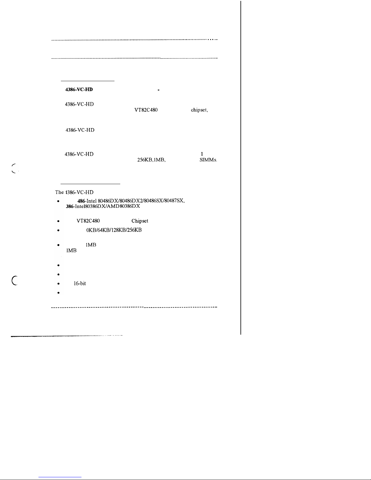
The 4386-VC-HD Cache System Motherboard
support either 486 or 386
system
The 4386-VC-HD Cache System board is a high performance system board,
utilizing the VIA Technology Inc.‘s
80486 PC/AT
that
offers outstanding features and performance for building advanced personal
computers or workstations.
The 4386-VC-HD Cache System board can easily upgrade from 386DX
system to 486DX system, and simultaneously use a 386 and 486 CPU.
High-speed Memory
The 4386-VC-HD Cache System board is capable of accommodating
to 128
megabytes of on-board memory, using
lMB, 4MB or 16MB SIMMs.
SPECIFICATIONS
Cache System board comes with the following features:
Both 486-Intel80486DX/80486DX2/80486SX/80487SX, and
PQFP and PGA packages.
VIA
80486 PC/AT Chipset for high performance.
Supports
of direct mapped write-back
cache memory.
Supports
up to 128MB of DRAM memory for 486 system,
up to 32MB for 386 system; provides page mode DRAM
operation.
Shadow RAM for fast BIOS access.
64KB User-friendly BIOS.
Six
expansion slots.
Real time clock/calendar.
1
Page 4

INTRODUCTION
MOTHERBOARD LAYOUT
COPROCESSOR
CLK
1
J9
SPEAKER
KEYBOARD
CONNECTOR
1
BANK1
J7
RESET
J6
TURBO
SW
POWER
CONNECTOR
Page 5

SYSTEM BLOCK DIAGRAM
CPUADDRESS
PERIPHERAL
DATA BUS
ISA BUS
SYSTEM ADDRESS BUS
SYSTEM
ADDRESS
BUS
Page 6

INTRODUCTION
COPROCESSOR PGA SOCKET
80486
pin Al
l
l
l
l
l
l
l
l
l
l
l
l
l
l
l
l
l
l
l
l
l
l
l
l
l
387DX pin Al
PGA socket diagram
Page 7

INSTALLATION
. . .
, . . . . .
CONNECTOR
JUMPER PINOUTS
Jumper
CN2
Function
Pin outs
Signal name
Turbo LED
1.
2.
Turbo signal
Hardware reset
1.
Ground
2.
Reset signal
Speaker connector
1.
Speaker sign
2.
NC
3.
Ground
4.
+ 5v
Key lock
1.
Power signal
power LED 2.
Spare
3.
Ground
4.
5.
Ground
Power connector
1.
Power good
2.
+ 5v
3.
+
4.
-12v
5. 6. 7.
8.
Ground
9.
-5v
10. 11.
12.
+
Keyboard connector 1.
Keyboard
2.
Keyboard da
3.
No connectic
4.
Ground
5.
+
al
ta
Page 8
INSTALLATION
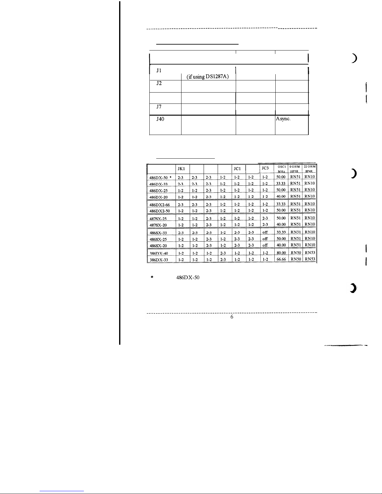
JUMPER DESCRIPTION
Jumper
Function
Open Close
RTC reset
Normal
Reset
J6
DS1287A)
Display type
CPU speed
(Turbo switch)
Hardware reset
(Reset)
Coprocessor clock
(default)
Mono/EGA/
VGA (default)
Turbo
Color
Normal
Normal
Reset
Sync. mode
l-2 shorted
(default)
2-3 shorted
CPU SELECTION
JK2 JK3
JK4
JC2
Note: the
CPU cannot be used in conjunction with any other
processors.
Page 9

MEMORY SYSTEM
MEMORY CONFIGURATION
Memory
Bank 0 Bank 1
2MB
17MB
4MB
lMx4
5MB
lMx4
20MB
68MB
16MB
17MB
20MB
32MB
64MB
65MB
68MB
128MB
The memory sizes marked with a star are for use in
486 systems only.
Page 10
MEMORY SYSTEM
CACHE RAM
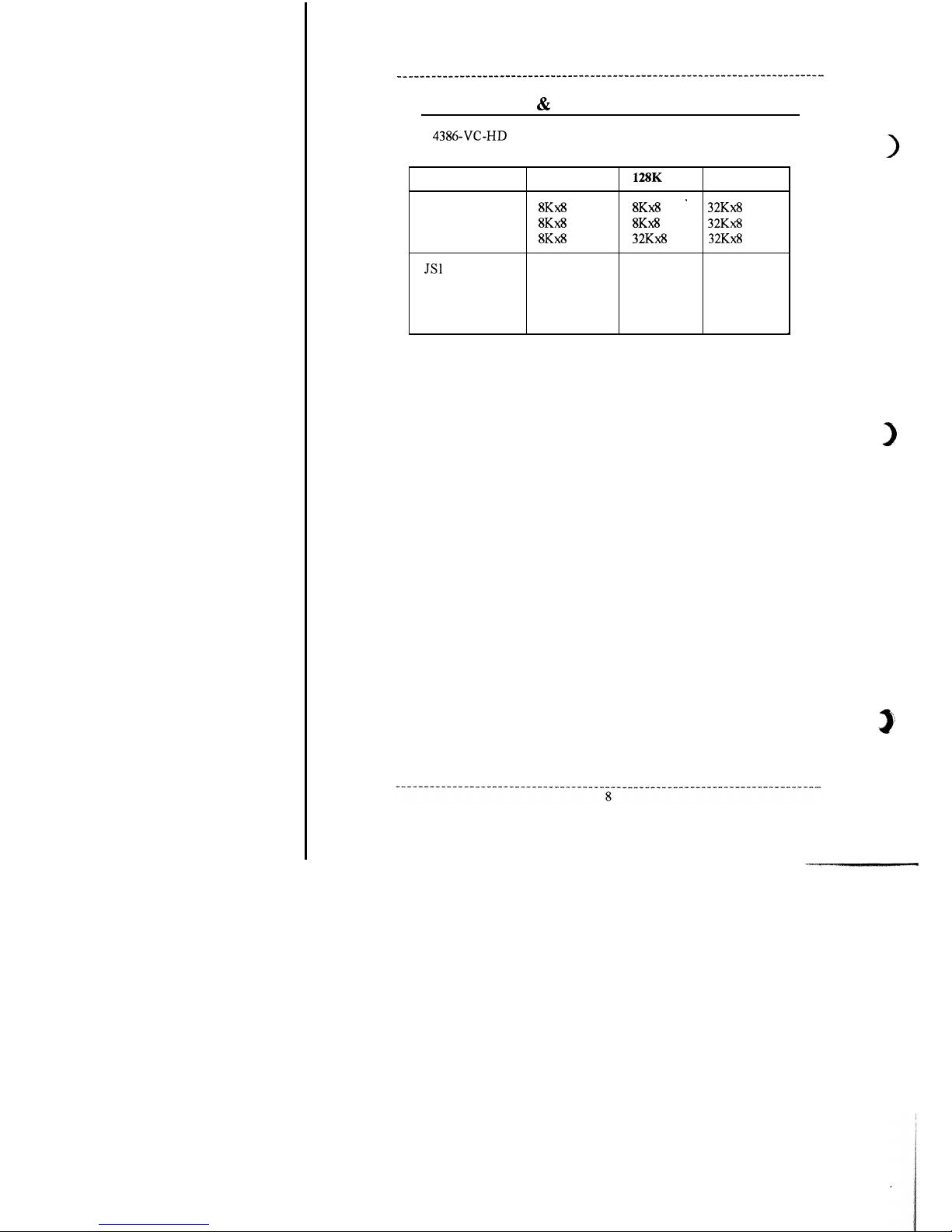
CONFIGURING CACHE SIZE
The
Cache System board uses four jumpers to configure the
cache size.
ALTER RAM
TAG RAM
DATA RAM
JS2
JS3
JS4
64K
l-2 shorted
l-2 shorted
l-2 shorted
l-2 shorted
256K
l-2 shorted 2-3 shorted
2-3 shorted 2-3 shorted
2-3 shorted l-2 shorted
2-3 shorted l-2 shorted
Page 11
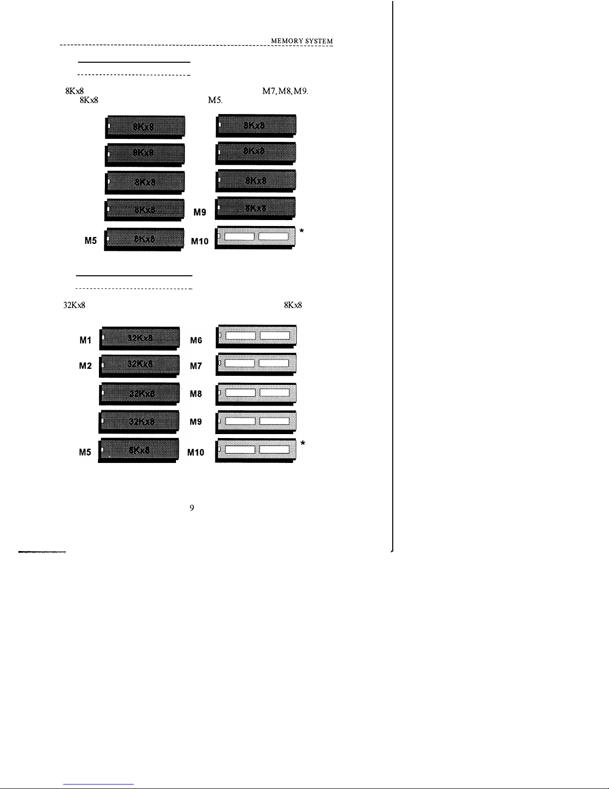
64Kbytes Direct Mapped Cache
The 64Kbytes Direct Mapped Cache option is achieved by installing eight
SRAM (DATA RAM) in Ml, M2, M3, M4, M6, M7, M8,
Install
one
SRAM (TAG RAM 28 pin) in
Ml
M6
M2
M7
M3
M8
M4
128Kbytes Direct Mapped Cache
The 128Kbytes Direct Mapped Cache option is achieved by installing four
SRAM (DATA RAM) in Ml, M2, M3, M4. Install one
SRAM
(TAG RAM 28 pin) in MS.
M3
M4
Page 12

CACHE RAM
CONFIGURING CACHE SIZE
The 4386-VC-HD Cache System board uses four jumpers to configure the
cache size.
64K
ALTER RAM
TAG RAM
DATA RAM
l-2 shorted
JS2
l-2 shorted
JS3
l-2 shorted
JS4
l-2 shorted
l-2 shorted
2-3 shorted
2-3 shorted 2-3 shorted
2-3 shorted l-2 shorted
2-3 shorted l-2 shorted
Page 13

256Kbytes Direct Mapped Cache
The 256Kbytes Direct Mapped Cache option is achieved by installing eight
SRAM (DATA RAM) in Ml, M2, M3, M4, M6, M7, M8,
Install
one
SRAM (TAG RAM 28 pin) in
Ml
M2
M3
M4
0 is A
RAM, it is optional.
M6
M7
M8
Ml0
Page 14
AWARD
BIOS SETUP
. . . . .
. . . . . . . .
. . . ..I..
. . . . . . . .
. . . . . . . .
. . . . .
..I........
SETUP SYSTEM CONFIGURATION
A setup program has been built into the system BIOS so the configurations
stored in the CMOS RAM can be changed. This program should be executed
only after:
User has changed system configuration.
User has changed system backup battery.
System has detected a configuration error and has asked the user to run
the setup program.
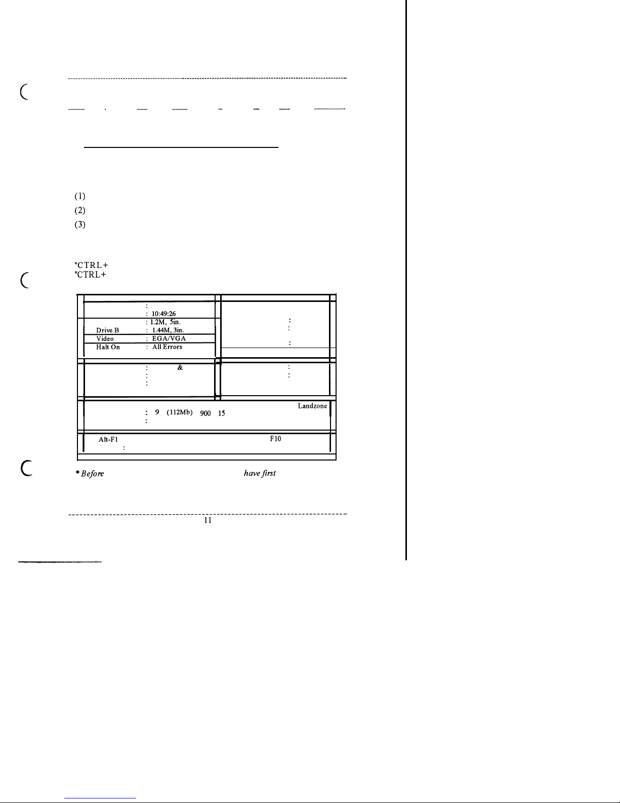
After power-on RAM testing, the message: “TO ENTER SETUP BEFORE
BOOT PRESS CTRL-ALT-ESC” is displayed on the screen. Press
ALT+ ESC” to run setup or do nothing to bypass. If the
Date
13 Jan 1992
Time
Drive A
Cache
Shadow
Security
External
Internal
System & Video
Disable
ROM ISA (486)
Award Software, Inc.
Base Memory
64K
Extended Memory
3072K
Expanded Memory: OK
0 ther Memory
384K
Total Memory
: 4096
Boot Sequence
A, C
Virus Warning
Enable
CYL Head Sector Precomp
Drive C
17
None
901
Drive
D
None(****Mb)
0 0 0 0 0
for Menu Help
Page 01
Status Page
PgDn = Options Page
F2 change colors
disable the system &video shadow, you
to disable the video
cacheable and system cacheable function in the options page setup.
Page 15
STATUS PAGE SETUP
The setup program is completely menu-driven. Use the arrow keys to select
an entry; keys to change an entry; and
10” key to exit. Help messages
are displayed in the window on the screen.
If this option is chosen then the screen above is displayed. System BIOS
automatically detects memory size, thus no changes are necessary. After the
changes are made, press
10” to exit.
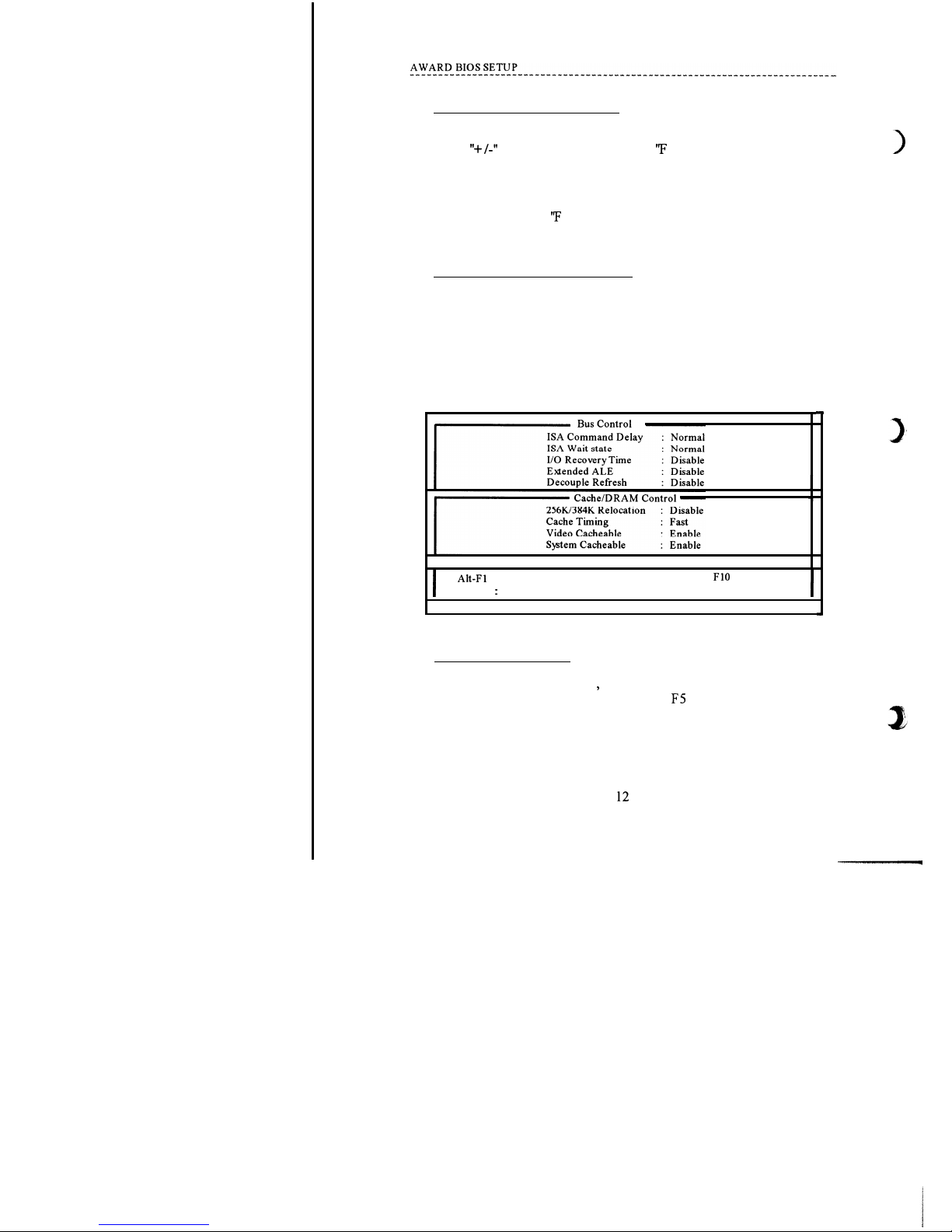
OPTIONS PAGE SETUP
The Options Page Setup program functions the same way as the status page
Setup, as shown below.
Users are not encouraged to run the status page Setup program, as your
system should have been fme tuned before shipping. Improper setup may
cause the system to fail, so consult your dealer before making any changes.
for Menu Help
PgUp = Status Page
Page 02
Options Page
F2 change colors
SAVE AND EXIT
Once you have completed Setup
then press F 10 to exit. If you did not make
any changes, press F 1 to exit; otherwise, press FS to save and exit.
Page 16

HARD DISK SPECIFICATIONS
. . . . .
. . . . .
. . . . . _.._.._.._..I . . . . .
. . . . .
. . . . .
. . . . .
CONNER
Model
Capacity Cylinder
Head
Sector
CP-3ooo
40MB
977
5 17
CP-30064
60MB
762
4
39
I
CP-30064H
60MB
762
4
39
I
I
CP-30084
85MB
526
8
39
I
CP-30084E 85MB
526
8
39
I
I
CP-30104
8
39
I
CP-30104H
8
39
I
CP-30174
903
8
46
I
CP-30174E
8
46
I
CP-30204
200MB
683
16
38
I
683
16
38
 Loading...