

Swimming Pool Heat Pump
—Operation and Installation Manual—
MODEL
FH-020

CONTENTS
INTRODUCTION
Index...........…………………………………......................................……………………………......…………... 2
The unit ………………………………………………………………………………………………………….................. 2
SAFETY INSTRUCTIONS …………………………………………………………………………………………... 4
Electrical Installation Warning ….………………………………………………………………………………………….… 4
Location Warning……………………………………………………………………………………………………………… 5
CONTENTS OF THE BOX …………………………………………………………………………………………….…… 6
OVERVIEW OF THE UNIT ……………………………………………………………………………………….……… 7
EXPLODED VIEW…………………………………………………………………………………………….…………………. 8
INSTALLATION …………………………………………………………………………………………….…..….…….… 9,10
Installation AREA …………………………………………………………………………………………….…..….....…. 9
Optimize your installation .………………………………………………………………………….…………………… 9
Water connection …………………………………………………………………………………..…………….………….. 9
Electrical connection ……………………..……………………………………………………………………….….……… 9
Trial running …………………………………………………………………………………………….……..……………….. 10
OPERATING THE UNIT …………………………………………………………………………………………….……… 11
Features and functions …………………………………………………………………………………………….……….. 11
User interface ……………………………………..…………………………………………………………………………… 11
Buttons …………………………………………………………………………………………….……………………….… 12
System fault table…………………………………………………………………………………………………………… 13
PARAMETER CODES, ERROR CODES …….....……………………………….……………….……………. 13
Parameter list ….........………………………………………………………………………….……………………. 14
MAINTENANCE …………………………………………………………………….……………………………………….. 15
TROUBLESHOOTING …………………………………………………………….………………………………………… 16
ENVIRONMENTAL INFORMATION ……………………………………….………………………………………… 17
WIRING DIAGRAM …………………………………………………………….…........……………………………. 18
WARRANTY INFORMATION…………………………………………….……………………………………………. 19
READ THIS MANUAL CAREFULLY BEFORE STARTING UP THE UNIT. DO NOT THROW IT AWAY.
KEEP IT IN YOUR FILES FOR FUTURE REFERENCE.
BEFORE OPERATING THE UNIT, MAKE SURE THE INSTALLATION HAS BEEN CARRIED OUT BY A LICENSED
AND COMPETENT PROFESSIONAL . IF YOU FEEL UNSURE ABOUT INSTALLATION OR OPERATION,
CONTACT YOUR DEALER FOR ADVICE AND INFORMATION.
2

INTRODUCTION
This manual includes all necessary information about the unit. Please read this manual carefully
before you use and maintain pump.
The unit
The swimming pool heat pump is one of the most economical systems to heat swimming pools
efficiently. Using the free, renewable energy from the air, it delivers up to 6.2 times more energy in
heating than a traditional heating system such as a gas boiler or electric heater, saving 85% on energy
costs. The swimming pool heat pump provides comfortable swimming temperatures year round in
milder climates and extended swimming seasons in the cooler/ drier climates
Ecological and economical heating
By making use of the renewable energy in the outside air, it consumes much less energy with low
carbon emissions. Utilizes environmentally and ozone-friendly technology, R410A.
Titanium heat exchanger
Advanced titanium heat exchanger guarantees a long life span and protects against the damaging
effects of corrosion or rust. By using a titanium heat exchanger, the heat pump is compatible with
all types of water treatment such as chlorine, bromine and salt.
Multiple functions
- Cooling and heating functions
- Auto-operation, Auto-restart, Auto defrost
- Timer on/off: no attendance is required
- Wide ambient working condition: -5°C to 43°C (23°F to 109°F)
Reliable operation
To guarantee the stable operation and safety of the unit, multiple protection devices have been
built into the design, including insufficient water flow protection, high/low pressure protection,
overload protection and compressor protection.
Safe use
The unit runs without oil, gas or any other hazardous substance, removing the risk of intoxication,
smell, combustion, pollution from leakage.
Self-diagnosis
In case of a malfunction, the pump will make a self-diagnosis by displaying an error code on the
control panel, no guesswork necessary.
3

SAFETY INSTRUCTIONS
To prevent injury to the user, others, or property damage, the following instructions must be carefully
followed. Ignoring these instructions may result in injury or death.
Install the unit only if it complies with local codes, by-laws and standards. Check the main voltage and
frequency. This unit is only suitable for grounded circuits, connection voltage 220 – 240 V ~ / 60Hz. It
cannot be converted to 120 volts.
The following safety precautions should always be taken into account:
- Be sure to read the following WARNING before installing the unit.
- Be sure to observe the cautions specified here as they include important items related to safety.
- After reading these instructions, be sure to keep them in a handy place for future reference.
Installation must be done by a licensed and competent professional
Incorrect installation could cause injury or death due to fire, electric shock, the unit falling or leakage of
water. BE SURE ALL LOCAL CODES ARE FOLLOWED.
Use the specified electrical wires and attach wires firmly to the terminal board (connection in such a
way that the stress of the wires is not applied to the sections).
THIS UNIT REQUIRES 220-240 VOLTS, AC, 60 Hz, 20 Amp DUAL BREAKER WITH APPROPRIATE SIZE WIRE.
The weather-proof wire provided with the unit is 8 feet long. Some municipalities DO NOT authorize
usage of weather-proof wires, and require conduit protection.
This unit runs on 220 - 240 volts only. It cannot be used with 120 volts electricity
Be sure to use the provided or specified parts for the installation work.
Be sure to use the 'EQUIPOTENTIAL BONDING CONNECTION “ on the chassis of the heater. Please
connect this bond to a minimum of #8 copper wire; along with the rest of the metal parts around the
pool, in accordance with NEC 2005 -680.26 Electrical code.
The unit must always have a GROUNDED connection, as well as a bonding connection
Do not use an extension cord to connect the unit to an electrical power supply.
Do not move/repair the unit yourself.
Before proceeding with any maintenance, service or repair work, electrical lines must be
DISCONNECTED. Only a licensed/competent technician should work on this unit.
Use only Genuine FIBROPOOL® PARTS for replacement. All parts can be obtained from Fibropool,
www.fibropool.com
4

Do not install the unit in a place where there is a fire hazard:
GAS LEAKS. If there is a gas leak and gas accumulates in the area surrounding the unit, it could cause
an explosion.
UNDER THE ROOF EAVES . Although the unit is weatherproof, a direct pour of water from the roof is
likely to penetrate the shell and cause a shortage. Please install the heater in an open area exposed to
weather, but not beneath the roof line
ON A WET SURFACE. Wet areas will cause metal corrosion and shorten the life of your heater
LOWER THAN SURROUNDING AREAS. Install your heat pump on an equipment pad or concrete blocks
to prevent accumulated water from entering the unit from bottom.
IN ENCLOSED AREAS. The heat pump needs fresh air to operate. Do not install in equipment rooms or
enclosed areas. If this is a must, be sure to install an air fan to supply fresh air to the room, at a rate of
NO LESS THAN 3,000 cfm.
Do not open the unit when the power is ‘ON’.
Always shut ‘OFF’ the power by disconnecting the supply breaker or service disconnect when cleaning
or servicing the unit. Electrical shock, Injury or death can occur, as the unit works on HIGH voltage
Do not continue to run the unit when there is something wrong or there is a strange smell.
The service disconnect must be pulled off or breaker turned off in case of any suspicious condition.
Do not put your fingers or other items into the fan.
The ventilator runs at high speeds, potentially causing serious injury.
Do not block the drain holes on the bottom.
The unit will SWEAT heavily during operation. This is commonly mistaken for a leakage, but is
actually CONDENSATION, moisture in the air draining.
Provided elbow can snap to the bottom of the heater and may be directed by attaching a hose.
5
CONTENTS OF THE PRODUCT BOX
Before starting the installation, please make sure that all parts are found inside the box.
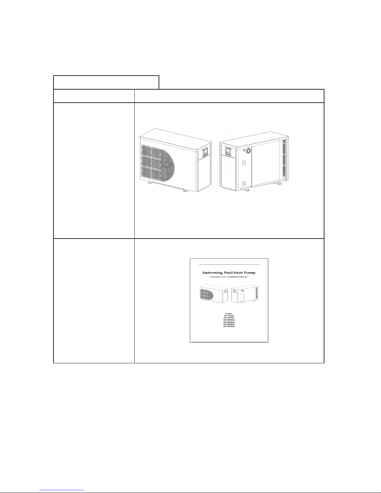
The Unit Box
Item Image
*Swimming pool heat pump
**Operation and Installation
Manual
***Union set
****Drain adapter elbow
( inside the service panel)
6

OVERVIEW OF UNIT
Unit Dimensions Required Clearance
A - Height
1'-10” 12”- top
B - Length
3'-0” 36” on service panel side, 12” on the far side
C - Width
1'-3” 12 “ on both sides
7

EXPLODED VIEW
1
Cover
10 Chassis 19
Controller
2
Fixed frame 11 Fan motor 20 Controller mounting board
3
Front panel 12 Compressor 21 Four way valve
4
Wire controller 13 Evaporator 22 Titanium heat exchanger
5
Copper tube 14 PCB 23 EEV
6
Motor bracket 15 Support column 24 Low pressure switch
7
Left side panel 16 Rear side panel 25 High pressure switch
8
Guide air circle 17 Pressure gauge 26 Copper tube
9
Fan blade 18 Cable fixing head 27 Maintenance panel
8

INSTALLATION
Installation area
Install the unit on a flat, horizontal and stable surface. An HVAC equipment pad is ideal, although 4“ thick
concrete blocks will work as well.
To optimize installation
Allow a minimum of 12” of clearance on all 3 sides, but ensure 36” in front of the service panel
Water connection
The heat pump can be connected to the filtration circuit by one of two methods:
1. With a 3-valve
bypass, placed after the pump and filter. This allows the user to regulate water flow to the pump and
isolate the unit completely for maintenance.
2. Inline with the
system. This will somewhat reduce the flow rate of the filtration system on large circulation pumps.
NOTE
If your pool has a water treatment system (chlorinator, salt generator, brominator etc...) installed, the bypass
must be installed before the water treatment. A check valve after the heater, before the treatment system is
recommended but not required.
Electrical connection
Electrical supply must be installed by a licensed electrician. This unit uses a double pole, 230-240 Vac, 60 Hz
circuit, with a 20-amp breaker. The unit will use a maximum of 9 amps of electricity during operation.
9

Trial running
After connecting water to the pool system perform a test run.
Ensure that:
Appliance is horizontal and on a firm base.
Plumbing is firmly connected, using the approved type of pvc primer, glue or couplings.
Electrical wire is firmly connected (all screws tightened correctly at terminals and intermediate
circuit breaker), insulated and GROUNDED correctly.
TURN ON YOUR POOL CIRCULATING PUMP “ON”
TURN ON THE BREAKER FOR THE HEATER
TURN ON YOUR HEATER WITH THE “ON/ OFF” SWITCH
OBSERVE THAT THE HEATER STARTS WITHIN 1 MINUTE BY KEEPING AN EYE ON THE PRESSURE
GAUGE.
ONCE THE HEATER TURNS ON, PRESSURE WILL CLIMB. LEAVE IT RUNNING FOR 5 MINUTES TO ASSURE THAT
ALL PARAMETERS ARE CORRECT
◦
ATTENTION: THE HEAT PUMP ONLY FUNCTIONS WHEN WATER FLOW IS PRESENT.
10

OPERATING THE UNIT
Operating the unit is done by the controller ONLY.
There will be NO NEED to open the service panel for operations
NEVER LET THE DIGITAL CONTROLLER GET WET. THIS MAY LEAD TO AN ELECTRICAL SHOCK OR FIRE.
NEVER PRESS THE BUTTONS OF THE DIGITAL CONTROLLER WITH A HARD, POINTED OBJECT. THIS
MAY RESULT IN DAMAGE.
NEVER SERVICE THE DIGITAL CONTROLLER. THEY ARE SOLID STATE CONTROLLERS WITH NO MOVING
PARTS INSIDE.
Features and functions
Basic controller functions
The basic controller functions are:
Unit ‘ON’/’OFF’.
24-hour, real-time clock.
Timer ‘ON’ and timer ‘OFF’.
Parameter adjustment
User interface
LED cooling and heating controller interface
11

Buttons
Unit ON/OFF button
USE THIS BUTTON TO TURN THE UNIT ON or OFF.
Unit is ON when clock, running mode and timing state are displayed on screen.
Mode button
Press this button to select the running mode at any time. Each time this button is pressed, the
HEATER will cycle between one of four modes IF AVAILABLE. It will illuminate the Mode the heater is
in, such as “Heating” or “Cooling”
Timer ON button
Press this button when the unit is not in clock setting. Set desired hour and minute, then press
once more to exit timing boot setting. In the corresponding conditions, press“ ” to set the ▲▼
corresponding time value.
Timer OFF button.
Press this button when the unit is not in clock setting condition, the unit can be turned into timing
shutdown setting condition, press this button again to set hour and minute ,press it one more time
to exit timing shutdown setting. In the corresponding conditions, press“ ”Set the corresponding▲▼
time value.In timing shutdown setting condition,press “”can cancel timing shutdown function.
Timer Button
Press “” directly entering into Timer Settings, the“88.88”flashing, then press“”to set Hour with“ ”▲▼
,and press “” again to set Minute with “ ”,then press again to save and complete settings.In▲▼
Timer Setting condition, “”button and “”button invalid.
“ ”or“ ”Button:▲ ▼
Used for the temperature setting, parameter setting, parameter checking, and adjustment of the
timer.
In clock Setting,they are used for adjusting hour and minute
In turn ON/OFF timing setting,they are used for adjusting hour and minute;
In normal condition, press “”button for 5 seconds to enter parameter checking interface, at this
time press “”again enter into parameter setting;In other condition,at the same time
Press“ ”and“ ”5 seconds enter into keyboard lock,press it again at the same time for 5 seconds▲ ▼
exit the keyboard lock.
Press BOTH for 10 seconds, wire control parameter are reset.
12

SELF DIAGNOSTIC SYSTEM CODES AND ERRORS:
Protection/
Malfunction
remote
controller
LED indicator
Standby Dark
Normal operation Bright
Lower tank water temp.
sensor failure
PP 1 ● (1 flash 1 dark)☆
Upper tank water temp.
sensor failure
PP 2 ● (2 flashes 1 dark)☆☆
Evaporator coil temp.
sensor failure
PP 3 ● (3 flashes 1 dark)☆☆☆
Return air temp. sensor
failure
PP 4 ●(4 flashes 1 dark)☆☆☆☆
Ambient temp. sensor
failure
PP 5 ● (5 flashes 1 dark)☆☆☆☆☆
Cooling coil heat failure PP 8 ●( 11 flashes 1 dark)☆☆☆☆☆☆
In and out of the water
temperature difference is
too large to protect
PP 6 Bright
Refridgeration cold
protection
PP 7 Bright
Winter level 1 antifreeze
protection
PP 7 Dark
Winter level 2 antifreeze
protection
PP 7 Dark
High pressure protection EE 1 ●(6 flashes 1 dark)☆☆☆☆☆☆
Low pressure protection EE 2 ● (7 flashes 1 dark)☆☆☆☆☆☆☆
Flow failures
ON
EE 3
● (8flashes 1 dark)☆☆☆☆☆☆☆☆
Phase sequence protection EE 4 ● (9flashes 1 dark)☆☆☆☆☆☆☆☆☆
In and out of the water
temperature difference is
too large fault
EE 5 ● (10flashes 1 dark)☆☆☆☆☆☆☆☆☆☆
Defrost
Defrosting
indication
……(a long flashes)☆☆☆☆☆☆☆☆
Communication failure
EE 8 The fault is available for remote controller only
IF THERE IS INSUFFICIENT WATER FLOW OR A FLOW SENSOR MALFUNCTION, THERE WILL BE AN
ERROR DISPLAYED: “EE03”
13

PARAMETER CHECK AND ADUSTMENT
Parameter list
Some parameters can be checked and adjusted by the controller. Below is the parameter list.
Parameter Explanation Range Default
value
Remarks
0
Cooling water cycle temperature
value
15-35℃(59~95℉) 82℉(24℃) Adjustable
1
heating water cycle temperature
value
15-40℃(59~104℉) 82℉(24℃) Adjustable
2 The interval for defrosting 30~90Min 40Min Adjustable
3
Defrosting entry coil
temperature
-30-0℃(-22~36℉) -7℃(19℉) Adjustable
4 Defrosting-off coil temp. 2-30℃(36~86℉) 20℃(55℉) Adjustable
5 Defrosting max. lasting time 1~12Min 8Min Adjustable
6
Unit mode selection (heating
only/heating and cooling)
0~1
1(heating and
cooling)
Adjustable
7
electronic expansion valve
adjustment
0~1 1(auto) Adjustable
8 Heating target over-heat degree -15~15℃(5~59℉) 3℃(37℉) Adjustable
9 cooling target over-heat degree -15~15℃(5~59℉) -2℃(28℉) Adjustable
A Electronic expansion valve step 18~94 70*5 Adjustable
b Inlet water temp (-9~99℃)-4~210℉
Actual
Reading
C Outlet water temp (-9~99℃)-4~210℉
Actual
Reading
d Heating coil temp (-9~99℃)-4~210℉
Actual
Reading
E Return gas temp. (-9~99℃)-4~210℉
Actual
Reading
F Ambient air temp. (-9~99℃)-4~210℉
Actual
Reading
G Cooling coil temp (-9~99℃)-4~210℉
Actual
Reading
H
Electronic expansion valve
practical count
N*5
Actual
reading
L
Inlet water temp calibration
parameter
(-9.9-~9.9)14~50℉ 0℃ Adjustable
14

MAINTENANCE
To protect the chassis, avoid placing objects on the device. External heat pump parts can be wiped with
a damp cloth and household cleaner. (Note: Never use cleaning agents containing sand, soda, acid or
chloride as these can damage the surface)
To prevent malfunctions due to sediment in the titanium heat exchanger, ensure that the heat
exchanger cannot be contaminated. In the event that operating malfunctions occur due to
contamination, the system should be cleaned as described below. (Warning: the fins on the tube heat
exchanger have sharp edges-use caution to avoid injury)
Cleaning the pipe system in the heat exchanger
Contamination in the pipes and heat exchanger can reduce the performance and efficiency of the pump.
Pressurized drinking water should be used by a technician to remove any of these substances.
Cleaning the air system
The finned heat exchanger, ventilator and condensation outflow should be cleaned of debris (leaves,
twigs, etc...) before each season. These types of contaminants can be manually removed using
compressed air or by flushing with clean water. It may be necessary to remove the device cover and air
inlet grid first.
The external fins can be cleaned with a spray on air conditioner condenser cleaner.
Note: Before opening the device, ensure that all circuits are isolated from the power supply.
To prevent the evaporator and condensation tray from being damaged, do not use hard or sharp objects
for cleaning. Under extreme weather conditions, ice may form on the air intake and exhaust air outlet
grids. If this happens, all ice from these grids must be removed to ensure that the minimum air flow rate
is maintained.
Winter Shutdown/Lay-up
If the outdoor temperature is expected to drop below the pump's operating limit (-5°C or 23°F) after the
swimming season has ended, the water circuit of the heat pump should be completely drained to avoid
damage.
For this, simply disconnect the unions, and lean the heater 45' degrees to the side of the connections.
This will remove most/ all standing water from the tank. If you are not confident that all water has been
removed, simply insert a wet-dry vacuum hose into the bottom water port and vacuum out the
remaining water.
Attention: Warranty does not cover damages to the heat exchanger tanks.
15

TROUBLESHOOTING
This section provides useful information for diagnosing and correcting certain issues which may occur.
Before starting the troubleshooting process, carry out a thorough visual inspection of the unit and look
for obvious defects such as loose connections or defective wiring.
Before contacting your local dealer, read this chapter carefully, it will save you time and money.
WHEN CARRYING OUT AN INSPECTION OF THE SWITCH BOX OF THE UNIT, ALWAYS ENSURE THE
MAIN SWITCH OF THE UNIT IS SWITCHED ‘OFF’.
The guidelines below may help to solve your problem. If you cannot solve the problem, consult your
installer or local dealer.
1.877.FIBROPOOL
1.877 342-7676
support@fibropool.com
The heat pump will not run.
Please check whether:
There is supply of proper voltage (tripped fuse, power failure). Please be sure 230-240 volts is read
on the multimeter. OFTEN 1 SIDE OF THE BREAKER TRIPS AND OTHER SIDE SUPPLIES 120 V, WHICH
FEEDS BACK AND YOU CAN GET A 120 V READING ON BOTH TERMINALS. But this is a false reading.
Be sure to read 230-240 volts between the supply lines
The operating switch on the wired controller is switched ON, and whether the correct set point
temperature has been set.
The set temperature level cannot be reached.
Please check whether:
The permissible operating conditions for the heat pump have been adhered to (air temperatures
too high or too low).
The air inlet or outlet area is blocked, restricted or dirty.
There are closed valves or stopcocks in the water pipes.
The scheduled timer does work but the programmed actions are executed at the wrong time (e.g. 1
hour too late or too early).
Please check whether:
The clock and the day of the week are set correctly, adjust if necessary.
If you cannot correct the fault yourself, please contact your service technician.
Work on the heat pump may only be carried out by an authorized and qualified service technician.
16

ENVIRONMENTAL INFORMATION
This equipment contains fluorinated greenhouse gases covered by the Kyoto Protocol. It should only be
serviced or dismantled by professional trained personnel.
This equipment contains R410A refrigerant in the amount as stated in the specification. Do not vent
R410A into the atmosphere: R410A, is a fluorinated greenhouse gas with a Global Warming Potential
(GWP) = 1975.
DISPOSAL REQUIREMENTS
Dismantling of the unit, treatment of the refrigerant, of oil and of other parts must be done in
accordance with local and national legislation.
Your product is marked with this symbol. This means that electrical and electronic products
shall not be mixed with unsorted household waste.
Do not try to dismantle the system yourself: the dismantling of the system, treatment of the refrigerant,
of oil and other parts must be done by a qualified installer in accordance with relevant local and
national legislation.
Units must be treated at a specialized treatment facility for reuse, recycling and recovery. By ensuring
that this product is disposed of correctly, you will help to prevent potential negative environmental
consequences. Please contact the installer or local authority for more information.
Note: *******
When repair and maintenance need to open the unit, PLEASE OPEN THE SERVICE PANEL FIRST. Your
heater has concealed screws, that can only be reached from the service panel.
17

WIRING DIAGRAM
Please refer to the wiring diagram on the electric box.
MODEL:FH 020
18

19
 Loading...