

Page 1
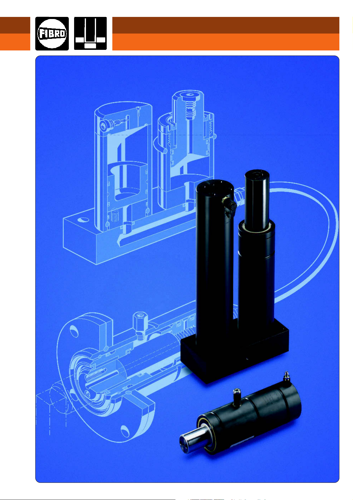
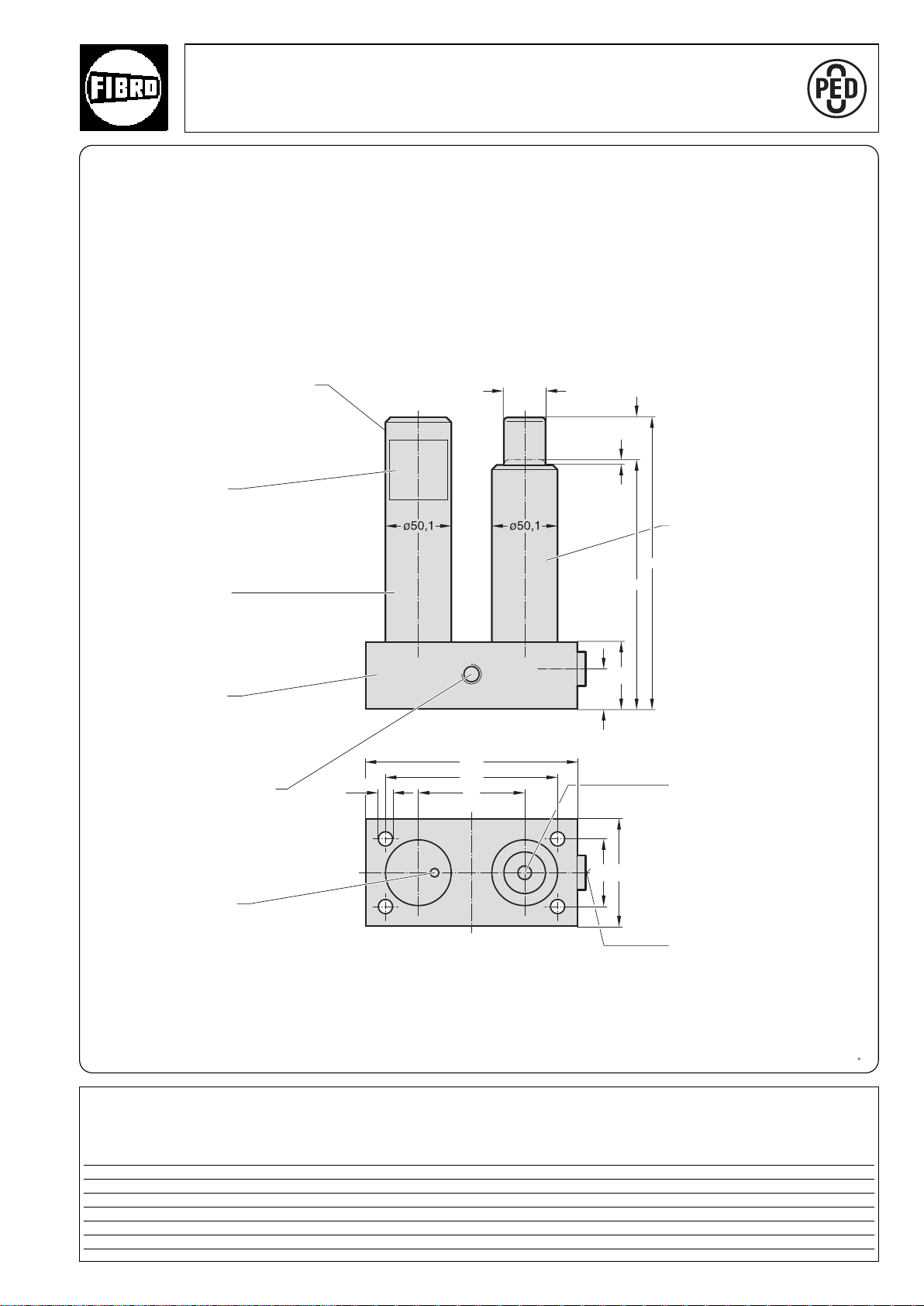
Flex Cam
Hydraulic cylinders and tool slides
for tool and mould-making and
machinery construction
Product No. 2.2901.02.1205.01000
°
09/2006
2·14175·2005· 2
Page 2
°
2·14176·2000·1
Page 3

Contents
Page
Introduction 5–6
Description 6–7
Stroke rate/Capacity and output 8
Funktion 9
Power Unit/Cam Unit combinations 10
Selecting the components 11–14
Dimensions and Order No 15–45
Cam Units
Force Cylinders
15–40–60–90–150 kN 16–22–30–36–42
Compact Cams
15–40–60–90–150 kN 18–24–32–38–43/1
Power Units
15–40–60–90–150 kN 20–28–34–40–44
Flange Cam 26–27
Electric hydraulic pump 46
Accessories 47–64
Connecting hoses 48
Threaded couplings 49–51
Quick-release couplings 52–53
Charging and control fitting 54
Oil filling unit 55
Assembly tool 56
Control fittings 57
Compound threaded joints 58
Test hoses and couplings
Pressure switches 59–60
Sensor mounting kit 61
Inductive proximity switch/
Connection cable 62
Top mounting for Flange Cam 63
Safety module 64
Safety label 65
Typical installations for monitoring
process safety 67–71
Monitoring 68–71
Typical applications 73–77
FIBRO – The latest technology –
°
with a tradition of service 78–79
2·1417·2000·1
subject to alterations
3
Page 4
General Instructions
System safety, reliability and functionality can be ensured by supplying FIBRO with the application data
and drawings of the installation arrangements for checking.
Please note that the number of the threaded connections and the hose lengths for installation in the
system must be determined.
Assembly, commissioning, maintenance and servicing of the Flex Cam system require
special knowledge and may only be carried out by FIBRO trained, specialist personnel.
You can order the work to be carried out by a FIBRO customer service engineer, to be invoiced in
accordance with our installation tariff.
Just contact us to schedule it for you.
We shall be pleased to answer any technical queries you may have, now or at any time in the future.
As the Flex Cam system which are specially made, we recommend that you keep
reserve systems in stock to avoid the risk of delay when the need arises.
°
2·14178·2000·1
4
subject to alterations
Page 5
2018. Flex Cam
2·14179·2000· 1
°
subject to alterations
5
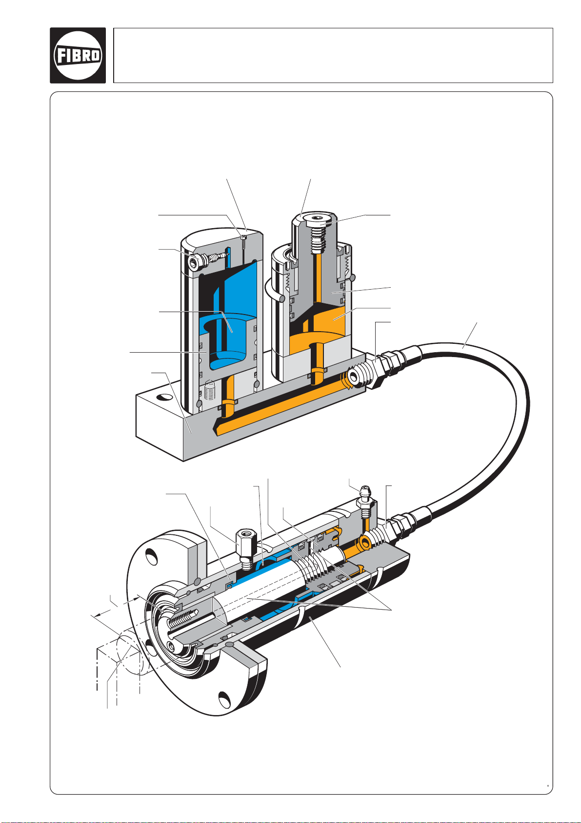
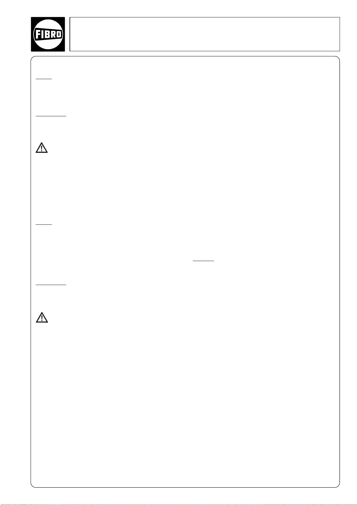
Power Unit
Cam Unit
Accumulator Power Cylinder
Oil charge connectionBurst guard
Nitrogen charge
connection
Nitrogen charge
Piston
Adapter plate
Piston rod guide, sealing
(nitrogen spring)
Limit of stroke
(external)
Duplex piston
(sealing nitrogen
and oil charges)
Piston rod
Bleeding screw
Safety hose
Force Cylinder
Nitrogen charge
Stroke
Nitrogen
charge
connection
Piston
Oil
Hydraulic hose
connection
Hydraulic hose
Hydraulic hose
connection
Page 6

Flex Cam 2018.
Introduction
The hydraulic cam system is the ideal component for executing linear motions at any
point in the available space.
The system is increasingly being used in
tool making, in particular, to drive drawing,
moulding, cutting and drilling operations
where conventional slides cannot be used
due to lack of space or inconvenient
position.
The working motion is generated by the
cam unit (e.g. the working cylinder), which
can be installed in any position in the
available space.
The cam unit is controlled by a driving
cylinder which, in turn, is activated by the
stroke motion of a press, for example.
The link between the two is provided by a
hydraulic hose in which the volume of oil in
the power unit is displaced to the cam unit.
Description
Power Unit
The Power Unit consists of the following components:
• Power Cylinder
• Accumulator
• Adapter plate
The Power Cylinder is filled with oil at one end, while
the machine that executes the stroke is at the opposite
end.
The accumulator is charged with nitrogen gas at one end.
In the idle state, the base of the piston rests on the
accumulator, relieving the pressure on the system.
The adapter plate connects the Power Cylinder to the
Accumulator and Force Cylinder.
In the standard version, the capacity of the accumulator
is matched to the total displacement volume of the
Power Cylinder. It is thus of the same height as the
piston rod. The integral rupture protection device opens
at 517 bar.
The Power Unit is also available with a separate Power
Cylinder and Accumulator.
Cam Units
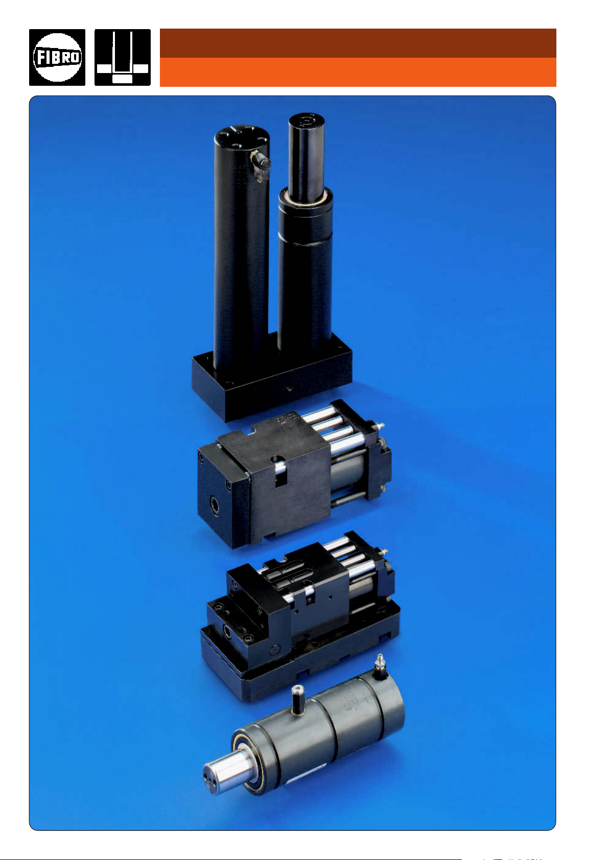
There are 3 types of Cam Units:
• Force Cylinder 2018.30./40./50./60.
• Compact Cam 2018.11.
• Flange Cam 2018.12.
Force Cylinder 2018.30./40./50./60.
Design
The accumulator is charged with nitrogen gas at one end
(20 – 40 bar). The volume of oil displaced from the Power
Unit acts on the other end when the Power Unit is pressurised. The Force Cylinder then extends. The retraction
motion is generated by the nitrogen gas when the pressure is relieved on the stroke side of the Power Cylinder.
The displacement length of the Force Cylinder is twice
as long as the permissible nominal displacement length.
The unused displacement capacity is needed as a compartment for the pressurised nitrogen gas in order to
return the stroke.
Applications
The Force Cylinder is designed to drive an individual tool
component (e.g. a slide).
The nominal stroke of the Force Cylinder must be limited
by external stops. The Force Cylinder is not guided and
therefore cannot absorb any side loads. The tool components themselves must be guided.
Side loads acting on the Force Cylinder lead to
system failure.
When attaching accessories, be careful to ensure that
the axes are lined up correctly to avoid transverse forces
during the stroke. Coupling pins or similar accessories
must be used for the connection as there must be no
rigid connection between the piston of the Force Cylinder
and the tool components.
°
2·14180·2000·1
6
subject to alterations
Page 7
2018. Flex Cam
2·14187·2000· 1
°
subject to alterations
7
Compact Cam 2018.11.
Design
The Power Cylinder starts the piston rod of the Compact Cam
moving when pressurised. The slide is returned by external gas
springs. Two pillars with guideways prevent the tool holder
plate rotating. The clearance in the guides is 0.01 – 0.03 mm.
Applications
The Compact Cam is suitable for hole punching operations
involving no transverse forces. The Compact Cam is guided and has an internal stop. Punches can be mounted
directly on the tool holder plate.
Side loads on the Compact Cam will lead to
system failure.
In cutting operations with a small cutting clearance and
asymmetrical cutting forces a guide bolster should be provided, with an external guide to absorb the lateral forces. As
with the Force Cylinder, coupling pins must be used for the
connection between the slide and the external guide
(uncoupling). The Compact Cam is attached by 4 fixing screws. A feather key groove absorbs the cutting forces. It is
positioned by means of two pilot holes.
Flange Cam 2018.12.
Design
The Flange Cam construction is the same as the construc-
tion of the Compact Cam. The Power Cylinder starts the
piston rod of the Flange Cam moving when pressurised. The
slide is returned by external gas springs. Two pillars with
guideways prevent the tool holder plate rotating. The clearance in the guides is 0.01 – 0.03 mm. The tool holder plate
is supported by a roller and a support plate to absorb lateral
forces.
Applications
The Flange Cam is suitable for work operations with lateral
forces (e.g. bend up, sliding). The Compact Cam is guided
with an integrated stop. Punches can be mounted directly
on the tool holder plate.
A guide bolster with external guide should be provided for bending operations with asymmetrical
forces.
The Flange Cam is attached by 4 fixing screws. A feather
key groove absorbs the bending forces. It is positioned by
means of two pilot holes.
Alternative drive
For operating the Cam Unit electrically powered Hydraulic
pump units can be used (see page 46). The max. working
pressure must not exceed 150 bar. The max. speeds listed
on page 8 must not be exceeded.
Charging fittings
Nitrogen gas: The Accumulator and Cam Unit can be charged with the gas spring filling charge 2480.00.32.21.
Hydraulic system: The system is filled and vented using
the oil filling unit 2018.00.30.
Filling and venting of the system is described in detail in
the user manual supplied with the system.
Hydraulic connection
See also pages 48-53
User-friendly, flexible high-pressure hoses are ideal for the
hydraulic connections (see page 48).
A space-saving alternative is to use system hydraulic
pipes.
The same screwed couplings are used for both hoses and
pipes.
The hose length should not exceed 2000 mm. This is
important to ensure a constant build-up of pressure and –
even more importantly – to minimise impact during cutting
without a significant pressure build-up.
The couplings should be designed for at least 300 bar
nominal pressure and 1000 bar rupture pressure.
This is essential if the connection is to be sufficiently rigid
and for the rupture protection device to operate at 517 bar.
Quick-release couplings for hydraulic
hoses
We recommend that you use quick-release couplings to
join the hydraulic hoses.
Benefits:
• The system can be filled and vented under optimum conditions when off the tool, either at FIBRO or on site.
• If the tool has to be assembled or dismantled, the
hydraulic hose connecting the Power Unit and the Cam
Unit is disconnected using the quick-release coupling.
It is thus not necessary to dismantle the hoses, drain and
refill the oil and vent the system, which keeps costs
down.
For layout purposes, the dimensions of the commonly
used threaded couplings and hoses are shown on pages 48
to 53.
Leaks and oil level display
The experience we have gained in manufacturing gas
springs enables us to select the most suitable seals.
The result is an effective and long-lasting seal.
The connecting line can be assembled with no leaks, using
available materials and with careful installation.
If an oil leak does occur, it will be compensated short term
by the overtravel volume in the Accumulator.
The Accumulator and Power Cylinder are of the same
height, so any loss of oil from the system will be manifested by a difference in height.
Page 8
Flex Cam
Stroke rate
The stroke rate is dependent on the minimum flow
opening, the volume of oil and the working and return
pressures. The connecting openings allow a working
stroke rate of up to 0.8 m/s. Although this is limited by
the extent to which the system heats up due to the
high stroke rates. The system temperature should not
exceed 60 °C.
Safety instructions
If the layout of the system gives the Force Cylinder an
excessive displacement volume due to excess overtravel and/or seizing of the cylinder, the pressure in the
system can exceed the admissible value of 280 bar. In
critical situations, this effect will be counteracted by
the opening of a rupture valve at 517 bar.
The couplings are designed for a nominal pressure of
300 bar and 1000 bar rupture pressure.
On the gas side, the Accumulator is pressurised at 150
bar and is subject to Pressure Equipment Directive
97/23/EC.
To monitor safety during the process, we recommend
installing a control fitting as an additional check on the
gas side - see range of accessories.
Capacity and output
The forces listed in table 1 below are applicable for the
following nitrogen gas pressures:
Accumulator 150 bar
Force Cylinder 20 bar
Compact Cam
2018.11.01500.. and 2018.11.04000.
Gas spring 2480.21. and .23.00000. 180 bar
2018.11.06000.
Gas spring 2487.12.00350. 180 bar
Compact Cam
2018.11.09000.
Gas spring 2480.12.00500. 150 bar
2018.11.15000.
Gas spring 2487.12.00750. 150 bar
Flange Cam
2018.12.04000.049
Gas spring 2480.21. and .23.00000. 180 bar
Comments
The Accumulator and the Force Cylinder are pressure
vessels and as such are subject to the Pressure Equipment Directive 97/23/EC.
During cutting and hole punching operations the nominal force of the Compact Cam should only be utilised
up to 75% to minimise impact during cutting which is
reinforced by the Accumulator. Impact during cutting
can be reduced by polished tool edges (e.g. roof
shape) and so downtime can be reduced.
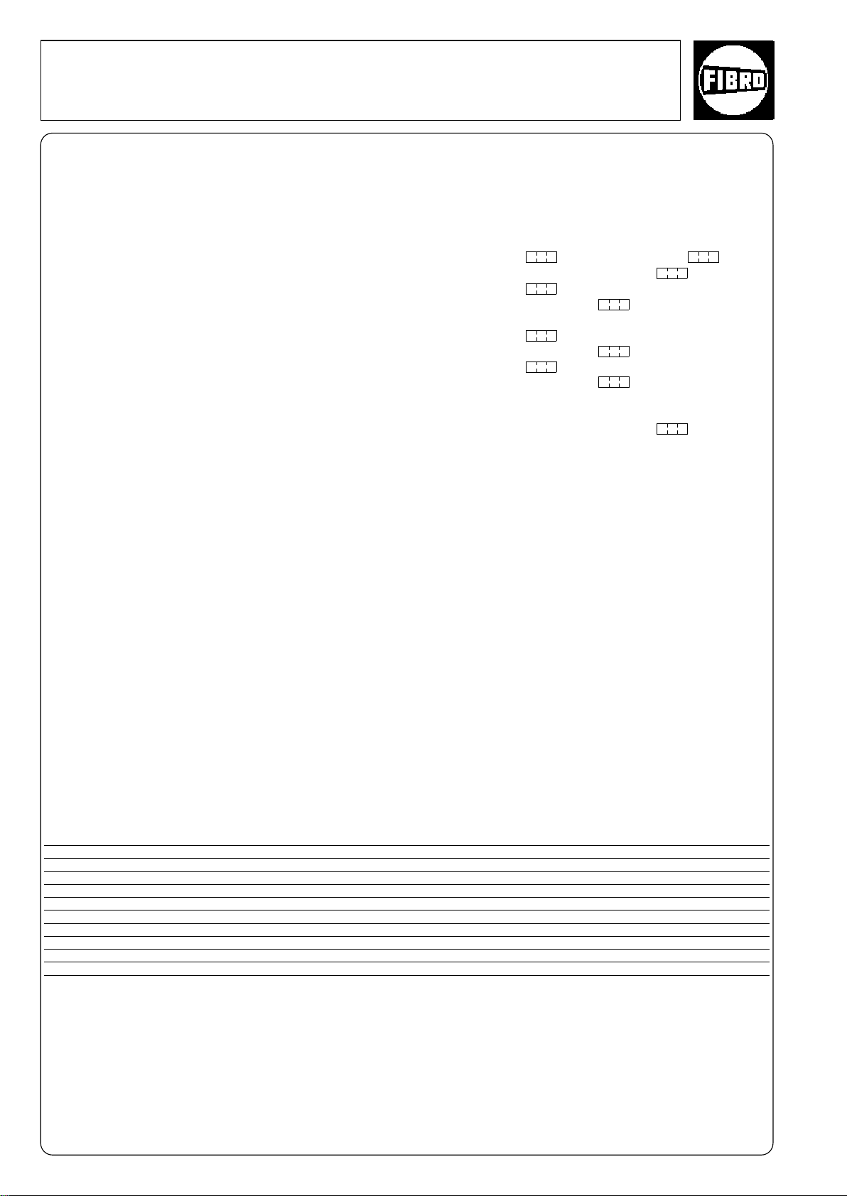
Description Force Cylinders Compact Cams Cams Power Unit
Force (magnitude) kN
Initial restoring force kN
Minimum gas pressure bar
Maximum gas pressure bar
Stroke length mm
Maximum speed m/s
Maximum restoring speed m/s
Maximum frequency Strokes/min.
Ambient temperature °C
* not for 2018.11.01500.
** including +10 mm overtravel
1)
not for 2018.20.01500. and 2018.20.15000.
Table 1: Technical data
2018.30. 2018.11. 2018.12. 2018.20.
15 40 60 90 150 15 40 60 90 150 40 15 40 60 90 150
25813212 4710154 –––––
10 125 105 125 50
40 180 150 180 180
25, 50, 100 24, 49, 99* 49 35**, 60**, 110**, 160**
0,8 0,8 0,8 0,8
0,8 0,8 0,8 0,8
30 60 30 60 60 60 30 30
10–40 10–40 10-40 10–40
Flange
Values other than those specified in the above table
may be accepted under certain circumstances or if
different stroke lengths, speeds and frequencies are
combined.
8
(1)
°
2·14188·2000·1
subject to alterations
Page 9
2018. Flex Cam
121722
160
140
120
100
80
180
60
40
20
0
2732374247525758534843383328231813
2
70
830
2
3
4
1
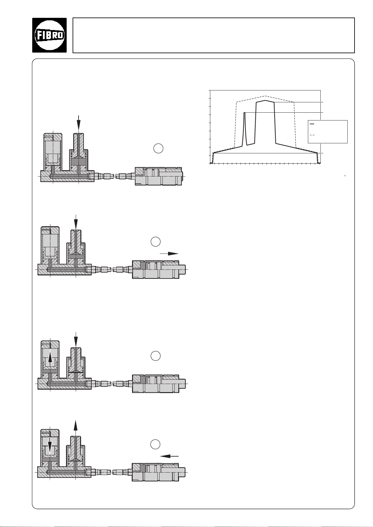
Function
The individual components of the Flex Cam system
described above interact as follows:
The Power Cylinder is actuated by the stroke of the
press.
P
= 0
Oil
Once the pressure build-up in the Flex Cam
exceeds the preset pressure in the Force Cylinder, the
Force Cylinder extends.
P
= P
= P
Work
Accum.
+ P
Retract
Oil
When the Force Cylinder reaches its working
position, the pressure in the system rises to match the
pressure in the Accumulator. The rest of the displaced
volume of oil is then held in the Accumulator (Power
Cylinder overtravels by approx. 3 - 10 mm).
P
Oil
Pressure ratios in the system
P
Accumulator
P
+ P
Work
Retract
Normal
working stroke
Blocking
Oil pressure [bar]
Travel [mm]
The above diagram shows the oil pressure build-up
during the work cycle. Before the working motion, the
oil-system is pressureless. When the Power Cylinder is
actuated, the oil pressure rises to the preset gas pressure in the Cam Unit. As the Force Cylinder continues to
travel, the volume of gas is further compressed until the
work operation is executed. At the same time, the backpressure in the system rises due to the punching
operation, for example. Once the operation has ended,
the Power Cylinder continues as far as the end position
of the Force Cylinder. This ensures that the excess
volume of oil is fully absorbed by the Accumulator. At
the same time, the oil pressure rises to match the
charging pressure in the Accumulator.
If a malfunction occurs in the tool part during system
travel and blocks the travel of the Cam Unit, all the
displaced oil is held in the Accumulator. The oil pressure
increases until it equals that of the compressed nitrogen in the Accumulator.
The system is protected by an integral rupture protection device in the Accumulator which opens at 517 bar
to vent the nitrogen. The resulting system security
protects the tool from damage by the Flex Cam.
slide
P
Retract
This overtravel is essential since it ensures that a
constant contact pressure is built up during each stroke.
P
= P
Oil
Accum. + PRetract
°
2·14181·2000·1
subject to alterations
At the same time the pressure on the Power Cylinder
is relieved (return travel of the press), the Force
Cylinder is reset by the nitrogen gas.
9
Page 10
Flex Cam 2018.
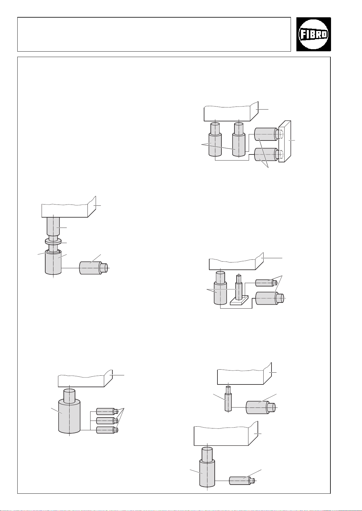
Possible combinations
Power Unit with Cam Unit
Cam Unit leading
If a stroke of the Cam Unit is required before the tool
actually reaches its working position, this can be
achieved by incorporating a gas spring. The press stroke actuates a gas spring which, in turn, actuates the
Power Unit, since its prestressing force is higher than
the nominal force of the Power Unit.
When the Cam Unit reaches its end position, the drive
(press) overtravel is compensated by the retracting
piston rod of the gas spring. A spring contact washer
transmits the pressure of the gas spring to the supporting tube when the Power Unit reaches its end position.
Press
Gas spring
Spring contact washer
Power
Cylinder
Supporting
tube
Cam Unit
Several Cam Units driven synchronously
Synchronous operation can be achieved by using two
systems of the same dimensions, although this application requires the restoring force of the individual
Cam Units to be equal, as well.
Press
Power
Unit
Cam Unit
Slide
One or more Cam Units driven with delay
A time delay, and thus a variable working sequence for
the Cam Units, can be achieved by combining two
different strokes. The first Power Unit to be actuated
executes the first step. As the Cam Unit moves beyond
its end position, the excess oil is displaced into the
Accumulator (not shown in the diagram). The second
Power Unit can then enter the working sequence as
required.
Press
°
„leading“
°
Several Cam Units driven asynchronously
Several Cam Units can be driven by a common Power
Unit. The individual Cam Units should not, however, be
mechanically connected to one another since the
feedrates cannot be totally synchronised due to the
different connection lengths (system losses) and
restoring forces.
Press
Power
Unit
Cam Unit
Cam Unit
Power
Unit
Variable speed / force drive
The forces or travel speeds can be combined as
required by varying the ratio between Power Unit sizes
and Cam Unit sizes. The maximum travelling speed
should not exceed 0.8 m/s, however.
Press
Power
Unit
°
Cam Unit
Press
°
°
10
Power
Unit
Cam Unit
°
°
2·14182·2000·1
subject to alterations
Page 11
2018. Flex Cam
Transmission ratios in use
Transmission or reduction ratios can be expressed in
four different ways:
a) Force
b) Speeds of the individual Cam Units
c) Press travel speed to Cam Unit travel speed
d) Stroke lengths
Transmission ratios
The nominal transmission ratio of 1:1 is normally used
throughout the system.
The ratio can vary, however, according to the combination (and number) of Power Units and Cam Units
used (see table on page 10).
Selecting the components
The component sizes are explained step by step
below with regard to the forces required, stroke length
and the number of operations.
Step 1: Size of the Cam Unit
Calculate the force required for the operation to be
carried out. The Cam Unit used should provide sufficient force to execute the operation. If the force required cannot be precisely calculated, we recommend
that you use a larger Cam Unit.
Step 3: Order number of the Cam Unit
Select the Cam Unit according to the type of
operation to be performed. See also pages 8,10-12
Compact Cam: 2018.11. .
Flange Cam: 2018.12.04000.049
Force Cylinder: 2018.30. .
Example: The order number for the Compact Cam is
2018.11.04000.049
Force required (kN) Cam Unit
0– 15 2018. .01500.
15– 40 2018. .04000.
40– 60 2018. .06000.
60– 90 2018. .09000.
90–150 2018. .15000.
Force required:
Example: If the force required is 22 kN, then a 40 kN Cam Unit
should be used. Cam Unit 2018. .04000.
kN Cam Unit size:
Step 2: Cam Unit stroke length
Determine the Cam Unit stroke required to execute the
operation in the tool. Use the Cam Unit with the shortest possible stroke, but remember that the tool must
have sufficient space for the workpiece.
Required stroke Max. stroke length
length (mm) of Cam Unit (mm) Part number
0– 25 25 (24)*** 2018. . .025*
25– 50 50 (49)*** 2018. . .050*
50–100 100 (99)**/*** 2018. . .100*
*) 2018.11. .024/049/099
**) This stroke length does not apply to Compact Cam
2018.11.01500.
***) Compact cam
Stroke length of Cam Unit: mm
Example: If the stroke length required is 35 mm, use a Cam Unit
with a stroke length of 50 mm.
°
2·14183·2000·1
subject to alterations
11
Page 12
Flex Cam 2018.
Step 4a
Size and stroke of the Power Unit
Follow step 4a if one to three Cam Units of the same
size are connected to a given Power Unit. If different
Cam Units are connected to a Power Unit, then step
4b should be used.
Select the Power Unit from the following table. The
table should be read in the following order: Cam Unit –
force – stroke – number – Power Unit – stroke length.
We recommend that no more than three Cam Units be
connected to a single Power Unit.
Make sure that you do not exceed the maximum Cam
Unit stroke speed (0.8 m/s).
Power unit selection table
Cam Unit Nom. Power Unit
force (kN)
15 25 1 035 35 1,0 035 20 2,5 035 16 4,0 035 14 6,3 035 13 9,8
stroke (mm)
25 2 060 60 0,5 035 30 1,2 035 23 2,0 035 18 3,1 035 15 4,9
25 3 110 85 0,3 060 40 0,8 035 29 1,3 035 22 2,1 035 18 3,3
50 1 060 60 1,0 035 30 2,5 035 23 4,0 035 18 6,3 035 15 9,8
50 2 110 110 0,5 060 50 1,2 035 35 2,0 035 26 3,1 035 20 4,9
50 3 110 70 0,8 060 48 1,3 035 34 2,1 035 25 3,3
No. 15 kN SU TR 40 kN SU TR 60 kN SU TR 90 kN SU TR 150 kN SU TR
Cam Unit Power Unit
04000 50 2 ?
Force Stroke Number
Selection flowchart
Power Unit = Nominal working force / nominal stroke + 10 mm
overtravel
SU = Working stroke (stroke actually used) + 10 mm
TR = Transmission ratio
Stroke
used
100 1 110 110 1,0 060 50 2,5 035 35 4,0 035 26 6,3 035 20 9,8
100 2 110 91 1,2 060 60 2,0 060 42 3,1 035 30 4,9
100 3 160 131 0,8 110 85 1,3 060 58 2,1 060 41 3,3
40 25 1 110 72 0,4 035 35 1,0 035 26 1,6 035 20 2,5 035 16 3,9
60 25 1 110 110 0,3 60 50 0,6 035 35 1,0 035 26 1,6 035 20 2,4
90 25 1 110 73 0,4 060 49 0,6 035 35 1,0 035 26 1,6
25 2 060 60 0,5 060 41 0,8 035 30 1,3 035 23 2,0
25 3 110 85 0,3 060 57 0,5 060 40 0,8 035 29 1,3
50 1 060 60 1,0 060 41 1,6 035 30 2,5 035 23 3,9
50 2 110 110 0,5 110 72 0,8 060 50 1,3 035 35 2,0
50 3 160 160 0,3 110 103 0,5 110 70 0,8 060 48 1,3
100 1 110 110 1,0 110 72 1,6 060 50 2,5 035 35 3,9
100 2 160 134 0,8 110 89 1,3 060 61 2,0
100 3 160 129 0,8 110 86 1,3
25 2 110 91 0,3 060 60 0,5 060 42 0,8 035 30 1,2
25 3 160 131 0,2 110 85 0,3 060 58 0,5 060 41 0,8
50 1 110 91 0,6 060 60 1,0 060 42 1,6 035 30 2,4
50 2 110 110 0,5 110 74 0,8 060 51 1,2
50 3 160 160 0,3 110 106 0,5 110 71 0,8
100 1 110 110 1,0 110 74 1,6 060 51 2,4
100 2 160 138 0,8 110 92 1,2
25 2 160 136 0,2 110 88 0,3 060 60 0,5 060 42 0,8
25 3 160 127 0,2 110 85 0,3 060 58 0,5
50 1 160 136 0,4 110 88 0,6 060 60 1,0 060 42 1,6
50 2 110 110 0,5 110 74 0,8
50 3 160 160 0,3 110 106 0,5
100 1 110 110 1,0 110 74 1,6
150 25 1 110 108 0,3 110 71 0,4 060 49 0,6 035 35 1,0
12
25 2 160 132 0,2 110 88 0,3 060 60 0,5
25 3 160 127 0,2 110 85 0,3
50 1 160 132 0,4 110 88 0,6 060 60 1,0
50 2 110 110 0,5
100 1 110 110 1,0
subject to alterations
°
2·14184·2000·1
Page 13
2018. Flex Cam
See also the following examples:
Example 1 (Fig. 1): A Power Unit 2018.20.04000.060
is provided as standard for a Compact Cam
2018.11.04000.049. The nominal stroke of the Power
Unit is 60 mm. The transmission ratio is 1:1. The stroke
of the Compact Cam is thus performed at the same
speed as the press.
Example 2 (Fig. 2): If a press stroke of just 30 mm
can be used to execute the operation, then a larger
Power Unit 2018.20.09000.035 should be used for the
Cam Unit 2018.11.04000.049. The Power Unit stroke
used is 30 mm, the transmission ratio is 2.5. If the
press speed is 0.3 m/s, then the Cam Unit stroke
speed obtained is 2.5 × 0.3 m/s = 0.75 m/s.
The stroke used by Power Unit and Cam Unit can be
perfectly matched to any special constraints associated with the tool.
For some applications, the speed of the Cam Unit
must be increased in proportion to the press speed.
If several Cam Units are connected to a
Power Unit, then the individual Cam Units
will not have the same stroke speed.
Cam Unit
04000 50 1 60
Fig. 1: Selection for example 1
Cam Unit
04000 50 1 30
Fig. 2: Selection for example 2
Power Unit
2018.20.
04000.060
Power Unit
2018.20.
09000.035
Example 3 (Fig. 3): A Power Unit 2018.20.04000.110
can be used with two Compact Cams
2018.11.04000.049 and a useful press stroke of
110 mm. The Power Unit stroke used is 110 mm and
the transmission ratio is 0.5.
If the press speed is 0.3 m/s, then the mean Cam Unit
stroke speed obtained is 0.5 × 0.3 = 0.15 m/s.
Order number of the Power Unit.
See also pages 19, 23, 27, 31, 35.
°
Cam Unit
04000 50 2 110
Power Unit:
2018.20. .
Fig. 3: Selection for example 3
Power Unit
2018.20.
04000.110
2·14185·2000·1
subject to alterations
13
Page 14
Flex Cam
Step 4b
Size and stroke of the Power Unit
for different Cam Unit sizes
The total volume of oil in the Cam Units should be calculated using the following formula. The total volume
of oil is the sum of all the volumes for all Cam Units.
The volume is the product of the piston surfaces and
strokes used. The total volume of oil VNfor the Power
Units corresponds to the minimum volume of oil for the
Cam Units (in dm3). ANis the piston surface area in the
Cam Unit (dm2) as shown in table 2.
VN= [(A1 s1) + (A2 s2)...(AN sN)] : 100 (Formula 1)
AN= Piston surface area of Cam Units
sN= Stroke length of Cam Units
WK AZ AK 15 kN 40 kN 60 kN 90 kN 150 kN
AN(dm2) 0,13 0,31 0,50 0,79 1,23
Tab. 2: Piston surface area of Cam Units
Total volume of oil of Cam Units: VN= dm
WK = Compact Cam 2018.11. .
AZ = Force Cylinder 2018.30. .
AK = Flange Cams 2018.12. .
3
The volume of oil of the selected Power Unit should
be greater than 0,189 dm
3.
For example, the
2018.20.06000.060 supplies 0,251 dm3.
(The 2018.20.04000.110 could also be used)
(see table 3)
Calculate the used stroke of the Power Unit:
s
= ((VN: VG) sG)+ 10
Gerf
s
= ((0,189 : 0,251) 50) + 10 (see formula 2)
Gerf
= 48 mm
s
Gerf
In the above example, we recommend a Power Unit
2018.20.06000.060 with a used stroke of 48 mm. The
admissible Cam Unit stroke speeds defined in section
9 must not be exceeded. It should also be noted that
the Cam Units will have different stroke speeds if two
Cam Units are driven by a single Power Unit.
Step 5
Select appropriate hoses and screwed couplings. The
maximum admissible hose length between Power Unit
and the Cam Unit is 2000 mm. The nominal hose diameter is determined on the basis of the size of the
Power Unit. The hose size is matched to the flow of oil
(see page 48).
Select the appropriate Power Unit from Table 3.
The Power Unit must supply the minimum volume of
oil as calculated above. Calculate the required Power
Unit stroke s
= [(VN:VG) sG] + 10 (Formula 2)
s
Gerf
using the following formula:
Gerf
VN=Total volume of oil of Cam Units
VG=Total volume of oil of Power Unit
sG= Power Unit stroke
s
= Power Unit stroke required
Gerf
Stroke Nominal Power Unit size 2018.20.
length stroke length sG15 kN 40 kN 60 kN 90 kN 150 kN
.035 25 0,031 0,078 0,126 0,196 0,307
.060 50 0,063 0,156 0,251 0,393 0,614
.110 100 0,126 0,312 0,502 0,785 1,227
.160 150 0,188 0,468 0,753 1,178 1,841
Tab. 3: Volume of oil of Power Unit V
Power Unit stroke used: s
= mm
Gerf
G
(dm3)
Example:
Select a Power Unit to operate a Compact Cam
2018.11.01500.049 and a Force Cylinder
2018.30.04000.050 with a used working stroke of just
40 mm.
V
= [(AWK sWK) + (AAZ sAZ)] : 100
N
= [(0,13 49) + (0,31 40)] : 100 (see formula 1)
V
N
VN= 0,189
Depending on the press speed a nominal hose width
smaller than the standard nominal width may be used
(see table 4).
Nominal hose size Press speed
Standard nominal
Power Unit 0,8 m/s 0,6 m/s 0,4 m/s 0,2 m/s
2018.20.01500 DN 12 DN 12 DN 12 DN 12
2018.20.04000 DN 20 DN 20 DN 12 DN 12
2018.20.06000 DN 25 DN 20 DN 20 DN 12
2018.20.09000 DN 25 DN 25 DN 20 DN 12
2018.20.15000 DN 32 DN 32 DN 25 DN 20
Ta ble 4: Press speed/nominal hose size
width Max. speed
It is easiest to determine the correct hose
➭
length if both Power Unit and Cam Unit are
installed inside the tool.
Remember to protect the hose against sharp edges
etc. The hose moves slightly during operation due to
the pulsating oil pressure.
Observe the minimum bending radius.
°
14
2·14186·2000·1
subject to alterations
Page 15

Flex Cam
Dimensions and Order No.
Cam Units
Force Cylinders
Compact Cam
Flange Cam
Power Units
°
2·14189·2000·1
15
Page 16
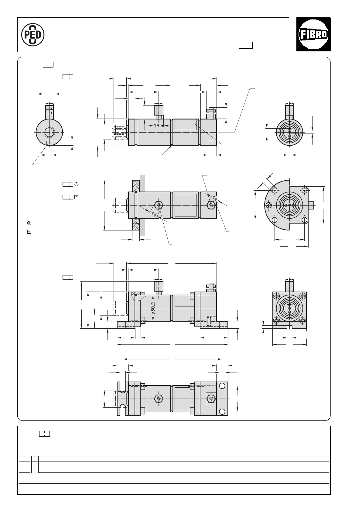
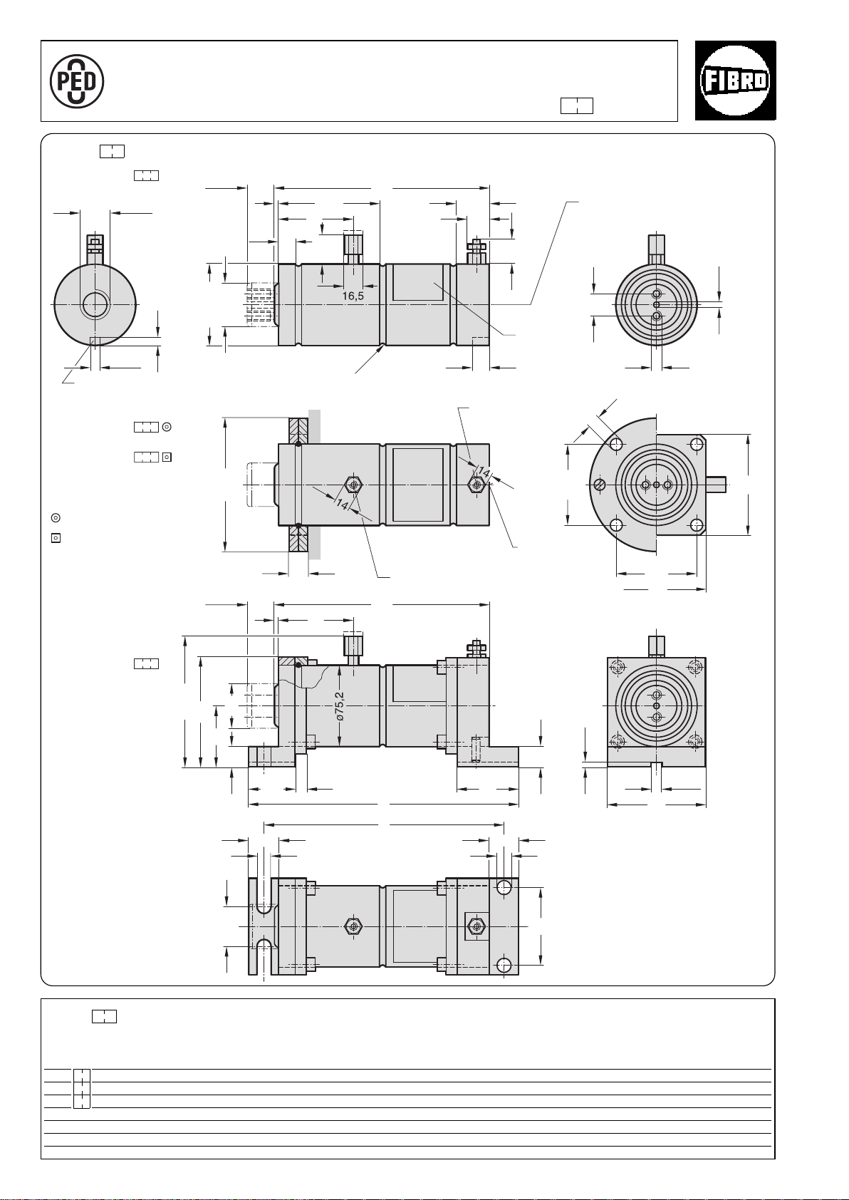
Force Cylinder 15 kN 2018. .01500.
A
P
P
R
O
V
E
D
9
7
/
2
3
/
E
C
ø11
ø4
12
ø9
34,5
43
2222
33
+0,1
10
65
±0,1
4
l
min
58
13
a
5311
89*
70
13
ø25
56,5
56,5
70
13
3)
ø95
17
M6
31
19
31
l
min
1
/
2
G
+0,2
10
12,5
3
81,5
58
26*
ø50,2
±0,1
ø25
8
R2
+0,2
70
38
3
b
2018.30.01500.
2018.50.01500.
2018.60.01500.
2480.055.00750
2480.057.00750
2018.40.01500.
16
2018. .01500.
Torsion protection groove
Spare parts
Mounting flanges
Stroke
Stroke
2)
Hydraulic connection G
1
/2
Rating plate
Bleeder valve
Hydraulic
Nitrogen gas
connection
1)
connection G1/2
Stroke
Stroke
2)
Stroke
Spare parts
Mounting flanges
On the piston rod
2480.045.00750
On the hydraulic
connector
2480.046.00750
* +4,5 mm with sealing stopper
2018. .01500.
Stroke
1)
2)
3)
Restoring force in kN*
at 20 bar
Force Cylinder (max. 40 bar)
Order no Stroke l min abStroke start Stroke end
2018. .01500.025 25 173 214 192 1,5 3,1
2018. .01500.050 50 223 264 242 1,5 3,1
2018. .01500.100 100 323 364 342 1,5 3,1
16
* isothermic
Nitrogen gas connector: caution – before
removing the connector check that the
cylinder has no gas pressure.
Stroke length: Important – the nominal
stroke length must be maintained from
the very start by means of an external
stop.
The unused residual stroke is required as
a compression chamber for the nitrogen
gas, if the gas pressure will increase and
may cause damage.
This fastening may only be subjected to
pressure (by support).
subject to alterations
°
2·14190·2000· 1
Page 17

°
2·14191·2000· 1
subject to alterations
17
Page 18
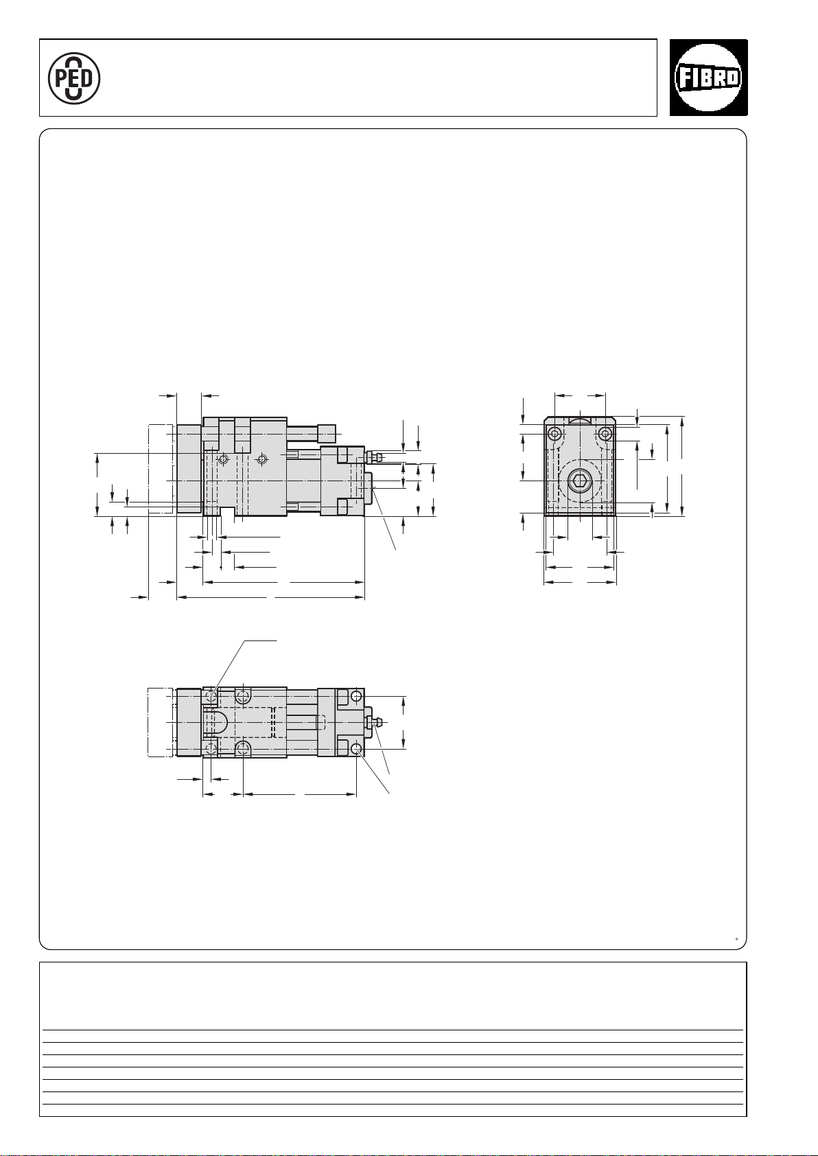
Compact Cam 15 kN 2018.11.01500.
ø40
11
ø7,5
21
±0,015
44
±0,015
7,5
52
7
12
20
44
29
l
1
+0,02
ø8
14
+0,02
12
22
(2x)
l
6,5
44
33
e
ø11(2x)
73
82
7,5
26,5
42
ø20
59
56
1)
A
P
P
R
O
V
E
D
9
7
/
2
3
/
E
C
2018.11.01500.
Hydraulic connection
1
/2
G
Max.
stroke
Locating pin 8 (2x)
Venting M10x1
M8 fixing screw (4x)
Note:
1)
The punch should preferably be mounted
in the middle of the piston rod.
It can also be located in the shaded area
if necessary.
A guide bolster with external guide to
absorb the lateral forces should be
provided for coping and cutting
operations.
2018.11.01500.
Compact Cam Max. at 180 bar
Restoring force in kN
Order No stroke e l l1 Stroke start Stroke end
2018.11.01500.024 24 94 155,5 133,5 2 2,6
049 49 119 180,5 158,5 2 2,6
18
°
2·14192·2001· 2
subject to alterations
Page 19
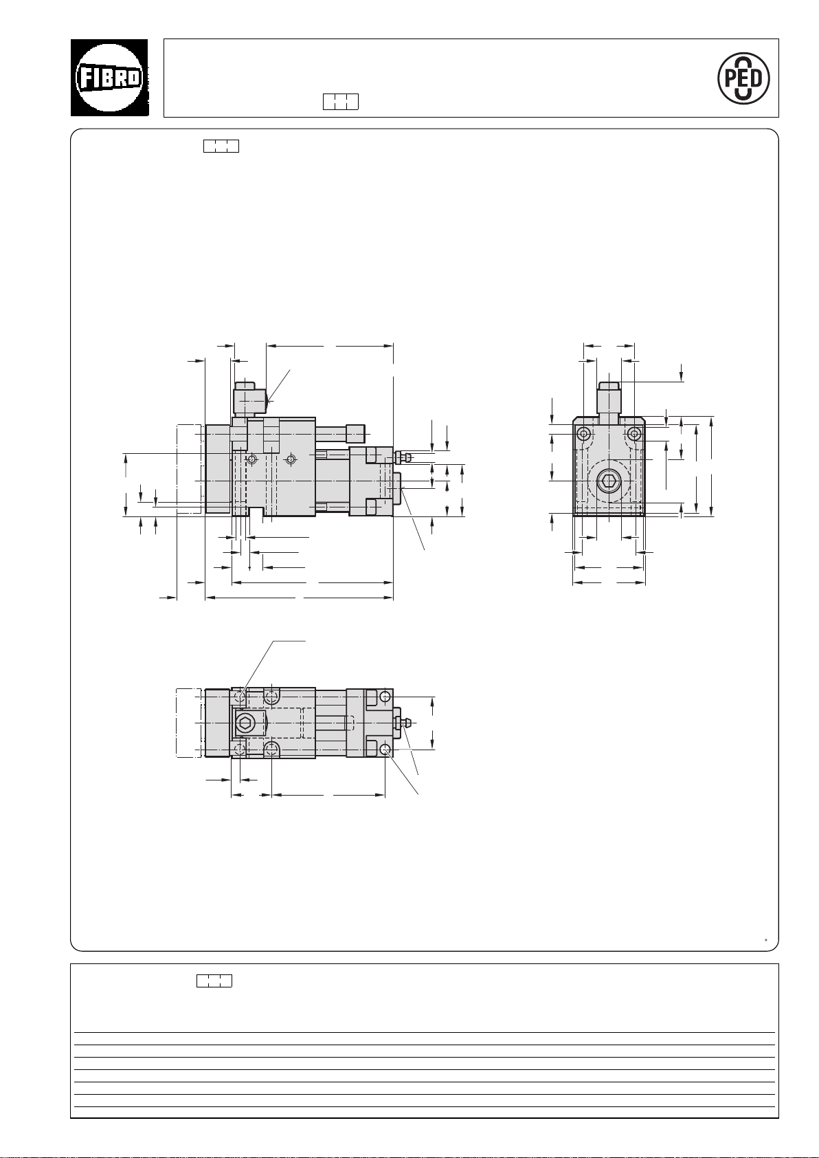
44
ø40
1)
28,5
19,5
25
20
±0,015
7,5
l
1
+0,02
ø8
14
+0,02
12
22
(2x)
l
52
7
12
11
ø7,5
21
29
l
2
±0,015
44
ø20
59
56
ø11(2x)
73
82
7,5
26,5
6,5
33
e
44
42
Compact Cam 15 kN
A
P
P
R
O
V
E
D
9
7
/
2
3
/
E
C
2018.11.01500. .1 with gas monitoring connection
2018.11.01500. .1
Install together with measuring hose and control fitting (gas spring and nitrogen connection are valveless).
Nitrogen gas connection
G1/8
Hydraulic connection
1
G
/2
Max.
stroke
Locating pin 8 (2x)
Venting M10x1
M8 fixing screw (4x)
Note:
1)
The punch should preferably be mounted
in the middle of the piston rod.
It can also be located in the shaded area
if necessary.
A guide bolster with external guide to
absorb the lateral forces should be
provided for coping and cutting
operations.
2018.11.01500. .1
Restoring force in kN
Compact Cam max. at 180 bar
Order No stroke e l l1 l2 Stroke start Stroke end
2018.11.01500.024.1 24 94 155,5 133,5 107 2 2,6
2018.11.01500.049.1 49 119 180,5 158,5 132 2 2,6
°
2·16267·2005·2
subject to alterations
19
Page 20
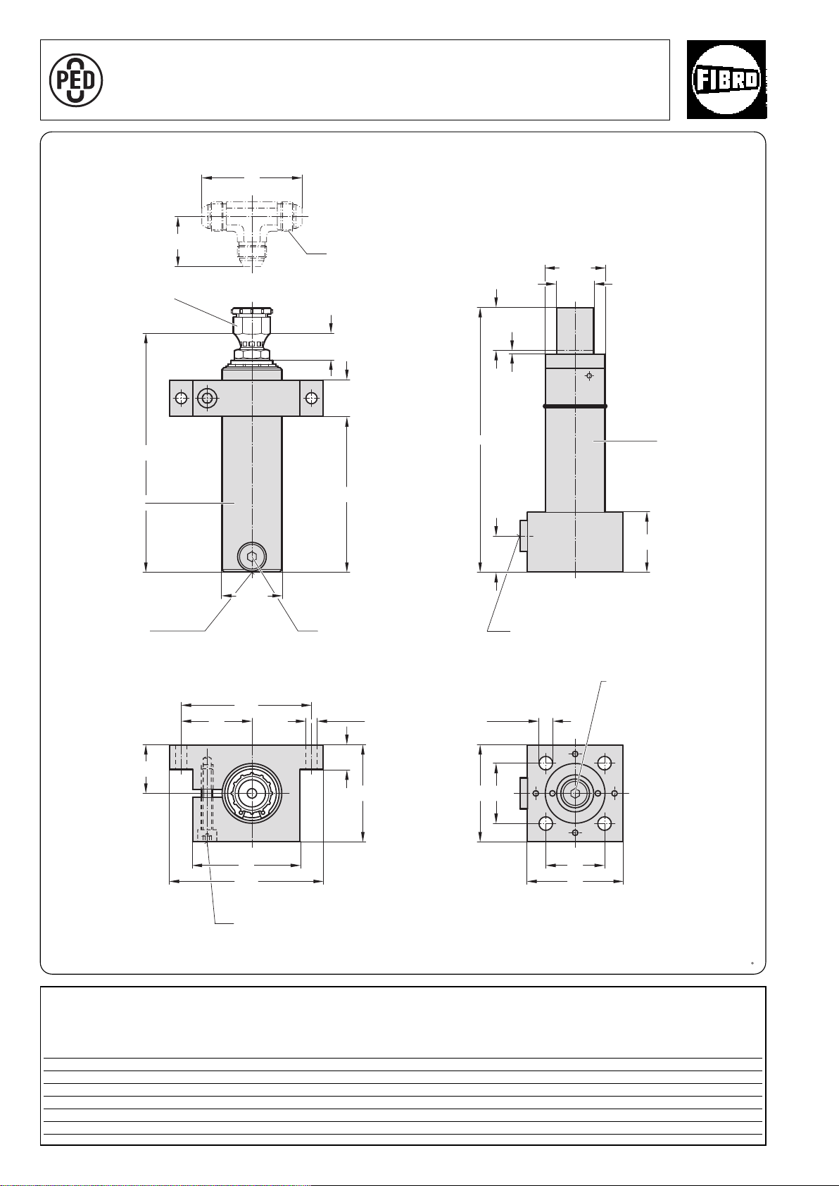
Power Unit 15 kN
42
84
24
30
2
l
1
l
ø50,1
50
30
l
ø32
ø50,1
3
40
20
80
90
130
ø9 (x2)
60
110
ø11 (x4)
50
80
80
50
A
P
P
R
O
V
E
D
9
7
/
2
3
/
E
C
with separate Accumulator 2018.25.01500.
2018.25.01500.
Hydraulic connection
1,5
JIC
/16"-12
Accumulator
Rupture protection
device
Nominal hose size G
Nitrogen gas
connection G
1
/2
1)
Stroke
Power Cylinder
1
/8
Hydraulic connection G
1
/2
Hydraulic filling opening G
1
/4
* Tighten M8 fixing screw to 25 Nm
Fixing screw
1)
The overtravel compensation is the nominal stroke + 10 mm additional stroke.
2018.25.01500.
Power Unit stroke
Order No +10
1)
ll1l
2018.25.01500.035 35 220 201 130
2018.20.01500.060 60 270 251 180
2018.20.01500.110 110 370 351 280
20
2
°
2·16272·2001· 1
subject to alterations
Page 21
ø11
30
3
c
l
50
80
50
80
130
160
ø32
2018.20.01500. Power Unit 15 kN
2018.20.01500.
Nitrogen gas connection G
Rating plate
O
R
V
P
E
D
P
A
9
C
7
/
E
/
2
3
1
/8
1)
Stroke
Accumulator
Adapter plate
M12 for lifter stud
(2x)
Rupture protection device
Power Cylinder
1
Hydraulic filling opening G
/4
Hydraulic connection G1/2
1)
The overtravel compensation is the nominal stroke + 10 mm additional stroke.
2018.20.01500.
Power Unit Stroke
Order No. c l +10
2018.20.01500.035 185 220 35
2018.20.01500.060 210 270 60
2018.20.01500.110 260 370 110
°
2·14193·2001· 2
subject to alterations
1)
21
Page 22
Force Cylinder 40 kN 2018. .04000.
A
P
P
R
O
V
E
D
9
7
/
2
3
/
E
C
15 ø13
ø11
16
b
2628
64
37
90
68
120,5*
101
57
ø36
19
56
a
43,5
73,5
90
73,5
3)
ø122
M8
20
8
30
19
3
68
31
R2,5
ø36
3
/
4
G
+0,2
10
2018.30.04000.
2018.50.04000.
2018.60.04000.
2480.055.01500
2480.057.01500
2018.40.04000.
l
min
15,5
26*
ø75,2
±0,1
+0,2
ø4
92,5
16
90
10
19
3
l
min
+0,1
10
4
±0,1
2018. .04000.
Torsion protection groove
Spare parts
Mounting flanges
Stroke
Stroke
2)
3
Hydraulic connection G
/
4
Rating plate
Stroke
Stroke
Nitrogen gas
connection
Stroke
2)
Bleeder valve
1)
Hydraulic
connection G
3
/
4
Stroke
Spare parts
Mounting flanges
On the piston rod
2480.045.01500
On the hydraulic
connector
2480.046.01500
* +4,5 mm with sealing stopper
2018. .04000.
Force Cylinder (max. 40 bar)
Order no Stroke l
2018. .04000.025 25 195 246 219 4,2 8,4
min
abStroke start Stroke end
Restoring force in kN*
2018. .04000.050 50 245 296 269 4,2 8,4
2018. .04000.100 100 345 396 369 4,2 8,4
22
1)
Nitrogen gas connector: caution – before
removing the connector check that the
cylinder has no gas pressure.
2)
Stroke length: Important – the nominal
stroke length must be maintained from the
very start by means of an external stop.
The unused residual stroke is required as a
compression chamber for the nitrogen
gas, if the gas pressure will increase and
may cause damage.
3)
This fastening may only be subjected to
pressure (by support).
at 20 bar
* isothermic
subject to alterations
°
°
2·14194·2000· 1
Page 23

°
2·14195·2001· 2
subject to alterations
23
Page 24
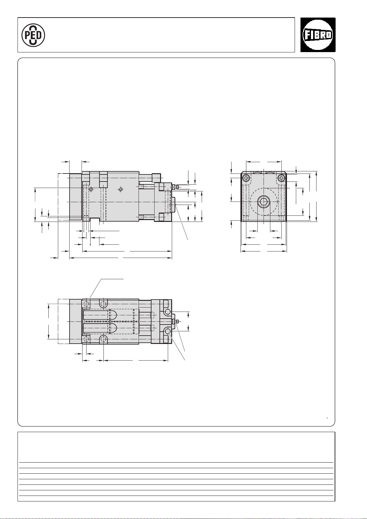
Compact Cam 40 kN 2018.11.04000.
A
P
P
R
O
V
E
D
9
7
/
2
3
/
E
C
ø60
1)
11
ø7,5
37
ø26
16
±0,015
8
+0,02
(2x)
25
71
12
7
ø10
+0,02
20
l
1
l
27
63
41
74
8
e
44
41
105
97,5
ø15(2x)
9,5
38,5
74
±0,015
74
92
95
2018.11.04000.
stroke
Max.
Hydraulic connection
3
/4
G
Locating pin 10 (2x)
Venting M10x1
M10 fixing screw (4x)
Note:
1)
The punch should preferably be mounted
in the middle of the piston rod.
It can also be located in the shaded area
if necessary.
A guide bolster with external guide to
absorb the lateral forces should be
provided for coping and cutting
operations.
2018.11.04000.
Compact Cam Max. at 180 bar
Order No stroke e l l1 Stroke start Stroke end
2018.11.04000.024 24 135 214 187 4 5,2
049 49 160 239 212 4 5,4
099 99 210 289 262 4 5,6
24
Restoring force in kN
°
2·14196·2000·0
subject to alterations
Page 25
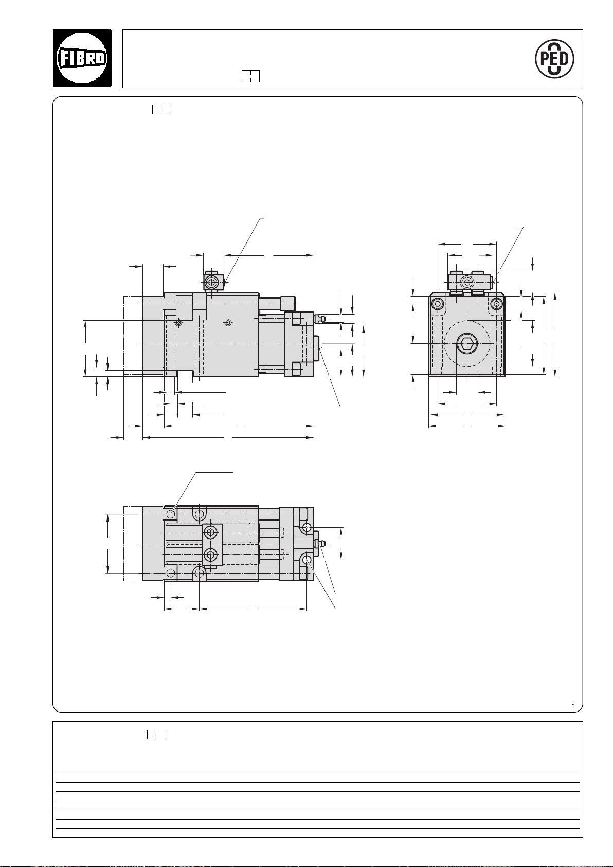
ø60
1)
56,5
28,5
41
l
2
25
71
12
7
16
±0,015
8
+0,02
(2x)ø10
+0,02
20
l
1
l
27
11
ø7,5
37
41
25
74
8
e
44
ø26
±0,015
74
92
95
9,5
38,5
105
97,5
ø15(2x)
74
63
Compact Cam 40 kN
A
P
P
R
O
V
E
D
9
7
/
2
3
/
E
C
2018.11.04000. .1 with gas monitoring connection
2018.11.04000. .1
Install together with measuring hose and control fitting (gas spring and nitrogen connection are valveless).
Duplicate nitrogen gas ports for connecting the measuring hose.
Use only one port whilst keeping the other one closed.
Nitrogen gas connection
G1/8
Additional nitrogen gas
port G1/8
Hydraulic connection
3
/4
G
Max.
stroke
Locating pin 10 (2x)
Venting M10x1
M10 fixing screw (4x)
1)
Note:
The punch should preferably be mounted
in the middle of the piston rod.
It can also be located in the shaded area if
necessary.
A guide bolster with external guide to
absorb the lateral forces should be
provided for coping and cutting operations.
2018.11.04000. .1
Compact Cam max. at 180 bar
Order No stroke e l l1 l2 Stroke start Stroke end
2018.11.04000.024.1 24 135 214 187 112 4 5,2
2018.11.04000.049.1 49 160 239 212 162 4 5,2
2018.11.04000.099.1 99 210 289 262 237 4 5,2
°
2·16277·2001· 1
subject to alterations
Restoring force in kN
25
Page 26
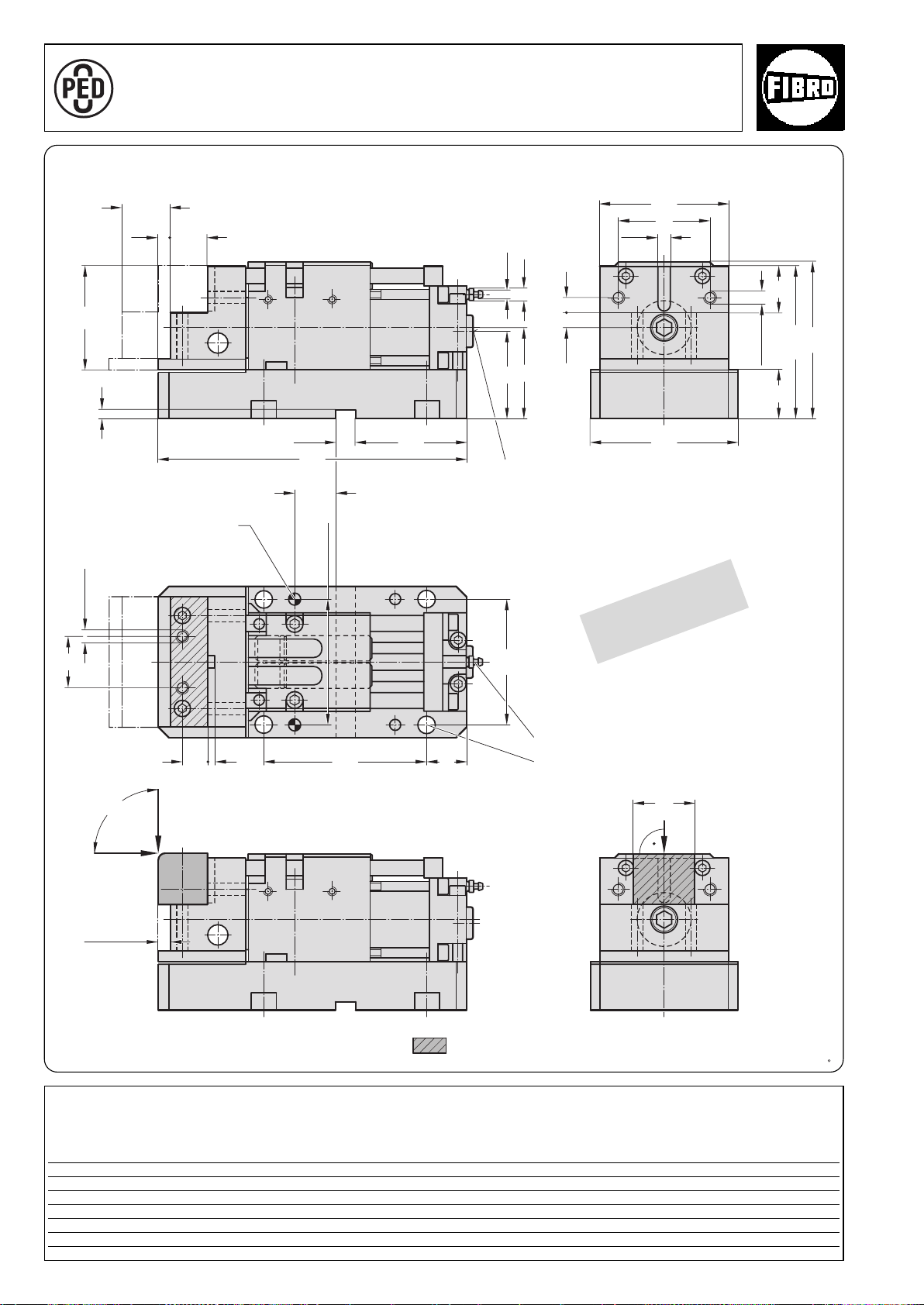
Flange Cam 40 kN 2018.12.04000.049
A
P
P
R
O
V
E
D
9
7
/
2
3
/
E
C
48
90°
F
39
+0,015
120
-0,015
M12 (2x)
45
153
148,5
14,5 15
85
89
11
ø7,5
7
100
120
50
3925 160
145
125
90
13
37
+0,02
20
109
304
M12 (2x)
+0,015
-0,015
F
60
F
+0,02
12
7
2018.12.04000.049
max.
stroke
Locating pin 10 (2x)
Hydraulic connection
3
/4
G
Patented
Maximum
projection
shaping
cheeks
13 mm
Note:
Maximum load application F by flanging operation within
this area:
2018.12.04000.049
Order No stroke Stroke start Stroke end
max. at 180 bar
2018.12.04000.049 49 4 5,2
Restoring force in kN
Venting M10x1
M16 fixing screw (4x)
°
2·16864·2005·2
26
subject to alterations
Page 27
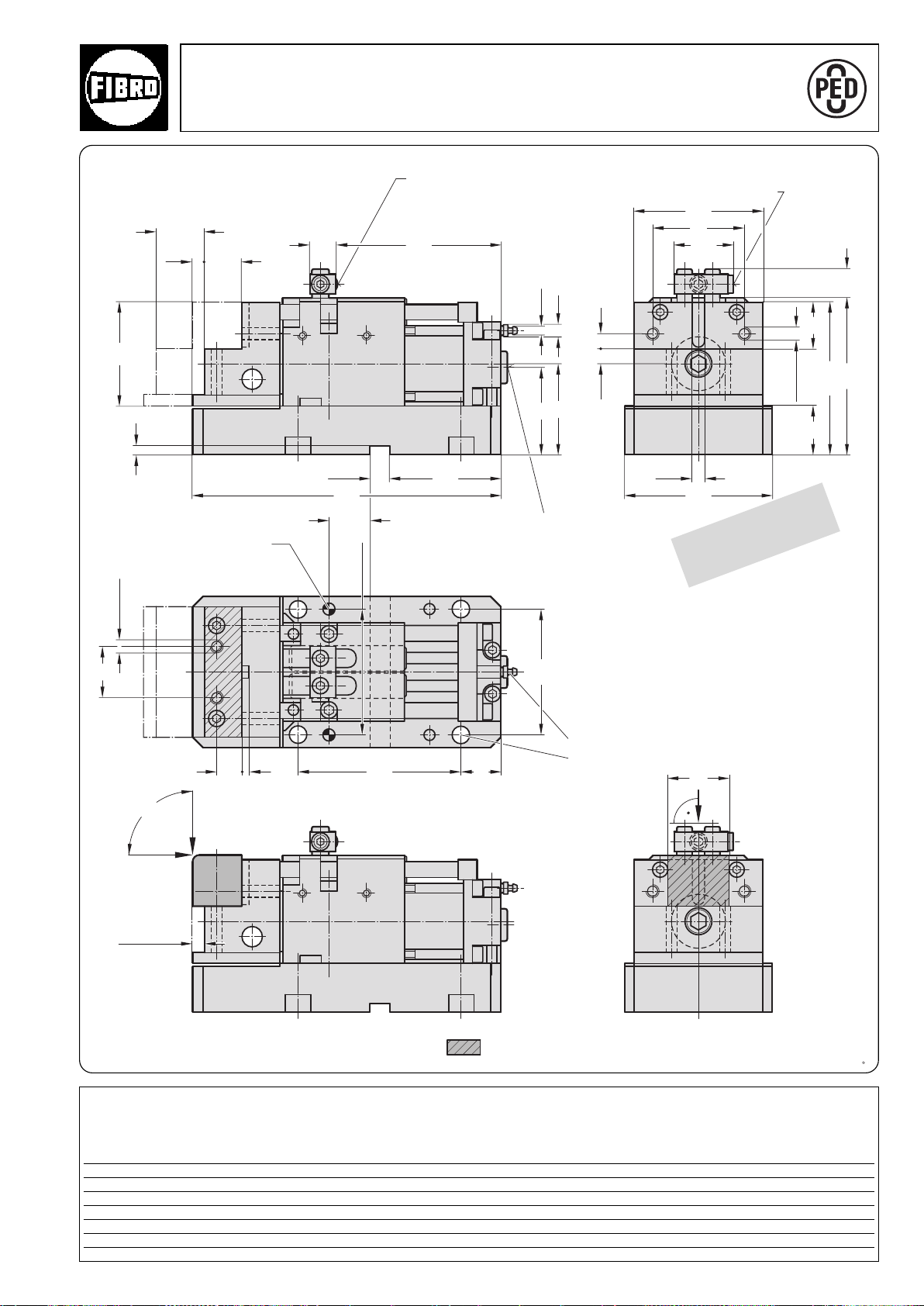
Flange Cam 40 kN
A
P
P
R
O
V
E
D
9
7
/
2
3
/
E
C
48
39
+0,015
120
-0,015
28,5
M12 (2x)
45
153
148,5
14,5 15
85
89
11
ø7,5
7
100
120
50
3925 160
145
125
90
56,5
13
37
+0,02
20
109
304
16225
M12 (2x)
+0,015
-0,015
90°
F
F
60
F
7
+0,02
12
2018.12.04000.049.1 With gas monitoring connection
2018.12.04000.049.1
max.
stroke
Locating pin 10 (2x)
Nitrogen gas
connection G 1/8
Additional nitrogen gas
1
/8
port G
Hydraulic connection
G3/4
Patented
Install together with measuring hose and control
fitting (gas spring and nitrogen connection are
valveless).
Duplicate nitrogen gas ports for connecting the
measuring hose.
Use only one port, whilst keeping the other one
closed.
Venting M10x1
M16 fixing screw (4x)
Maximum
projection
shaping
cheeks
13 mm
Note:
Maximum load application F by flanging operations within
this area:
2018.12.04000.049.1
Order No stroke Stroke start Stroke end
max. at 180 bar
2018.12.04000.049.1 49 4 5,2
°
2·16869·2005·2
subject to alterations
Restoring force in kN
27
Page 28
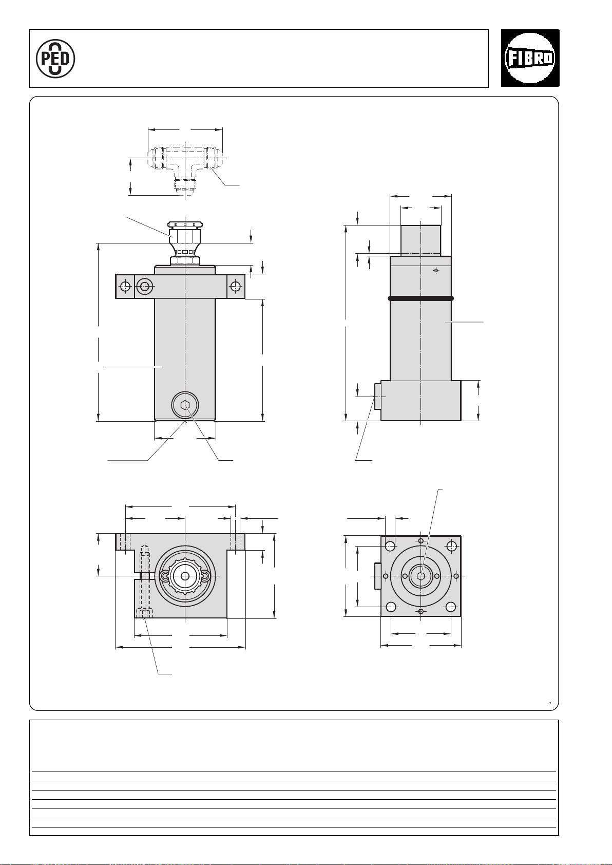
Power Unit 40 kN
ø11 (x4)
46
92
27
30
2
l
1
l
ø75,1
52,5
20
105
115
160
ø11 (x2)
73,5
137
50
30
l
ø50
ø75,1
3
75
100
100
75
A
P
P
R
O
V
E
D
9
7
/
2
3
/
E
C
with separate Accumulator 2018.25.04000.
2018.25.04000.
Hydraulic connection
1,5
/16"-12
JIC
Accumulator
Nominal hose size G3/4
1)
Stroke
Power Cylinder
Rupture protection
device
* Tighten M8 fixing screw to 25 Nm
Fixing screw
Nitrogen gas
connection G
1
/8
Hydraulic connection G3/4
Hydraulic filling opening G
1)
The overtravel compensation is the nominal stroke + 10 mm additional stroke.
1
/4
2018.25.04000.
Power Unit
Order No stroke+10
1)
ll1l
2018.25.04000.035 35 242 219 152
2018.20.01500.060 60 292 269 202
2018.20.01500.110 110 392 369 302
2018.20.01500.160 160 492 469 402
28
2
°
2·16282· 2001·1
subject to alterations
Page 29
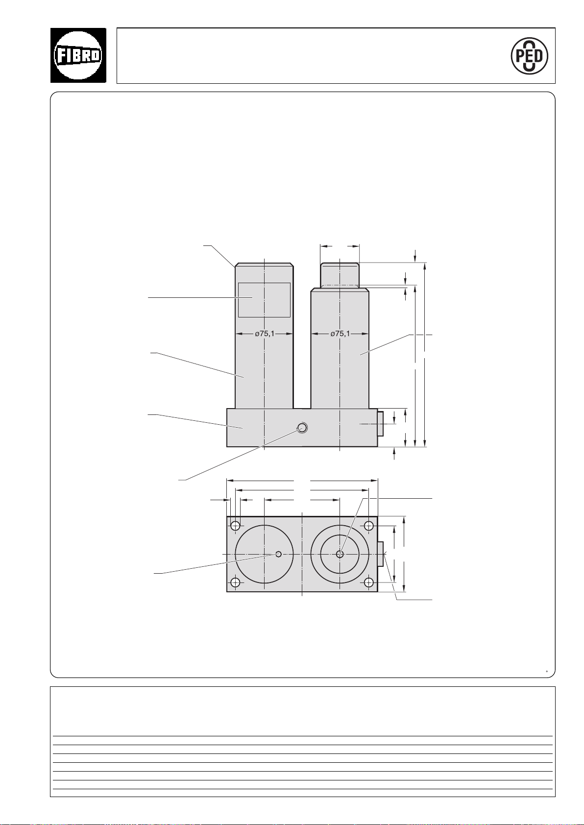
30
175
200
100
ø50
100
75
3
l
c
50
ø11
2018.20.04000. Power Unit 40 kN
A
P
P
R
O
V
E
D
9
7
/
2
3
/
E
C
2018.20.04000.
Nitrogen gas connection G
Rating plate
Accumulator
Adapter plate
M12 for lifter stud
(2x)
1
/8
1)
Stroke
Power Cylinder
1
Hydraulic filling opening G
/4
Rupture protection device
Hydraulic connection G3/4
1)
The overtravel compensation is the nominal stroke + 10 mm additional stroke.
2018.20.04000.
Power Unit Stroke
Order No. c l +10
1)
2018.20.04000.035 207 242 35
2018.20.04000.060 232 292 60
2018.20.04000.110 282 392 110
°
2018.20.04000.160 332 492 160
2·14197·2001·2
subject to alterations
29
Page 30
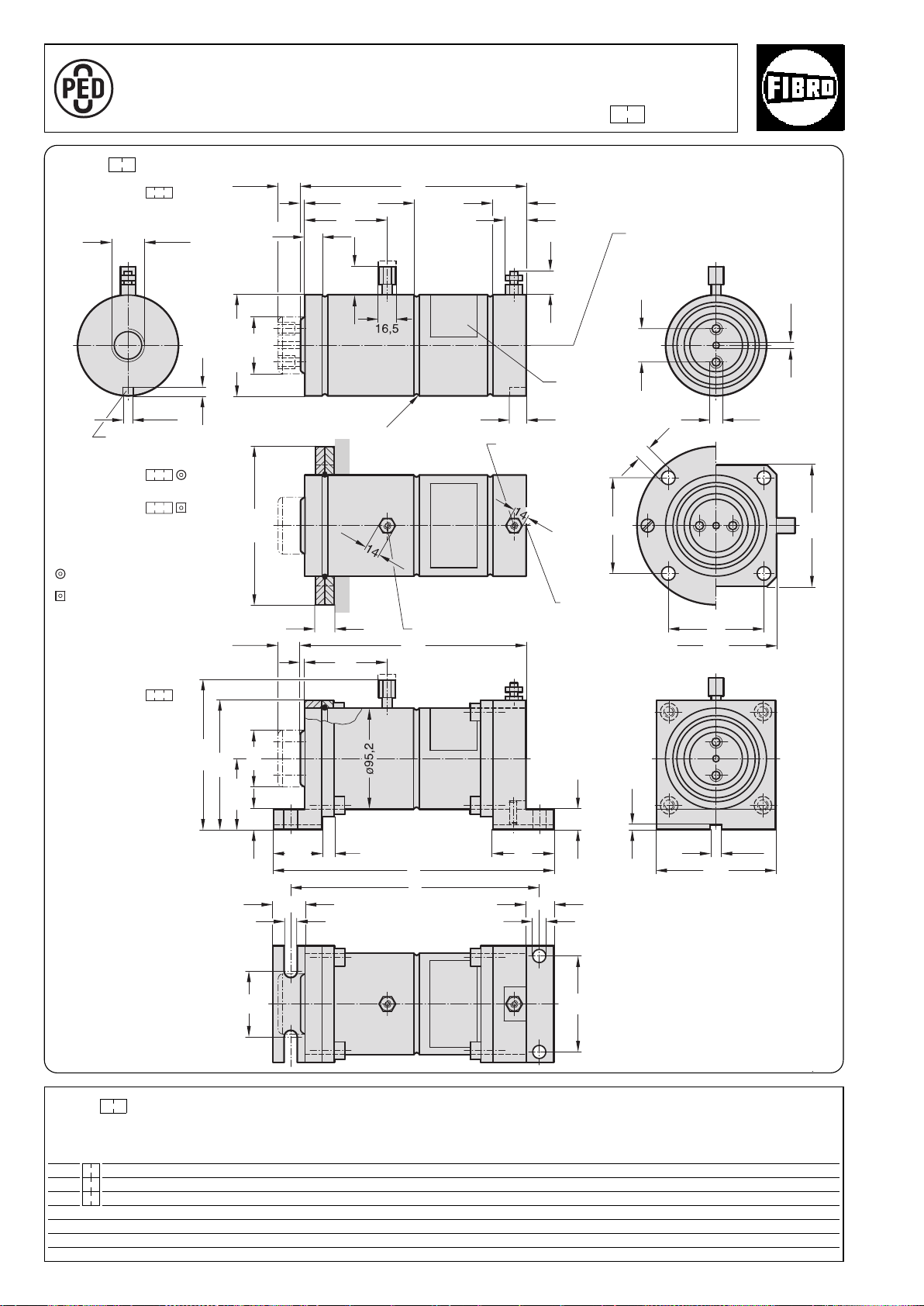
Force Cylinder 60 kN 2018. .06000.
A
P
P
R
O
V
E
D
9
7
/
2
3
/
E
C
15
+0,2
ø13
16
11
ø13
26
b
28
84
63
110
3
78
19
a
5846,5
121
66,5
19 ø50
110
92
ø150
32
78
M12
ø50
26*
8
3
/
4
G
+0,2
10
2018.30.06000.
2018.50.06000.
2018.60.06000.
2480.055.03000
2480.057.03000
2018.40.06000.
30
19
3
31
R2,5
l
min
18,5
ø95,2
±0,1
ø6
103,5
92
3)
18
110
140*
l
min
+0,1
10
4
±0,1
2018. .06000.
Spare parts
Mounting flanges
Stroke
Torsion protection groove
Stroke
Stroke
Stroke
Stroke
2)
3
Hydraulic connection G
/
4
Rating plate
Bleeder valve
Nitrogen gas
2)
connection
1)
Hydraulic
connection G
3
/
4
Stroke
Spare parts
Mounting flanges
On the piston rod
2480.045.03000
On the hydraulic
connector
2480.046.03000
* + 4,5 mm with sealing stopper
2018. .06000.
Force Cylinder (max. 40 bar)
Order no Stroke l
2018. .06000.025 25 211 262 235 6,1 12,3
min
abStroke start Stroke end
Restoring force in kN*
2018. .06000.050 50 261 312 285 6,1 12,3
2018. .06000.100 100 361 412 385 6,1 12,3
30
* isothermic
1)
Nitrogen gas connector: caution – before
removing the connector check that the
cylinder has no gas pressure.
2)
Stroke length: Important – the nominal
stroke length must be maintained from the
very start by means of an external stop.
The unused residual stroke is required as
a compression chamber for the nitrogen
gas, if the gas pressure will increase and
may cause damage.
3)
This fastening may only be subjected to
pressure (by support).
at 20 bar
subject to alterations
°
°
2·14198·2001· 2
Page 31

°
2·16287·2001· 1
subject to alterations
31
Page 32
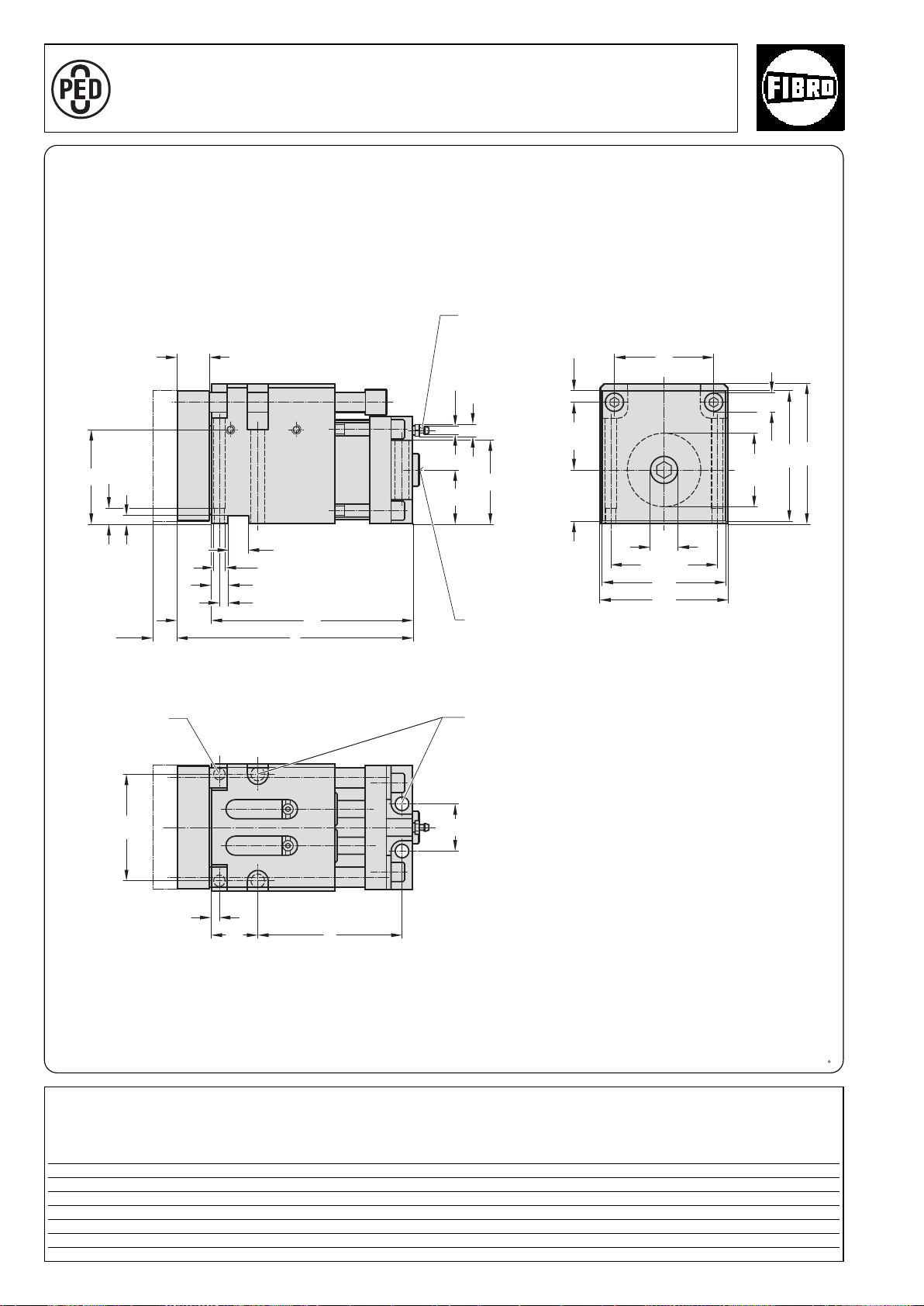
11,5
12
7
ø10
100
±0,015
ø18 (2x)
120
133
124
32
94
117
ø26
20
+0,02
-0
±0,015
(2x)
16
8
±0,015
30
51
80
ø7,5
11
e
44
8
45
100
48,5
l
1
l
90
ø70
1)
Compact Cam 60 kN 2018.11.06000.
A
P
P
R
O
V
E
D
9
7
/
2
3
/
E
C
2018.11.06000.
Venting M10x1
Max.
stroke
Locating pin
10 (2x)
Hydraulic connection
G3/4
M12 fixing screw (4x)
Note:
The punch should preferably be mounted
in the middle of the piston rod.
1)
It can also be located in the shaded area
if necessary.
A guide bolster with external guide to
absorb the lateral forces should be
provided for coping and cutting
operations.
2018.11.06000.
Compact Cam Max. at 180 bar
Order No stroke e l l1 Stroke start Stroke end
2018.11.06000.024 24 137 223 191 7 10,6
049 49 162 248 216 7 10,6
099 99 212 298 266 7 10,6
32
Restoring force in kN
°
2·14200·2001· 2
subject to alterations
Page 33
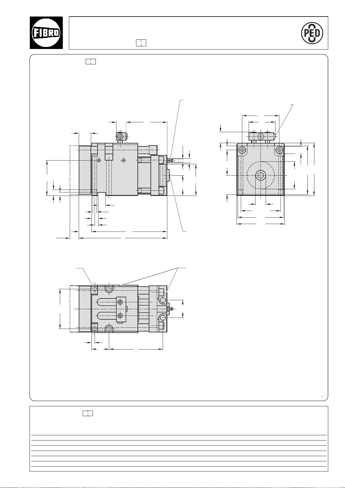
11,5
90
12
7
ø10
100
±0,015
ø18 (2x)
28
120
133
124
32
94
117
ø26
20
+0,02
-0
±0,015
(2x)
16
8
±0,015
30
51
80
ø7,5
11
e
44
8
45
100
l
1
l
l
2
25
48,5
66
ø70
1)
Compact Cam 60 kN
A
P
P
R
O
V
E
D
9
7
/
2
3
/
E
C
2018.11.06000. .1 with gas monitoring connection
2018.11.06000. .1
Install together with measuring hose and control fitting (gas spring and nitrogen connection are valveless).
Duplicate nitrogen gas ports for connecting the measuring hose.
Use only one port whilst keeping the other one closed.
Max.
stroke
Locating pin
10 (2x)
Venting M10x1
Additional nitrogen gas
port G1/8
Hydraulic connection
3
/4
G
M12 fixing screw (4x)
Note:
1)
The punch should preferably be mounted
in the middle of the piston rod.
It can also be located in the shaded area if
necessary.
A guide bolster with external guide to
absorb the lateral forces should be
provided for coping and cutting operations.
2018.11.06000. .1
Restoring force in kN
33
Compact Cam max. at 180 bar
Order No stroke e l l1 l2 Stroke start Stroke end
2018.11.06000.024.1 24 137 223 191 103 7 10,6
2018.11.06000.049.1 49 162 248 216 153 7 10,6
2018.11.06000.099.1 99 212 298 266 228 7 10,6
°
2·14199·2001· 2
subject to alterations
Page 34
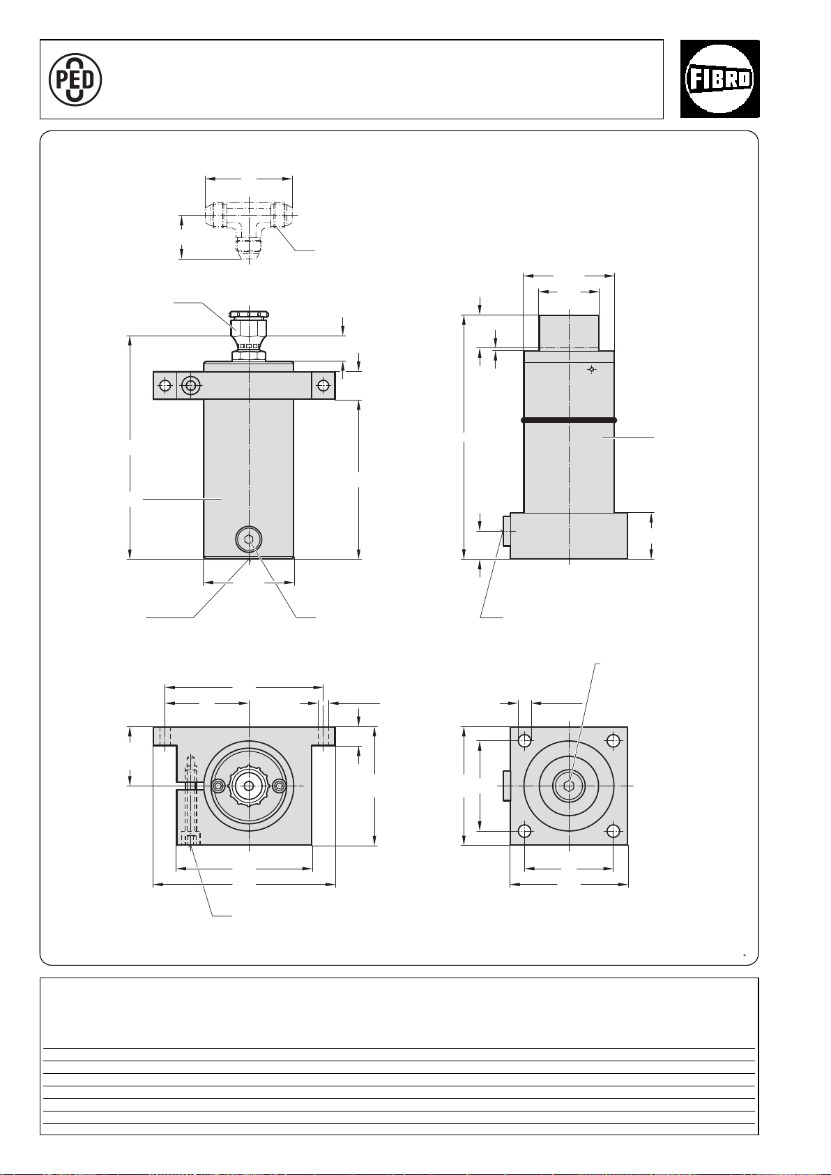
Power Unit 60 kN
46
92
27
30
2
l
1
l
ø95,1
50
30
l
ø65
ø95,1
3
62,5
20
125
145
195
ø13 (x2)
90
170
ø13 (x4)
95
125
125
95
A
P
P
R
O
V
E
D
9
7
/
2
3
/
E
C
with separate Accumulator 2018.25.06000.
2018.25.06000.
Hydraulic connection
1,5
/16"-12
JIC
Nominal hose size G1
1)
Stroke
Accumulator
Rupture protection
device
Nitrogen gas
connection G
Power Cylinder
1
/8
Hydraulic connection G3/4
1
/4
Hydraulic filling opening G
* Tighten M8 fixing screw to 25 Nm
Fixing screw*
1)
The overtravel compensation is the nominal stroke + 10 mm additional stroke.
2018.25.06000.
Power Unit
Order No stroke+10
1)
ll1l
2018.25.06000.035 35 258 235 168
2018.20.06000.060 60 308 285 218
2018.20.06000.110 110 408 385 318
2018.20.06000.160 160 508 485 418
34
2
°
2·16292· 2001·1
subject to alterations
Page 35
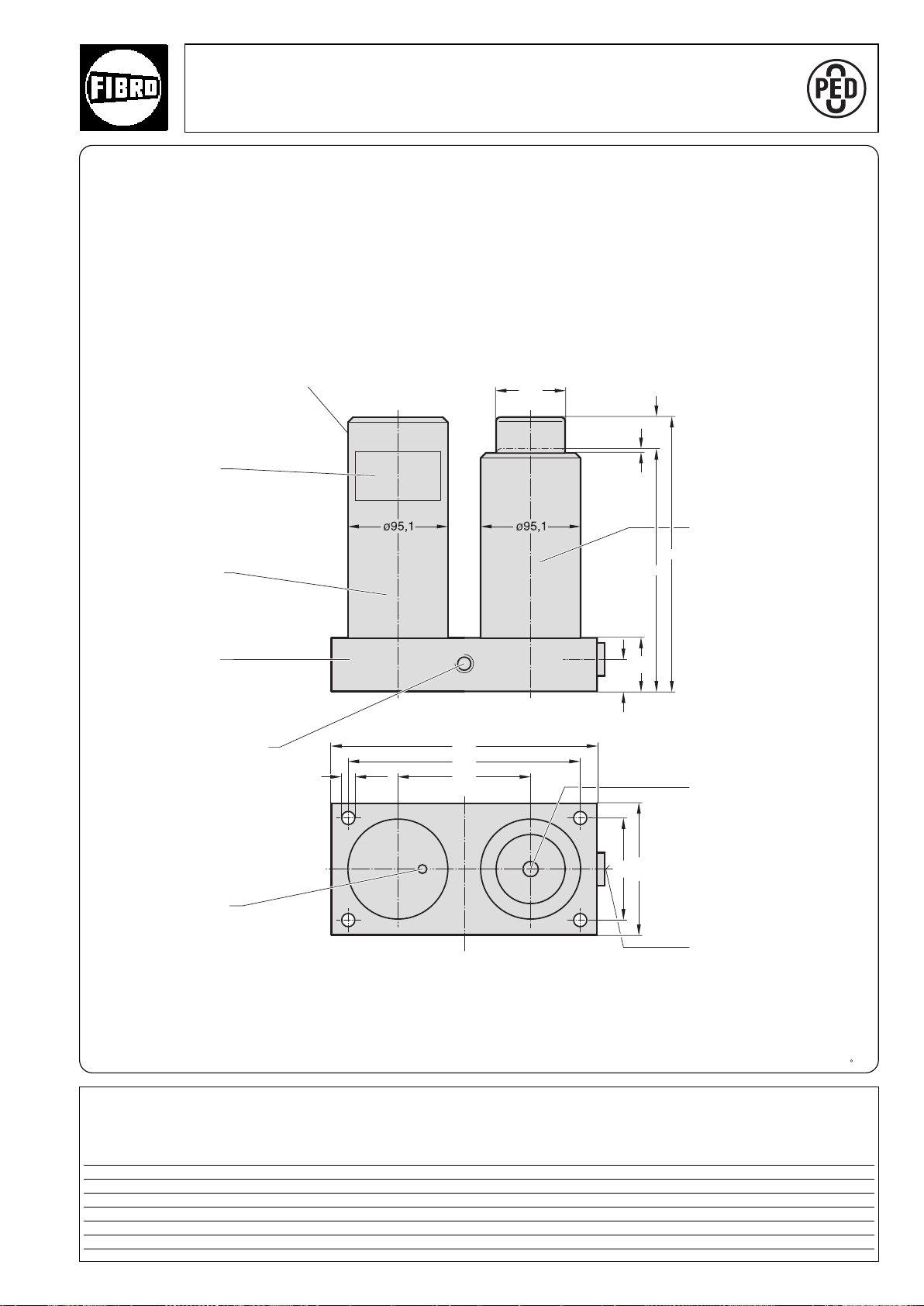
2018.20.06000. Power Unit 60 kN
A
P
P
R
O
V
E
D
9
7
/
2
3
/
E
C
ø13
30
220
250
125
ø65
125
95
50
3
l
c
2018.20.06000.
Nitrogen gas connection
Rating plate
Accumulator
Adapter plate
M12 for lifter stud
(2x)
G1/8
1)
Stroke
Power Cylinder
Hydraulic filling opening
G1/4
Rupture protection device
Hydraulic connection G
3
/4
1)
The overtravel compensation is the nominal stroke + 10 mm additional stroke.
2018.20.06000.
Power Unit Stroke
Order No. c l +10
1)
2018.20.06000.035 223 258 35
2018.20.06000.060 248 308 60
2018.20.06000.110 298 408 110
°
2018.20.06000.160 348 508 160
2·14201·2001· 2
subject to alterations
35
Page 36
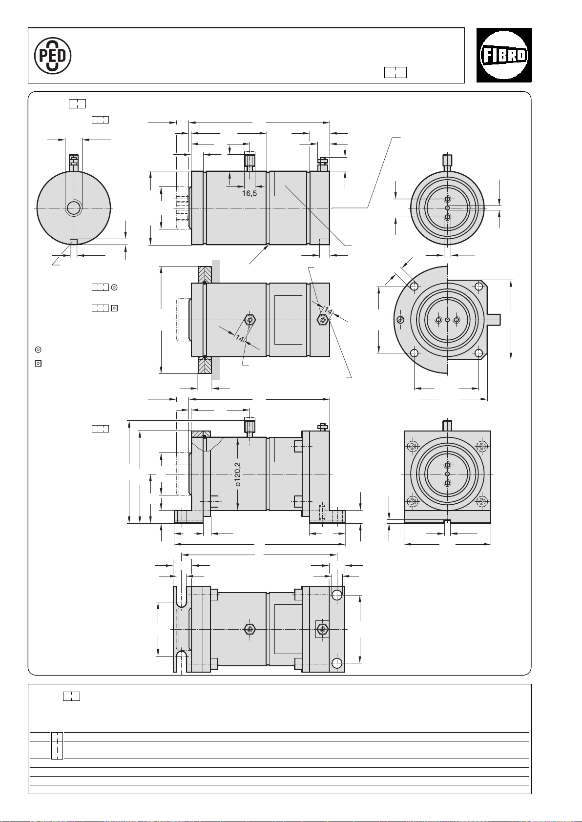
ø13
18
16
b
26
116
88
140
l
min
95
58
48
165*
149
19
79
ø65
130
130
109,5
109,5
3)
21
ø175
30
31
l
min
32
19
123
3
20
26*
ø65
ø120,2
±0,1
M12
8
3
/
4
G
+0,2
10
2018.30.09000.
2018.50.09000.
2018.60.09000.
2480.055.05000
2480.057.05000
+0,2
ø6
R2,5
95
11,5
a
3
19
2018.40.09000.
+0,1
10
4
±0,1
ø17
28
Force Cylinder 90 kN 2018. .09000.
A
P
P
R
O
V
E
D
9
7
/
2
3
/
E
C
2018. .09000.
Torsion protection groove
Spare parts
Mounting flanges
Spare parts
Mounting flanges
On the piston rod
2480.045.05000
On the hydraulic
connector
2480.046.05000
Stroke
Stroke
2)
3
Hydraulic connection G
/4
Rating plate
Bleeder valve
1)
Stroke
Stroke
Nitrogen gas connection
Hydraulic connection G3/4
Stroke
Stroke
2)
* +4,5 mm with sealing stopper
2018. .09000.
Force Cylinder (max. 40 bar)
1)
2)
3)
Restoring force in kN*
at 20 bar
Order no Stroke l min abStroke start Stroke end
2018. .09000.025 25 229 280 254 9,1 18,1
2018. .09000.050 50 279 330 304 9,1 18,1
2018. .09000.100 100 379 430 404 9,1 18,1
36
* isothermic
Nitrogen gas connector: caution – before
removing the connector check that the
cylinder has no gas pressure.
Stroke length: Important – the nominal
stroke length must be maintained from the
very start by means of an external stop.
The unused residual stroke is required as a
compression chamber for the nitrogen gas,
if the gas pressure will increase and may
cause damage.
This fastening may only be subjected to
pressure (by support).
subject to alterations
°
°
2·14202·2001· 2
Page 37

°
2·14203·2001· 2
subject to alterations
37
Page 38
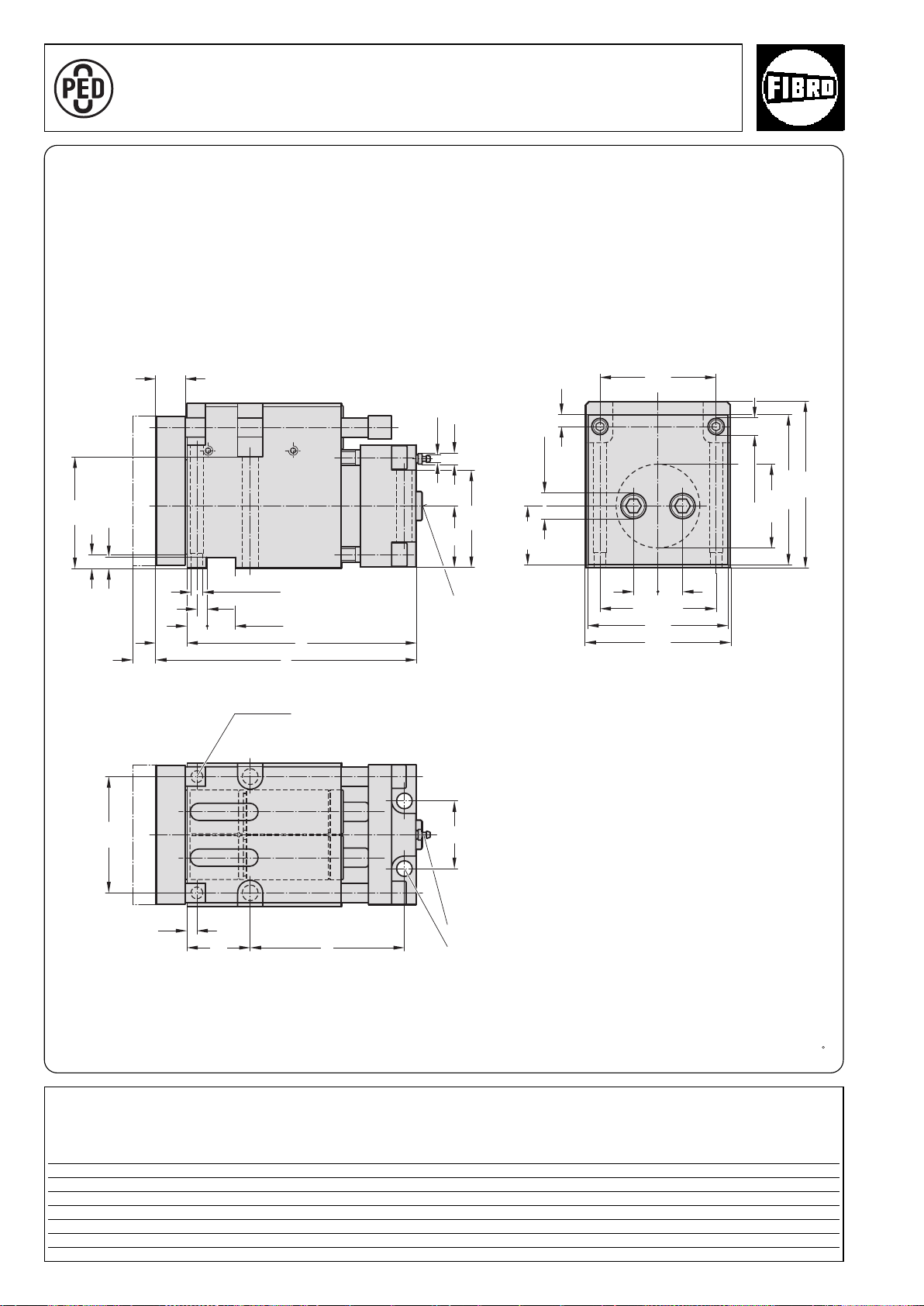
Compact Cam 90 kN 2018.11.09000.
A
P
P
R
O
V
E
D
9
7
/
2
3
/
E
C
ø90
1)
12
±0,015
120
ø17,5(2x)
+0,02
(2x)ø12
115
11
15
30
10
±0,015
+0,02
30
20
32
l
1
l
100
63
10
e
65
70
120
25 25
144
148
154,5
170
120
ø26(2x)
60,5
11
ø7,5
2018.11.09000.
stroke
Max.
Locating pin 12 (2x)
Hydraulic connection
3
/4
G
Venting
M16 fixing screw (4x)
Note:
The punch should preferably be mounted
1)
in the middle of the piston rod.
It can also be located in the shaded area
if necessary.
A guide bolster with external guide to
absorb the lateral forces should be
provided for coping and cutting
operations.
2018.11.09000.
Compact Cam Max. at 180 bar
Order No stroke e l l1 Stroke start Stroke end
2018.11.09000.024 24 159 268 236 10 14,6
049 49 184 293 261 10 14,4
099 99 234 343 311 10 14,2
38
Restoring force in kN
°
2·14204·2001· 2
subject to alterations
Page 39
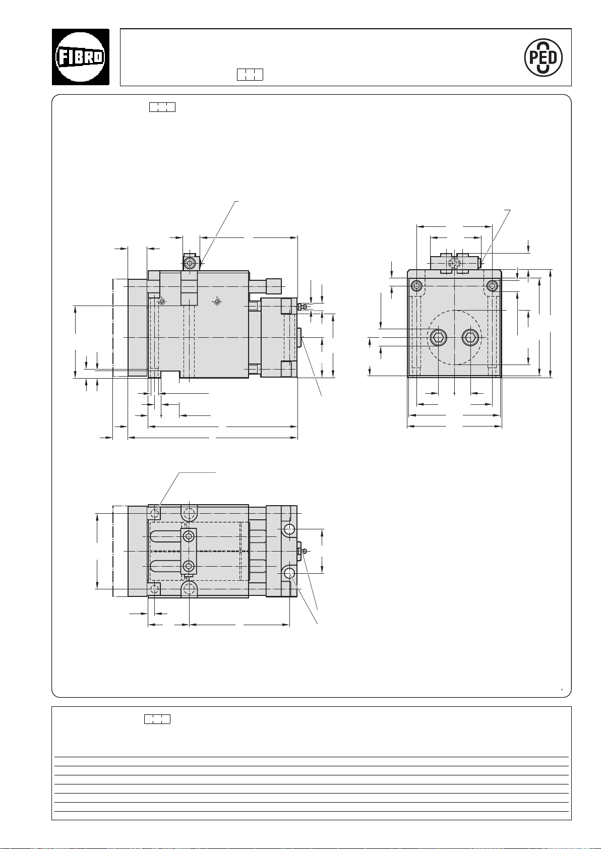
100
12
25,5
76,5
l
2
25
115
11
15
63
11
ø7,5
+0,02
(2x)ø12
10
±0,015
+0,02
30
20
32
l
1
l
30
10
e
65
120
70
±0,015
120
25 25
144
148
ø17,5(2x)
154,5
170
ø26(2x)
60,5
120
ø90
1)
Compact Cam 90 kN
A
P
P
R
O
V
E
D
9
7
/
2
3
/
E
C
2018.11.09000. .1 with gas monitoring connection
2018.11.09000. .1
Install together with measuring hose and control fitting (gas spring and nitrogen connection are valveless).
Duplicate nitrogen gas ports for connecting the measuring hose.
Use only one port whilst keeping the other one closed.
Max.
stroke
Nitrogen gas connection
G1/8
Additional nitrogen gas
port G1/8
Locating pin 12 (2x)
Hydraulic connection
3
/4
G
Venting M10x1
M16 fixing screw (4x)
Note:
The punch should preferably be mounted
in the middle of the piston rod.
1)
It can also be located in the shaded area
if necessary.
A guide bolster with external guide to
absorb the lateral forces should be
provided for coping and cutting
operations.
2018.11.09000. .1
Compact Cam max. at 150 bar
Order No stroke e l l1 l2 Stroke start Stroke end
2018.11.09000.024.1. 24 159 268 236 158 10 14,6
2018.11.09000.049.1. 49 184 293 261 208 10 14,4
2018.11.09000.099.1. 99 234 343 311 283 10 14,2
°
2·16297·2001· 1
subject to alterations
Restoring force in kN
39
Page 40
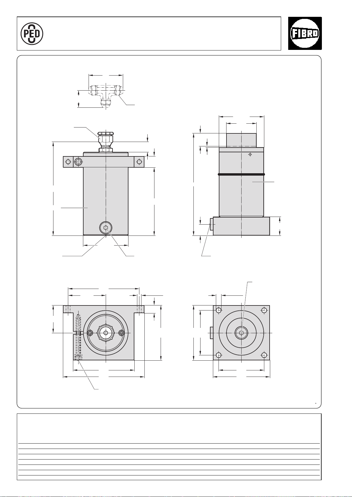
Power Unit 90 kN
46
92
27
1
l
30
2
l
ø120,1
l
ø80
3
ø120,1
30
50
74
20
148
ø13 (x2)
102,5
195
165
220
ø13 (x4)
120
150
150
120
A
P
P
R
O
V
E
D
9
7
/
2
3
/
E
C
with separate Accumulator 2018.25.09000
2018.25.09000.
Hydraulic connection
1,5
JIC
/16"-12
Nominal hose size G1
1)
Stroke
Power Cylinder
Accumulator
Rupture protection
device
Nitrogen gas
connection G
1
/8
Hydraulic connection G3/4
1
/4
Hydraulic filling opening G
Fixing screw*
1)
* Tighten M8 fixing screw to 25 Nm
The overtravel compensation is the nominal stroke + 10 mm additional stroke.
2018.25.09000.
Power Unit
Order No stroke+10
1)
ll1l
2018.25.09000.035 35 276 253 186
2018.20.09000.060 60 326 303 236
2018.20.09000.110 110 426 403 336
2018.20.09000.160 160 526 503 436
40
2
°
2·16302· 2001·1
subject to alterations
Page 41
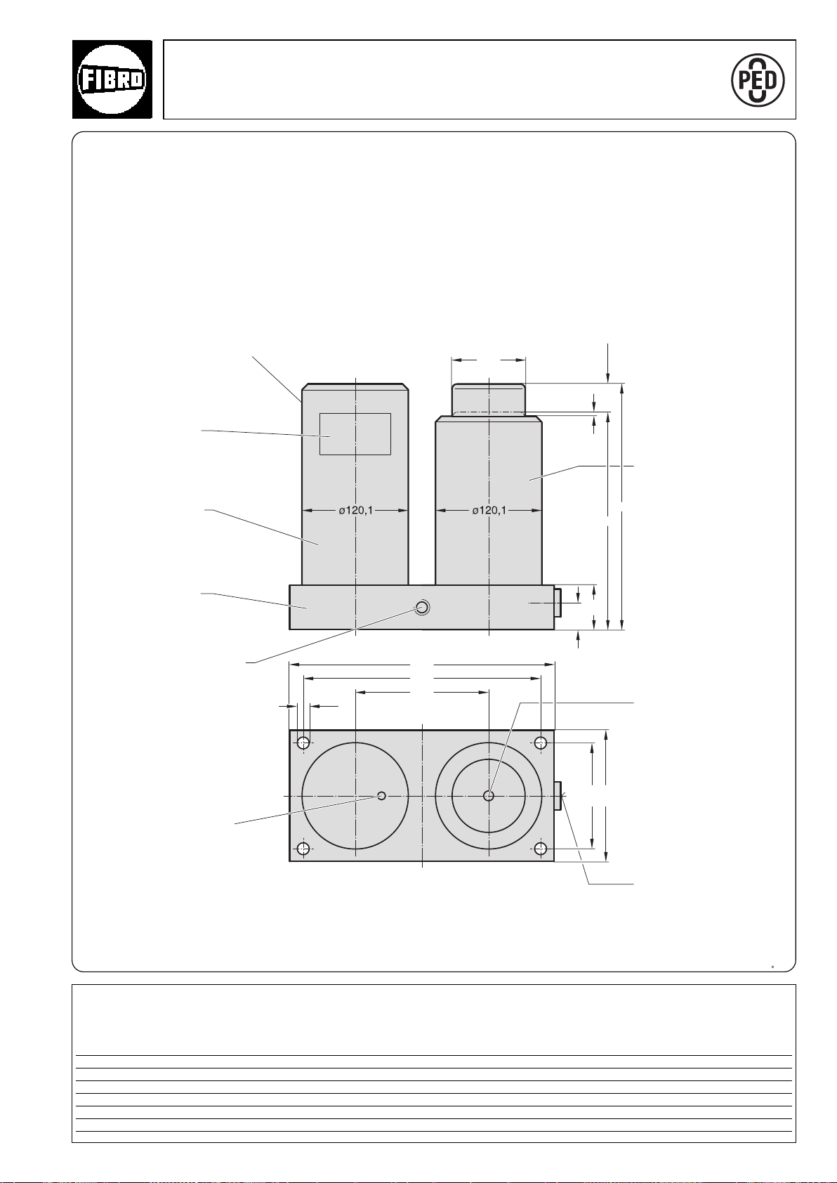
ø13
30
300
150
270
ø80
150
120
l
c
50
3
2018.20.09000. Power Unit 90 kN
A
P
P
R
O
V
E
D
9
7
/
2
3
/
E
C
2018.20.09000.
Nitrogen gas connection G
Rating plate
Accumulator
1
/8
1)
Stroke
Power Cylinder
Adapter plate
M12 for lifter stud
(2x)
Rupture protection device
1)
The overtravel compensation is the nominal stroke + 10 mm additional stroke.
1
Hydraulic filling opening G
/4
Hydraulic connection G3/4
2018.20.09000.
Power Unit Stroke
Order No. c l +10
1)
2018.20.09000.035 241 276 35
2018.20.09000.060 266 326 60
2018.20.09000.110 316 426 110
°
2018.20.09000.160 366 526 160
2·14305·2001· 2
subject to alterations
41
Page 42
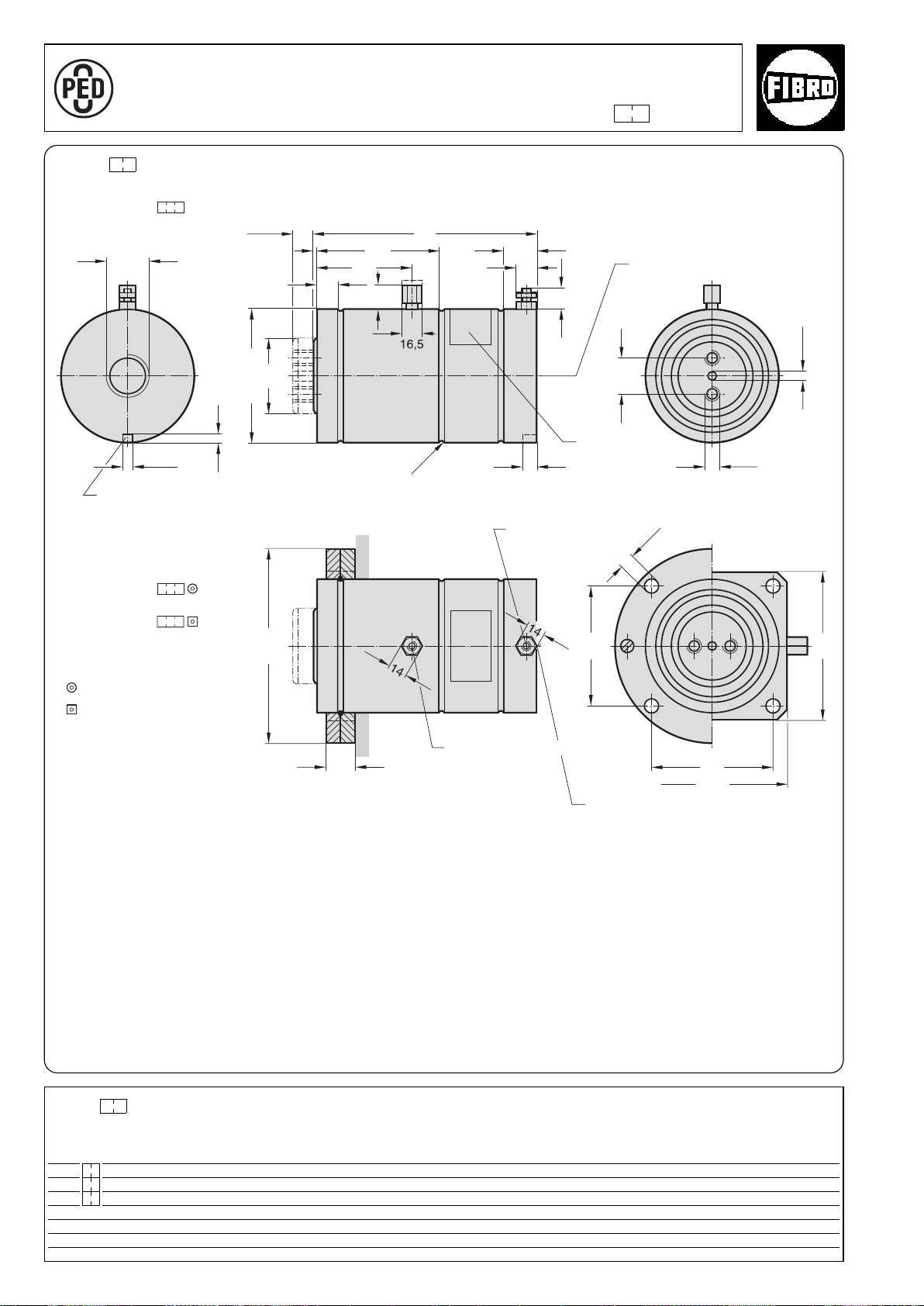
ø17,5
1
/
4
G1
16
162
138
138
3)
27
ø220
+0,2
ø10
40
37
19
31
3
136
106
22
26*
ø80
l
min
ø150,2
±0,1
M16
8
+0,2
12
2018.30.15000.
R2,5
2018.50.15000.
2018.60.15000.
2480.055.07500
2480.057.07500
162
O
R
V
P
E
D
P
A
9
C
7
/
E
/
2
3
2018. .15000.
Torsion protection groove
Spare parts
Mounting flanges
Force Cylinder 150 kN 2018. .15000.
Stroke
2)
Stroke
Hydraulic connection G1
Rating plate
Bleeder valve
Stroke
Stroke
1
/
4
Nitrogen gas connection
1)
Nitrogen gas connector: caution – before removing the connector check
that the cylinder has no gas pressure.
2)
Stroke length: Important – the nominal stroke length must be
maintained from the very start by means of an external stop.
The unused residual stroke is required as a compression chamber for
the nitrogen gas, if the gas pressure will increase and may cause
damage.
3)
This fastening may only be subjected to pressure (by support).
Restoring force in kN*
* +4,5 mm with sealing stopper
2018. .15000.
at 20 bar
Force Cylinder (max. 40 bar)
Order no Stroke l
2018. .15000.025 25 250 14,5 29,0
min
Stroke start Stroke end
2018. .15000.050 50 300 14,5 29,0
2018. .15000.100 100 400 14,5 29,0
* isothermic
1)
Hydraulic
connection G1
1
/
4
°
°
42
2·14206·2001· 2
subject to alterations
Page 43

°
2·18714·2003· 1
subject to alterations
43
Page 44
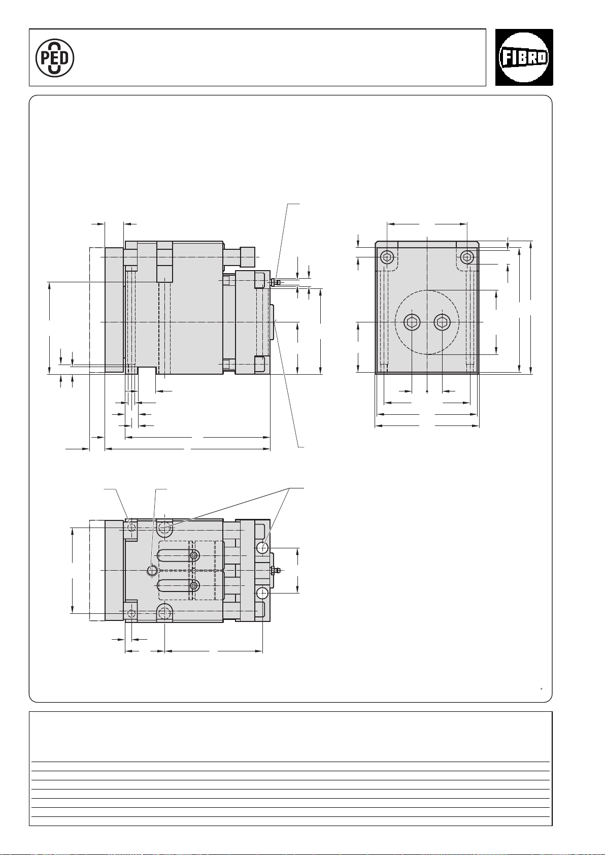
Compact Cam 150 kN 2018.11.15000.
A
P
P
R
O
V
E
D
9
7
/
2
3
/
E
C
15
20
ø20 (2x)
134
±0,015
156
2525
160
205
193
80
ø7,5
11
132
ø12
32
30
+0,02
-0
±0,015
(2x)
10
±0,015
11
15
142
30
134
70
e
65
10
124
l
1
l
78
ø100
1)
2018.11.15000.
Venting M10x1
Max.
stroke
Locating pin
12 (2x)
Lifting thread M16
Hydraulic connection
1
/4
G1
M16 fixing screw (4x)
Note:
1)
The punch should preferably be mounted
in the middle of the piston rod.
It can also be located in the shaded area
if necessary.
A guide bolster with external guide to
absorb the lateral forces should be
provided for coping and cutting
operations.
2018.11.15000.
Restoring force in kN
Compact Cam Max. at 180 bar
Order No stroke e l l1 Stroke start Stroke end
2018.11.15000.024 24 159 268 236 15 24
049 49 184 293 261 15 24
099 99 234 343 311 15 24
43/1
°
2·14200·2001· 2
subject to alterations
Page 45
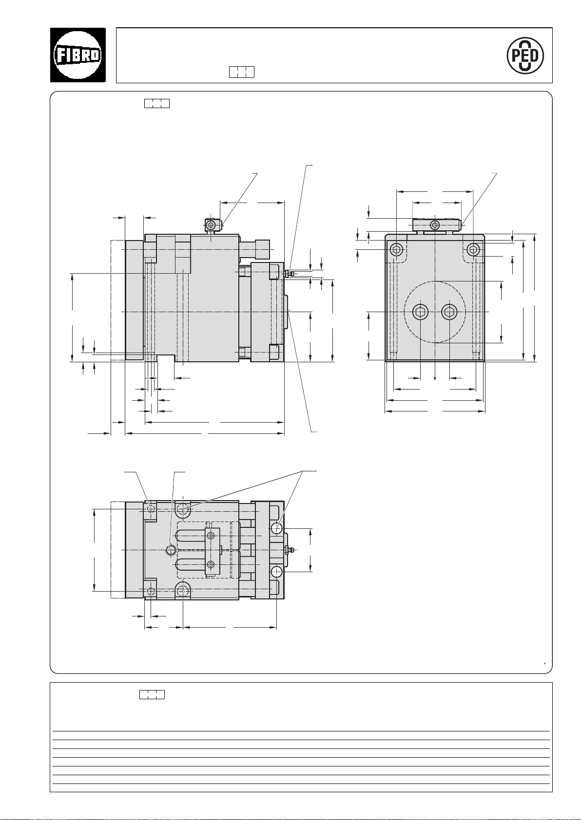
20
ø20 (2x)
134
±0,015
156
2525
160
205
193
ø100
27
80
ø7,5
11
132
ø12
32
30
+0,02
-0
±0,015
(2x)
10
±0,015
11
15
142
30
134
70
e
65
10
124
78
l
1
l
l
2
78
15
1)
Compact Cam 150 kN
A
P
P
R
O
V
E
D
9
7
/
2
3
/
E
C
2018.11.15000. .1 with gas monitoring connection
2018.11.15000. .1
Install together with measuring hose and control fitting (gas spring and nitrogen connection are valveless).
Duplicate nitrogen gas ports for connecting the measuring hose.
Use only one port whilst keeping the other one closed.
Max.
stroke
Locating pin
12 (2x)
Nitrogen gas
connection G1/8
Venting M10x1
Hydraulic connection
1
/4
G1
M16 fixing screw (4x)Lifting thread M16
Additional nitrogen gas
port G1/8
Note:
1)
The punch should preferably be mounted
in the middle of the piston rod.
It can also be located in the shaded area
if necessary.
A guide bolster with external guide to
absorb the lateral forces should be
provided for coping and cutting
operations.
2018.11.15000. .1
Restoring force in kN
Compact Cam max. at 150 bar
Order No stroke e l l1 l2 Stroke start Stroke end
2018.11.15000.024.1. 24 159 268 236 109 15 24
2018.11.15000.049.1. 49 184 293 261 159 15 24
2018.11.15000.099.1. 99 234 343 311 234 15 24
°
2·14207·2001· 2
subject to alterations
43/2
Page 46
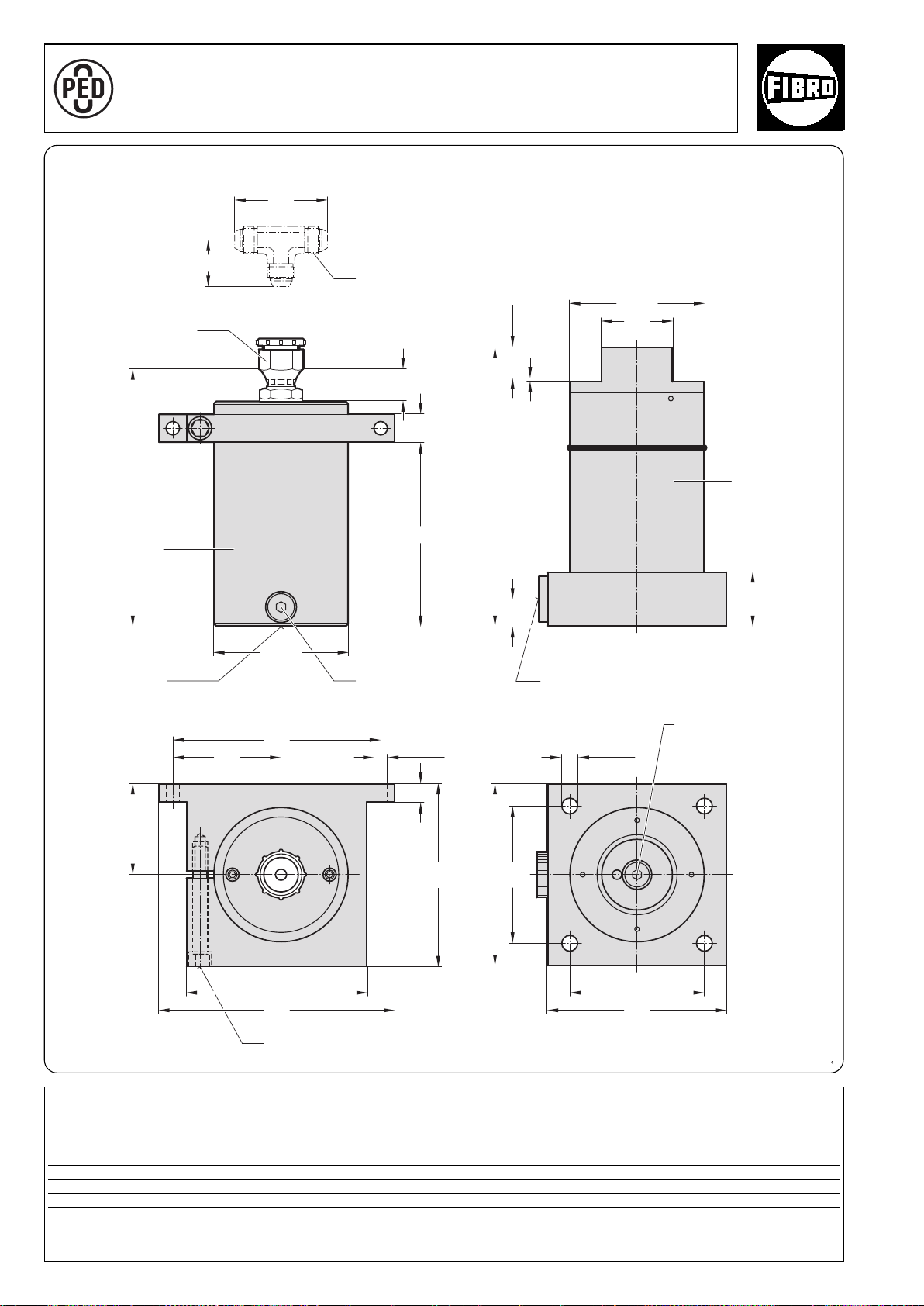
Power Unit 150 kN
33
30
2
l
1
l
100
20
200
52
60
30
l
ø80
ø150,1
ø17 (x4)
150
200
200
260
ø13 (x2)
120
230
ø150,1
104
3
200
150
A
P
P
R
O
V
E
D
9
7
/
2
3
/
E
C
with separate Accumulator 2018.25.15000
2018.25.15000.
Hydraulic connection
1,5
/16"-12
JIC
Nominal hose size G1
1
/4
1)
Stroke
Power Cylinder
Accumulator
Rupture protection
device
Nitrogen gas
connection G
1
/8
Hydraulic connection G11/4
Hydraulic filling opening G1/4
* Tighten M8 fixing screw
to 25 Nm
Fixing screw*
1)
The overtravel compensation is the nominal stroke + 10 mm additional stroke.
2018.25.15000.
Power Unit
Order No stroke+10
1)
ll1l
2018.25.15000.035 35 307 280 207
2018.20.15000.060 60 357 330 257
2018.20.15000.110 110 457 430 357
44
2
°
2·16307· 2001·1
subject to alterations
Page 47
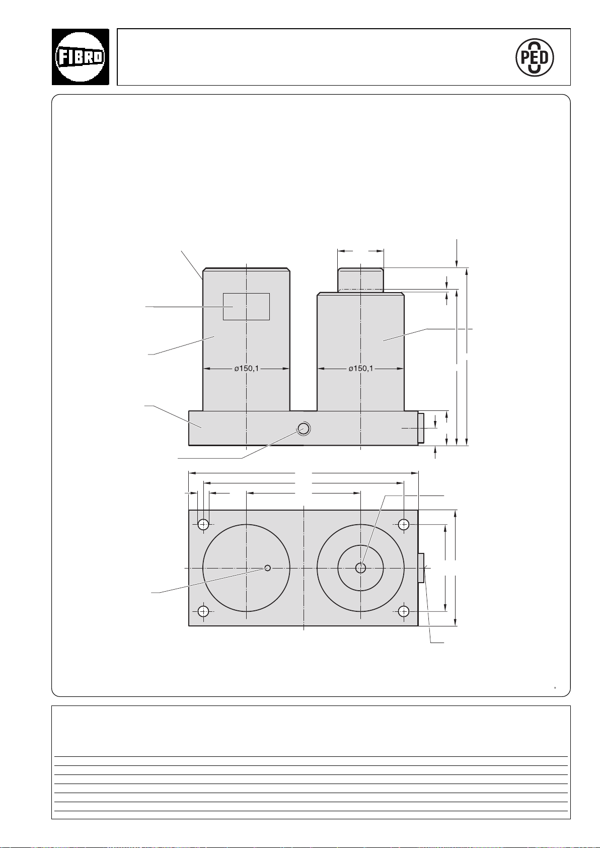
ø17
30
200
400
350
ø80
200
150
l
c
60
3
O
R
V
P
E
D
P
A
2018.20.15000. Power Unit 150 kN
2018.20.15000.
Nitrogen gas connection G
Rating plate
Accumulator
9
C
7
/
E
/
2
3
1
/8
1)
Stroke
Power Cylinder
Adapter plate
M12 for lifter stud
(2x)
Rupture protection device
1)
The overtravel compensation is the nominal stroke + 10 mm additional stroke.
1
Hydraulic filling opening G
/4
Hydraulic connection G11/4
2018.20.15000.
Power Unit Stroke
Order No. c l +10
2018.20.15000.035 272 307 35
2018.20.15000.060 297 357 60
2018.20.15000.110 347 457 110
°
2·14209·2001· 2
subject to alterations
1)
45
Page 48
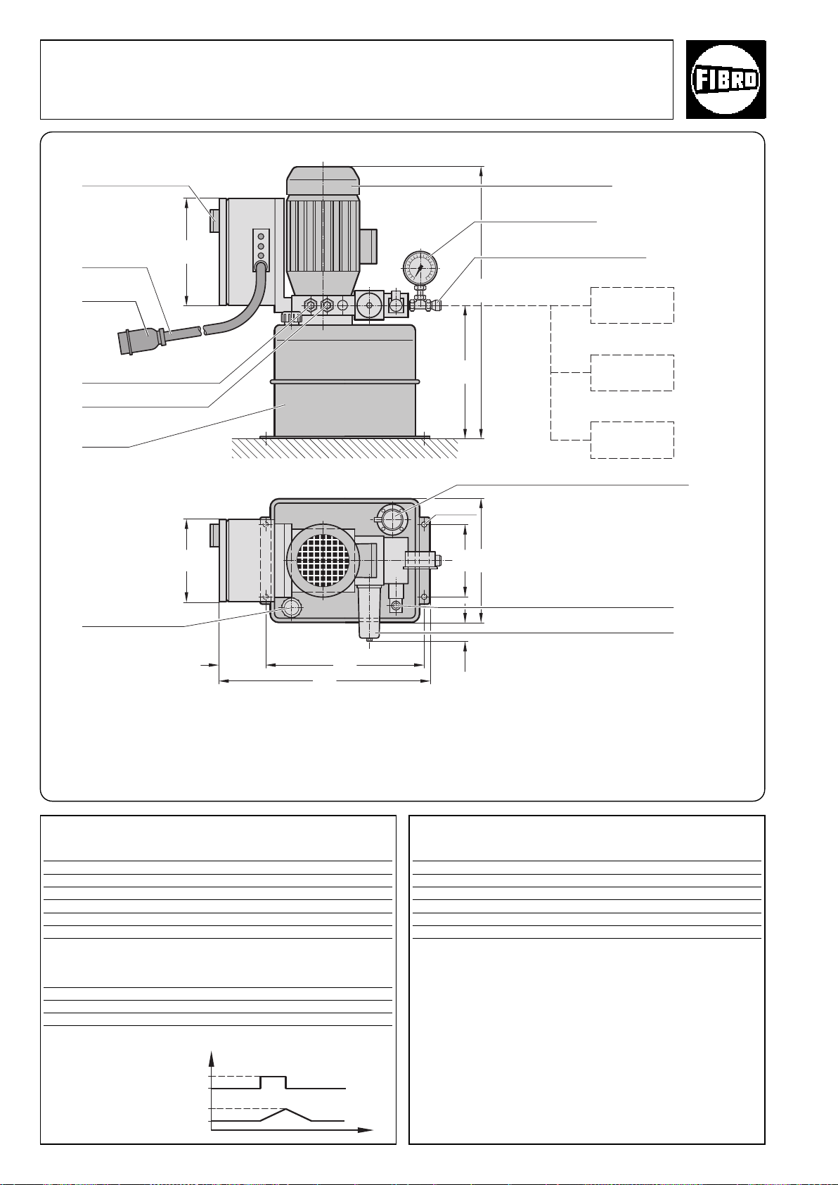
Electric hydraulic pump 2018.80.15000
37,5
275
435
32597,5
170
255
150
230
580
ø11 (4x)
2018.80.15000
Start / Stop
(Switch off
when not in
use)
cable 10 m
CEE 16 A
connector
low pressure valve
high pressure valve
(see note)
oil tank
electric motor, 0,75 kW
manometer display
1
/2″ oil connection for cam
(working unit)
Cam unit
(working unit)
oil level indicator / temperature sensor
oil capacity
(Min. 10 litres)
Note!
The pressure can be set at both valves.
We recommend setting the low pressure valve to 25 bar.
The high pressure valve can be set to a maximum of 180 bar.
The value to be set depends on the operational requirements.
Technical specifications – hydraulic system
Oil tank volume 15 l
Hydraulic oil ISO VG 32 DIN 51524 HVLP (or similar)
Min. flow at 120 bar 1,6 l/min.
Max. flow at 25 bar 8,7 l/min.
Oil pressure when extending and retracting 10-20 bar
Oil pressure during operation max. 180 bar
Low and high pressure valves (see note)
Technical specifications – electrical system
Power supply electrical pump 3x220-440 V-AC 50-60 Hz
Control voltage & control valve 24 V-DC
max. oil temperature 70+/–5° C
Reset switch-on temperature after overheating 50°C
valve control voltage 24 V - DC
Oil filter
For continuous use we recommend
replacing the oil filter cartridge
(Order no. 2018.80.15000.002.1)
every 6 months
Cam speeds*
Size of cam (Low pressure phase) (high pressure phase)
2018.11.01500. 115 mm/s 21 mm/s
2018.11.04000. 47 mm/s 9 mm/s
2018.11.06000. 29 mm/s 5 mm/s
2018.11.09000. 18 mm/s 3 mm/s
2018.11.15000. 12 mm/s 2 mm/s
* The table shows the approximate speeds of one cam unit
connected to an electric hydraulic pump. If several cam units are
connected to an electric hydraulic pump to obtain the speed of
each, divide by the numer of cam units.
Example: 3 x 2018.11.01500.024 : 115 mm/s = 38 mm/s
When extending and retracting during operation
°
Contol signal 24 V – DC
Cam unit
(working unit)**
46
24
Max.travel
Travel 0
0
°
** The control signal (24 V DC) triggers extension of the piston
rodand the gas overpressure in the cam unit causes retraction.
2·14210·2001· 2
subject to alterations
Page 49

Flex Cam
Accessories
°
2·14275·2001· 2
subject to alterations
47
Page 50
m
d
1
m
e e
l
1
*
d
2
DN
2·14213· 2001·2
°
subject to alterations
48
Flex Cam
Accessories
Connecting hoses and connectors 2018.00.
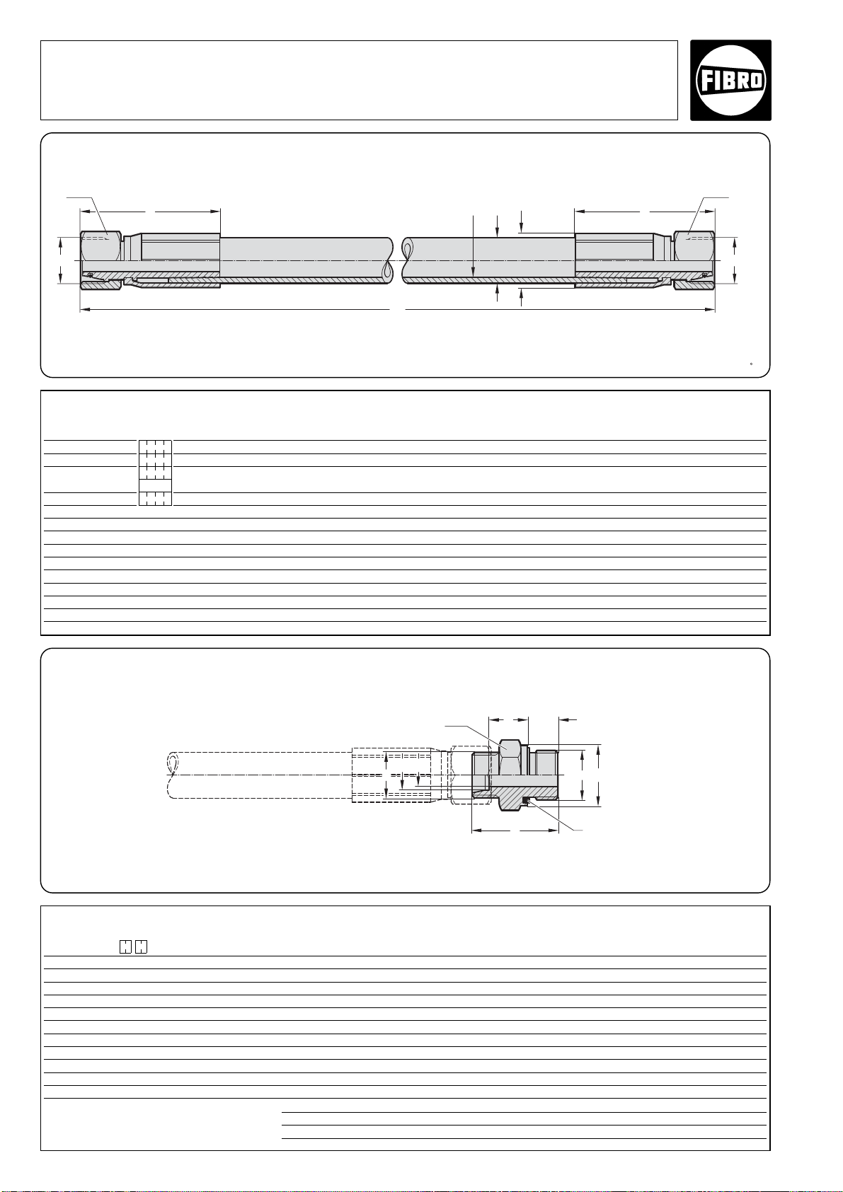
2018.00.25.01. Hose with conical seals, union nut and O ring (straight/straight)
Dimension l1specified in the order, e. g. 765 mm, gives order no. 2018.00.25.01.XX.0765
Note: 45° and 90° elbow hoses are not available.
Instead use 2018.00.26.21./22. adapters.
A/F
A/F
m
d
2
d
1
l
2
1
l
3
l
d
3
g
)
1
2018.00.26.03. Threaded connector, straight – G
1) Eolastic seal ED
A/F
2018.00.25.01.
2018.00.25.01.01. 12 01500. M24x1,5 24 28,5 63 30 90 150
2018.00.01.01.02. 20 04000. M30x2 31 35 72 36 120 165
2018.00.01.01.03. 25 06000. M36x2 38 44 88 46 150 200
09000.
2018.00.01.01.04. 32 15000. M42x2 50 55 114 50 250 250
Recommended for Hose connector thread M Minimum Shortest
Order no l
1
DN
Power Unit size
2018.20.
with (24° cone) d
1
d
2
e A/F
bend radius factory length
2018.00.26.03.
2018.00.26.03. .
2018.00.26.03.01.01 DN 12 M24x1,5 G1/
2
16 12 27 41 18,5 14 27
2018.00.26.03.01.02 G3/
4
32 45 20,5 16 32
2018.00.26.03.02.01 DN 20 M30x2 G1/
2
20 27 14
2018.00.26.03.01.02 G3/
4
16 32 47 16
2018.00.26.03.01.04 G 11/
4
50 53 22,5 20 50
2018.00.26.03.03.01 DN 25 M36x2 G1/
2
25 12 27 49 23 14 41
2018.00.26.03.01.02 G3/
4
16 32 51 16
2018.00.26.03.01.03 G 1 20 40 53 18
2018.00.26.03.01.04 G 11/
4
50 55 20 50
2018.00.26.03.04.03 DN 32 M42x2 G 1 30 40 23,5 18 46
2018.00.26.03.01.04 G 11/
4
25 50 57 20 50
Order no Nominal Hose connector Standard unit
hose size thread m thread g d
1
d
2
d
3
l
1
l
2
l
3
A/F
Ordering Code (example):
Threaded
connector, straight = 2018.00.26.03.
Nominal size DN 25 = 2018.00.26.03.03.
Male thread G 1/
2
= 2018.00.26.03.03.01
Order no = 2018.00.26.03.03.01
°
Page 51
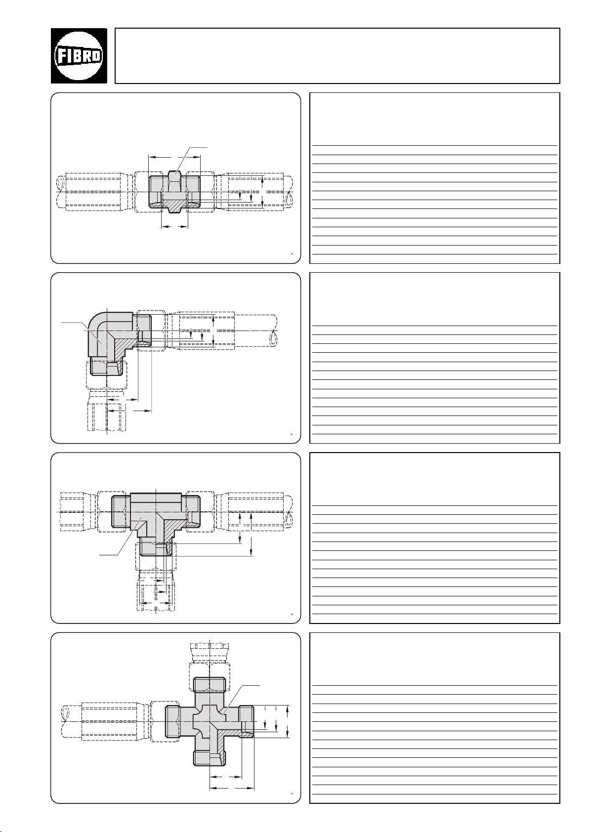
m
d
2
d
1
l
2
1
l
m
d
2d1
l
2
1
l
2
m
d2d
1
l
1
l
2
m
d
2
d
1
l
1
l
Flex Cam
Accessories
2018.00. Threaded couplings
2018.00.26.25. Adapter straight, hose–hose
A/F
2018.00.26.26. 90° adapter, hose–hose
A/F
2018.00.26.25.
Hose connector
Order no DN* m d1d2l1l2A/F
2018.00.26.25.01 12 M24x1,5 16 12 38 21 27
2018.00.26.25.02 20 M30x2 20 16 44 23 32
2018.00.26.25.03 25 M36x2 25 20 50 26 41
2018.00.26.25.04 32 M42x2 30 25 54 27 46
* DN = clear width of hose
thread M
2018.00.26.26.
Hose connector
Order no DN* m d1d2l1l
2018.00.26.26.01 12 M24x1,5 16 12 33 24,5 24
2018.00.26.26.02 20 M30x2 20 16 37 26,5 27
2018.00.26.26.03 25 M36x2 25 20 42 30 36
2018.00.26.26.04 32 M42x2 30 25 49 35,5 41
thread M
A/F
2
2018.00.26.27. T-adapter, hose–hose
A/F
2018.00.26.28.
K-adapter, hose–hose
°
* DN = clear width of hose
2018.00.26.27.
Hose connector
Order no DN* m d1d2l1l
2018.00.26.27.01 12 M24x1,5 16 12 33 24,5 24
2018.00.26.27.02 20 M30x2 20 16 37 26,5 27
2018.00.26.27.03 25 M36x2 25 20 42 30 36
2018.00.26.27.04 32 M42x2 30 25 49 35,5 41
* DN = clear width of hose
thread M
A/F
2
2018.00.26.28.
Hose connector
A/F
Order no DN* m d1d2l1l
2018.00.26.28.01 12 M24x1,5 16 12 33 24,5 24
2018.00.26.28.02 20 M30x2 20 16 37 26,5 27
2018.00.26.28.03 25 M36x2 25 20 42 30 36
2018.00.26.28.04 32 M42x2 30 25 49 35,5 41
thread M
A/F
2
2·14213·2001· 2
subject to alterations
* DN = clear width of hose
49
Page 52
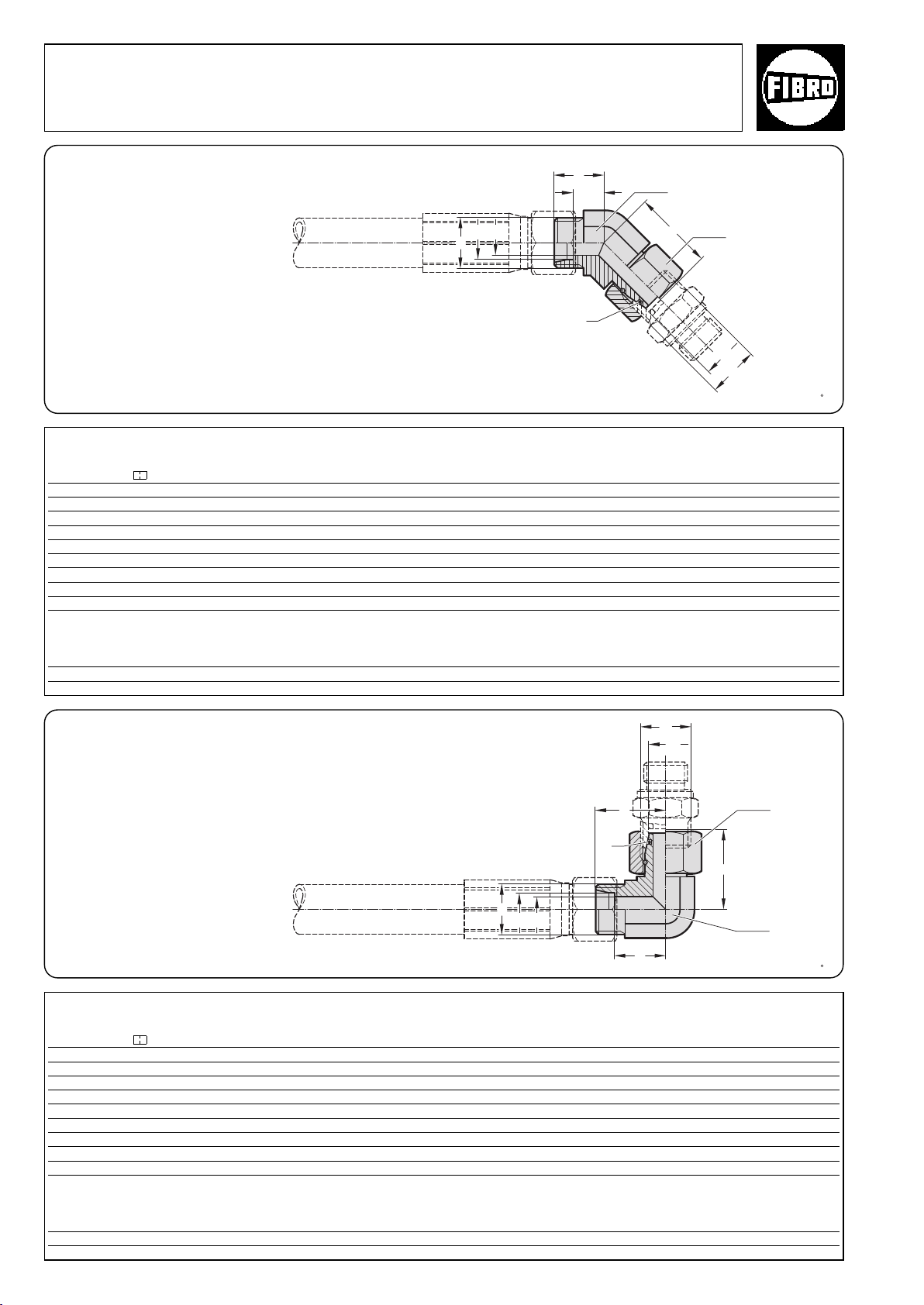
m
m
d
1
l
2
1
l
d
2
d
1
3
l
)
2
m
d
1
m
d
2
d
1
l
2
1
l
3
l
)
2
Flex Cam
Accessories
Threaded couplings 2018.00.
2018.00.26.21. 45° swivel coupling, complete
A/F
1
2018.00.26.21.
Order no. Nominal Hose coupling
2018.00.26.21. hose size thread m d
.01 DN 12 M24x1,5 16 12 24 15,5 36,5 27 30
. 02 DN 20 M30x2 20 16 26,5 16 44,5 30 36
. 03 DN 25 M36x2 25 20 30,5 18,5 50 36 46
. 04 DN 32 M42x2 30 25 37 23,5 55 50 50
d
1
l
2
1
l
2
I
3
A/F
2
A/F
2
) = O Ring
A/F
1
2
Ordering example:
45° swivel coupling = 2018.00.26.21.
Nominal size DN 25 = 2018.00.26.03.03
Order no. = 2018.00.26.21.03
2018.00.26.22. 90° swivel coupling, complete
2018.00.26.22.
Order no. Nominal Hose coupling
2018.00.26.22. hose size thread m d
.01 DN 12 M24x1,5 16 12 33 24,5 36,5 24 30
. 02 DN 20 M30x2 20 16 37 26,5 44,5 27 36
. 03 DN 25 M36x2 25 20 42 30 50 36 46
. 04 DN 32 M42x2 30 25 49 35,5 55 41 50
A/F
2
A/F
1
2
) = O Ring
d
1
l
2
1
l
2
I
3
A/F
A/F
1
2
Ordering example:
90° swivel coupling = 2018.00.26.22.
Nominal size DN 25 = 2018.00.26.03.03
Order no. = 2018.00.26.22.03
50
subject to alterations
°
2·14215·2001· 2
Page 53
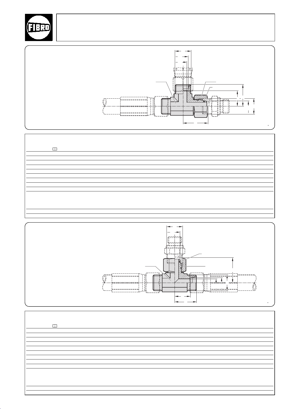
2018.00. Threaded couplings
l
2
m
d
2
d
1
l
3
1
l
m
d
1
)
2
m
d
2d1
l
2
1
l
m
d
1
l
3
)
2
2018.00.26.23. L swivel coupling, complete
Flex Cam
Accessories
2018.00.26.23.
Order no. Nominal Hose coupling
2018.00.26.23. hose size thread m d
.01 DN 12 M24x1,5 16 12 33 24,5 36,5 24 30
. 02 DN 20 M30x2 20 16 37 26,5 44,5 27 36
. 03 DN 25 M36x2 25 20 42 30 50 36 46
. 04 DN 32 M42x2 30 25 49 35,5 55 41 50
Ordering example:
L swivel coupling = 2018.00.26.23.
Nominal size DN 25 = 2018.00.26.03.03
Order no. = 2018.00.26.23.03
A/F
1
d
1
l
2
1
A/F
2
2
) = O Ring
l
2
I
3
A/F
A/F
1
2
2018.00.26.24. T swivel coupling, complete
A/F
2018.00.26.24.
Order no. Nominal Hose coupling
2018.00.26.24. hose size thread m d
Ordering example:
°
T swivel coupling = 2018.00.26.24.
Nominal size DN 25 = 2018.00.26.03.03
Order no. = 2018.00.26.24.03
2·14215·2001· 2
subject to alterations
.01 DN 12 M24x1,5 16 12 33 24,5 36,5 24 30
. 02 DN 20 M30x2 20 16 37 26,5 44,5 27 36
. 03 DN 25 M36x2 25 20 42 30 50 36 46
. 04 DN 32 M42x2 30 25 49 35,5 55 41 50
1
d
1
2
A/F
2
2
) = O Ring
l
1
l
2
I
3
A/F
A/F
1
2
51
Page 54
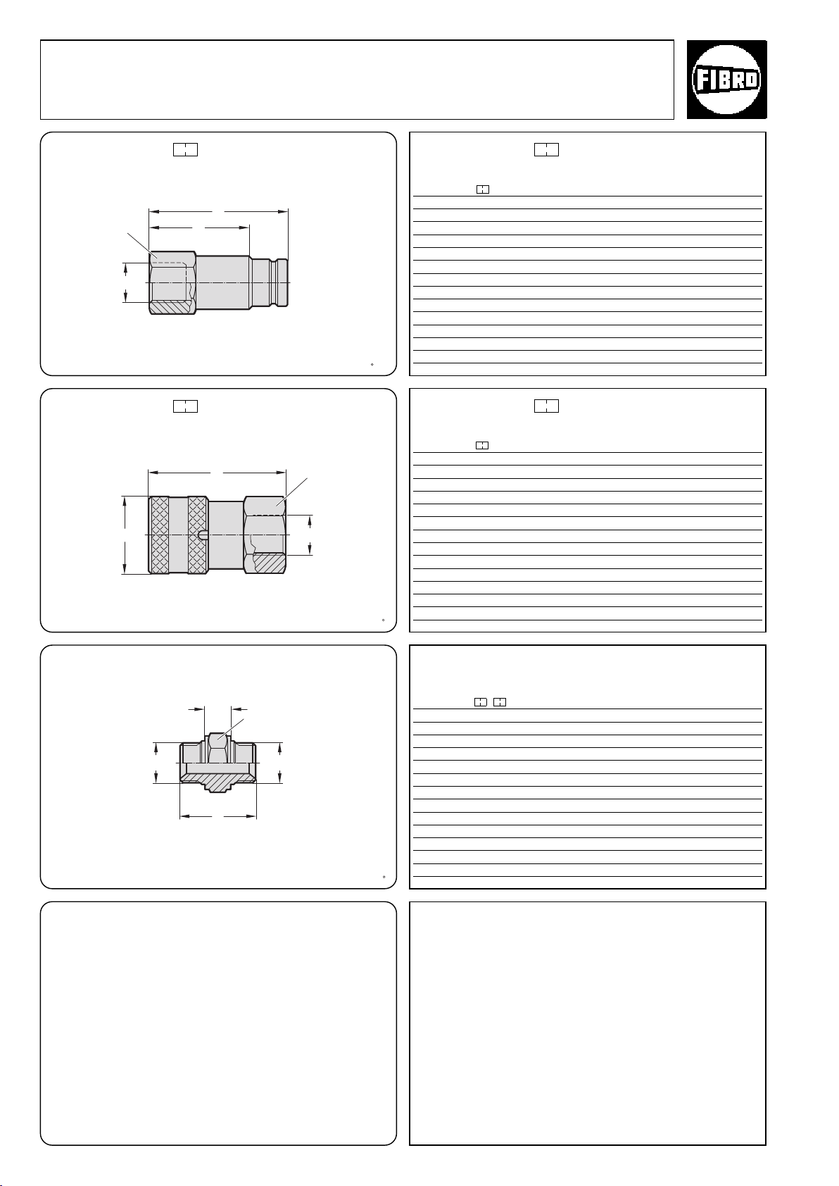
m
l
1
l
2
1
m
2
m
l
1
l
2
m
l
3
d
1
Flex Cam
Accessories
Quick-release couplings 2018.00.
2018.00.10.00. .1
A/F
2018.00.10.00. .2
Quick-release coupling,
male section
Quick-release coupling,
female section
A/F
2018.00.10.00. .1
Order number Nominal Max pressure /
2018.00.10.00. .1
hose size
01. DN12
02. DN20
m Cam Unit speed l1l2A/F *l
1
/20,8 m/s 70 54 11/8122
3
/
4
03. DN25 1 0,6 m/s 104 69 17/8174
DN32
2018.00.10.00. .2
Order number Nominal Max pressure /
2018.00.10.00. .2
hose size
01. DN12
02. DN20
m Cam Unit speed l3A/F d1*l
1
/20,8 m/s 68 13/840 122
3
/
4
03. DN25 1 0,6 m/s 105 17/857 174
DN32
86 63 11/2152
89 13/449 152
2018.00.26.
Quick-release coupling, screw-in adapter (SK)
A/F
*m
= Coupling thread for Cam Unit
1
= Coupling thread for Power Unit
**m
2
Check the press or Cam Unit speed before using the quick-release
coupling.
Turn the ring to secure the coupling.
Do not open while the oil is still warm or under pressure.
2018.00.26.
Order number Nominal
2018.00.26. . hose size m
01 . 01 DN12
01 . 02
02 . 01 DN20
02 . 02
02 . 03
03 . 02 DN25 1
03 . 03 1 1 52
04 . 03 DN32 11/41601750
m2l
1
1
1
/
/241
2
3
1
/
/444,5
2
1
3
/
/244,5
4
3
3
/
/446
4
3
/
1491532
4
3
/449
l
2
12,5
15
15
15
15
15
A/F
27
32
32
32
41
41
°
1
52
2·14216·2001· 2
subject to alterations
Page 55
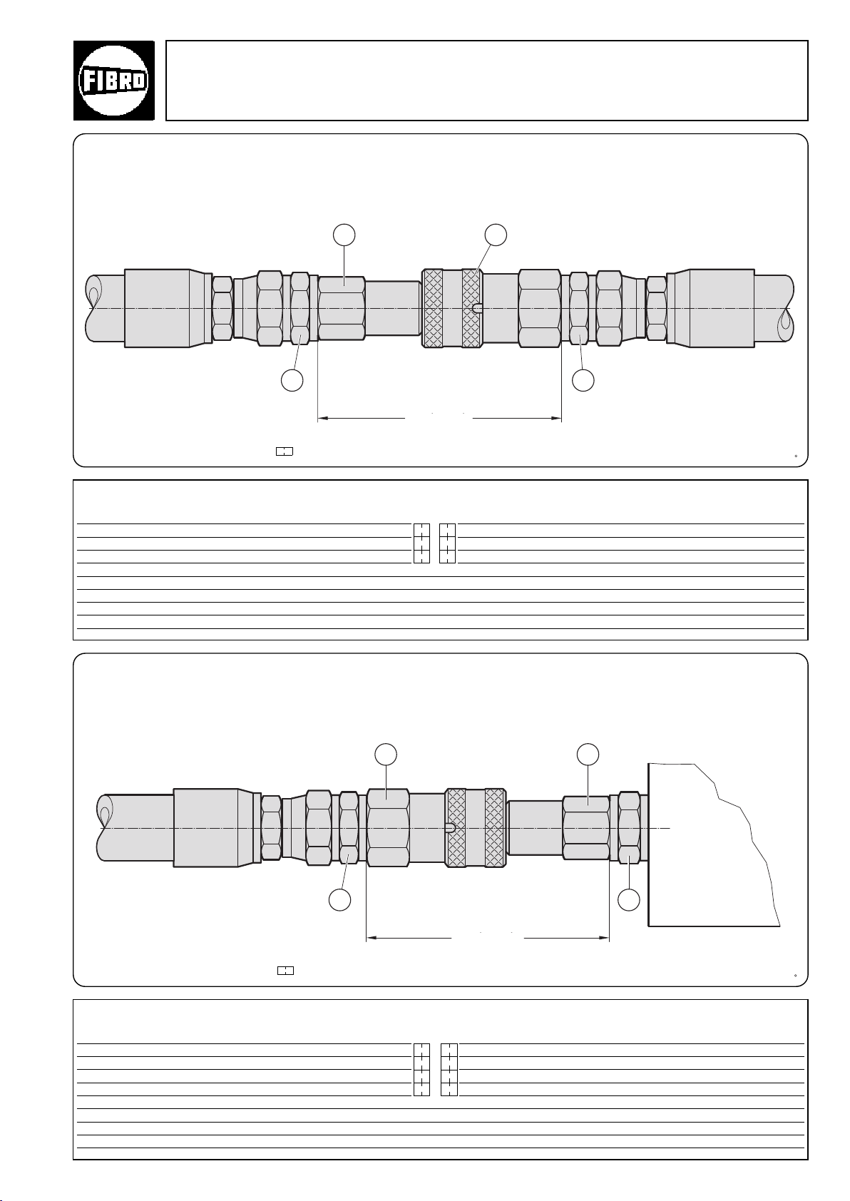
2018.00. Quick-release coupling
*l gekuppelt
3
1 2
3
*l gekuppelt
3
12
4
Quick-release coupling
Hose to hose
* For dimension I, see 2018.00.10.00. .1 or .2
Flex Cam
Accessories
coupled
2018.00.
Designation Number Order no. Comment
1 SK male connector 1 2018.00.10. . .1 Female/male connector size based on
2 SK female connector 1 2018.00.10. . .2 nominal hose size
3 Straight screw-in coupling 2 2018.00.21. . . Angled screw-in coupling could also be used
00000
0
0
Quick-release coupling
Hose to Power Unit and/or Cam Unit
coupled
* For dimension I, see 2018.00.10.00. .1 or .2
2018.00.
Designation Number Order no. Comment
1 SK male connector 1 2018.00.10. . .1 Female/male connector size based on
2 SK female connector 1 2018.00.10. . .1 nominal hose size
3 Straight screw-in coupling 1 2018.00.21. . .1 Angled screw-in coupling could also be used
4 SK screw-in coupling 1 2018.00.26. . .1 Nominal size based on Power Unit/Cam Unit size
°
2·14217·2001·2
subject to alterations
00
00
0
0
0
0
0
0
53
Page 56
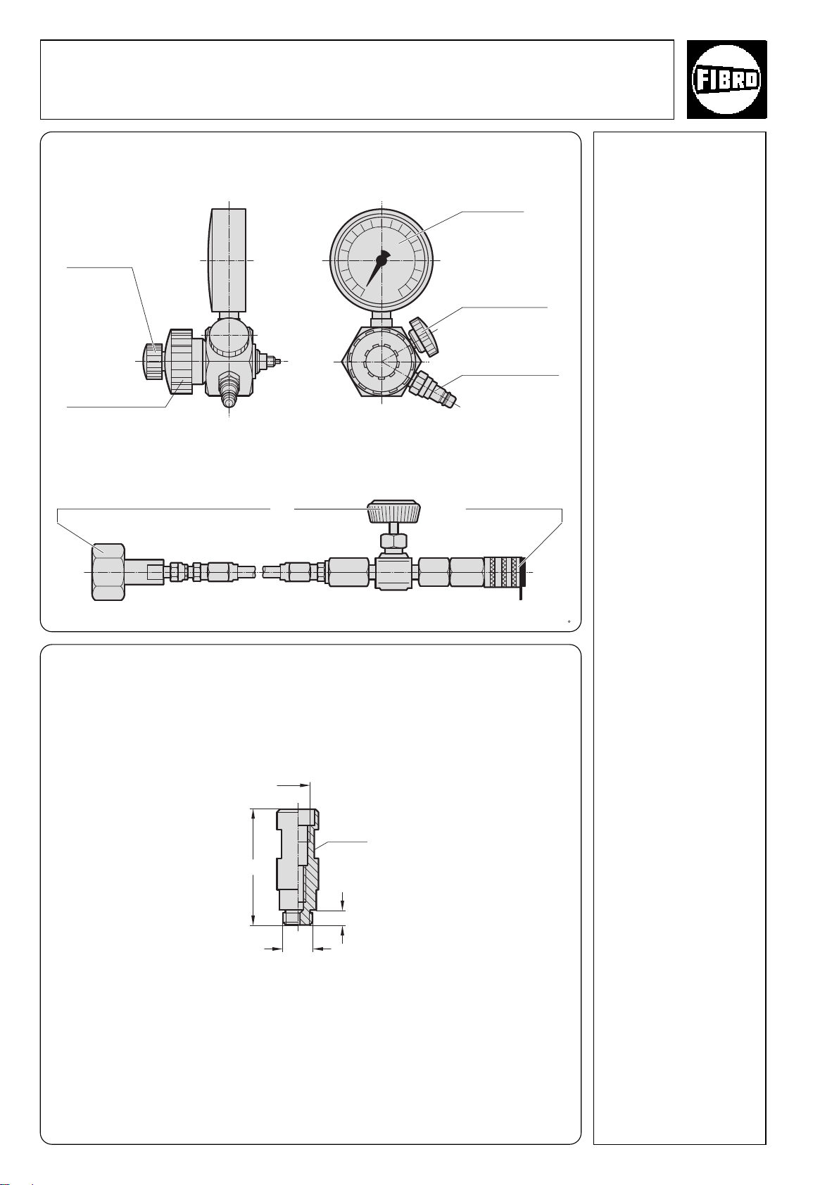
Flex Cam
1
/
8
G
M6
7
48
Accessories 2480.00.32.21
Filling and Control Fitting, Filling hose 2480.00.31.02
Charging Adapter 2480.00.32.11
2480.00.32.21 Filling and control fitting
Valve
actuation
Screw-on unit
for connection
to gas spring
2480.00.31.02 Filling hose
Coupling for gas cylinder or pressure
regulator Connector thread W 24,32 1/14
Shut-off valve
pressure
gauge
Gas spring
bleeder valve
Quick release
coupling – plug
connector
Quick release
coupling – socket
Description:
The filling and control
fitting 2480.00.32.21 is used
to fill, vary the pressure setting
(e.g. when testing tools) and
measure the gas pressure.
The coupling enables the
filling hose to be connected
directly to the gas cylinder
valve or the pressure regulator.
If the fitting is used solely for
checking purposes, a simplified arrangement not connected to the gas cylinder is also
possible.
Closing the shut-off valve of
the filling hose enables the
filling to be used to measure the charging pressure in
the accumulator / Cam Unit,
without detaching the hose.
For constant gas monitoring,
we recommend connecting a
control fitting 2480.00.30. or
2480.00.31.
The fitting is equipped as
standard with two adapters
2480.00.32.10/.11 for
connecting to various sizes
of coupling. (The adapter
required for charging both
Power Unit and Cam Unit is
2480.00.32.11).
2480.00.32.11
Charging adapter
Note:
2480.00.31.02 Filling hose
2 m long with quick release
coupling, shut-off valve and
gas bottle connector (order
separately).
Other filling hose lengths to
order.
AF 13
54
°
°
subject to alterations
2·14218·2005·3
Page 57
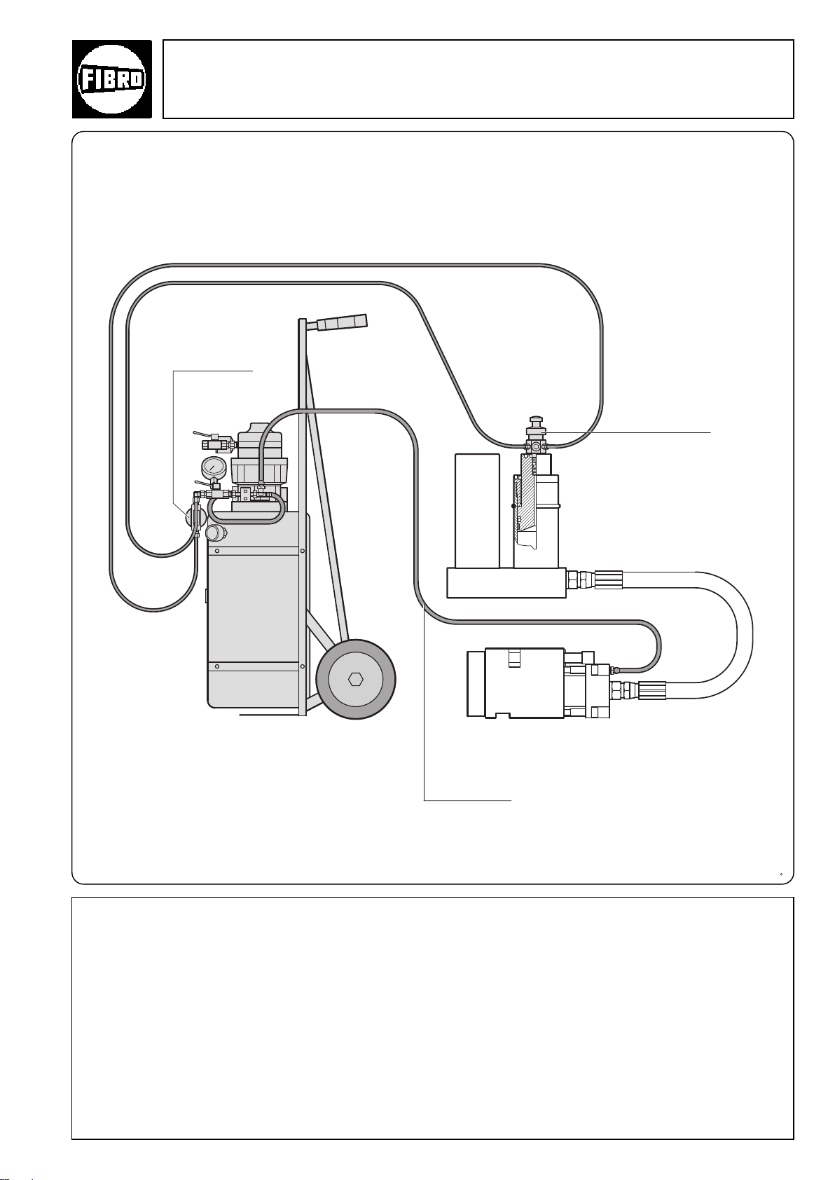
2018.00.30
Oil filling unit
Flex Cam
Accessories
2018.00.29 Oil filling unit
2018.00.30 Oil filling fitting
Filter for oil
filling unit
2018.00.30.01
Oil filling fitting
2018.00.29
Scope of supply:
Oil filling unit 2018.00.30
Filter 2018.00.30.01
°
Venting hose 2018.00.30.02
Oil filling fitting 2018.00.29
2·14219·2001·2
subject to alterations
Venting hose (3 m)
2018.00.30.02
Description:
The oil filling unit 2018.00.30 is used to fill the system with hydraulic
oil DIN 51524 HVLP ISO VG32.
Order no.: 280.37.032.05 ( 5 Liters) Hydraulic oil UNIVIS N 32
280.37.032.10 (10 Liters) Hydraulic oil UNIVIS N 32
280.37.032.50 (50 Liters) Hydraulic oil UNIVIS N 32
Precise instructions on filling the system with oil and gas are given in
The user manual supplied with the system.
55
Page 58
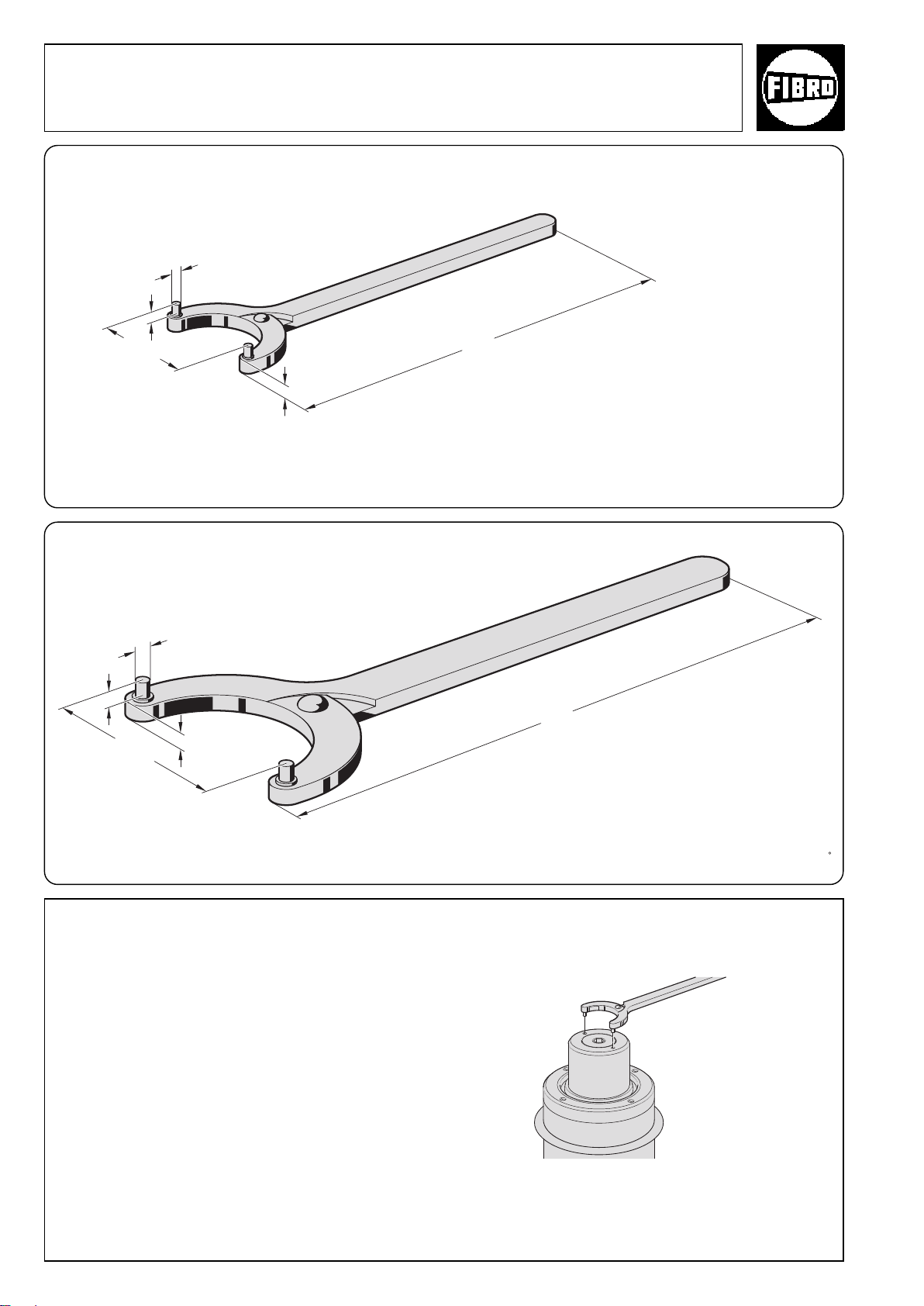
Flex Cam
150
5
4
18 - 40
3
220
6
6
40 - 80
5
Accessories 2018.00.20.1840.03
Assembly tools 2018.00.20.4080.05
2018.00.20.1840.03
Face wrench with adjustable
head for two-hole nuts
Used by Power Unit 2018.20.01500.
2018.20.04000.
2018.00.20.4080.05
Face wrench with adjustable
head for two-hole nuts
Used by Power Unit 2018.20.06000.
2018.20.09000.
2018.20.15000.
Material:
Special steel, burnished.
°
56
°
subject to alterations
°
2·14220·2001·2
Page 59
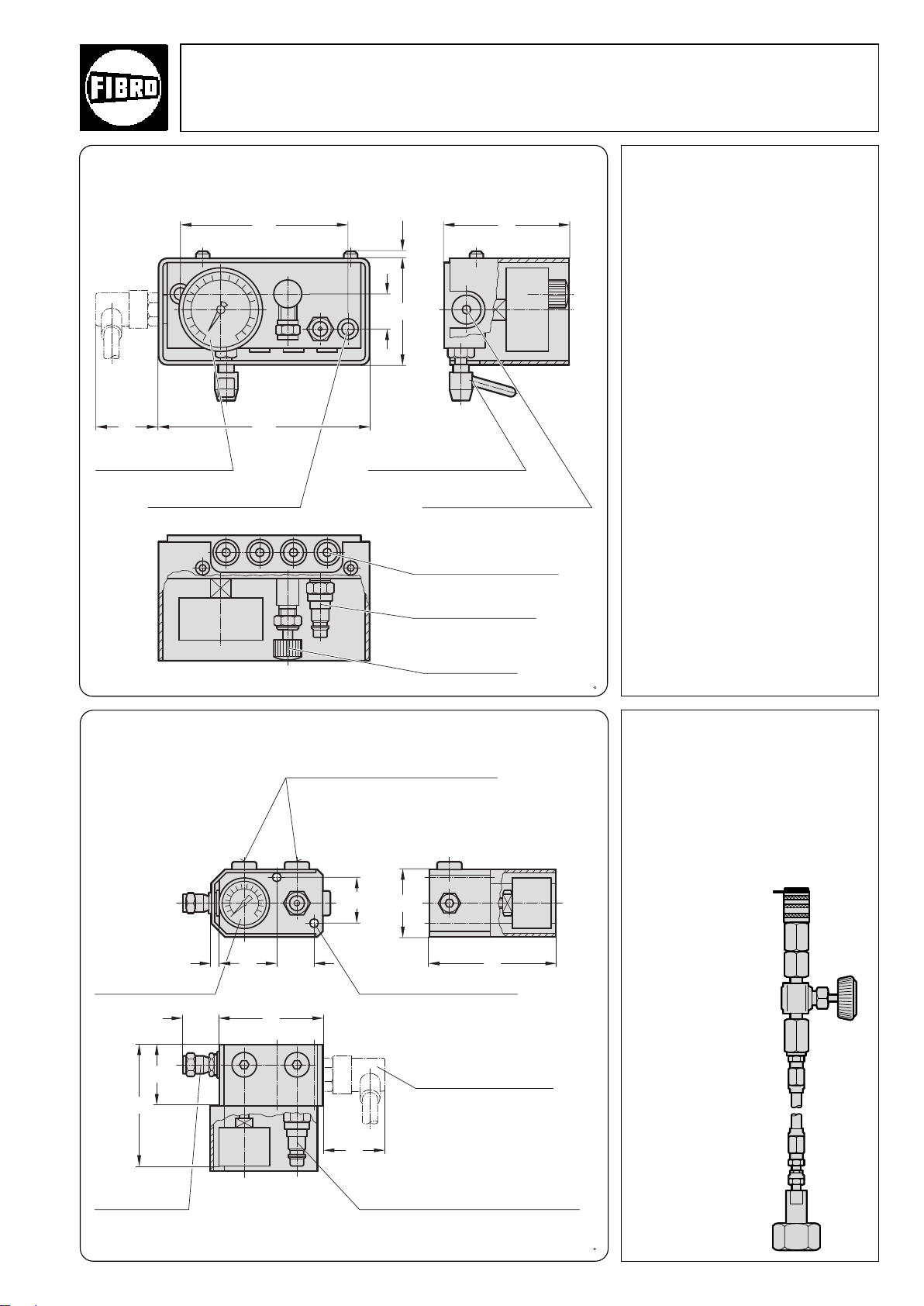
3,5
75
89
60 150
120
25
2480.00.30.01 Flex Cam
2480.00.30.03 Accessories
2480.00.31.01 Control Armature for Gas Springs
2480.00.30.01
2480.00.30.02
2480.00.30.03
2480.00.30.04
pressure gauge dial
fixing hole DIN 74 – Km 8
without pressure switch, without pressure relief
with pressure switch, without pressure relief
without pressure switch, with pressure relief
with pressure switch, with pressure relief
pressure gauge shut-off valve
connecting port for diaphragm
pressure valve 2480.00.45.01 or 02
connecting ports gas spring
Description:
The control armature 2480.00.30.01/03
serves to control the charge presure of
up to eight connected gas springs.
Pressure checks during operation can be
effected in two ways:
a) by visual monitoring of the gauge dials.
b) automatically, by means of diaphragm
pressure switch 248.00.15 The switch
will stop the associated machine as
soon as the charge pressure drops
below the value set.
Note:
The shut-off valve may be open or closed
during operation.
The closing of the pressure gauge shut-off
valve ensures that no pressure peaks from
the gas spring act on the pressure gauge.
* 2-m filler hose with rapid coupling
and connector for gas bottle
Order No. 2480.00.31.02
(to be ordered separately)
2480.00.31.01
pressure
gauge dial
6
26 75
rapid coupling nitrogen supply*
bleeder valve
Threaded connection for gauging coupling
2480.00.24.02 (see Page 60)
or diaphragm pressure switch 2480.00.45.01 or 02
(see Page 60)
50
9127
32
mounting holes Ø 7
Description:
The control armature 2480.00.31.01
performs the same function as the control
armature 2480.00.30.01.
Note:
* 2-m filler hose with rapid coupling and
connector for gas bottle 2480.00.31.02
(to be ordered separately)
bleeder valve
°
2·10075·9·3
subject to alterations
86
45
connecting port for diaphragm
pressure valve
2480.00.45.01 or .02
60
rapid closure coupling
nitrogen pressure supply*
°
57
Page 60
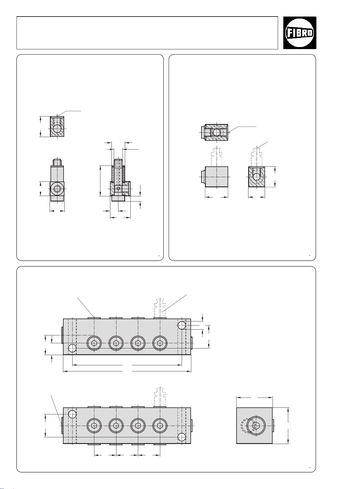
G1/4 (1x)
G1/8 (13x)
25
25 22
120
140
40
25
25 25
13
9
40
25
9,5
ø16
18
18 25
1
/8"
G
6,5
G
1
/8"
20
25
28
3 x G1/
8
Flex Cam
Compound Threaded Joints 2480.00.
2480.00.24.16 long
2480.00.24.17 short
2480.00.24.18 extra-long
Simple adapters for connecting Hydraulic Cams
24 short
38 long
48 extra long
2480.00.24.30
Coupling
Bleeder valve
2018.00.10.0017
2480.00.24.33
Distributor
Bleeder valve 2018.00.10.0017
°
58
2·14158·2001·2
subject to alterations
Page 61
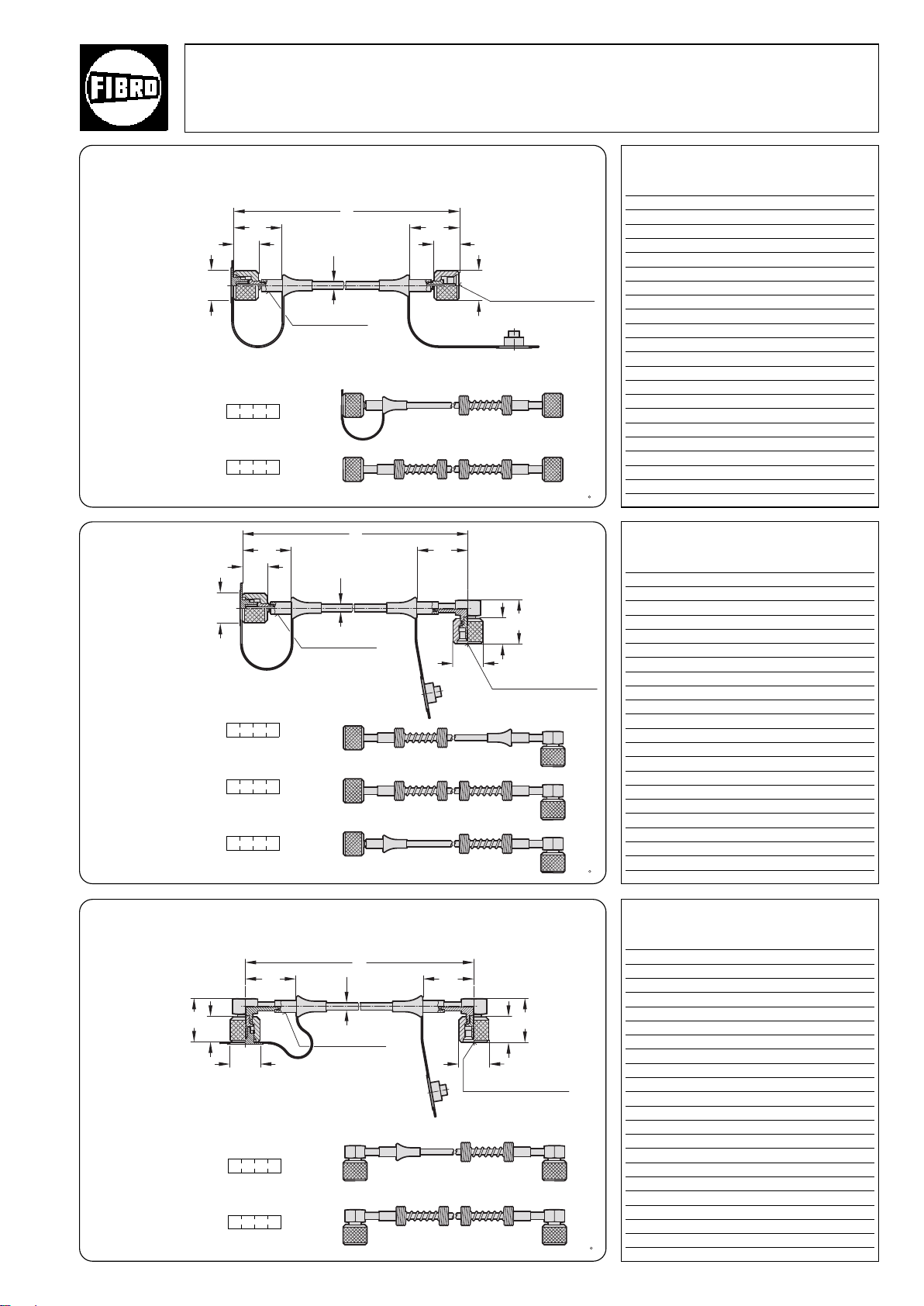
Flex Cam Accessories
ø20
ø5
ø20
17
3333
17
l*
ø20
17
29
ø5
ø20
17
29
4646
l*
ø5
ø20
ø20
17
29
17
33 46
l*
2480.00. Compound Threaded Joints
2480.00.23.01.
Gauging hose – both
ends straight
2480.00.23.01. .1
Antikink coil, at one end
2480.00.23.01. .2
Antikink coil, at both ends
2480.00.23.02.
Gauging hose – one
end straight 90°angle
2480.00.23.02. .1
Antikink coil, at one end, straight
2480.00.23.02. .2
Antikink coil, at both ends
Gripping sleeve
Gripping sleeve
Threaded
connection
S 12,65 x 1,5 (2x)
Threaded
connection
S 12,65 x 1,5 (2x)
2480.00.23.01.
Order No l*
2480.00.23.01.0200 200
0300 300
0400 400
0500 500
0630 630
0800 800
1000 1000
1200 1200
1500 1500
2000 2000
2500 2500
3000 3000
* other lengths available from 90 mm
upwards, in 5 mm steps.
without antikink protection : 90 mm
antikink protection at one end: 150 mm
antikink protection at both ends: 300 mm
2480.00.23.02.
Order No l*
2480.00.23.02.0200 200
0300 300
0400 400
0500 500
0630 630
0800 800
1000 1000
1200 1200
1500 1500
2000 2000
2500 2500
3000 3000
* other lengths available from 90 mm
upwards, in 5 mm steps.
without antikink protection : 90 mm
antikink protection at one end: 150 mm
antikink protection at both ends: 300 mm
2480.00.23.02. .3
Antikink coil at one end 90°
2480.00.23.03.
Gauging hose – both
ends
90°-angle
2480.00.23.03. .3
Antikink coil, at one end
°
2480.00.23.03. .2
Antikink coil, at both ends
2·14159·2001·2
subject to alterations
2480.00.23.03.
Gripping sleeve
Threaded
connection
S 12,65 x 1,5 (2x)
Order No l*
2480.00.23.03.0200 200
0300 300
0400 400
0500 500
0630 630
0800 800
1000 1000
1200 1200
1500 1500
2000 2000
2500 2500
3000 3000
* other lengths available from 105 mm
upwards, in 5 mm steps.
without antikink protection : 105 mm
antikink protection at one end: 150 mm
antikink protection at both ends: 300 mm
59
Page 62
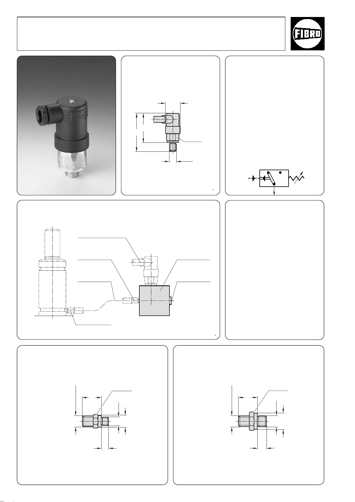
ø34
65
74
1
/
4
G
1
2
P
4
Flex Cam
1
/
8
G
ø14
8
22
S 12,65x1,5
ø19
10
21
1
/
4
G
S 12,65x1,5
Gas Spring Accessories 2480.00.24.
Diaphragm Pressure Switch/Gauging coupling 2480.00.45.
Installation Example:
diaphragm pressure
switch
2480.00.45.01
2480.00.45.02
connector
2480.00.24.02
2480.00.45.01 50-200 bar
for accumulator
2480.00.45.02 10-50 bar
for cam unit
A/F 27
adapter
2480.00.45.10
Technical Data of
Diaphragm Pressure
Switch
2480.00.45.01
switching range, adjustable 50–500 bar
switching tolerance ±3– 5 bar
overpressure protection 600 bar
switching frequency 200/min
voltage (max.) 250 V
2480.00.45.02
switching range, adjustable 10–50 bar
switching tolerance ±3,0 bar
overpressure protection 300 bar
switching frequency (max.) 200/min
voltage (max.) 250 V
Circuit diagram for
diaphragm pressure switch
°
hose
2480.00.23. ...
connector
2480.00.24.01
2480.00.24.01
Gauging coupling with valve for connection to
accumulator/cam unit
valve connecting
1
G
/
8
2480.00.24.02
Gauging coupling with valve for connection to control armature
A/F 14 A/F 19
60
subject to alterations
°
2·14160·2005·3
Page 63
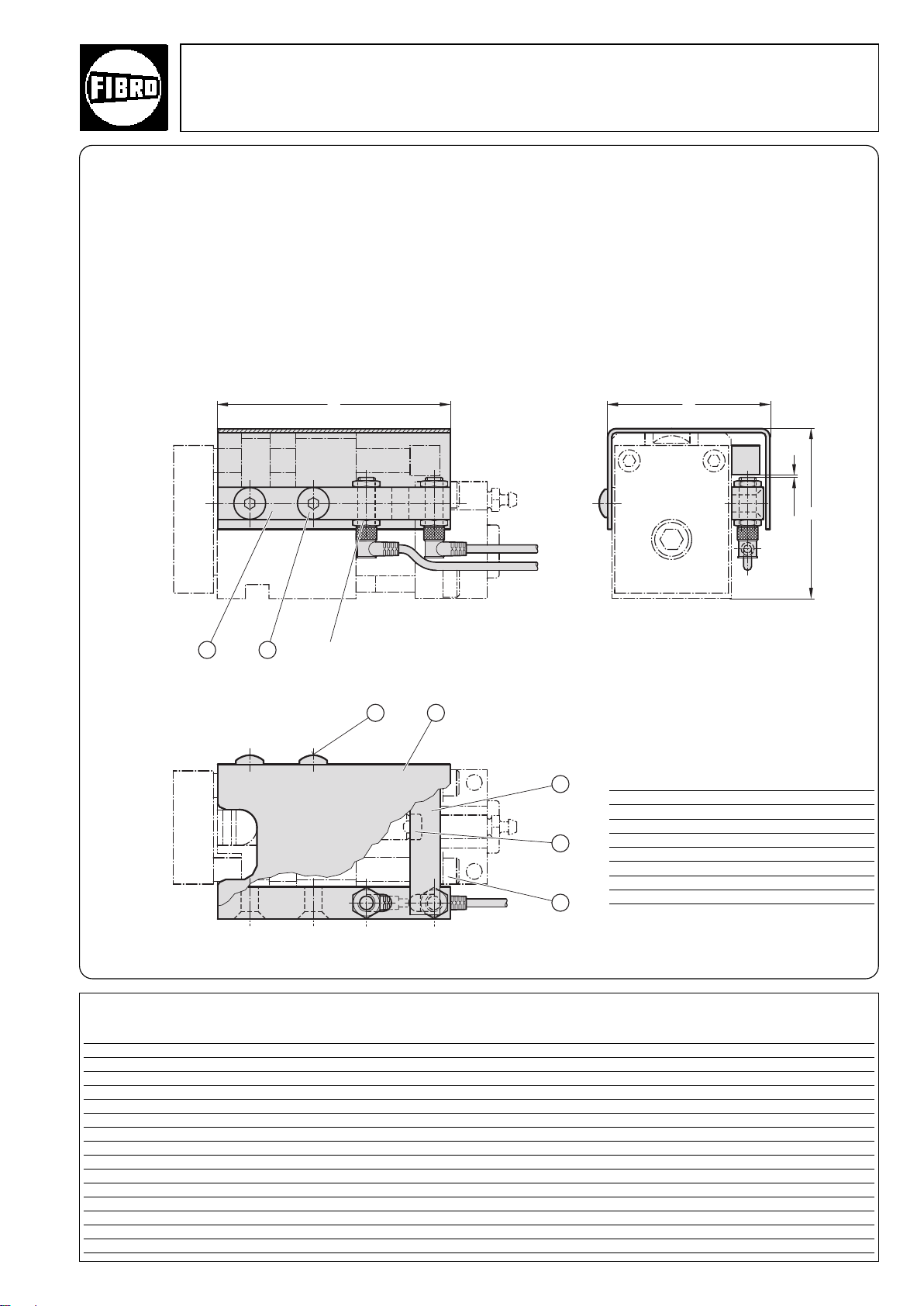
Flex Cam
3
5
4
12
76
l
2
l
1
l
0-1,2
2018.00.60. Accessories
2018.00.60.
Sensor mounting kit for Compact Cam 2018.11.
Description:
The sensor mounting kit with inductive proximity switch (order separately)
is used to monitor the end travel positions of the Compact Cam.
Both hub positions full extension and full retraction can be monitored.
The accuracy of adjustment is ±1 mm.
Inductive proximity switch
(order separately)
Order No e l
2018.00.60.01500.024 115 81 84
2018.00.60.01500.049 165 81 84
2018.00.60.04000.024 168 117 107
2018.00.60.01500.049 193 117 107
2018.00.60.01500.099 271 117 107
2018.00.60.06000.024 171 142 135
2018.00.60.01500.049 196 142 135
2018.00.60.01500.099 271 142 135
2018.00.60.09000.024 216 170 172
2018.00.60.01500.049 241 170 172
2018.00.60.01500.099 316 170 172
2018.00.60.15000.024 216 182 207
°
2018.00.60.01500.049 241 182 207
2018.00.60.01500.099 316 182 207
1
Mounting optional left or right
Item Designation Number
1 Mounting bracket 1
2 Screw 2
3 Activator flag 1
4 Centering washer* 1 oder 2
5 Screw 2
6 Cover plate 1
7 Screw 2
* not for 2018.11.09000.
l
2
For Compact Cam
2018.11.01500.024
2018.11.01500.049
2018.11.04000.024
2018.11.01500.049
2018.11.01500.099
2018.11.06000.024
2018.11.01500.049
2018.11.01500.099
2018.11.09000.024
2018.11.01500.049
2018.11.01500.099
2018.11.15000.024
2018.11.01500.049
2018.11.01500.099
2·16322·2001·1
subject to alterations
61
Page 64
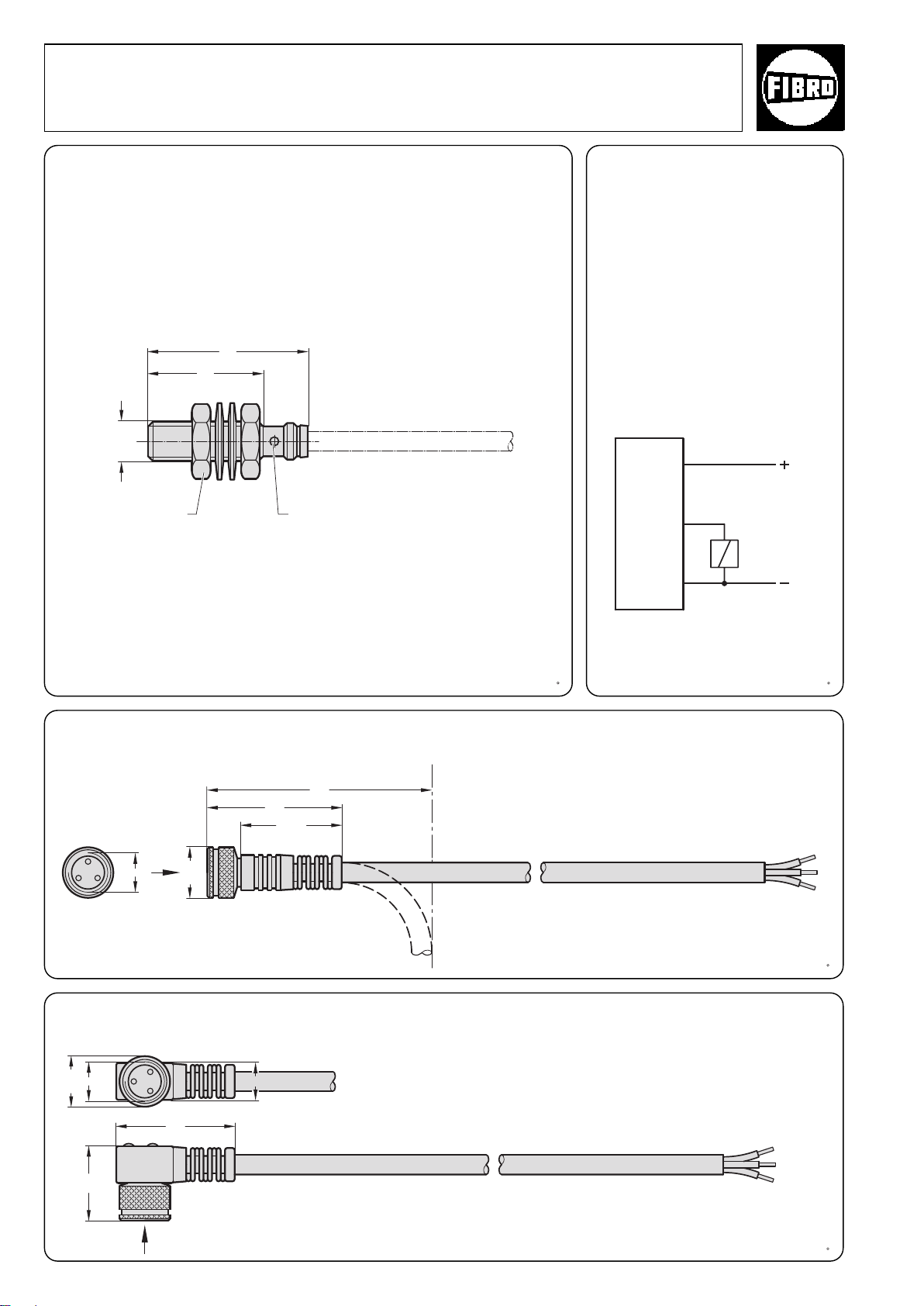
30
X
ø10
M8x1
22,5
40
M8x1
X
ø10
17
8
26
23
M8x1
32
LED
Flex Cam
Accessories
2018.00.60.08.032
Inductive proximity switch
A/F 13
Technical data
Rated operating
voltage U
Operating voltage Us 10-30 V DC
Idle current I
Damped/not damped ≤ 8 mA/≤ 1 mA
Repeat accuracy R ≤ 5%
Ambient temperature T
Switching frequency f 3000 Hz
Protection to IEC 529 IP 67
Casing material Steel
Connection Plug-in
Approval UL
e
o
Brown
Black
Blue
24 V DC
–40 to +85°C
a
stainless
connector
Load
2018.00.60.23.01.5 Connection cable – straight
Cable type: 3 pole M8, oil resistant
View X
Standard length 5 m. Other lengths upon request.
2018.00.60.23.02.5 Connection cable 90°
Cable type: 3 pole M8, oil resistant
Standard length 5 m. Other lengths upon request.
62
View X
°
2·16327·2001·1
subject to alterations
Page 65
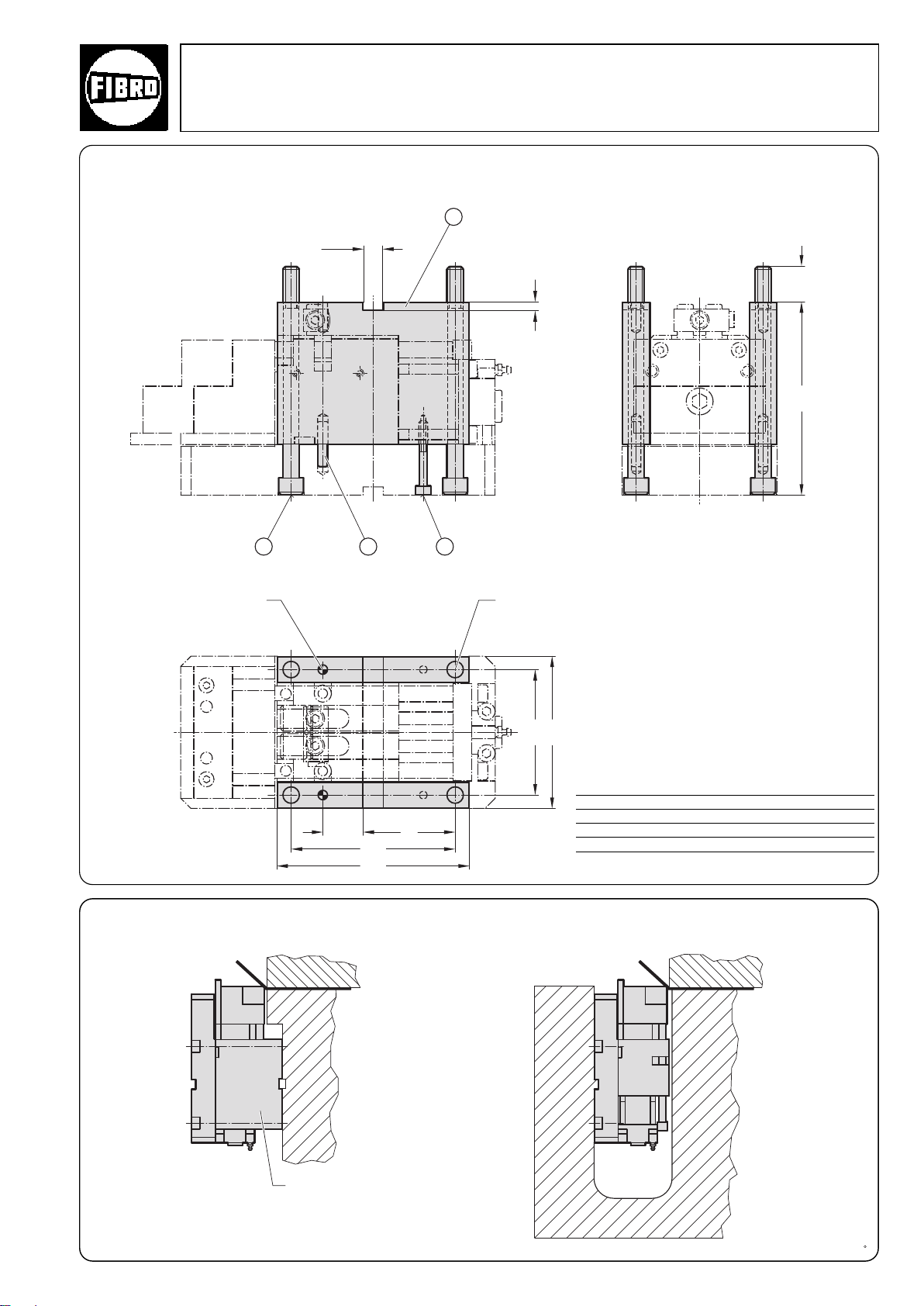
32
1
7
432
120
184
-0,015
39
+0,015
160
90
+0,02
20
186
145
2018.12.01.04000.049
Top mounting for Flange Cam
Flex Cam
Accessories
dowel pin 10 (2x)
Installation example for Flange Cam
Top mounting
fixing screw M16 (4x)
Item Designation Number
1 Spacer 2
2 M16200 Screw 4
3 1040 Dowel pin 2
4 Screw M860 2
Bottom mounting
°
°
2·16332·2001· 1
subject to alterations
Mounting kit
63
Page 66
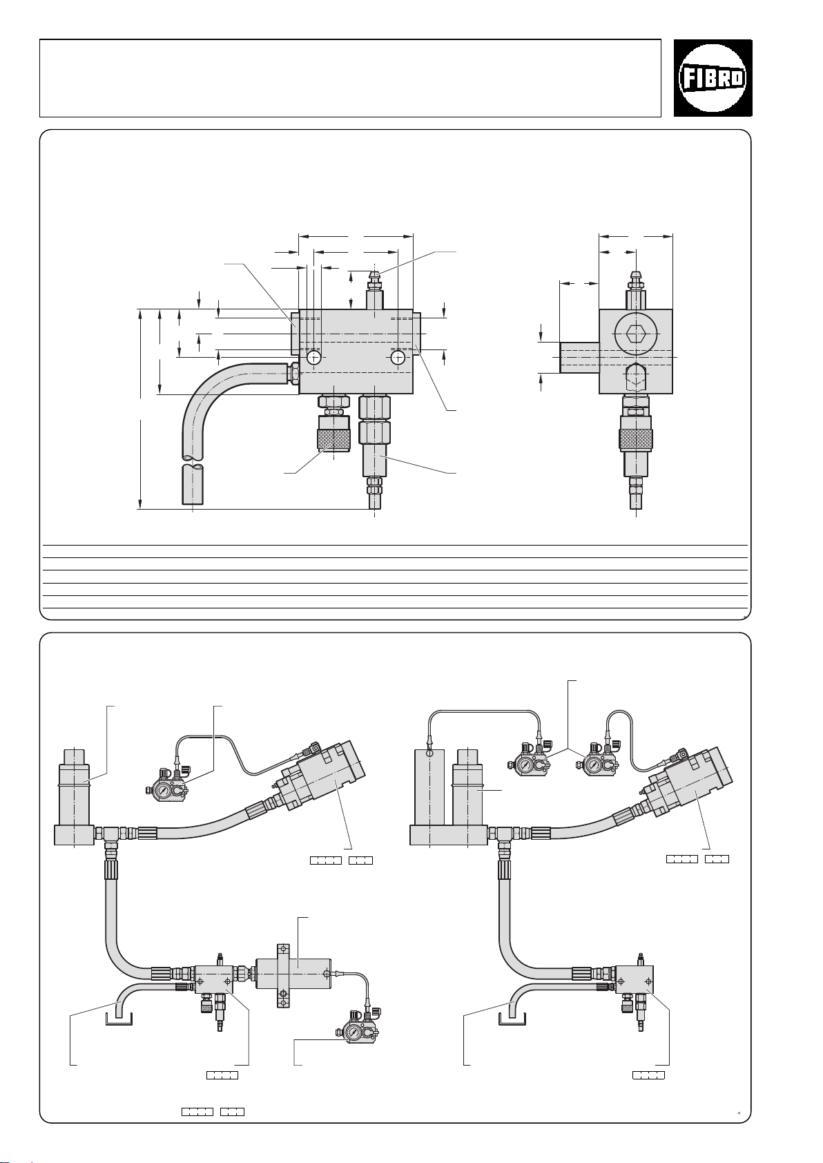
30
12,5
ø11(2x)
166
95
70
60
A
20
32
40
70
25
3
/
4
G
3
/
4
G
CNOMO E05.03.135.N
Flex Cam
Accessories 2018.27.01.
2018.27.01. Safety module
If a malfunction occurs in the primary unit, the system pressure can be released manually on the oil side via the discharge valve in the safety
module 2018.27.01.
A pressure limitation valve releases the oil pressure if the limit set is exceeded.
Connection for Cams Unit
and Power Unit
Discharge
valve
Order no. For Power Unit size 2018.25 A recommended nominal hose size
2018.27.01.01500 01500. 10 DN 12
2018.27.01.04000 04000. 22,5 DN 20
2018.27.01.06000 06000. 32,5 DN 25
2018.27.01.09000 09000. 44 DN 25
2018.27.01.15000 15000. 70 DN 32
Bleeder valve
Connection for
Accumulator
Pressure limitation
valve
Installation example for safety module
Power Cylinder
Drainage
hose
Use part number 2018.25. . to order Power Cylinder and Accumulator together.
64
Safety module
2018.27.01. fitted with
manual discharge valve and
pressure limitation valve.
Control fitting
2480.00.31.01
Compact Cam
2018.11. . .1
Accumulator
Control fitting
2480.00.31.01
Power Unit
Drainage hose
Control fitting
2480.00.31.01
Compact Cam
2018.11. . .1
Safety module
2018.27.01. fitted
with manual discharge valve
and pressure limitation valve.
°
2·16336·2001·1
subject to alterations
Page 67
Werkzeugbauer / Tool maker / Fabricant d'outillage
Tag der Erstinstallation /Date of first installation / Jour de la première installation
Werkzeugnummer / Tool number / Numéro d'outil
max. Hübe / strokes / Nombre de courses / min.
Type genutzter Hub (mm) / Anzahl der Einheiten / Fülldruck (bar) /
Stroke used (mm) / Number of units / Pressure (bar) /
Course utile (mm) Nombre d'unités Pression de remplissage (bars)
Gebereinheit /
Primary unit /
Unité maître cylindre
Nehmereinheit /
Secondary unit /
Unité cylindre récepteu
Type
Länge / Lenght / Longueur (mm)
Anzahl / Number / Nombre
Schlauchverbindungen /
Hose connections /
Liaisons par tuyaux flexibles
Achtung!
Hoher Druck / Vor Wartung und Arbeiten an dem Geber-Nehmer-System unbedingt Benutzerhandbuch lesen! /
Warning!
High pressure / ALWAYS read the User Manual before working on or with this flex cam system. /
Attention !
Haute pression Avant de procéder à l'entretien et d'effectuer des travaux sur le système maître cylindre/cylindre récepteur, lire absolument le manuel à l'usage de l'utilisateur !
FIBRO Geber-Nehmer-System / Flex Cam / Système maître-cylindre / cylindre récepteur
⊕
⊕ ⊕
⊕
FIBRO GmbH · DE-74851 Hassmersheim · Postfach 1120 · Made in Germany · Telefon ++49 (0)6266-73-0* · Telefon ++49 (0)6266-73-237
Flex Cam
2018.00.105.210. Safety label
We recommend that the safety warning should be located in a clearly visible position on the toll when
hydraulic cam systems are fitted.
Order no
Safety label = 2018.00.105.210.11100
°
To be applied to machines in which
hydraulic cam systems are fitted.
2·14161·2001·2
subject to alterations
65
Page 68

66
°
2·14166·2001·2
subject to alterations
Page 69

Flex Cam
Typical installations
for monitoring
process safety
°
2·14161·2001·2
subject to alterations
67
Page 70
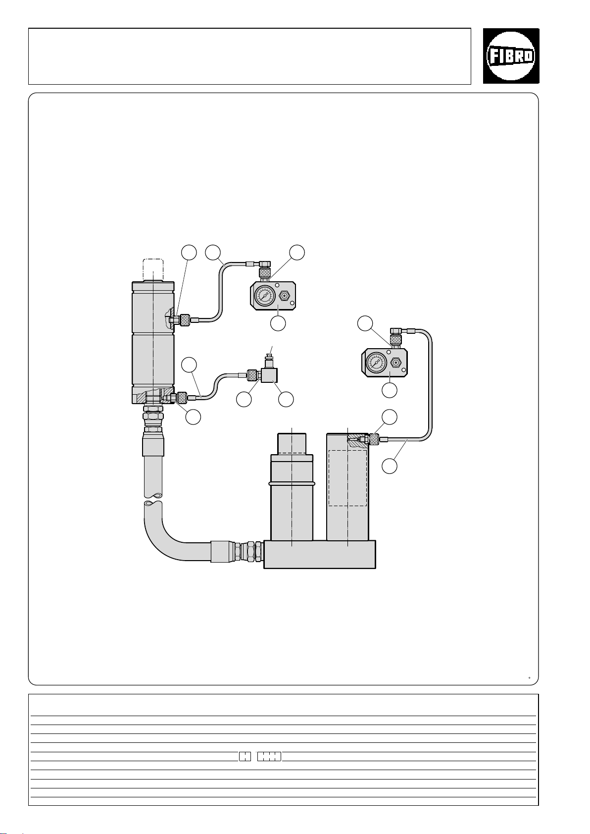
33
5
3
4
1
5
2018.10.0017 *
3
1
4
2
5
Flex Cam
Typical Installations
Monitoring Process Safety
Monitoring a Power Unit and a Cam Unit on the gas side
with external venting
* Screw the Cam Unit’s bleeder valve 2018.10.0017
into the coupling 2480.00.24.30.
Designation Number Order no. Comment
1 Control fitting 2 2480.00.31.01 Optionally with diaphragm-type pressure switch 2480.00.45.01 or 02
2 Coupling 1 2480.00.24.30
3Test coupling with valve 4 2480.00.24.01
4Test coupling with valve 2 2480.00.24.02
5Test hose 3 2480.00.23. . Type of connection and length as required
68
subject to alterations
°
2·14162·2001·2
Page 71
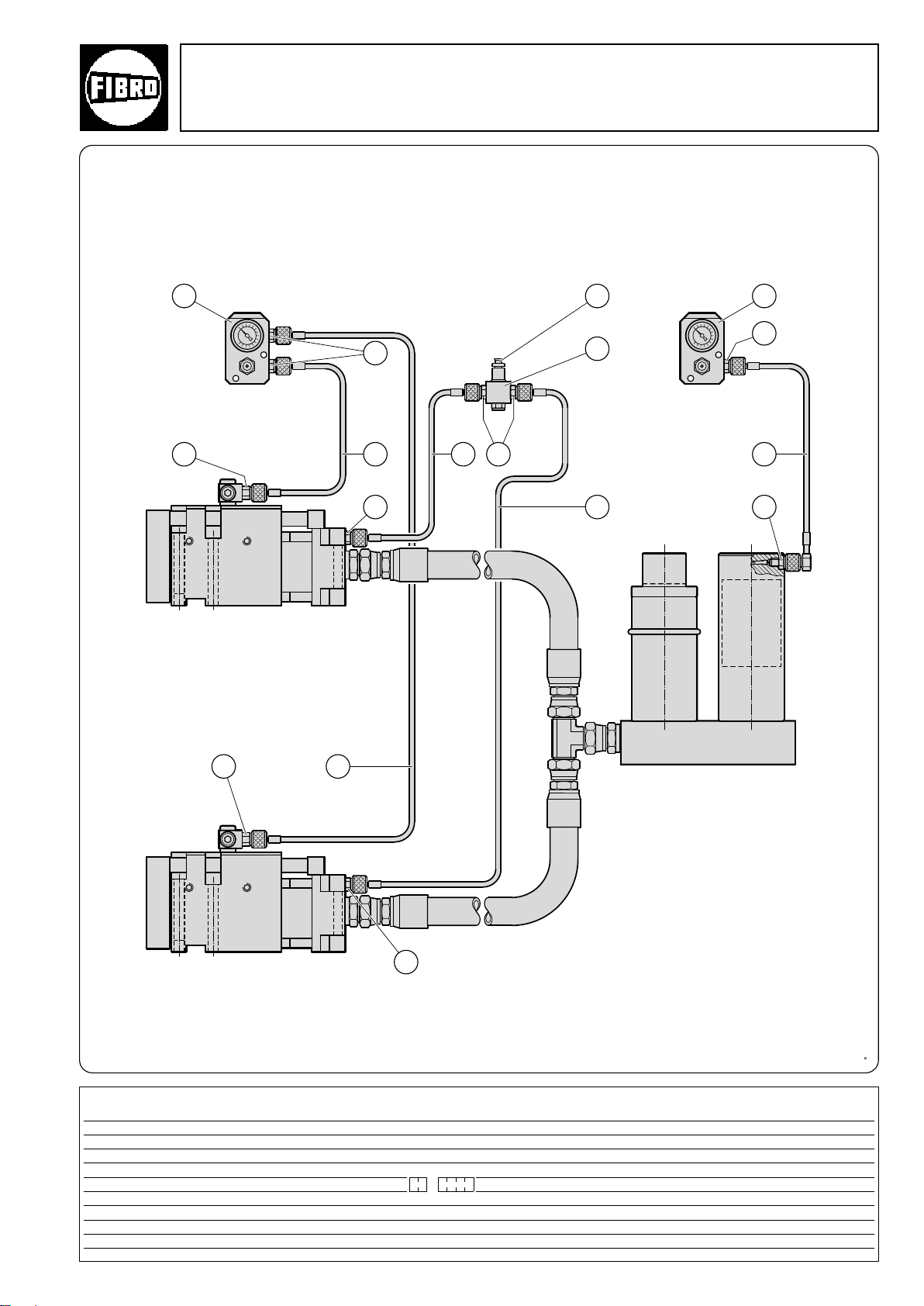
6
3
3
5
4
5
5
2
7
35
11
5
*
3
4
6
Flex Cam
Typical Installations
Monitoring Process Safety
Monitoring a Power Unit and two Cam Units on the gas side
with external venting
Asynchronous drive
*For Force Cylinder 2018.30 screw the bleeder valve 2018.100.0017 into the coupling 2480.00.24.30.
Designation Number Order no. Comment
1 Control fitting 2 2480.00.31.01 Optionally with diaphragm-type pressure switch 2480.00.45.01 or 02
2 Coupling 1 2480.00.24.30
3Test coupling with valve 5 2480.00.24.01
4Test coupling with valve 3 2480.00.24.02
5Test hose 5 2480.00.23. . Type of connection and length as required
6Test coupling with valve 2 2018.00.24.06
°
7 Bleeder valve 1 2018.10.0017
2·14163·2001·2
subject to alterations
69
Page 72
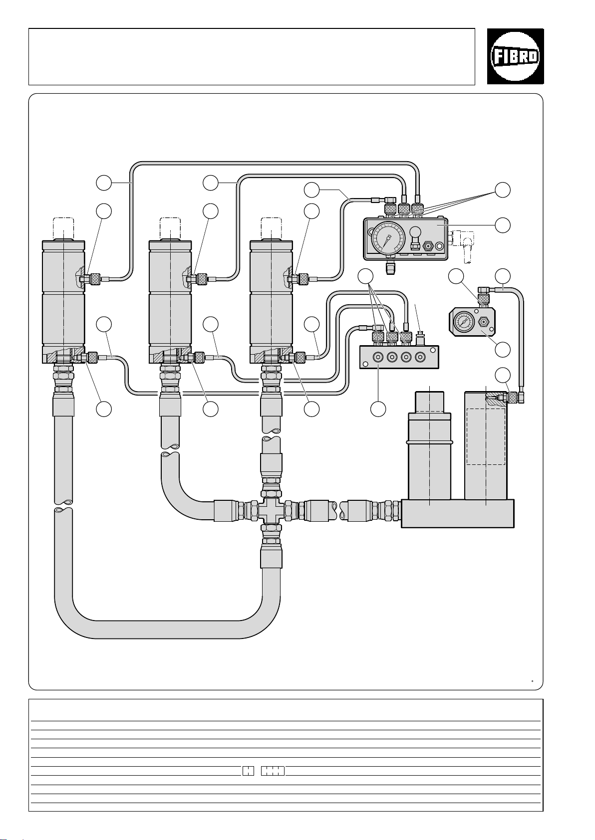
4
2018.10.0017*
1
4
65
2
5
6
4
6
6
4
6
4
6
4
6
44 3
Flex Cam
Typical Installations
Monitoring Process Safety
Monitoring a Power Unit and three Cam Units on the gas side
with external venting
Asynchronous drive
* Screw the Cam Unit’s bleeder valve 2018.10.0017
into the coupling 2480.00.24.30.
Designation Designation Designation Comment
1 Control fitting 1 2480.00.31.01 Optionally with diaphragm-type pressure switch 2480.00.45.01
2 Control fitting 1 2480.00.30.01 Optionally with diaphragm-type pressure switch 2480.00.45.02
3 Distributor box 1 2480.00.24.33
4Test coupling with valve 10 2480.00.24.01
5Test coupling with valve 4 2480.00.24.02
6Test hose 7 2480.00.23. . Type of connection and length as required
70
subject to alterations
°
2·14164·2001·2
Page 73
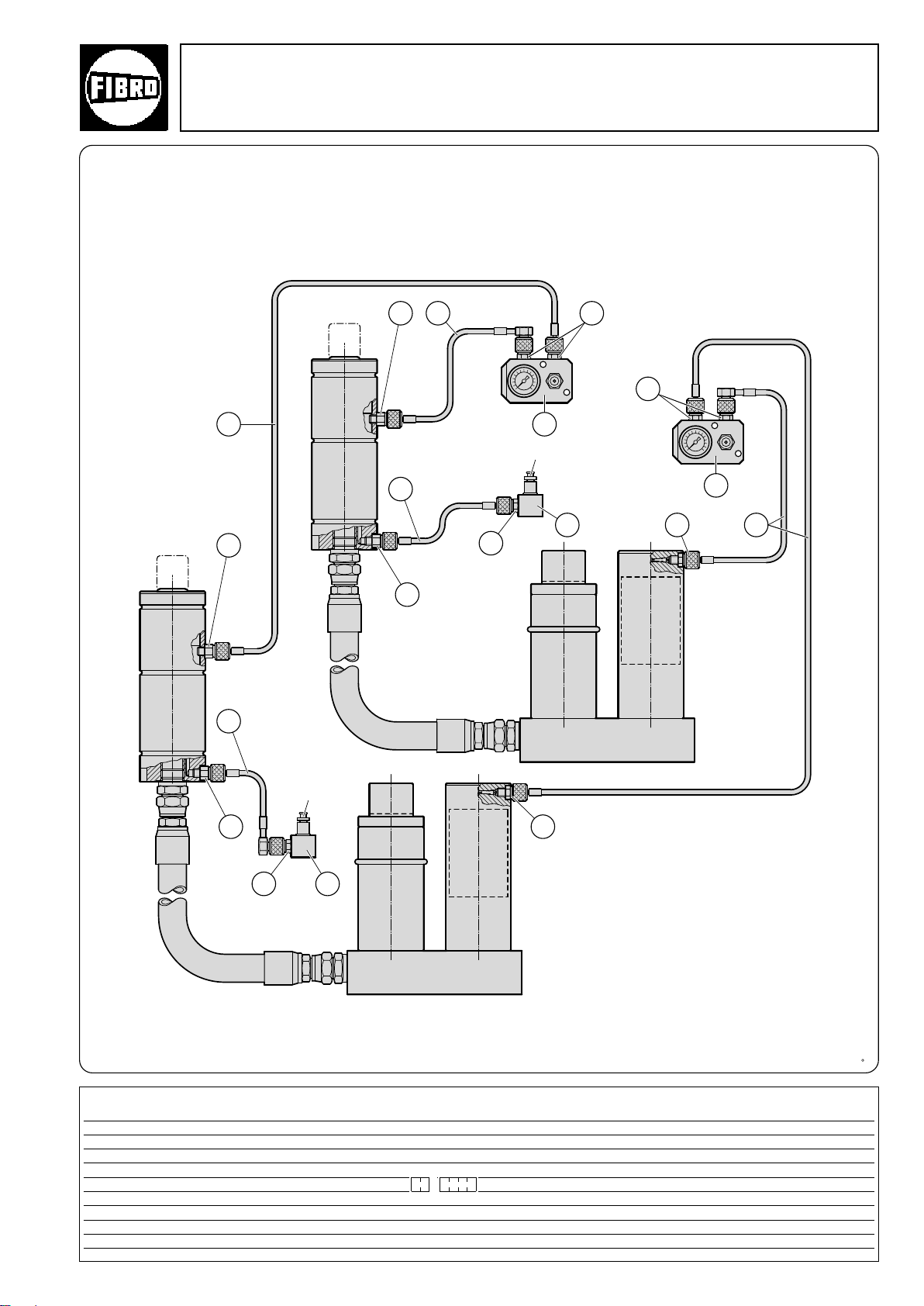
53
3
4
5
3
1
1
5
3
5
3
4
5
3
2018.10.0017*
2018.10.0017*
3 2
3
2
Flex Cam
Typical Installations
Monitoring Process Safety
Monitoring two Power Units and two Cam Units on the gas side
with external venting
Synchronous drive
* Screw the Cam Unit’s bleeder valve 2018.10.0017
Designation Designation Designation Comment
1 Control fitting 2 2480.00.31.01 Optionally with diaphragm-type pressure switch 2480.00.45.01 or 02
2 Coupling 2 2480.00.24.30
3Test coupling with valve 8 2480.00.24.01
4Test coupling with valve 4 2480.00.24.02
5Test hose 6 2480.00.23. . Type of connection and length as required
°
2·14165·2001·2
subject to alterations
into the coupling 2480.00.24.30.
71
Page 74

72
°
2·14166·2001·2
subject to alterations
Page 75

Flex Cam
Typical Applications
°
2·14167·2001·2
subject to alterations
73
Page 76
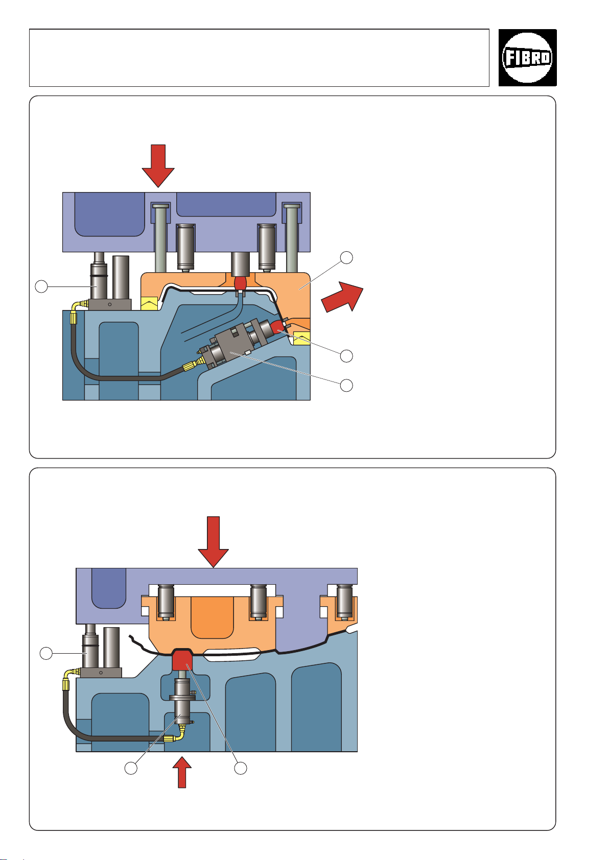
Flex Cam
4
1
2
3
2
3
1
Typical Applications
Application: Cutting with Compact Cam
Press stroke
Cutting direction
This example shows how a compact cam (1) can be used for punching holes. The punch can be
mounted directly to the Compact
Cam, which means that no additional guides are required in the
tool. The diagram shows that the
Power Unit does not have to be
installed in the vicinity of the Cam
Unit, making it much more flexible
compared to conventional mechanical systems. We recommend fitting a stripping unit (2) to the
punch.
Working sequence
When the top part of the tool moves
down, it actuates the clamping
pad (3) that holds the workpiece in
position. The clamping pad is
centred with respect to the bottom
part of the tool by conical spacers.
Once the clamping pad reaches its
position, the Power Unit is actuated (4) and the Cam Unit executes
its operation.
Application: Metal forming
Press stroke
°
This example shows how one or
more Cam Units (1) can be used to
drive embossing punches (2)
(or tool slides) in a machine tool.
The punch (or slide) is guided in
the tool. This method of driving
tool components allows considerable flexibility in the machine tool
layout. The Cam Unit only generates the motion and force.
Only shearing and tensile forces
are permitted.
Working sequence
As the top part of the tool moves
down, it actuates the clamping
pad that holds the workpiece in
position. When the clamping pad
reaches its position, the Power
Unit is actuated (3) and the Cam
Unit executes its operation. The
embossing force can be adjusted,
if necessary, by varying the
pressure in the Accumulator.
74
Drawing direction of the
Force Cylinder
subject to alterations
°
°
2·14168·2001·2
Page 77
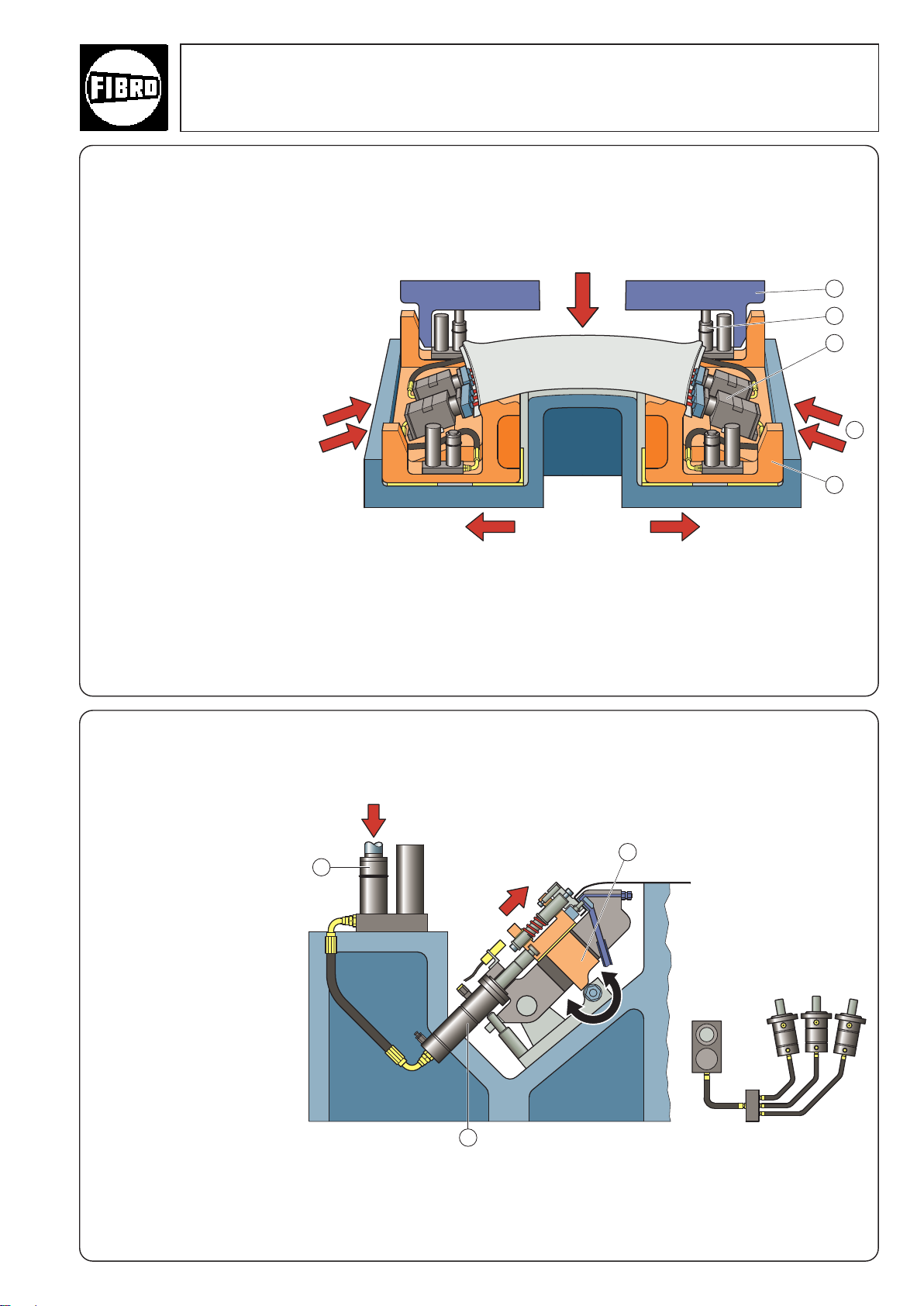
Flex Cam
1
2
3
2
5
1
4
3
Typical Applications
12 holes are punched at a
negative angle (1). In this tool,
the Flex Cam is equipped with
mechanically-driven filling
slides (2).
Working sequence:
The filling slide (2) is first moved
into position, controlled by the
overflow wedge (3). As the
press descends further, the four
Power Units (4) are pressurised, causing the Cam Units (5)
to punch the holes. In this
arrangement, the hole punching operation requires no
other drivers, which means
that it can easily be performed
at an angle of 90° to the workpiece.
Application: Cutting with positioning of the overflow wedge
Press stroke
Cutting
direction
Driving pad directionDriving pad direction
Cutting
direction
6 holes are punched at a
negative angle using working
cylinders that drive a shearing
punch unit (1).
Working sequence:
The diagram shows the Flex
Cam in its end position (press
at bottom dead centre). As the
working cylinder (2) starts to
move back, the punch moves
out of the punching area. The
entire shearing punch then
swivels down so that the workpiece can be removed. The
operation is reversed when the
top part of the press down
descends once more. The tool
contains two systems: one on
the left and the other on the
right. Each system consists of
a Power Unit (3) that drives
three Cam Units.
Press stroke
Application: Punching holes with a swivelling die
Swivelling stroke
°
°
2·14169·2001·2
subject to alterations
°
75
Page 78
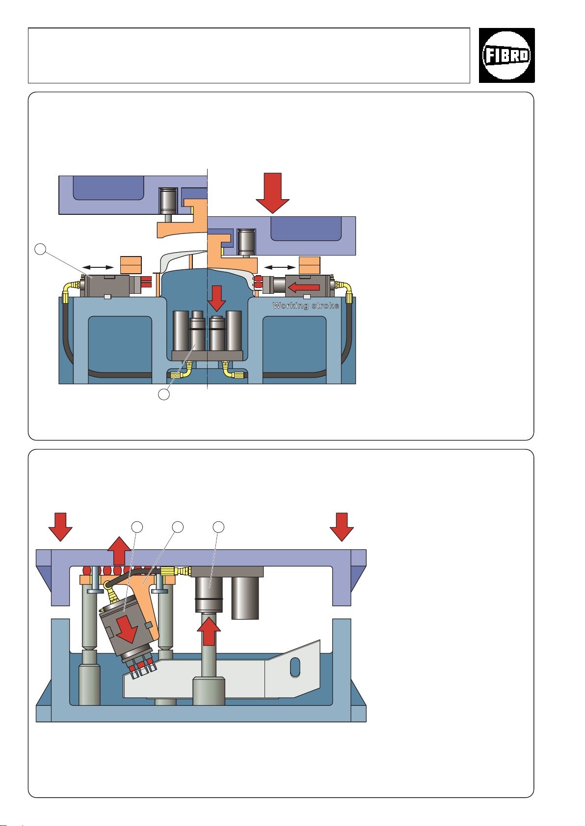
1
2
Flex Cam
1 2 3
Typical Applications
Application: Punching holes with a Flex Cam
Stroke ratio 1:2.5
Transfer unit
Press stroke
This tool produces two workpieces at the same time: one on the
right and the other on the left. On
the left-hand side of the diagram,
the press is at the top dead centre
position. On the right-hand side,
the press is at the bottom dead
centre. The transport grippers can
be seen above the Cam Units.
The workpiece must be shaped
before the holes are punched in
the sides.
The machining contour requires a
relatively large distance between
the blank and the punching unit.
Working sequence:
A small Cam Unit (1) is connected
to a larger Power Unit (2) in order
to guarantee the necessary
time/traverse sequence. This
results in a stroke ratio of 1 to 2.5.
Example: If the Power Unit stroke
is 10 mm, then the Cam Unit stroke will be 25 mm.
Application: Cutting with floating suspension and conical
spacers
°
This application uses a Flex Cam
that is suspended from above (in
the top part of the tool).
Working sequence:
The Cam Unit (1) is mounted on a
floating die (2). The floating die is
spring-mounted and is centred
with respect to the bottom part of
the tool by conical spacers. As the
press moves down and the floating
die is centred, the Power Unit (3) is
activated and the holes are
punched.
Before the Flex Cam was installed,
the holes were punched vertically
using oval forming punches.
Due to the improved production
output and quality that resulted
from installing the Flex Cam, the
system paid for itself (including
installation) within just three
months.
76
°
°
2·14234·2001·2
subject to alterations
Page 79
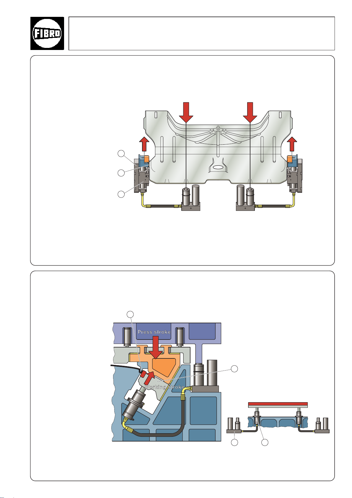
2
1
3
Flex Cam
2 3
1
4
Typical Applications
The diagram shows a base
plate which is used in the
Flex Cam (1) to cant (bend
up) lateral tabs (2).
Working sequence:
The bending punches fixed
to the Cam Units (in this case
Flange Cams) are supported
at the sides (3). These supports absorb the severe lateral forces resulting from the
bending operation.
Without this system, it would
have been necessary to produce an entire new tool with
a floating die or to introduce
a second operation.
Slide
direction
Flange
Cam
Application: Bending
Press stroke
Slide
direction
Flange
Cam
Driving
unit
This tool has two Force
Cylinders for driving an
800 mm wide bending
punch.
Working sequence:
As can be seen from the
diagram, the blank is bent
(1) at an angle, against the
motion of the press.
Two separate Flex Cam to
synchronise the motion of
the bending punch. Each
system consists of a Power
Unit (2) and a Force Cylinder
(3).
The bending punch (4) is
guided in the tool. As a
result, the Force Cylinders
only absorb axial forces.
Use of the Flex Cam simplified the structure of this
tool, thus reducing the
machinery costs.
°
Application: Bending –
slide driven synchronously
°
2·14256·2001·2
subject to alterations
°
77
Page 80

Weibertreu
Castle at Weinsberg
Indexing tables
FIBRO works at Weinsberg
FIBRO – The latest technology – with a tradition of service
The FIBRO of today started up in Weinsberg on a very
small scale back in 1958. Situated below the historic
Weibertreu Castle, the company made precision ground
round parts, the forerunners of today’s FIBRO Standard
Parts range for the toolmaking industry.
Progress was rapid and soon FIBRO needed new
production facilities. A new factory was built at
Hassmersheim on the River Neckar. Once again it was
a historic location, this time opposite Hornberg Castle.
Indexing tables
From 1962 onwards FIBRO at Weinsberg pioneered the
design and manufacture of indexing tables and soon
gained an enviable reputation.
FIBROTAKT: indexing tables with face gear and ultrahigh-precision indexing, combined with dependable
rigidity. Drive options: pneumatic, hydraulic, electric.
Rotation by rack and pinion or worm drive. Manual or
NC control.
FIBROPLAN: indexing tables with worm drive and NC
indexing and drive, for circular milling and divisions of
any size.
FIBROTOR: revolving tables or indexing tables with
positive-drive cam, offering very short cycle times even
when transporting heavy loads. Suitable for automation
with short cycle times. Thousands of FIBRO units are in
use world-wide as integral key components in highoutput machinery.
78
Standard Parts
Today the Standard Parts division operates from
the Hassmersheim works which manufactures a
comprehensive range of standard parts and maintains
stocks ready for immediate despatch world-wide.
The machine tool, mechanical engineering and systems
engineering product range includes machine pillars,
guide rails, oilless guide elements and precision parts
such as cutting dies and die bushes, special steel
pressure springs, gas springs, forming materials, metal
bonding agents and moulding resins, accessories for
pressing and toolmaking, tool slides with cam or roller
drives and independent hydraulic drives.
FIBRO has become renowned world-wide for its
comprehensive range of products kept in stock and its
readiness to deliver.
°
0·17774·2002 ·1
subject to alterations
Page 81

Hornberg castle on the opposite side of
the river
Standard Parts
Automation+Robotics
Automation+Robotics
FIBRO has been active in the field of automation and
robotics since 1974 from the Hassmersheim works.
Modular construction based on translation units, rotary
units, grippers and guide gantries with trolleys make for
easy construction of individual machines and complete
systems, ranging from simple pick & place units right
through to multi-axis robots. These series-manufactured modules are available in several sizes for loads up
to 3150 kg, traversing speeds up to 6.5 m/sec and
travel of up to 30 m. Module series with electric-motor,
hydraulic and pneumatic drive can be combined to suit
the specific requirements. The system has a track
record of success in many sectors of industry.
The FIBRO Hassmersheim plant
FIBRO: a company with a great history. FIBRO has
developed at a rapid pace in these fast-moving times
and will continue to demonstrate its proactive philosophy in the future.
FIBRO – precision technology for the toughest tasks.
More about FIBRO:
• 900 staff;
• 80 representatives and service stations world-wide;
• branch offices in France, USA, Singapore
and Switzerland.
FIBRO is much in demand as a supplier to the
mechanical engineering and metalworking sectors.
This success is based largely on three factors: FIBRO’s
in-depth knowledge of the market, its commitment to
quality assurance in line with ISO 9001 and its flexible
and responsive organisational structure so typical of
medium-sized German companies.
°
0·17775 ·2002·1
subject to alterations
79
Page 82

Vertretungen
Representatives
Représentations
Rappresentantes
Representaciones
FIBRO GmbH
[email protected] · www.fibro.com
Normalien
Standard Parts · Éléments normalisés
1
Normalizzati · Elementos normalizados
Postfach 1120 · DE-74851 Hassmersheim
August-Laepple-Weg · DE-74855 Hassmersheim
Tel. +49(0)6266-73-0*· Fax +49(0)6266-73-237
Rundschalttische
Indexing Tables · Plateaux diviseurs
2
Tavole rotanti · Mesas divisoras
Postfach 1120 · DE-74183 Weinsberg
Weidachstrasse 41-43 · DE-74189 Weinsberg
Tel. +49(0)7134-73-0*· Fax +49(0)7134-73-120
[email protected] · www.fibro-gsa.com
Automation
Automation · Automatisme
3
Automazione · Automatismos
Postfach 1120 · DE-74851 Hassmersheim
August-Laepple-Weg · DE-74855 Hassmersheim
Tel. +49(0)6266-73-0*· Fax +49(0)6266-73-213
Postfach 1165 · DE-74173 Bad Friedrichshall
Max-Eyth-Strasse 7 · DE-74177 Bad Friedrichshall
Tel. +49(0)7136-9502-0 · Fax +49(0)7136-9502-240
DE
123 Heinrich Siggel GmbH
PLZ 10000-16000
123 Walter Ruff GmbH
PLZ 21000-29000, 49000
23 Außendienst Karl-Heinz Keßler
PLZ 30000-34000, 37000, 38000
1 Außendienst Jörg Dyck
PLZ 06000, 29000-31000, 37000-39000
1 Oltrogge & Co.
PLZ 33000
1 Schwab GmbH
PLZ 35000
23 Ing. Büro für Automation Dirk Ahke VDI
PLZ 40000-48000, 50000-53000, 56000-59000
1 Außendienst Lars Jahncke
PLZ 40000-48000
1 Außendienst Hartwig Hennemann
PLZ 40000-42000, 50000-53000
1
PLZ 57000
1
PLZ 58000
3 Schlegel & Volk KG
PLZ 60000
1 Außendienst Volker Hottes
PLZ 53000-56900, 60000-66900
23 Außendienst Guido Steinbrück
PLZ 55000, 35000+36000, 60000-68000, 76000
Waldstraße 1 · 14163 Berlin
Tel. 030-802 90 13 · Fax 030-802 90 14
[email protected]
Postfach 450118 · 28295 Bremen
Heerenholz 9 · 28307 Bremen
Tel. 0421- 438 78-0 · Fax 0421-438 78-22
[email protected] · www.praeziruff.de
Mehlstraße 8 · 33729 Bielefeld
Tel. 0521-764 43 · Fax 0521-770 75 58
Mobil 0170-564 34 15 · [email protected]
Richard-Wagner-Straße 5 · 31171 Nordstemmen
Tel. 0421- 43 81 80 · Fax 05069-51 65 31
Mobil 0172-568 84 32 · [email protected]
Postfach 102093 · 33520 Bielefeld
Finkenstraße 61 · 33609 Bielefeld
Tel. 0521-32 08-0 · Fax 0521-32 08-129
[email protected] · www.oltrogge.de
Postfach 1209 · 35323 Mücke
Bergwiesenstraße 10 · 35325 Mücke
Tel. 06400-80 11 · Fax 06400-80 12
Zum Wenzelnberg 2a · 40764 Langenfeld
Tel. 02173-270 41-0 · Fax 02173-270 41-30
[email protected]
Flockertsberg 17 · 42653 Solingen
Tel. 0212-254 34 62 · Fax 0212-254 33 90
Mobil 0170-763 71 25 · [email protected]
Staubenthaler Höhe 79
42369 Wuppertal
Tel. 0202-283 17 56 · Fax 0202-759 55 80
Mobil 0175-296 59 30 · [email protected]
Normalien-Zentrale-Siegerland Bernd Kreitzberg
Postfach 1132 · 57225 Wilnsdorf
Rudersdorfer Straße 18 · 57234 Wilnsdorf
Tel. 02739-25 44 · Fax 02739-41 16
Mobil-Tel. 0170-274 27 95
[email protected] · www.kreitzberg.de
Stahlschmidt Industriebedarf u. -vertretungen
Postfach 65 · 58846 Herscheid
Eichenweg 12 · 58849 Herscheid
Tel. 02357-30 99 · Fax 02357-22 55
Mobil-Tel. 0171-642 57 97
[email protected]
www.stahlschmidt-industrievertretung.de
Ditmarstraße 7 · 60487 Frankfurt
Tel. 069-970 61 30 · Fax 069-707 14 69
[email protected] · www.schlevo.de
Erzberger Straße 1 · 64846 Groß-Zimmern
Tel. 06071-39 21 19 · Fax 06071-39 21 45
Mobil 0171-957 79 89 · [email protected]
Gartenfeldstraße 28 · 65396 Walluf
Tel. 06123-70 46 90 · Fax 06123-70 46 91
Mobil 0171-229 45 14 · [email protected]
23 Außendienst Henning Reiner
PLZ
3 IRS Werkzeugmaschinen GmbH
PLZ 70000
23 Außendienst Peter Finkenbeiner
PLZ 72000, 75000, 77000-79000, 88000-88699
1 Außendienst Matthias Ehrenfried
PLZ 70000-71000, 73000-74000, 97000
1 Außendienst Manfred Wagner
PLZ 70000-73000, 88000-89000
1 Außendienst Markus Rössl
PLZ 66800-69000, 74700-76000, 97800-97900,
1 Hamacher GmbH
PLZ 78000
123 Jugard & Künstner GmbH
PLZ 80000-87000
123 Jugard & Künstner GmbH
PLZ 90000-97000
1 HELD Werkzeugmaschinen
PLZ 07500
23 Außendienst Stefan Schumann
PLZ 98000-99000, 01000-09000
Am Eselsberg 53 · 89075 Ulm
Tel. 0731-950 80 544 · Fax 0731-950 80 545
Mobil 0151-11 71 29 75 · [email protected]
69000, 70000-71000, 73000-74000, 89100-89599
Max-PlanckStraße 39 · 70736 Fellbach
Tel. 0711-95 57 20 · Fax 0711-95 57 230
Grüner Weg 2 · 72218 Wildberg
Tel. 07054-83 07 · Fax 07054-92 89 59
Mobil 0170-564 31 78 · [email protected]
Steigerwaldstraße 25 · 74172 Neckarsulm
Tel. 07132-34 56 90 · Fax 07132-98 94 82
Mobil 0171-864 95 52 · [email protected]
Breslauer Straße 57 · 74372 Sersheim
Tel. 07042-350 86 · Fax
Mobil 0170-563 52 30 · [email protected]
Johann-Strauß-Straße 16/1 · 74906 Bad Rappenau
Tel.: 07264-20 64 17 · Fax 07264-20 64 18
Mobil
0160-97 25 23 93 · [email protected]
75000-77000
Postfach 3308 · 78022 VS-Schwenningen
Grabenäckerstraße 47 · 78054 VS-Schwenningen
Tel. 07720-349 69 · Fax 07720-341 73
[email protected]
www.hamacher-normalien.de
Landsberger Straße 289/l · 80687 München
Tel. 089-546 15 60 · Fax 089-580 27 96
[email protected]
www.jugard-kuenstner.de
Thomas-Mann-Straße 63 · 90471 Nürnberg
Tel. 0911-86 08 11 · Fax 0911-86 08 90
[email protected]
www.jugard-kuenstner.de
Präzisionswerkzeuge GmbH
Sorge 34 · 07545 Gera
Tel. 0365-824 91-0 · Fax 0365-824 91 11
e-mail: [email protected] · www.held-wzm.de
Forstweg 44 · 07570 Weida
Tel. 036603-408 02 · Fax 036603-602 37
Mobil 0170-564 51 15 · [email protected]
07042-37 48 20
AT Rath & Co. Ges. m.b.H.
123 Tel. +43 2262-608 · Fax +43 2262-608-60
1 Tel. +61-419-400-995 · Fax +61-296-864-809
23 P.O. Box 39 · Belmont, NSW 2280
123 Tel. +386 2-426 08 43 · Fax +386 2-426 08 44
1 Tel. +32 2 464 4830 · Fax +32 2 464 4839
2 Tel. +31 38-4541 017 · Fax +31 38-4526 777
3 Tel. +32 8 551 9696 · Fax +32 8 551 9697
1 Tel. +359 618 64158 · Fax +359 618 64960
2 Tel. + Fax +359 68 604 970
1 CEP 13.230-270 São Paulo, SP
2 Jardim Londrina - CEP 05638-010 · São Paulo - SP
3 Rua7 de Julho - CEP 04760-070 · São Paulo - SP
23 Tel. +41 62-878 18 80 · Fax +41 62-878 18 82
1 Tel. +41-1 736 63 63 · Fax +41-1 736 63 00
1 Tel. +56-2-231 88 77 · Fax +56-2-231 42 94
123 Nanhui County · Shanghai, 201322
123 Western Section, GET · Guangzhou, 510730
Teiritzstrasse 3 · 2100 Korneuburg
[email protected] · www.rath-co.at
AU Bruderer Presses Australia Pty. Ltd.
92 Trafalgar Street · Annandale, NSW 2038
Enmor Tool & Machine Co. Pty. Ltd.
Unit 18 · 41 Walter Street
Tel. +61-249-455-898 · Fax +61-249-479-919
[email protected]
BA Oro-Tech trgovina d.o.o.
Ulica borcev 1/b · SI-2000 Maribor
BE Schiltz S.A.
Chaussee de Gand 1034 · 1082 Bruxelles
ZVS Techniek B.V.
Grotiuslaan 3 · NL-8024 XM Zwolle
Mobil +31 6516 10605
[email protected] · www.zvstechniek.nl
Doedijns Fluitronics NV/SA
Zoning d’Amay Allée II n° 4 · 4540 Amay
BG Bavaria 2002 EOOD
Pirotstr. 22 · 5100 Gorna Orjachoviza
FEST-04-EOOD
Hotel Lovetsch, Zimmer 04 · 5500 Lovetsch
BR LCPA Ltda.
Rua Maria Maiolino de Souza, 40/Sala 04
Tel. +55-11-4038-7976 · Fax +55-11-4038-7976
[email protected]
Prodromus Automacao Modular
Av. Gen. Cavalcanti de Albuquerque, 123
Tel. +55-11-3741-0897 · Fax +55-11-3746-7997
[email protected]
Ultratec Service
Engenharia Comércio e Representações Ltda.
Tel. +55-11-5523 6239 · Fax +55-11-5523 6239
[email protected]
CH FIBRO GmbH Zweigniederlassung
Buechstrasse 10 · 5027 Herznach
[email protected] · www.fibro.com
Brütsch/Rüegger AG
In der Luberzen 1 · 8902 Urdorf
[email protected] · www.b-r.ch
CL Bermat S.A.
Coyancura 2283, Of. 601 · Casilla 9781 · Santiago
[email protected] · www.bermat.cl
CN Forsteppe Precision Engineering (Shanghai) Co., Ltd.
199-3 LuXing Road · Liuzao Town
Tel. +86-21-68 16 01 69 · Fax +86-21-68 16 01 62
[email protected]
FPG Precision (Guangzhou) Ltd.
Flat East, 5/F., Block A3, Bei Wei Ind. Area
Tel. +86-20-82 00 10 27 · Fax +86-20-82 21 75 76
[email protected]
0 · 17782 · 08/2006 · 57
Page 83

CY Militos Trading Ltd.
1 P.O.B. 27297 · 1643 Nicosia
13 Tel. +420 5-41 59 25 18 · Fax +420 5-41 59 25 19
2 Tel. +42 0 545 429 511 · Fax +42 0 545 211 275
1 Tel. +45 44-97 81 11 · Fax +45 44-68 06 26
2 Tel. +45 6440 0970 · Fax +45 6440 0971
3 Tel. +45 7021 2121 · Fax +45 7021 2122
1 Tel. +213 3-47 56 55 · Fax +213 3-47 56 55
1 76401 Saku County · Harjumaa
1 11351-Heliopolis West, Cairo
123 Polígono Industrial Almeda
123 Tel. +358(0)207 519 600 · Fax +358(0)207 519 619
123 B.P. no 129 · 93172 Bagnolet Cedex
1 BP no. 3051 · 25046 Bésançon Cedex
1
23 Crawley Lane, Kings Bromley
1 Tel. +30 210-522 05 57 · Fax +30 210-522 12 08
123 25-27 Shing Wan Road
123 Tel. +386 2 426 08 43 · Fax +386 2 426 08 44
123 Tel. +43 2 262-608 · Fax +43 2 262-608-60
1 Tel. +62 21-56 44 741 · Fax +62 21-56 40 720
1 Tel. +353 51-37 82 55 · Fax +353 51-37 90 26
123 Tel. +972 3-537 36 36 · Fax +972 3-537 33 25
0 · 17783 · 08/2006 · 57
K. Erotokritou & A. Demetriou Ltd.
Tel. +357 2-75 12 56 · Fax +357 2-75 22 11
[email protected]
CZ Gore s.r.o.
Prístavní 6 · CZ-63500 Brno-Bystrc
[email protected] · www.gore.cz
SK Technik, spol. s r.o.
Merhautova 20 · 61300 Brno
[email protected] · www.sktechnik.cz
DK A/S Erling B. Ibsen
Metalbuen 28 · Postbox 79 · 2750 Ballerup
[email protected] · www.ebi.dk
UCDK Denmark Aps
Assensvej 156 · 5500 Middelfart
[email protected] · www.ucdk.com
PMC Technology A/S
Klausdalsbrovej 1 · 2860 Søborg
[email protected] · www.pmctechnology.dk
DZ Pneumacoupe Blida Boufarik
86 Bld. Menad Mohamed · Boufarik, 09400 Blida
EE Cle Baltik Oû
Piirimäe Street 4 · Tänassilma
Tel. +372 680 3532 · Fax +372 668 8679
[email protected] · www.clebaltic.com
EG Smeco
68, Abdel Rahman El Raffei St.
Tel. +20 2-620 06 71 · Fax +20 2-620 06 74
[email protected]
ES Daunert Máquinas-Herramientas, S.A.
C/. Tirso de Molina s/n Esquina C/. Albert Einstein
08940 Cornellá de Llobregat · Barcelona
Tel. +34 93-475 14 80 · Fax +34 93-377 64 64
[email protected] · www.daunert.com
FI OY Christer Lindholm Eng. AB
Santalantie 25, PL. 66 · 10901 Hanko
[email protected] · www.clegroup.fi
FR FIBRO
19/21, rue Jean Lolive · 93170 Bagnolet
Tél. +33 1-43-62-18-80 · Fax +33 1-48-59-17-47
[email protected] · www.fibro.com
Secteur Franche Comté
Codimec SA
Rue des Maurapans · ZAC de Valentin
Tel. +33 3-81-88-83-11 · Fax +33 3-81-88-05-45
GB Bruderer UK Ltd.
Unit H, Cradock Road · Luton · Bedfordshire LU4 0JF
Tel. +44(0)1582-563 400 · Fax +44(0)1582-493 993
[email protected] · www.bruderer-presses.com
W. & H. Eves Ltd.
Unit 5 The Aviary, Woodgate
Staffordshire DE13 7JF
Tel. +44(0)1543-47 34 44 · Fax +44(0)1543-47 21 52
[email protected]
GR Mek-Maria Koutseris & Co.
Pyloy 100 · 10441 Athen
[email protected] · www.mek.com.gr
HK Forsteppe Enterprise Ltd.
Unit 207, 2/F · Shing Chuen Industrial Building
Tai Wai Shatin N.T. (Hong Kong)
Tel. +852-26 01 13 68 · Fax +852-26 01 16 38
[email protected]
HR Oro-Tech trgovina d.o.o.
Ulica borcev 1/b · SI-2000 Maribor
HU Rath & Co. Ges. m.b.H.
Teiritzstraße 3 · AT-2100 Korneuburg
[email protected] · www.rath-co.at
ID Pt. Multitanaka Sejahtera
Jl, Tanjung Duren Raya 21 A · Jakarta 11370
IE K & A Engineering Ltd.
49 Barrack Street · Waterford City
IL A. J. Englander 1980 Ltd.
13 Harechev Street · Tel Aviv 67771
[email protected] · www.englander.co.il
IN Nitoo Sales · Antaral Plot No 464/B/2
1 Tel. +91 20-25 65 62 39 · Fax +91 20-25 65 64 87
23 125 M. G. Road · Secunderabad 500 003 AP
123 Tel. +98 21-88 82 12 03 · Fax +98 21-88 30 97 78
1 Tel. +39 02-29 40 43 90 · Fax +39 02-204 66 77
23 Tel. +39 11-957 52 22 · Fax +39 11-957 51 13
2 Tel. +81 3-37 65 11 88 · Fax +81 3-37 65 17 13
1 #555-9, Hogye-Dong, Dongan-Gu
2 #520-2, 2AV Choryang Dong Gu, Pusan
3 Palryong-dong, Changwon, Kyungnam, Korea
3 Kangnam-gu, Seoul 135-729, Korea
1 Tel. +371 713 9991 · Fax +371 713 9992
123 Tel. +65 68 46 33 03 · Fax +65 68 46 33 02
1 1100 DL-Amsterdam · 1101 GB Amsterdam
2 Tel. +31 38-4541 017 · Fax +31 38-4526 777
3 Tel. +31 10-593 72 60 · Fax +31 10-592 85 38
2 Tel. +47 73 96 96 00 · Fax +47 73 96 96 01
1 Tel. +64 9 579 2208 · Fax +64 9 579 2207
1 Apartado 0173 · Miraflores, Lima 18
1 Tel. +48 32-326 24 50 · Fax +48 32-326 24 51
1 Rua da Rosita, Lote 12 · Conceição da Abóboda
2 Av. José Ramos Maia – Lote no 3, Apartado 197
1 Tel. +40-21 305 59 54 · Fax +40-31 101 53 20
Dhotre Marg. Ghaneshkhind Road · Pune - 411016
[email protected] · www.nitoo.com
NN Combined Engineering Agencies Pvt. Ltd.
Dr. Ranji Block, First Floor
Tel. +91 40-27 84 42 79 · Fax +91 40-27 84 16 52
[email protected] · www.nncea.com
IR Eximrad Co.
268 Dr. Mofatah Ave. · Tehran 15848
IT Millutensil S.R.L.
Corso Buenos Aires, 92 · 20124 Milano
[email protected] · www.millutensil.com
NC Componenti S.R.L.
Via F. Raimondo, 11/B · 10090 Cascine Vica-Rivoli (TO)
[email protected] · www.nccomponenti.it
JP Tomita Co. Ltd.
1-18-16, Ohmorinaka, Ohta-ku · Tokio 143
KR Jinsan Commercial Co. Ltd.
Rm 103, 12 Dong, Anyang Int‘L · Circulation Complex
Tel. +82 31 479 31 81 · Fax +82 31 479 31 80
[email protected]
Jinsung Trading Corp.
Dong Woo Bld. 303
Tel. +82 51 466 5462/3 · Fax +82 51 466 5464
[email protected]
DSK Service Co., Ltd.
#5-3, the 3rd type of apartement factory, 36,
Tel. +82 55 237 2100 · Fax +82 55 237 2101
[email protected]
Seokyung Engineering Co., Ltd.
Trade Tower Rm3104, World Trade Center,
Tel. +82 2 551 8771 8 · Fax +82 2 551 8779/80
www.seokyung.com
LV Cle Baltik Oû
Katlakalna 11C · 1073 Riga
[email protected] · www.clebaltic.com
MY FIBRO Asia Pte. Ltd.
121, Genting Lane, #02-02 · Singapore 349572
[email protected] · www.fibro.com
NL Jeveka B.V.
Postbus 22966 · Keienbergweg 8
Tel. +31 20-342 03 42 · Fax +31 20-342 03 02
[email protected] · www.jeveka.com
ZVS Techniek B.V.
Grotiuslaan 3 · 8024 XM Zwolle
Mobil +31 6516 10605
[email protected] · www.zvstechniek.nl
Item Systems B.V.
Zwarte Zee 40-42 · 3144 DE Maassluis
[email protected] · www.item-international.com
NO Kaspo Maskin AS
Hoeggveien 66 · 7489 Trondheim
[email protected] · www.kaspo.no
NZ APS Tooling Ltd.
145 Station Road · Penrose · 1006 Auckland 6
info@apstools .co.nz
PE Ing. E. Brammertz S.c.r.l.
Av. José Pardo 182 · OF. 905
Tel. +51 1 445 81 78 · Fax +51 1 445 19 31
[email protected]
PL Laska Technika Przemyslowa Sp.z.o.o.
ul. Budowlanych 43 · 43-100 Tychy
[email protected] · www.laska.com.pl
PT Ferrometal Lda.
Estrada Manuel Correia Lopes
2785-543 S. Domingos de Rana-Cascais
Tel. +351 21-444 71 60 · Fax +351 21-444 71 69
[email protected]
Seri Lda.
Zona Industrial da Varziela
4481-911 Vila do Conde
Tel. +351 252 24 85 40 · Fax +351 252 24 85 41
[email protected]
RO Proiect Alide Srl
Str. Plaiul Muntelui 22 · 012864 Bucaresti
RU CLE Group Ru Ltd.
1 Tel. +7 812 575 1592 · Fax +7 812 324 7388
1 Tel. +966 2-652 35 89 · Fax +966 2-652 35 48
1 Tel. +46 321 53 03 50 · Fax +46 321 603 77
2 Larsbergsvägen 12b · 18139 Lidingö
3 J A Wettergrens gata 7 · V Frölunda
123 Tel. +65 68 46 33 03 · Fax +65 68 46 33 02
123 Tel. +386 2 426 08 43 · Fax +386 2 426 08 44
1 Tel. +421 45 5401 531 · Fax +421 45 5242 603
2 Tel. +420 5-45 21 16 66 · Fax +420 5-45 21 12 75
3 Tel. +420 5-41 59 25 18 · Fax +420 5-41 59 25 19
1 Theparak Road km. 24
1 Tel. +90 212-253 26 00 · Fax +90 212-254 57 91
23 Tel. +90 212-544 87 53 · Fax +90 212-567 99 66
1 Hsin-Tien City · Taipei
123 P. O. B. 5924 · Rockford, IL 61125
1 Tel. +381 11-533 83 62 · Fax +381 11-533 83 62
123 Tel. +27 11 828 01 00 · Fax +27 11 828 60 21
Sofyiskaya Str. 66 · 192289 S. Petersburg
[email protected] · www.cleru.ru
SA Abdullah Yahya Munshi Est
P. O. Box 20123 · 21455 Jeddah
SE Lideco AB
Verkstadsvägen 4 · 51463 Dalstorp
[email protected] · www.lideco.se
Dankab Verktygsmaskiner AB
Box 4002 · 18104 Lidingö
Tel. +46 854 44 03 40 · Fax +46 854 44 03 45
[email protected] · www.dankab.se
SPECMA AB
Box 336 · 40125 Göteborg
Tel. +46 31 89 16 00 · Fax +46 31 45 94 14
[email protected] · www.specma.se
SG FIBRO Asia Pte. Ltd.
121, Genting Lane, #02-02 · Singapore 349572
[email protected] · www.fibro.com
SI Oro-Tech trgovina d.o.o.
Ulica borcev 1/b · SI-2000 Maribor
SK Dekona s.r.o. Montages et Outillages
Buzulucká 3 · 96001 Zvolen
[email protected] · www.dekona.sk
SK Technik, spol. s.r.o.
Merhautova 20 · 61300 Brno
[email protected] · www.sktechnik.cz
Gore s.r.o.
Prístavní 6 · CZ-63500 Brno-Bystrc
[email protected] · www.gore.cz
TH LuBo (Thailand) Co., Ltd.
599/10 Moo 17, Soi Bangpleepattana
Bangsaothong, Samutprakarn 10540
Tel. +66-2704-0900 · Fax +66-2704-0909
[email protected] · www.lubo.kr
TR Ender Kesici Ve Teknik · Takimlar Ltd. Sti.
Tersane Caddesi No. 16 · 80000 Karaköy/Istanbul
[email protected] · www.enderltd.com
Fikret Erdogan ve Ort. Koll. Sti.
Otakçilar Cad. No. 56 · 34050 Eyüp-Istanbul
TW SunNan Enterprises Co. Ltd.
2F, No. 7, Alley 6, Lane 235 · Pao-Chiao Road
Tel. +886 2-29 17 6454 · Fax +886 2-29 11 03 98
[email protected]
US FIBRO Inc.
139 Harrison Ave. · Rockford, IL 61104
Tel. +1 815-229 13 00 · Fax +1 815-229 13 03
[email protected] · www.fibro.com
YU Andrija Tesic, Dipl. Ing.
Partisanska 12/a-II · 11090 Beograd
ZA Herrmann & Herrmann Pty. Ltd.
24, Shaft Road · P. O. B. 13030 · Knights 1413
[email protected] · www.hermstools.com
Page 84
0·11771· 09/2006 ·16
2 Indexing Tables
Postfach 1120
DE-74183 Weinsberg
Weidachstrasse 41– 43
DE-74189 Weinsberg
Telefon +49 (0) 7134 - 73 - 0*
Telefax +49 (0) 71 34 -73 - 120
[email protected]
www.fibro.com
3 Automation
Postfach 1120
DE-74851 Hassmersheim
August-Laepple-Weg
DE-74855 Hassmersheim
Telefon +49 (0) 6266 - 73 - 0*
Telefax +49 (0) 62 66 -73 - 213
[email protected]
www.fibro-gsa.com
1 Standard Parts
Postfach 1120
DE-74851 Hassmersheim
August-Laepple-Weg
DE-74855 Hassmersheim
Telefon +49 (0) 6266 - 73 - 0*
Telefax +49 (0) 62 66 -73 - 237
[email protected]
www.fibro.com
FIBRO GmbH
123
US
1
FIBRO Inc.
P. O. Box 5924
US-Rockford, IL 61125
139 Harrison Avenue
US-Rockford, IL 61104
Phone +1 815 - 2291300
Fax +1 815- 2291303
[email protected]
www.fibro.com
FIBRO
BP no 129
FR-93172 Bagnolet Cedex
19/21, rue Jean Lolive
FR-93170 Bagnolet
Téléphone +33(0) 143 621881
Télécopieur +33 (0)148 591747
[email protected]
www.fibro.com
FR
SG
123
FIBRO ASIA Pte.Ltd.
121 Genting Lane, #02-02
SG-Singapore 349572
Phone + 65 -68 46 33 03
Fax + 65 - 68463302
www.fibro.com
3
FIBRO-GSA Automation GmbH
BP no 129
FR-93172 Bagnolet Cedex
19/21, rue Jean Lolive
FR-93170 Bagnolet
Téléphone +33(0) 143 621889
Télécopieur +33 (0)1481873 46
[email protected]
www.fibro-gsa.com
FR
2
FIBRO
BP no 129
FR-93172 Bagnolet Cedex
19/21, rue Jean Lolive
FR-93170 Bagnolet
Téléphone +33(0) 143 621889
Télécopieur +33 (0)1481873 46
[email protected]
www.fibro.com
FR
23
FIBRO GmbH subsidiary
Buechstrasse 10
CH-5027 Herznach
Telefon +41 (0) 62-8781880
Telefax +41(0) 62-8781882
[email protected]
www.fibro.com
CH
 Loading...