

Fibridge F9-480 Series User Manual

F9-480 Series 4/8/16E1 Plus Ethernet
Multi-service Multiplexer User Manual
(Version 2.1)
Beijing Fibridge Co., Ltd

4/8/16E1 Multiplexer User Manual V2.1
Beijing Fibridge Co., Ltd.
Tel: +8610-58858988 Fax: +8610-58858520 http://www.fibridge.com
- 1 -
Table of Content
1. Overview..............................................................................3
2. Features...............................................................................3
2.1. Hardware Features........................................................3
2.2. Software Features.......................................................... 4
3. T y pical Application..............................................................5
3.1. Point to Point Topology..................................................5
3.2. S t ar Topology.................................................................6
4. Specification ........................................................................6
4.1. Optical Port....................................................................6
4.2. E1 Port...........................................................................7
4.3. Ethernet Port..................................................................7
4.4. Phone Port.....................................................................7
4.5. Data Port........................................................................7
4.6. Management Port ..........................................................8
4.7. Power Supply.................................................................8
4.8. Operating Environment..................................................9
4.9. Device Size....................................................................9
5. Device Panel........................................................................9
5.1. 4/8E1 Multi-service Multiplexer, Standalone ..................9
5.2. 16E1 Multi-service Multiplexer..................................... 13
5.3. Chassis of E1 Multi-service Multiplexer .......................18
5.4. 2*4E1 Multi-service Multiplexer Module.......................19
5.5. 4/8E1Multi-service Multiplexer Module ........................21
5.6. EOW Module................................................................23
5.7. POW Module................................................................27

4/8/16E1 Multiplexer User Manual V2.1
Beijing Fibridge Co., Ltd.
Tel: +8610-58858988 Fax: +8610-58858520 http://www.fibridge.com
- 2 -
6. Installation & Maintenance...............................................28
6.1. Install the Module and Chassis.................................... 28
6.2. Install the Standalone device .......................................29
6.3. Using Phone ................................................................30
6.4. Maintenance ................................................................31
7. Order Information..............................................................31
7.1. Model...........................................................................31
7.2. Part Number(P/N) of the standalone............................32
7.3. Part Number(P/N) of the Module..................................33
7.4. Part Number(P/N) of the Chassis.................................34

4/8/16E1 Multiplexer User Manual V2.1
Beijing Fibridge Co., Ltd.
Tel: +8610-58858988 Fax: +8610-58858520 http://www.fibridge.com
- 3 -
1. Overview
Multi-service Multiplexer combines digital multiplexing chip and
optical transmission technology. It is suitable for low capacity,
point-to-point application of remote transmission. The circuit part of
the equipment is fully digitized. The whole equipment is reliable,
stable, easy to install and maintain. It has good temperature and
voltage characteristics, complete alarm functions, one RS232/485
asynchronous interface and remote branch loop back functions. At
the same time, it can be monitored from Fi-View-MP management
software.
First of all, Multi-service Multiplexer can multiplex E1 (Up to
16E1) and Ethernet (2*10/100Mbps) signals in one fiber channel to
transmit. It is widely used in voice and data application field.
Sometimes, we use Multiplexer instead of Multi-service
Multiplexer. They have the same meaning.
2. Features
2.1. Hardware Features
z Providing up to 16 E1 channels and two optional 10/100Mbps
Ethernet channels
z Double Optical ports optional for redundant backup,
auto-alternative
z With special optical module, the device can support ALS

4/8/16E1 Multiplexer User Manual V2.1
Beijing Fibridge Co., Ltd.
Tel: +8610-58858988 Fax: +8610-58858520 http://www.fibridge.com
- 4 -
(Automatic Laser Shutdown) function
z E1 Line code: HDB3, compliant to G.703, G.823 and G.742.
z Both the two Ethernet ports support 10/100Mbps
auto-detection, Full/Half Duplex auto-negotiation
z Ethernet ports support VLAN and flow control
z Complete alarm functions
z Providing an RS232 /RS485 asynchronous interface
z Supporting the local/remote E1 loop back
z Remote branch loop back provided by software and hardware
z Providing RS232 and Ethernet port for management
z Standalone and chassis optional, 220VAC and –48VDC
optional
2.2. Software Features
z Support local and remote management
z Support Console, WEB and SNMP management
z RS-232 DB9 male management port and 10/100Mbps RJ45
Ethernet management port available
z Show details of system information, including chassis name,
location information, IP address, start-up time, software and
hardware version
z View & configure the working status of local and remote device,
including connection status, speed, half/full duplex mode, port
status
z Support remote loop back function, helping to find out the line
fault conveniently
z A float window available for real-time alarm messages. And all
alarm messages can pop up to get more attention

4/8/16E1 Multiplexer User Manual V2.1
Beijing Fibridge Co., Ltd.
Tel: +8610-58858988 Fax: +8610-58858520 http://www.fibridge.com
- 5 -
z Reset the system or a single local module or remote end
device via management software
z Reset chassis to factory default
z Show the detailed information of power supply, including
AC/DC type and running status
z Support firmware updating, with the update tool and new
version firmware file download from our website.
z Provide MIB file, make it easy to be integrated into the
third-party SNMP management software
z Adopt the centralized management style and the tree-view
catalogue, which can manage many sets of chassis at the
same time in one single window. Meantime, it’s very easy and
clear to manage all devices even if many chassis in one
window.
3. Typical Application
3.1. Point to Point Topology
Figure1 Point to Point Topology
4/8/16E1
10/100M
4/8/16E1
Multiplexe
r
Management
PC
Ethernet
Switch
Fibe
r
Multiplexe
r
4/8/16E1 Multiplexer User Manual V2.1
Beijing Fibridge Co., Ltd.
Tel: +8610-58858988 Fax: +8610-58858520 http://www.fibridge.com
- 6 -
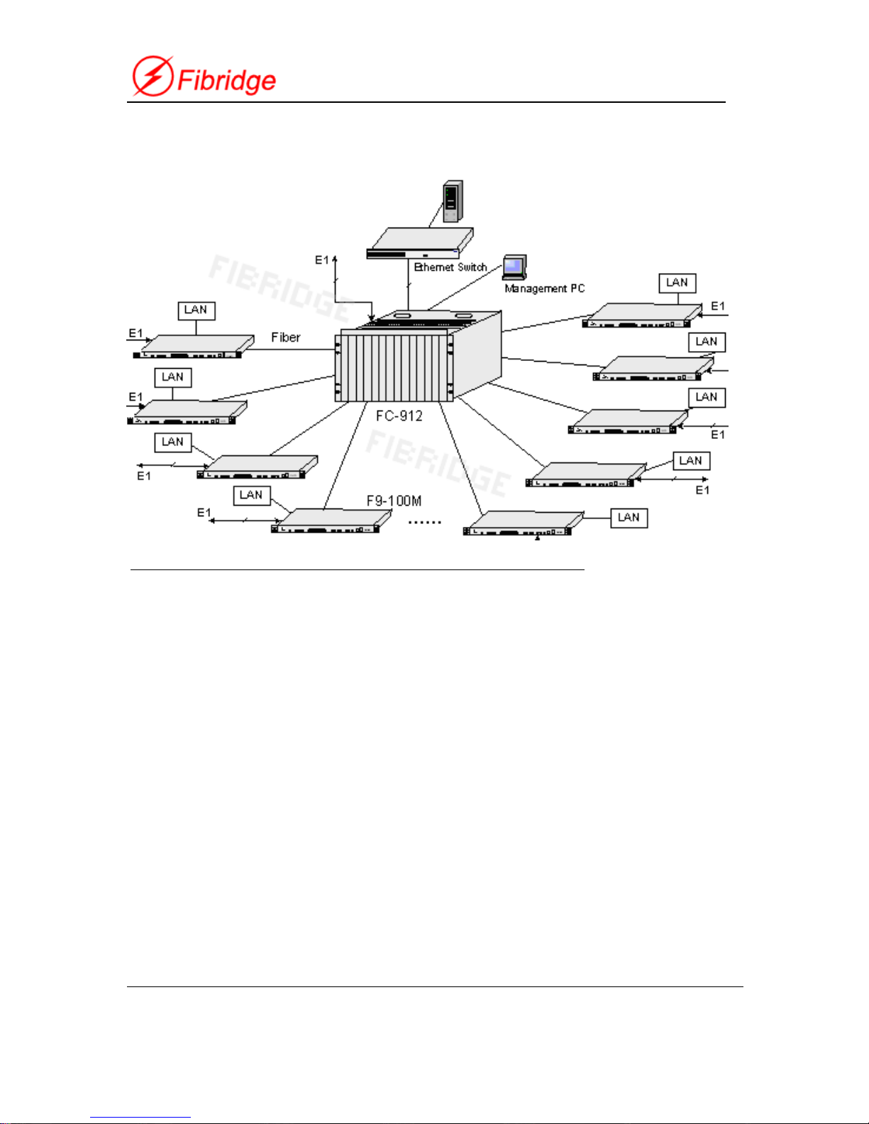
3.2. Star Topology
F9-100M represents standalone of the Multi-service Multiplexer
Figure2 Star Topology
4. Specification
4.1. Optical Port
z Bit rate: 150Mb/s+/-50ppm
z Wavelength: 1310nm/1550nm
z Output power: -11 to -4dBm
z Sensitivity: better than -36dBm
z Connector: FC/SC/ST
z Redundant backup optical port optional
z Auto Laser shutdown (ALS) Optional

4/8/16E1 Multiplexer User Manual V2.1
Beijing Fibridge Co., Ltd.
Tel: +8610-58858988 Fax: +8610-58858520 http://www.fibridge.com
- 7 -
4.2. E1 Port
z Data rate: 2048Kbps
z Code type: HDB3
z Compliant with G.703, G.704
z Impedance:75Ω(Unbalanced), 120ohm(Balanced)optional
z Connector: BNC(75Ω), RJ45(120ohm)
z Jitter: Compliant with ITU-T G.742 and G.823
z Unframed mode
z Numbers: 4/8/16 optional
4.3. Ethernet Port
z Compatible with IEEE802.3, IEEE802.3u
z Speed: 10/100MpbsMbps
z Full/Half duplex auto negotiating
z Connectors: RJ-45
z MDI/MDI-x auto negotiating
z Ethernet port: 2 ports
4.4. Phone Port
z Available for daily telephone communication
z 64Kbps PCM Code
z When picking up the local side, the remote side rings.
z One side hung up, the other side sounds busy.
4.5. Data Port
z RS232/RS485 Protocol

4/8/16E1 Multiplexer User Manual V2.1
Beijing Fibridge Co., Ltd.
Tel: +8610-58858988 Fax: +8610-58858520 http://www.fibridge.com
- 8 -
z For RS232, Bit rate: 4.8Kbps-115.2Kbps
z Connector: DB9, male, check table1 for the definition
Table1 Definition of the Data DB9
PIN
2 3 5 1, 4 6 7 8 9
Protocol
RS232 RS485
Definition
RX TX GND N.A.
TX-
(Z)
TX+
(Y)
RX-
(B)
RX+
(A)
4.6. Management Port
z Type: Console management
z Protocol: RS232, bit rate 9600bps or 19200bps
z Connector: DB9, male, check table2 for the definition
Table2 Definition of the Manag ement DB9
PIN
2 3 5 Others
Definition
RX TX GND N.A.
4.7. Power Supply
z Input voltage:
AC: 100V ~ 240V, 50/60Hz
DC: -48V
z Power Consumption :5W
6789
12345

4/8/16E1 Multiplexer User Manual V2.1
Beijing Fibridge Co., Ltd.
Tel: +8610-58858988 Fax: +8610-58858520 http://www.fibridge.com
- 9 -
4.8. Operating Environment
z Temperature:0℃—50℃
z Humidity:95%,no condensing
4.9. Device Size
z 4/8E1 Standalone device
434mm (W) × 44mm (H) × 200mm (D)
z 16E1 Standalone device
434mm (W) × 44mm (H) × 234mm (D)
z Chassis size
19 inch (W) × 6U (H) × 300mm (D)
5. Device Panel
5.1. 4/8E1 Multi-service Multiplexer, Standalone
5.1.1. Front Panel of 4/8E1 Multi-service Multiplexer
Figure3 Front Panel of the 4/8E1 Multiplexer standalone
LEDs Buttons Phone Power Switch

4/8/16E1 Multiplexer User Manual V2.1
Beijing Fibridge Co., Ltd.
Tel: +8610-58858988 Fax: +8610-58858520 http://www.fibridge.com
- 10 -
5.1.2. Back Panel of 4/8E1 Multi-servic e Multiplexer
Figure4 Back Panel of the 4/8E1 Multiplexer standalone
5.1.3. LEDs Description of 4/8E1 Multi-service Multiplexer
Talbe3:LEDs description of the 4/8E1 Multiplexer standalone
LEDs Color Stat. Description
PWR Green ON Power Supply OK
ARL Red
ON/
Blink
ARL is on When local device has any alarm. ARL
blinks when remote device has alarm but no alarm
at local device.
OPTB Green ON
Optical-B work state indicator.
OPTB is on when Optical-B works.
OPTA Green ON
Optical-A work state indicator.
OPTA is on when Optical-A works.
NOPB Red ON
NOPB is on when no optical signals is detected by
RX of Optical-B Port.
NOPA Red ON
NOPA is on when no optical signals is detected by
RX of Optical-A Port.
Power IN Ethernet
Optical Port
5
th
-8th E1
1
st-4th
E1
Mgt
Data
 Loading...