

Fibersystem 21-219 Technical Manual
Fiberoptic IEEE C37.94 - G.703 E1 mux
21-219
Technical manual
Technical Manual 90_20_0113R0
1

About this manual
About the contents of this manual
The information in this document may be changed at any time without notice.
T able of Contents
About the contents of this manual 2
Table of Contents 2
Version and revision history. 3
Revision history for product: 3
Revision history for this document. 3
Functional 4
IEEE C37.94 4
G.703 E1 2048kbit/s 5
Applications 6
Features 8
Fiberoptic and data transfer protocol 8
G.703 – E1 8
Power Supply. 8
Environmental conditions 8
CE compliance 8
Mechanical 8
EMC compliance 8
Insulation 9
Physical size and Weight 9
Unpacking. 10
Product 21-219 consists of: 10
Serial number. 11
Front Panel. 11
Back Panel. 11
BNC 75 Ohm G.703 E1 Port 12
Fiber Optic IEEE C37.94 Ports. 13
Functional earth/ground, FE. 13
Normal use 14
Config rotary switch 14
External clock 15
Internal clock – “Master mode” 15
Power on. 16
LED-status. 16
CE - mark 18

3
V ersion and revision history .
Revision history for product:
Revision R0.
Product released for serial production. 2006-05-26.
Revision history for this document.
Revision AK0.
2006-05-30, AnNy, document created.
Revision R0.
2006-06-05, AnNy, document released.
Document properties.
Last saved: 6/5/2006 3:42:00 PM
Filename: Technical Manual 90_20_0113R0
Author.
Created by Anders Nyström.
Last saved by Anders Nyström.

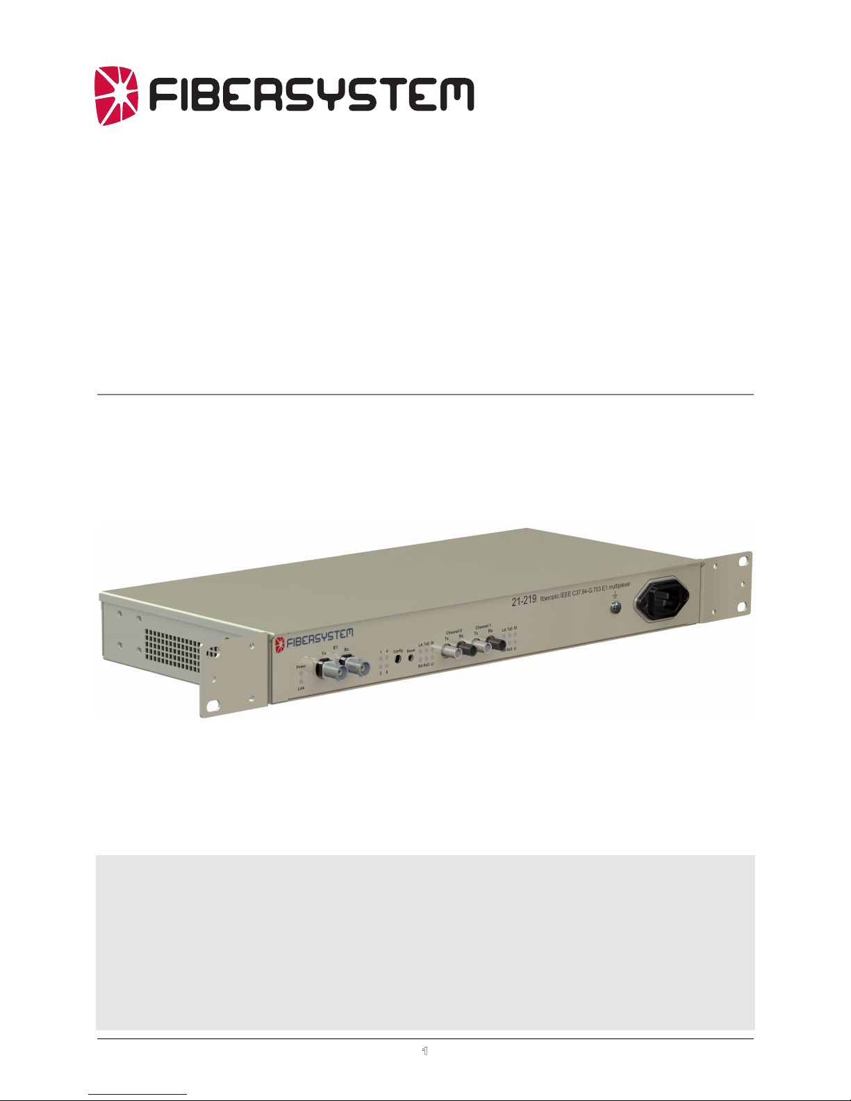
General description
Functional
The 21-219, Fiberoptic IEEE C37.94 - G.703 E1 converter is intended to extend
distance and galvanic isolate the teleprotection equipment for substations connection
to telecom network.
IEEE C37.94
The standard “IEEE C37.94-2002, IEEE Standard for N times 64 Kilobit per
Second Optical Fiber Interfaces between Teleprotection and Multiplexer Equipment”
describes a fiberoptic intra-substation communication links between teleprotection
equipment and multiplexers.
125µs 250µs 375µs 500µs
(256 bit frame)
0hgfedcb 0 0 0 1a 111
( 16 bits )
Header (sync)
1/ss/rr/qq/p 0 1 0 1p 010
( 48 bits )
Overhead
01
……...
D1
( 192 bits )
Channel Data (payload)
……...
/D1 D2 /D2 D3 /D3 D4 /D4 D96 /D96
The bit c in “Header” is used for “Yellow Alarm”. (Every other frame).
Bits p,q,r and s in “Overhead” form a HEX-value indicating the number of timeslots
used for data.
0.0.0.1 for N=1
0.0.1.0 for N=2
….
1.1.0.0 for N=12 , (0CH).
12 timeslots, (1 timeslot has 8bits
Î 12x8bits=96bits. With complement bits Î
2x96=192 bits). Data bits in not used timeslots are set to 1.
4
G.703 E1 2048kbit/s
The G.703, E1, 2048kbit/s unbalanced, (75 Ohm BNC), ports are intended to
connect to, for example, a leased telecom line.
21-219
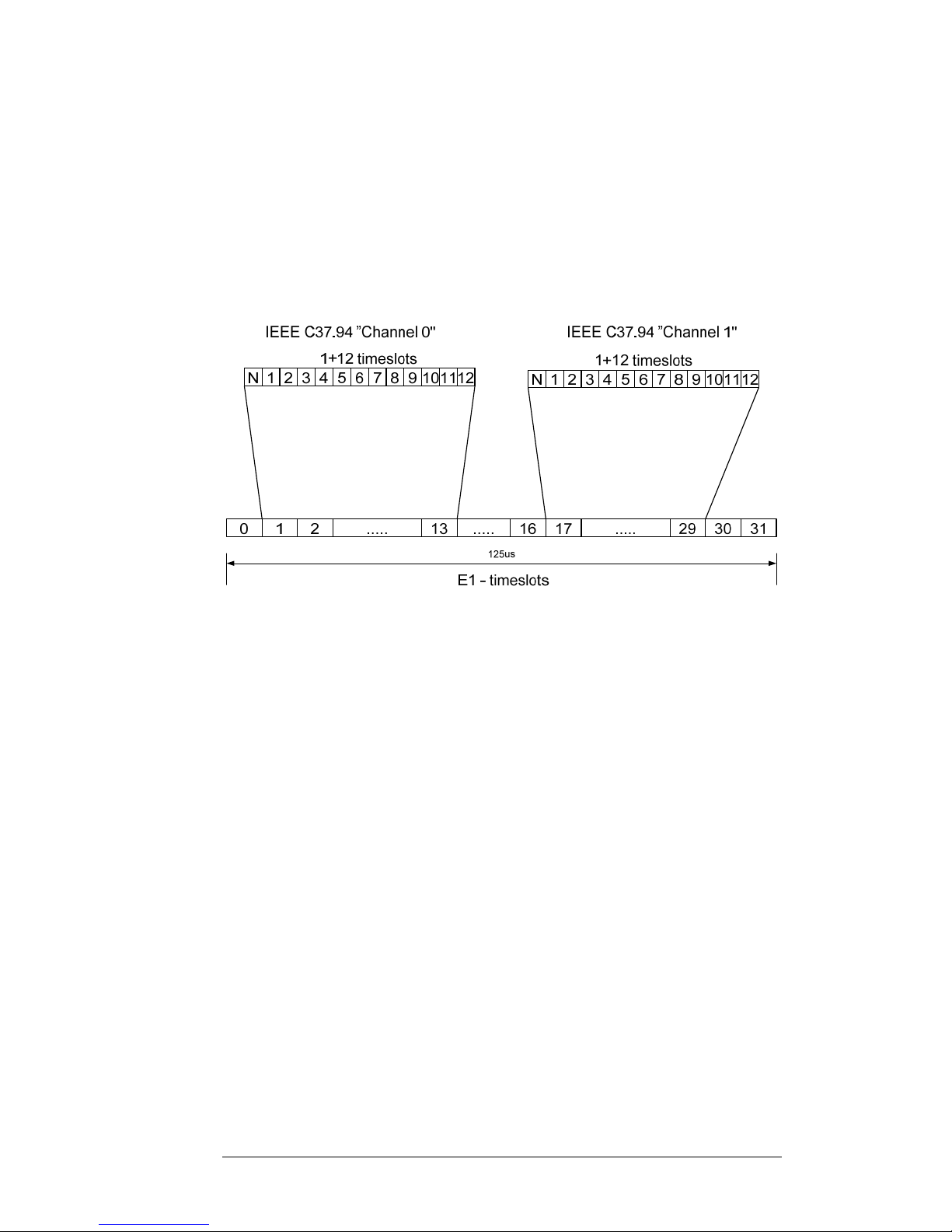
There are two C37.94 fiber optic ports that are multiplexed into one E1-protocol.
“Channel 0” is inserted/extracted in timeslot 1 – 13 in the E1-protocol.
“Channel 1” is inserted/extracted in timeslot 17 – 29 in the E1-protocol.
E1 timeslot 0 contains framing/synchronization information. Timeslots 14, 15, 16, 30
and 31 are ignored at receive and set to 0 at transmit.
In the IEEE C37.94 protocol each data bit is followed by its complement. Only
“true”, (non complement), data bits are transferred to E1-protocol.
The N is fetched from the IEEE C97.94 protocol indicating the number of timeslots
used in the protocol.
The 21-219 transfer the N-value but don’t use it for any other purpose.
All data bits in all 12 timeslots are transferred, regardless of the value of N.
5
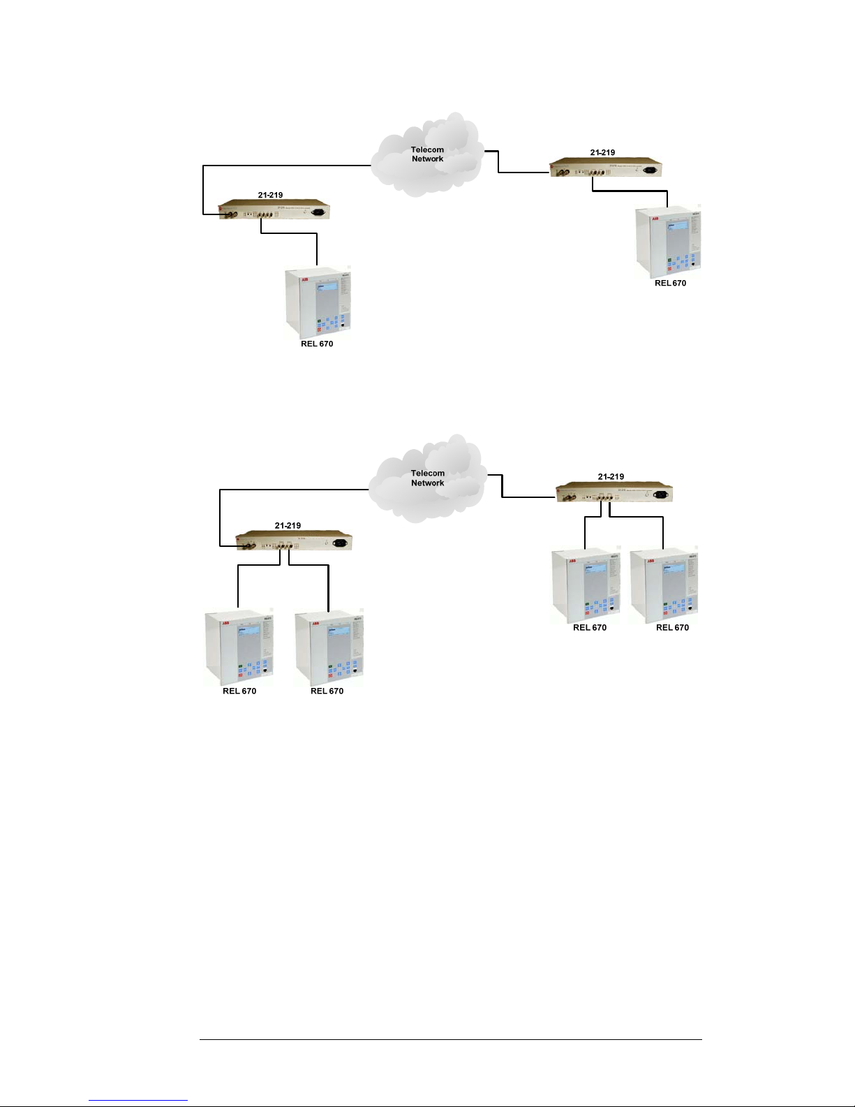
Applications
Singel IEEE C37.94 link via Telecom network.
Dual IEEE C37.94 link via Telecom network.
6
 Loading...