

Fibersystem 21-180 Technical Manual
Fiberoptic G.703 Converter
21-180
Technical manual
FS18134-Technical-Manual-21-180-R2
1

About this manual
About the contents of this manual
The information in this document may be changed at any time without notice.
T able of Contents
About the contents of this manual 2
Table of Contents 2
Version and revision history. 3
Revision history for product: 3
Revision history for this document. 3
Functional 4
Fiber Optic G.703 Codirectional 4
Applications 4
Features 6
Fiberoptic and data transfer protocol 6
G.703 – Codir 6
Power Supply. 6
Environmental conditions 6
CE compliance 6
Mechanical 6
EMC compliance 6
Insulation 7
Physical size and Weight 7
Unpacking. 8
Product 21-180 consists of: 8
Serial number. 9
Front Panel. 9
Back Panel. 9
G.703 Codir Port 11
Fiber Optic Port. 11
Functional earth/ground, FE. 12
Signal ground - Protective earth/ground. 12
Normal use 14
Config rotary switch 14
External clock 15
Fiber clock. 15
Internal clock – “Master mode” 15
Power on. 16
LED-status. 16
CE - mark 18

3
V ersion and revision history .
Revision history for product:
Revision R0.
Product released for serial production. 2006-06-26.
Re
vision history for this document.
Revision AK0.
2006-06-22, AnNy, document created. Revision
R0.
2006-06-26, AnNy, document released.
Revision R1.
2006-06-26, AnNy, applications updated.
Revision R2
2018-03-12, MiLa, document corrected.
Document properties.
Last saved: 12/3/2018 13:05:00
Filename: FS18133 Technical Manual
21-170 R4
Author.
Created by Anders Nyström
.
Last saved by Mikael Larsson
General description
Functional
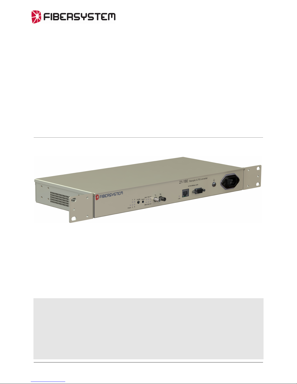
The 21-180, Fiberoptic G.703 converter is intended to extend distance and galvanic
isolate the teleprotection equipment for substations connection to telecom network.
Fiber Optic G.703 Codirectional
The ITU-standard “G.703 64kbit/s codirectional interface” describes a galvanic
interface. This interface is for example commonly used by teleprotection equipment
for connection to telecom multiplexers.
The codirectional interface is transferred at one balanced pair for each direction.
21-180
The 21-180 converts the codirectional interface signals to a proprietary fiber optic
protocol.
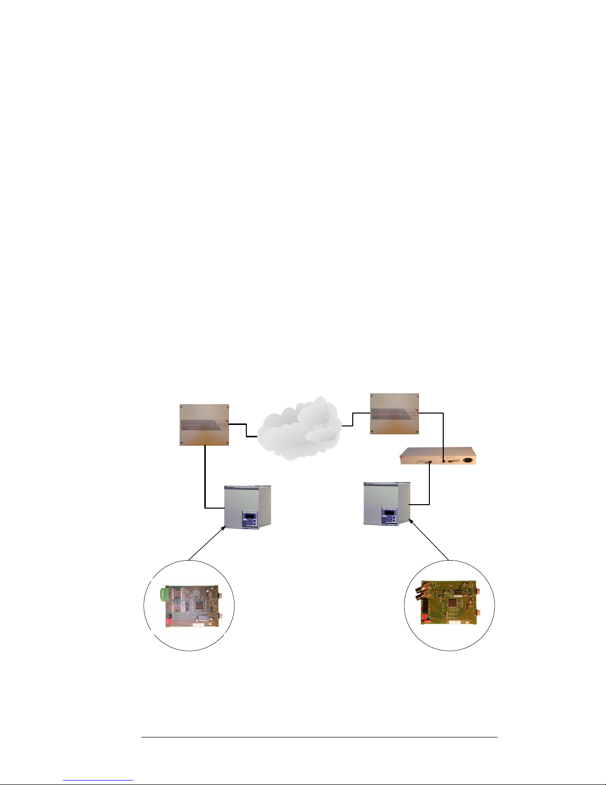
Applications
The fiberoptic port of the ABB REL55x/56x , Line Differential Protection
Terminals, is directly connected to the fiberoptic port of 21-180. The 21-180 Codirport is then connected to a 2048kbps G.703 E1 multiplexer.
64kbps
fiber optic
interface
60-00-2721
Telecom
Network
REL 55x / 56x
REL 55x / 56x
E1 Multiplexer
E1 Multiplexer
21-180
64kbps galvanic interface
60-00-3521
G.703
64kbps codir
fiber optic
G.703
64kbps codir
galvanic
G.703
64kbps codir
galvanic
4
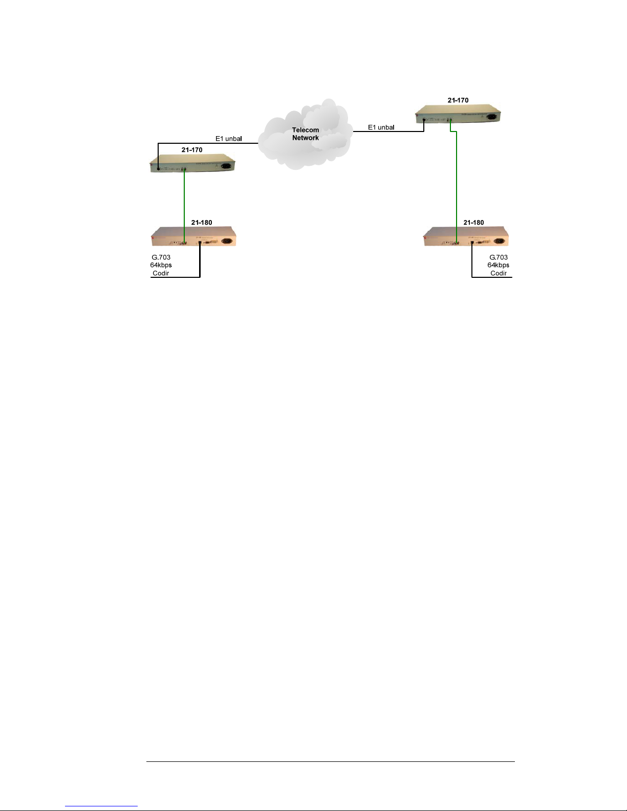
Or connect to another Fibersystem product using the same fiber optic protocol.
5

6
Fea tures
Fiberoptic and data transfer protocol
Data speed/protocol Fibersystem proprietary protocol.
Optical data
Wavelength 820nm
Fiber optical connector ST
Optical System budget 13dB with multimode fiber,
(62.5/125 um)
9dB with multimode fiber,
(50/125 um)
Typical distance 2km (6dB systemmargin for 62.5/125
and 3dB margin for 50/125).
G.703 – Codir
Interface 9-pin female D-sub or RJ45. 120Ohm.
Protocol G.703, 64 kbit/s.
Power Supply.
48V DC to 250V DC, + 20%
110V AC to 230V AC, 50Hz, + 20%.
AC connector IEC 320, 3 pin.
Power consumption <20W.
Environmental conditions
Operating temperature range -25 to +70 °C.
Storage temperature range -40 to +85 °C.
Relative humidity operating 5 to 95%.
Relative humidity storage 5 to 95% non condensing.
CE compliance
Immunity EN 61000-6-2
Emission EN 61000-6-4
LVD EN 50178, RIV = 250V OVC = III
Mechanical
Vibration IEC 60255-21-1 Class 2
Shock IEC 60255-21-2 Class 2
Sesmic IEC 60255-21-3 Class 2
EMC compliance
ESD IEC 60255-22-2 Class 3, contact 6kV, air 8kV.
Radiated IEC 60255-22-3 / IEEE/ANSI C37.90.2; 35V/m
Burst Power IEC 60255-22-1 Class III
Burst Communication IEC 60255-22-1 Class II; 0,5kV diff, 1kV common mode
Fast transient Power IEC 60255-22-4 Class IV
Fast transient Communication IEC 60255-22-4 Class II; 1kV
 Loading...