

Page 1
1
Technical Manual 90-20-0107R4
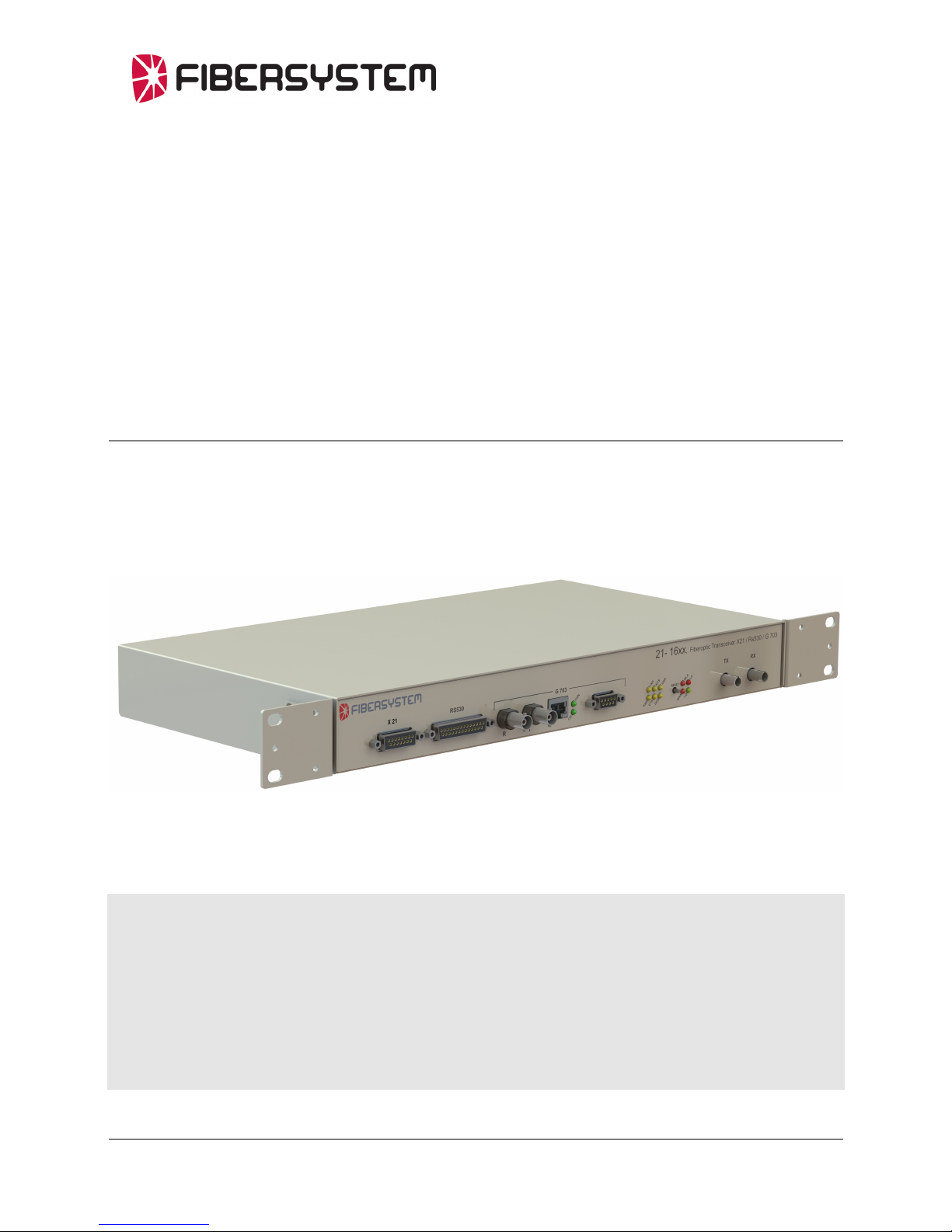
Fiberoptic G.703 / X.21 (/ RS530) modem
21-1601 / 21-1651 / “21-16xx”
Technical manual
Page 2

2
About this manual
About the contents of this manual
The information in this document may be changed at any time without notice.
T able of Contents
About the contents of this manual 2
Table of Contents 2
Version and revision history. 3
Revision history for product: 3
Revision history for this document. 3
Functional 4
History 4
Present products 4
Power supply. 5
Fiber Optic G.703 Codirectional 5
Fiber Optic G.703 Contradirectional 5
G.703 2048kbit/s unbalanced 5
X.21 5
RS530 / RS530A 5
Fiber optic protocol 6
Applications 6
Features 7
Fiberoptic and data transfer protocol 7
G.703 – 2048kbit/s unbalanced 7
G.703 – balanced, codirectional 7
G.703 – balanced, contradirectional 7
X.21 7
RS530 7
Power Supply. 8
Physical size 8
Environmental conditions 8
Unpacking. 9
Product 21-1601 consists of: 9
Product 21-1651 consists of: 9
Serial number. 11
Front Panel. 11
Back Panel. 11
Mounting 11
Power - DC 11
X.21 12
RS530 Port 13
G.703 2048kbps, E1 Port - BNC 75 Ohm 14
G.703 Codir/contra Port. 15
Fiber Optic Port. 16
Factory settings 17
Configuration – remove top lid. 17
Configuration 20
Type of interface 20
G.703 E1 2048kbps. 21
Codir – Contra, CO/CON 21
Select clock mode for Contra 21
Clock source. 22
Internal clock – “Master mode” 22
Clock speed/data rate. 23
X.21 mode. 24
RS530 mode. 25
Ground selection. 25
Super Reset. 25
Power on. 26
LED-status. 26
CE - mark 28
Page 3

3
V ersion and revision history .
Revision history for product:
Revision Rx.
Product released for serial production. 199x-xx-xx.
Revision Rx+.
New power supply manage both DC and AC. 2001-02-27.
From serial number 4258 - .
Revision Rx++.
Port RS530 removed October 2006.
From serial number 13758 - .
Revision history for this document.
Revision x.
199x-xx-xx, RoPa, document created.
Revision R2.2.
2003-xx-xx, AnNy, new logotype.
Revision R3.
2005-06-19, AnNy, new document layout and contents updated. New
logotype.
Revision R4.
2
018-05-21, MiLa, document updated with new pictures and logo.
Document properties.
Last saved: 21/5/2018 15:52:00
Filename: Technical Manual 90-20-0107R4
Author.
Created by Anders Nyström.
Last saved by Mikael Larsson.
Page 4
4
General description
Functional
The modem 21-1601 and 21-1651 from Fibersystem are combined fiberoptic
synchronous and asynchronous modem with four different interfaces.
The interfaces are:
G.703 unbalanced 2Mbps,
G.703 balanced Nx64Kbps,
X.21
RS-530, not mounted on products produced after October 2006.
The modems are available in 2 versions.
21-1601 runs on 110-230 VAC , +/- 20%, power supply.
21-1651 runs on 48-250 VDC, +/- 20%, power supply.
The modem can be mounted in 19 rack with the mounting brackets included with the
product.
In synchronous mode the data rate are settable from 4.8kbps to 2048kbps.
To run the modem in asynchronous mode the data rate must be set to at least 8 times
the actual data rate giving a maximum asynchronous rate of 256kbps.
The modem can be configured to use three models of clock generation:
Internal clock, where the modem generates the transmit clock.
External clock, where the modem recovers the clock from the selected
interface.
Loop clock, where the modem recovers the clock from the fiber link.
The 21-1601 or 21-1651 can be connected to a telecom network or “back-to-back”.
The front panel is marked 21-16xx and the product is often referred to as “21-16xx”.
History
The 21-16xx has been delivered in 4 versions:
Product number Version
21-1601 ST multimode version with 100 –240 Volt AC/DC power supply
21-1651 ST multimode version with 48VDC power supply
21-1605 ST singlemode version with 100 –240 Volt AC/DC power supply
21-1655 ST singlemode version with 48VDC power supply
Present products
21-1601 Fo modem G703/X.21 (/RS530) 230V
21-1651 Fo modem G.703/X.21 (/RS530)
This manual will describe these products.
For singlemode application we recommend to use Fibersystem´s multimode to
singlemode converters, for example 21-203, “Fo MM/SM 4B/5B konv SC-SC
80km“.
Page 5

5
Power supp
ly.
Both 21-1601 and 21-1651 are equipped with the same type of power supply.
The power supply accepts a wide range of voltages.
48-250VDC, +/- 20%.
110-230VAC, +/- 20%.
The only thing that differs between 21-1601 and 21-1651 is the type of connector for
main power supply.
21-1601 has a IEC 320, 3-pin power connector. It also have a mains filter and a fuse
available for replacement.
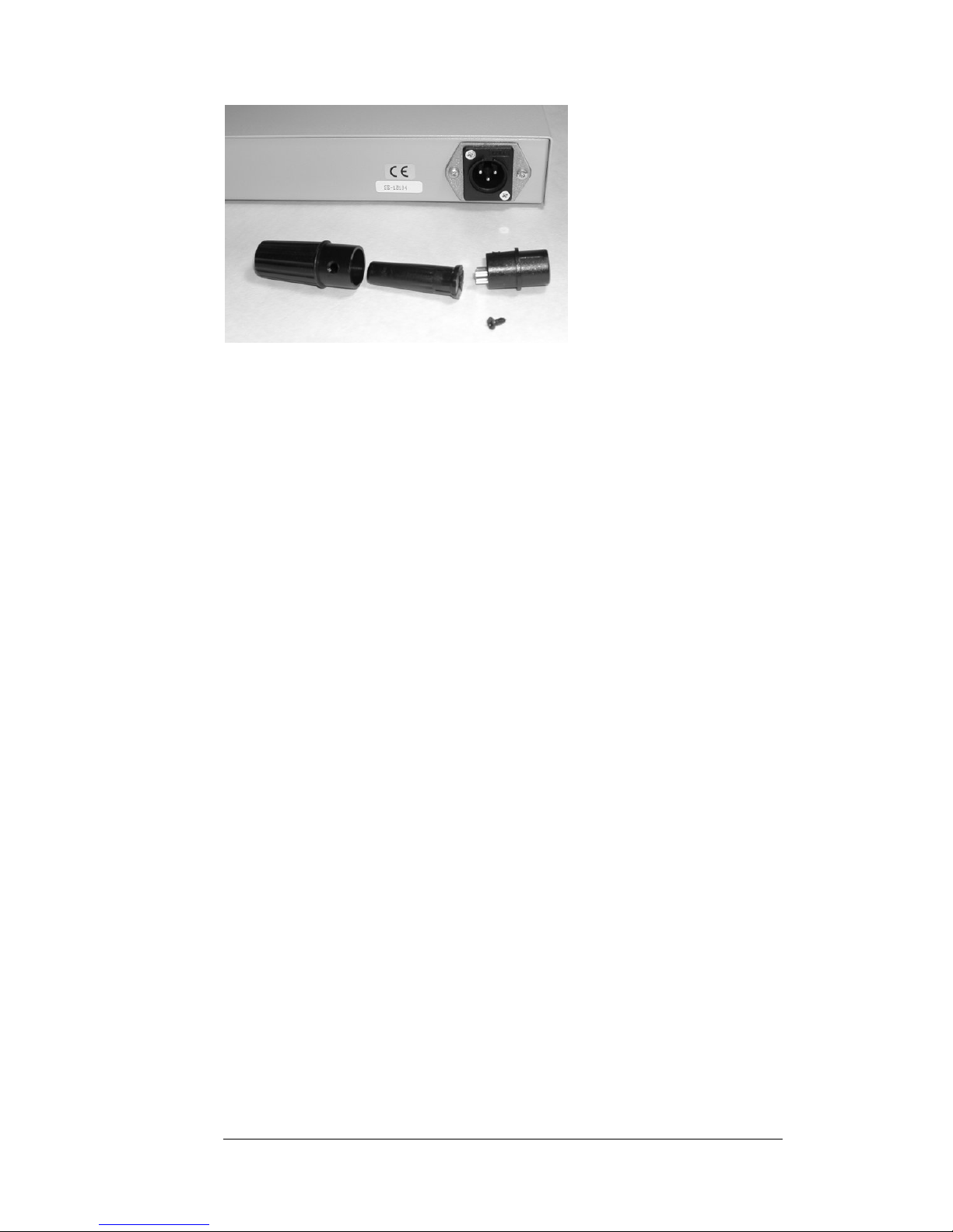
21-1651 has a 3-pin XLR connector. No filter. Fuse not replaceable.
In addition both 21-1601 and 21-1651 can be powered with 48V to 250V.
Fiber Optic G.703 Codirectional
The ITU-standard “G.703 64kbit/s codirectional interface” describes a galvanic
interface. This interface is for example commonly used by teleprotection equipment
for connection to telecom multiplexers.
The codirectional interface is transferred at one balanced pair for each direction.
The 21-16xx converts the codirectional interface signals to a proprietary fiber optic
protocol.
Fiber Optic G.703 Contradirectional
The ITU-standard “G.703 64kbit/s contradirectional interface” describes a galvanic
interface.
The contradirectional interface is transferred at two symmetrical pairs for each
direction. One pair carrying the data signal and the other carrying a composite timing
signal (64kHz and 8kHz).
The 21-16xx converts the contradirectional interface signals to a proprietary fiber
optic protocol.
G.703 2048kbit/s unbalanced
The ITU-standard G.703, E1, 2048kbit/s unbalanced, (75 Ohm BNC), ports are
intended to connect to, for example a telecom multiplexer. The 21-16xx transfer
HDB3-koded signals with or without frameing.
The 21-16xx converts the G.703 2048kbit/s unbalanced interface signals to a
proprietary fiber optic protocol.
X.21
The ITU-standard X.21 is an interface primarily used in telecom for connection of
“customers (DTE) equipment” to “carrier’s (DCE) equipment”.
All signals are balanced.
The 21-16xx converts the X.21 interface signals to a proprietary fiber optic protocol.
RS530 /
RS530A
Only available at products produced before October 2006.
The RS530 interface is a generic connector specification. The connector can be used
for to support RS422, RS423, V.35 and X.21, depending on the implementation.
Specifications for Fibersystems implementation of the RS530 are given later in this
document.
The 21-16xx converts the RS530 interface signals to a proprietary fiber optic protocol.
Page 6
6
Fiber optic protocol
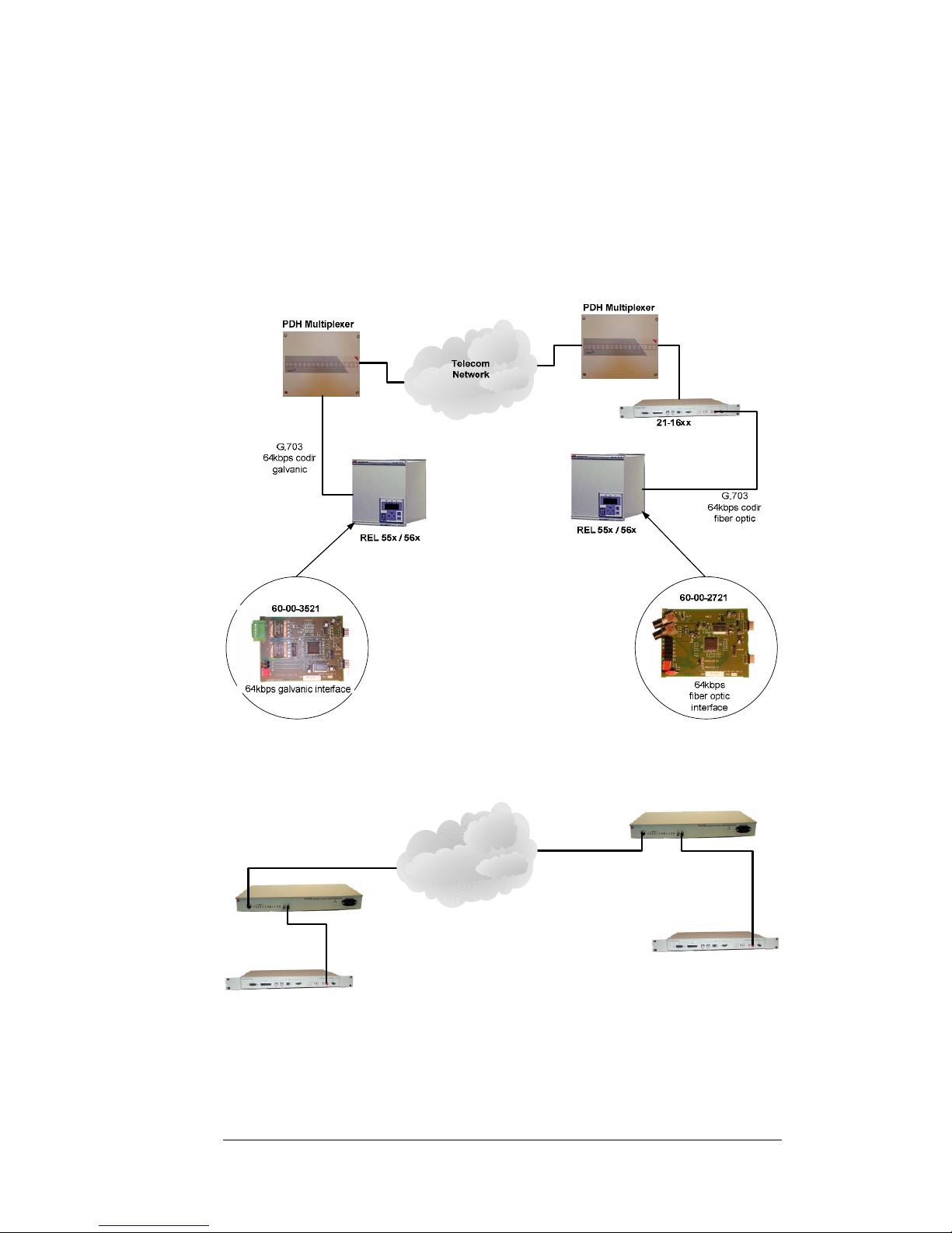
Fibersystems proprietary protocol is used in a number of our products, enabling
interface conversions. For example, configure one 21-16xx for G.703 codir interface
and configure the other 21-16xx , (remote unit), in the link to X.21.
Applications
The fiberoptic port of the ABB REL55x/56x , Line Differential Protection
Terminals, is directly connected to the fiberoptic port of 21-16xx. The 21-16xx Codirport is then connected to a PDH multiplexer.
Or connect to another Fibersystem product using the same fiber optic protocol.
21-16xx
21-16xx
21-170
21-170
Telecom
Network
Page 7

7
Fea tures
Fiberoptic and data transfer protocol
Between differential relay and 21-16xx.
Data speed/protocol Fibersystem proprietary protocol.
Optical data
Wavelength 820nm
Fiber optical connector ST
Optical System budget 13dB with multimode fiber,
(62.5/125 um)
9dB with multimode fiber,
(50/125 um)
Typical distance 2km (6dB systemmargin for 62.5/125
and 3dB margin for 50/125).
G.703 – 2048kbit/s unbalanced
Interface 2 BNCs, unbalanced 75 Ohm.
Protocol HDB3, 2048 kbit/s.
G.703 – balanced, codirectional
Interface 9-pin female D-sub or RJ45.
Protocol G.703 codir, 64, 128, 192 or 256 kbit/s.
G.703 – balanced, contradirectional
Interface 9-pin female D-sub or RJ45.
Protocol G.703 contradir, 64, 128, 192, 256, 384
or 512 kbit/s.
X.21
Interface 15-pin female D-sub.
Protocol RS-422 compatible signal levels, 4.8, 9.6,
19.2, 38.4, 64, 128, 192, 256, 384, 512,
768, 1024, 1536, 2048 kbit/s.
In asynchronous mode up to 256
kbps/s.
RS530
Only available at products produced before October 2006.
Interface 25-pin female D-sub.
Protocol RS-422 compatible signal levels,
(pin 5 and 6 – RS423).
4.8, 9.6, 19.2, 38.4, 64, 128, 192, 256,
384, 512, 768, 1024, 1536, 2048 kbit/s.
In asynchronous mode up to 256
kbps/s.
Page 8

8
Power Supply.
48V DC to 250V DC, + 20%
110V AC to 230V AC, 50Hz, + 20%.
AC connector IEC 320, 3 pin.
Power consumption <20W.
Physical size
The unit can be mounted in a 19” rack.
By adjusting, the rack mount brackets, the unit can also be mounted on a wall or
similar.
Height 44 mm
Width 483 mm (380 mm without rack mount brackets).
Depth 238 mm (from front to back, connectors excluded).
Weight 3 kg
Environmental conditions
Operating temperature 0 - 50 oC
Page 9
9
Unpacking.
Check that the packing material has no damage. If damages are discovered on packing
material, contact your shipping company, before unpacking.
The delivered product consists of several parts. Check that all parts are present
according to the list below, and have no damage.
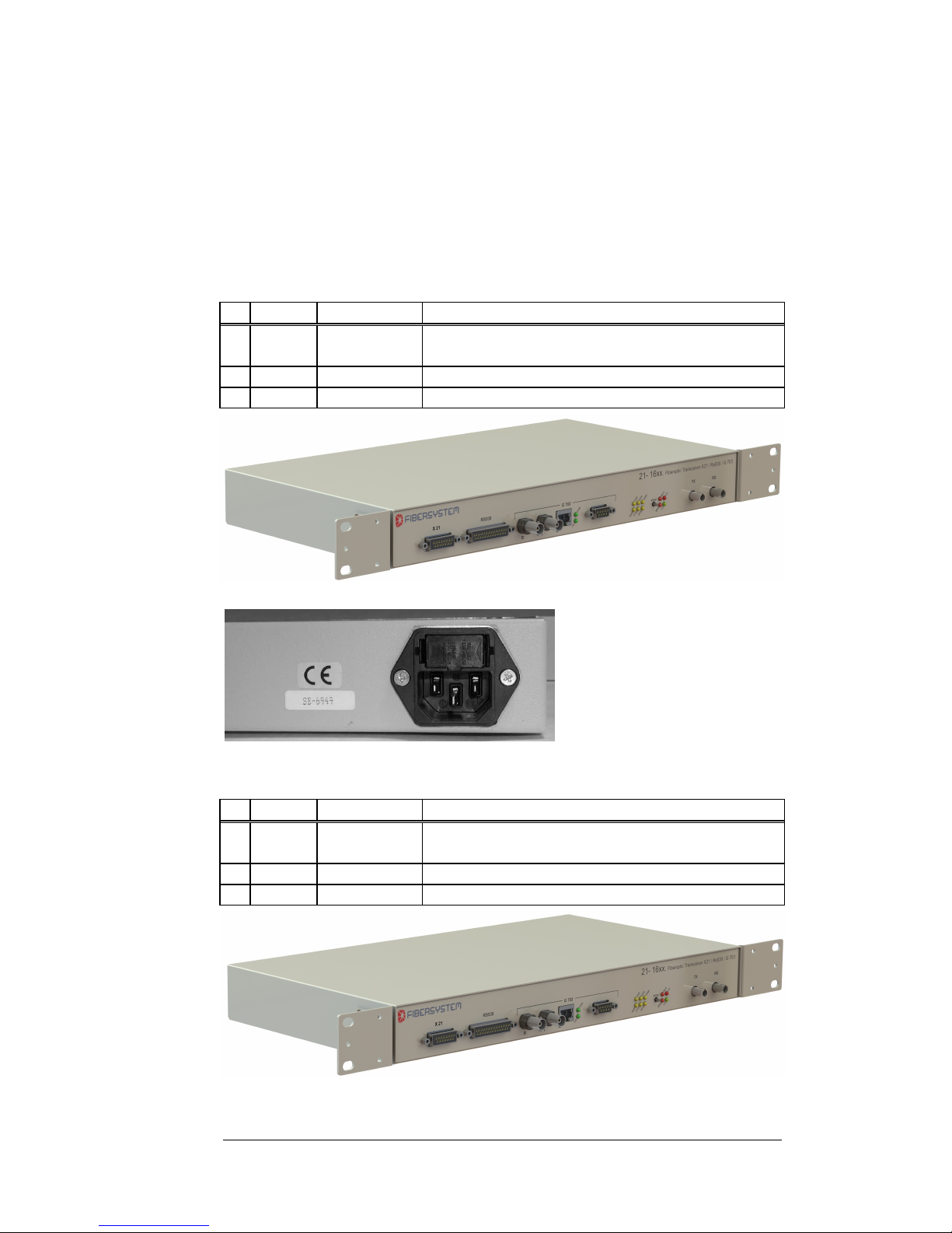
Product 21-1601 consists of:
Quantity Part number Description
1 1 21-1601 Fo modem G703/X.21/RS530 230V
(Part number includes all parts in this list).
2 1 50-65-0106 Power cord, 1.8m European connector.
3 1 90-20-0 This manual
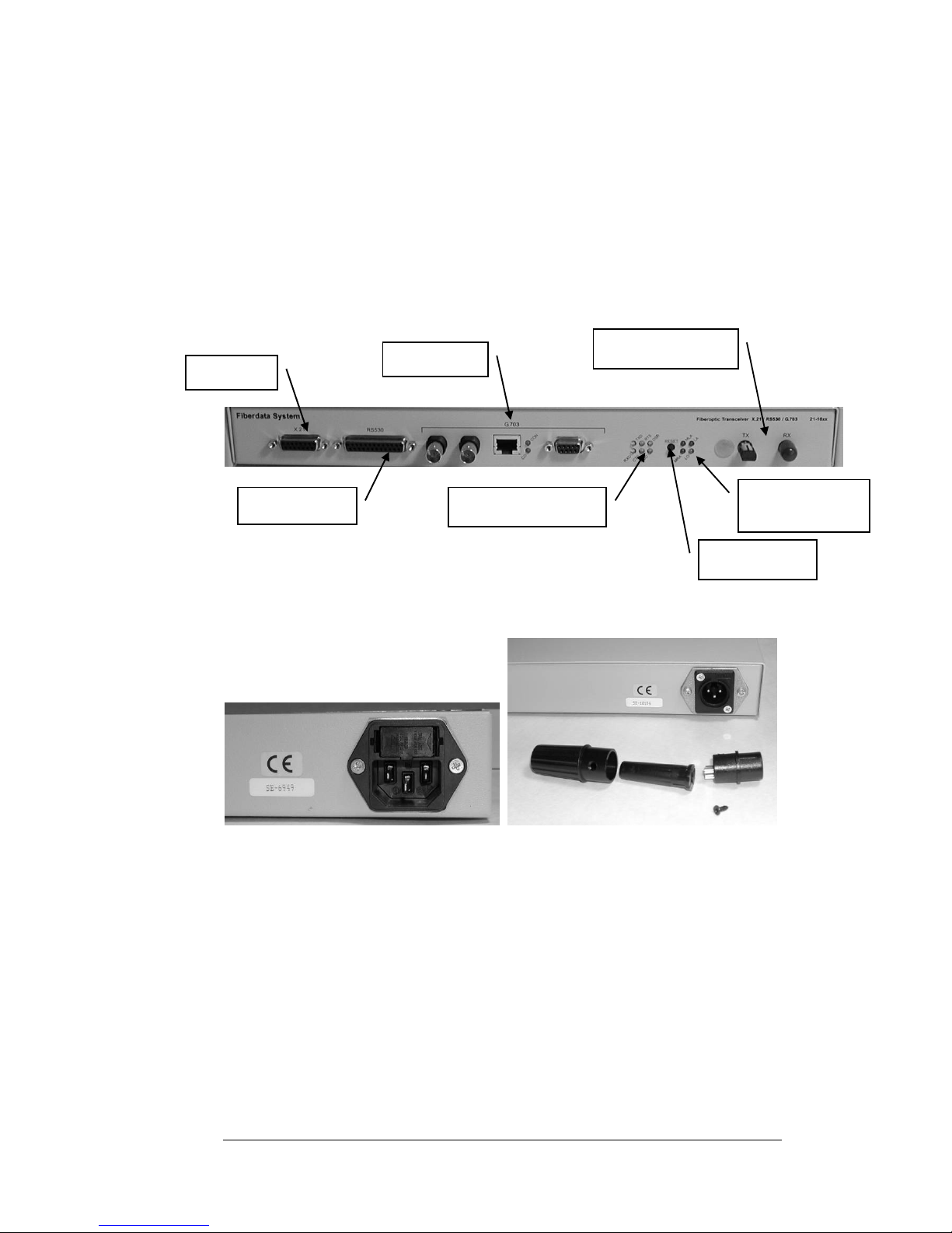
Front on both 21-1601 and 21-1651.
Back 21-1601.
Product 21-1651 consists of:
Quantity Part number Description
1 1 21-1651 Fo modem G.703/X.21/RS530
(Part number includes all parts in this list).
2 1 50-55-0191 Connector 3-pin XLR for cable.
3 1 90-20-0 This manual
Front on both 21-1601 and 21-1651.
Page 10
10
Back and power connector for 21-1651.
Page 11
11
Installation.
Serial number.
The products serial number is the best way for Fibersystem to identify the product.
If the serial number is not noted on your delivery notes, please add the serial number
to your own product documentation. This will be useful at future contact with
Fibersystem.
Front Panel.
*RS530 port is only available at products produced before October 2006.
Back Panel
.
Power connector on 21-1601 Power connector on 21-1651
Moun
ting
The products can be used stand alone or rack mounted.
Power - DC
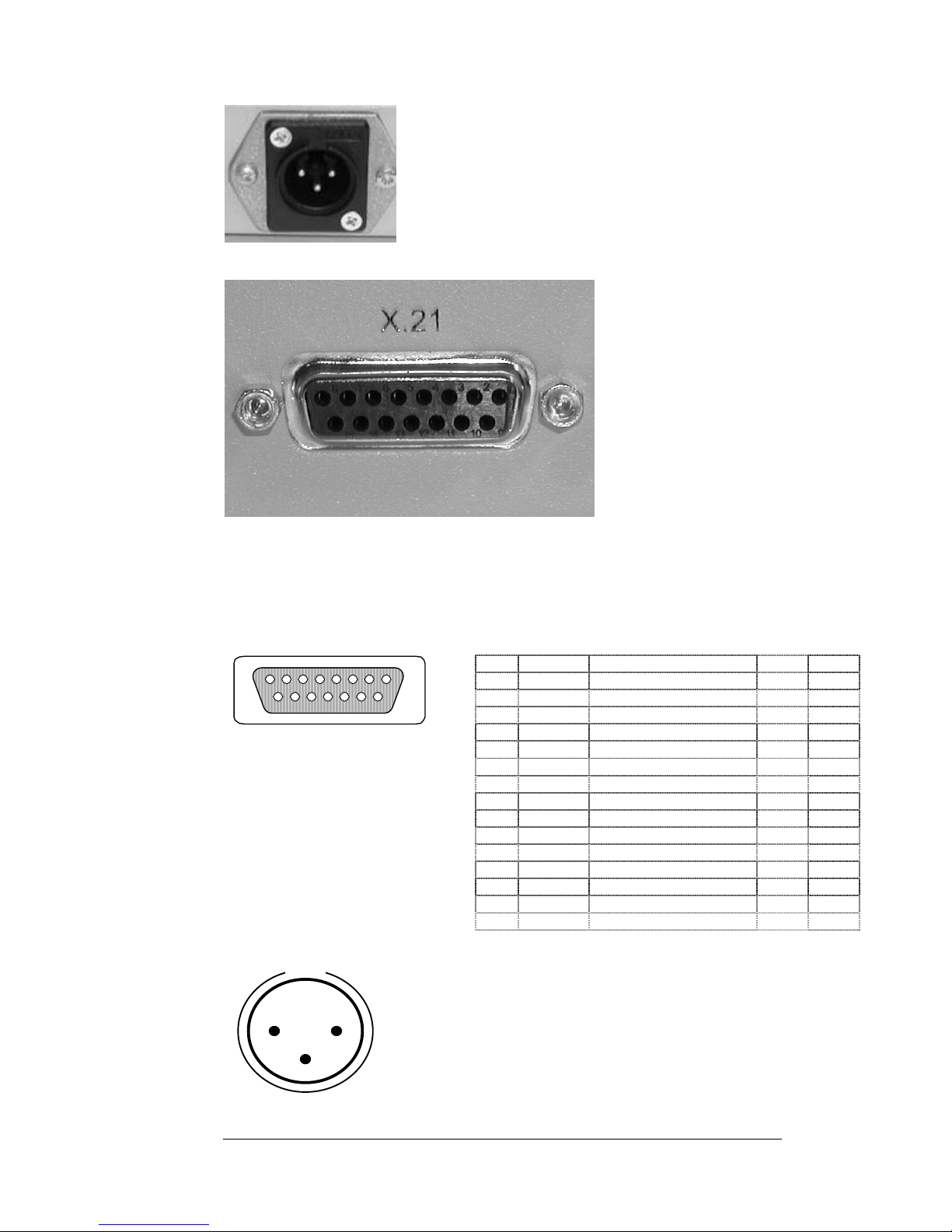
DC power is feed via a XLR connector.
RS530 port *
Fiber Optic Ports
Status LEDs Data
Status LEDs
Fiber optic port
G.703 ports
Reset butto
n
X.21 port
Page 12
12
X.21
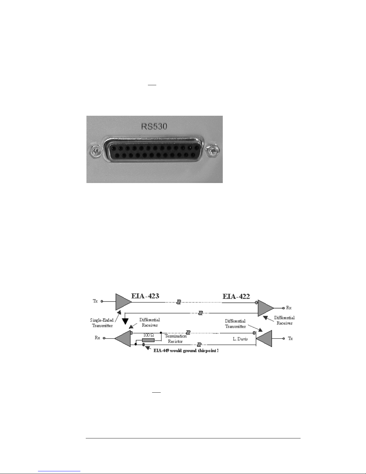
Contact D15 female, (15-pin D-sub).
The X.21 interface is defined as a digital signaling interface between customers (DTE)
equipment and carrier’s equipment (DCE). And is primarily used for telecom
equipment.
All signals are balanced (RS422). There is always a pair (+/-) for each signal.
15
9
8
1
Pin Signal Function DTE DCE
1 Shield Shield – Chassies ground - 2 TxD A Transmit (A) Out In
3 Control (A) Out In
4 RxD A Receive (A) In Out
5 Indication (A) In Out
6 Signal Timing (A) In Out
7 - Unassigned - 8 SGND Signal Ground - 9 TxD B Transmit (B) Out In
10 Control (B) Out In
11 RxD B Receive (B) In Out
12 Indication (B) In Out
13 Signal Timing (B) In Out
14 - Unassigned - 15 - Unassigned - -
1 2
3
Chassi side
1 = 48 – 350V
2 = 0 V
3 = Shield
Page 13
13
The 21-16xx can be configured for DCE or DTE operation by internal straps. See
chapter “Configuration”.
Note 21-16xx shall be seen logically more as an extension cable than as a modem.
Both data and control signals are mirrored to the remote side 21-16xx. Control signals
of the X.21 interface are not used for control of the 21-16xx traffic.
Both data and control signals are clocked in and out of the 21-16xx with the chosen
clock source. See chapter “Configuration”.
RS530 Port
Only available at products produced before October 2006.
RS530 is a standard for a connector more than an interface standard.
The connector pinning can be used to support RS422, RS423, V.35 and X.21 and
more.
Fibersystems RS530 implementation is a differential/balanced communications
interface with some single-ended/unbalanced signals normally used by modem
control signals, CTS and DSR.
Balanced signals use RS422 signaling levels.
Unbalanced signals, CTS pin 5 and DSR pin 6, use RS423 signal levels.
Both CTS and DSR are outputs from 21-16xx. A RS423-output can be connected to
a RS422-input by simply connecting the other input to signal ground.
Note 21-16xx shall be seen logically more as an extension cable than as a modem.
Both data and control signals are mirrored to the remote side 21-16xx. Control signals
of the RS530 interface are not used for control of the 21-16xx traffic.
Both data and control signals are clocked in and out of the 21-16xx with the selected
clock source. See chapter “Configuration”.
Page 14
14
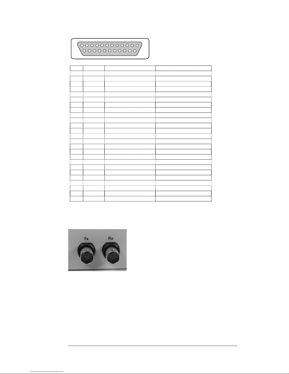
Contact D25 female, (25-pin D-sub).
25
14
13
1
“Out “ sends data out from 21-16xx, “In” receives data.
G.703 2048
kbps, E1 Port - BNC 75 Ohm
The connectors are BNC. Tx-port sends data out from 21-16xx, Rx-port receives
data.
The BNC-connectors are isolated from chassis and both TIP and RING are isolated
from any ground with an input and output transformer.
This gives the opportunity to set up any grounding philosophy.
Best is to use double shielded coax cables as RG81.
In practice grounding the shield to chassis/protective earth/ground, (PE), has given
the best performance, but proper grounding philosophy varies from installation to
installation.
Pin Signal Function Signal direction on D-sub
1 Shield Shield – Chassies ground 2 TxD A Transmit Data (A) In
3 RxD A Receive Data (A) Out
4 RTS (A) Request To Send (A) In
5 CTS Clear To Send Out
6 DSR (A) Data Set Ready (A) Out
7 SGND Signal Ground 8 DCD (A) Data Carrier Detect (A) Out
9 RxC (B) Receive Clock (B) Out
10 DCD (B) Data Carrier Detect (B) Out
11 TxCE (B) Transmitt Clock (B) Out
12 TxC (B) Transmit Clock (B) Out
13
14 TxD B Transmit (B) In
15 TxC (A) Transmit Clock (A) Out
16 RxD B Receive (B) Out
17 RxC (A) Receive Clock (A) Out
18 - - 19 RTS (B) Ready To Send (B) In
20 DTR (A) Data Terminal Ready (A) In
21 - - 22 - - 23 DTR (B) Data Terminal Ready (B) In
24 TxCE (B) Transmitt Clock (A) In
25
Page 15
15
G.703 Codir/contra Port.
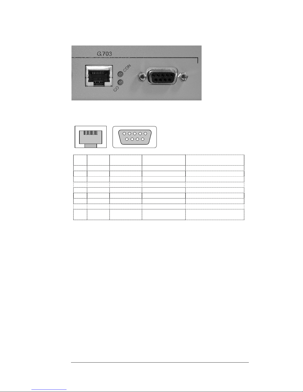
The RJ45 connector and the 9-pin D-sub connector are connected in parallel.
Codir and contra are selectable by strapping pins. See chapter “Configuration”.
LEDs CO and Con shows the selected mode. CO Î Codir. CON Î Contra.
81
9
6
5
1
Clock is only used in Contra mode. The direction of clock signals are selectable by
straps. See chapter “Configuration”.
Always use cables with a good shield. For example S/FTP.
Pin
RJ45
Pin
9-p D-sub
Signal Function Signal direction
1 1 Tx A Transmit data A Out
2 2 Tx B Transmit data B Out
3 3 Rx A Receive data A
4 4 Rx B Receive data A
5 5 TxCA/RxCA Clock Selectable by straps
6 6 TxCB/RxCB Clock Selectable by straps
7 7 TxCA/RxCA Clock Selectable by straps
8 8 TxCB/RxCB Clock Selectable by straps
Shield 9+Shield Shield Shield - (Internally connected to
chassies ground).
Page 16

16
Fiber Optic Port.
The fiber optic connector is of ST type.
Confirm that the attenuation of the fiber optic cable, including splices and patch
cables, doesn’t exceed the system budget. Don’t forget to add a safety margin.
Minimum safety margin is 3dB.
Make sure that the local fiber optic transmitter, marked Tx, is connected to the
remote units fiber optic receiver, marked Rx. And local Rx shall be connected to
remote Tx.
Page 17
17
Configuration
Factory settings
The most common configuration is set at delivery.
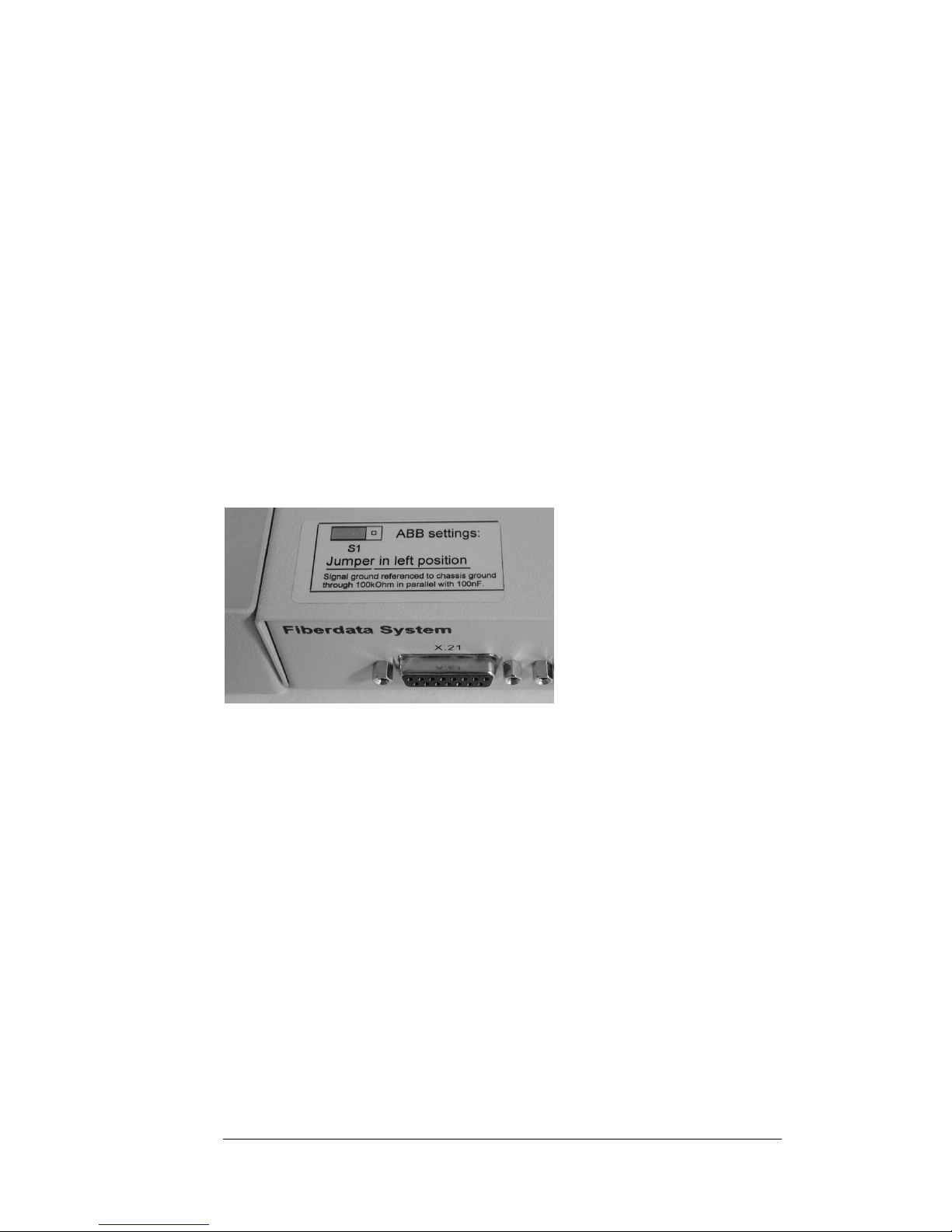
S1 – Signal ground and Chassie ground are connected. Chassie is
connected to Protective Earth(PE)/Ground with the Power
supply cord.
S5 – Codir/Contra
S6 – Codir
S11 – 64kbps , (Position 9).
S2, S3, S4, 15, S16 – DTE, (Only X.21).
S13 – No synchronization of received fiber clock.
S14 – External clock, (Received from electrical interface).
S14 – Phase not used, (No strap).
S6 – Codir
S7, S8, S9 - Contra clock Î Receive clock.
When two 21-16xx are connected back-to-back, one of the 21-16xx should be set to
“Master mode”.
Configuration – remove top lid.
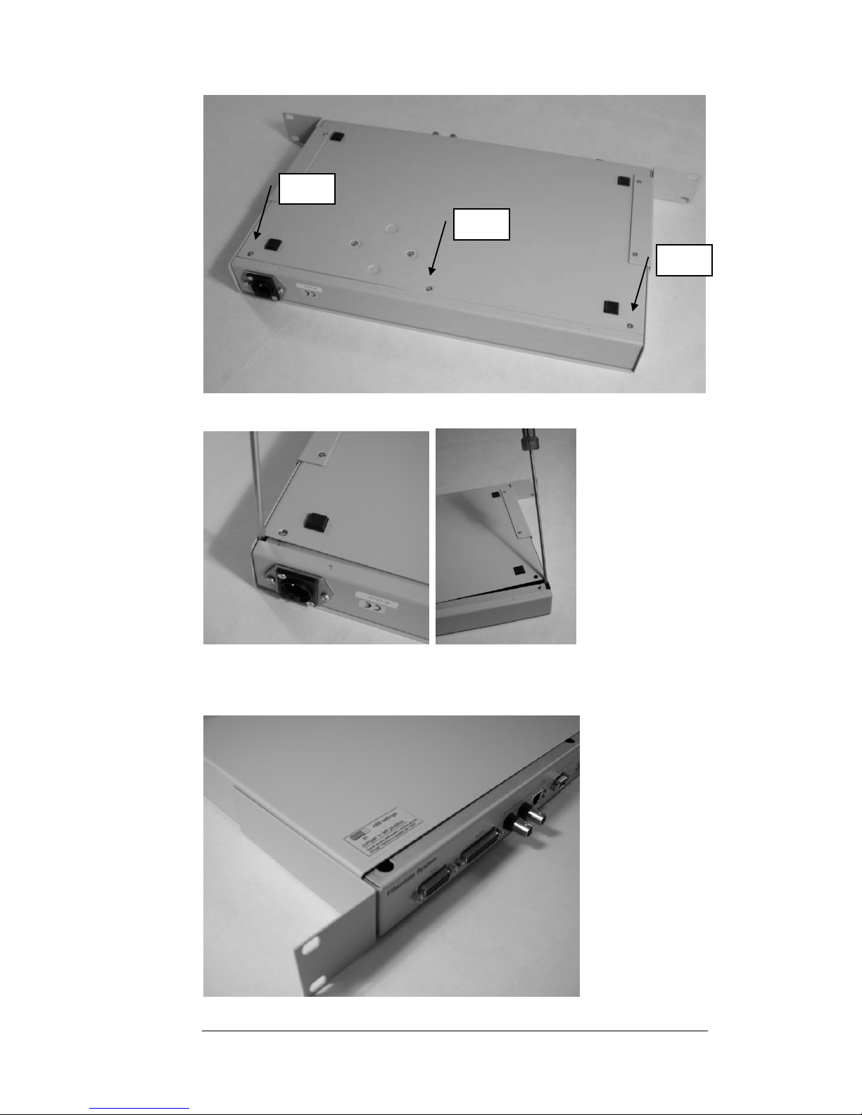
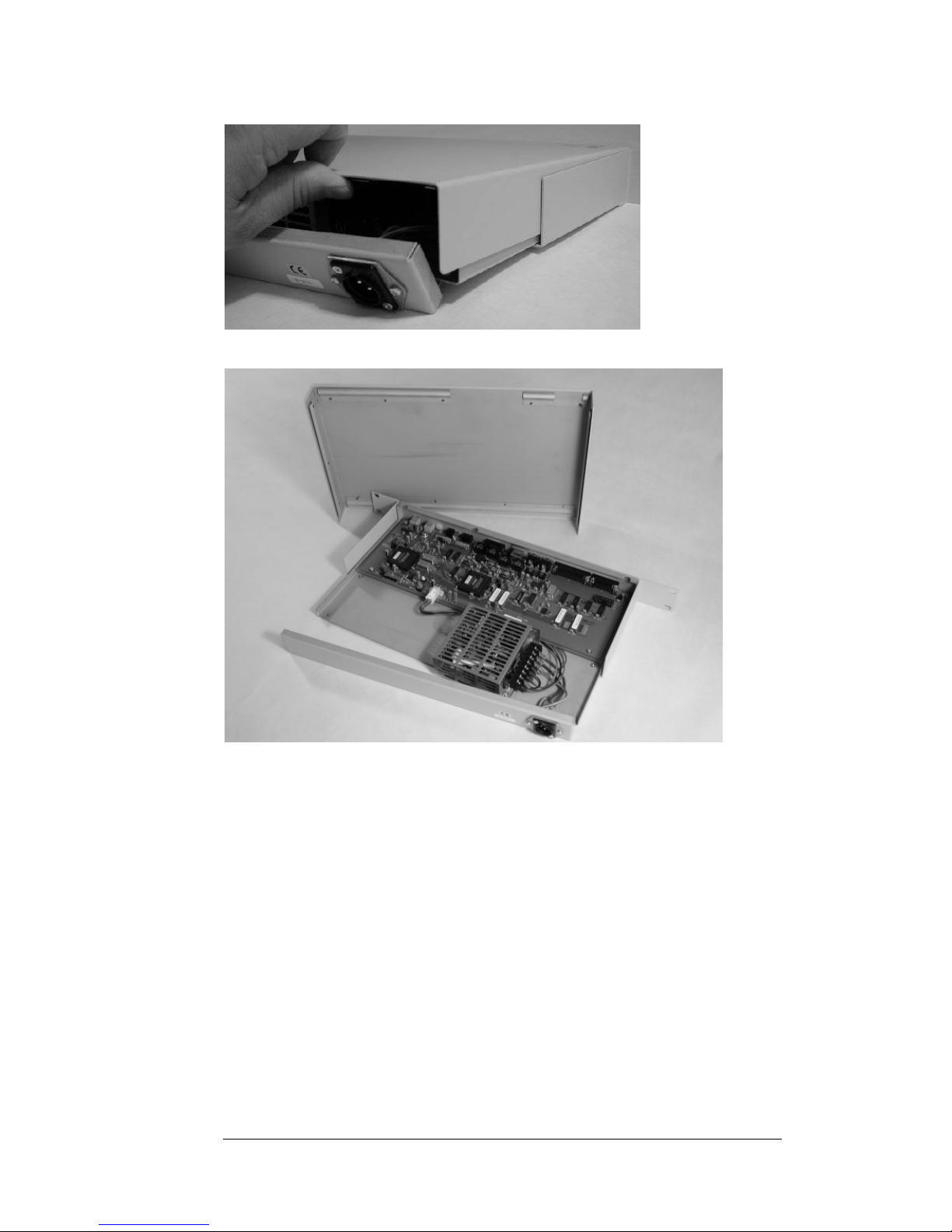
For configuration the 21-16xx must be open by removing the top lid.
Remove power supply cord and turn the unit up-side down.
Page 18
18
Remove 3 screws.
Gently bend with a screwdriver to push out and remove the backpanel.
Don’t remove the cables attached to the backpanel.
Turn the unit so top lid is facing up.
Press/slide the top lid backwards so it loosens from the frontpanel.
Screw
Screw
Screw
Page 19
19
Lift the top lid in back. And remove the top lid.
Now the 21-16xx is ready for configuration.
Disassembled 21-16xx.
Page 20
20
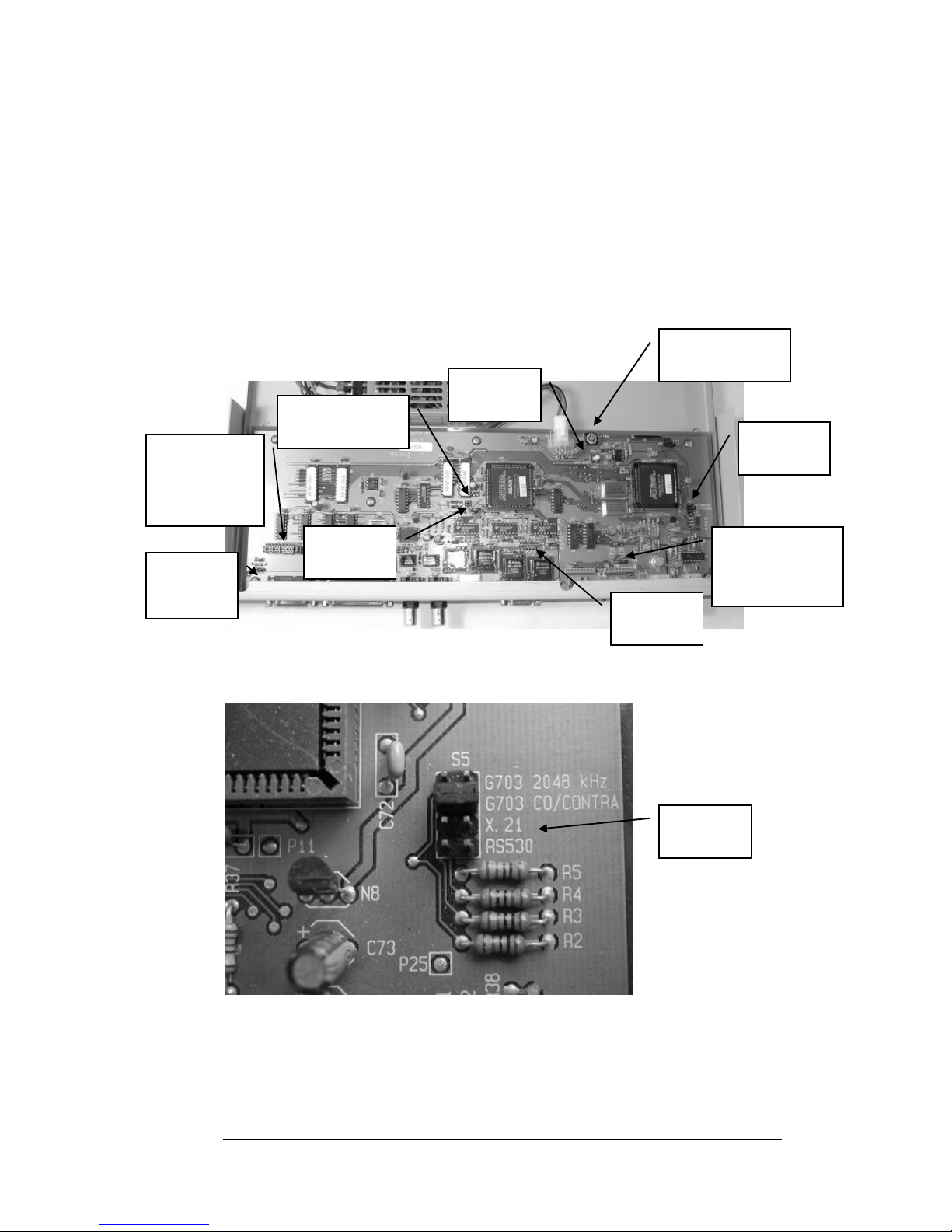
Configuration
Interface – S5
Codir/Contra – S6
Clock source – S14
Clock speed/data rate – S11
Synchronization of clocks – S13
Contra clock mode – S7, S8 and S8
X.21 DTE or DCE pinning – S2, S3, S4, S15 and S16
Signal ground to Protective ground reference – S1
NOTE! Jumper S6 must always be set to either CO or CONTRA. It
may not be left open!
Type of interface
Select type of interface that shall be converted to fiber optic – S5
Four alternative interfaces selectable:
1. G.703, 2048kbps, (E1) – BNC connectors.
2. G.703 64kbps Codir / Contra - RJ45 or 9 pin D-sub connector.
3. X.21 – 15 pin D-sub connector.
4. RS530 – 25 pin D-sub connector. D-sub connector not mounted
on units produced after October 2006.
S5
Interface
S5
Interface
S6
CO/CONTRA
S13
H13 and H14
SYNC
S11
Clock Speed
Master
Reset
S2, S3, S4 ,
S15, S16
X.21
DTE/DCE
S1
SGND/
S7
TxC/RxC
S8, S9
TcC/RxC
Page 21
21
G.703 E1 2048kbps.
Data rate selector S11 shall be set to position 0, 2048kbps.
Codir – Contra, CO/CON
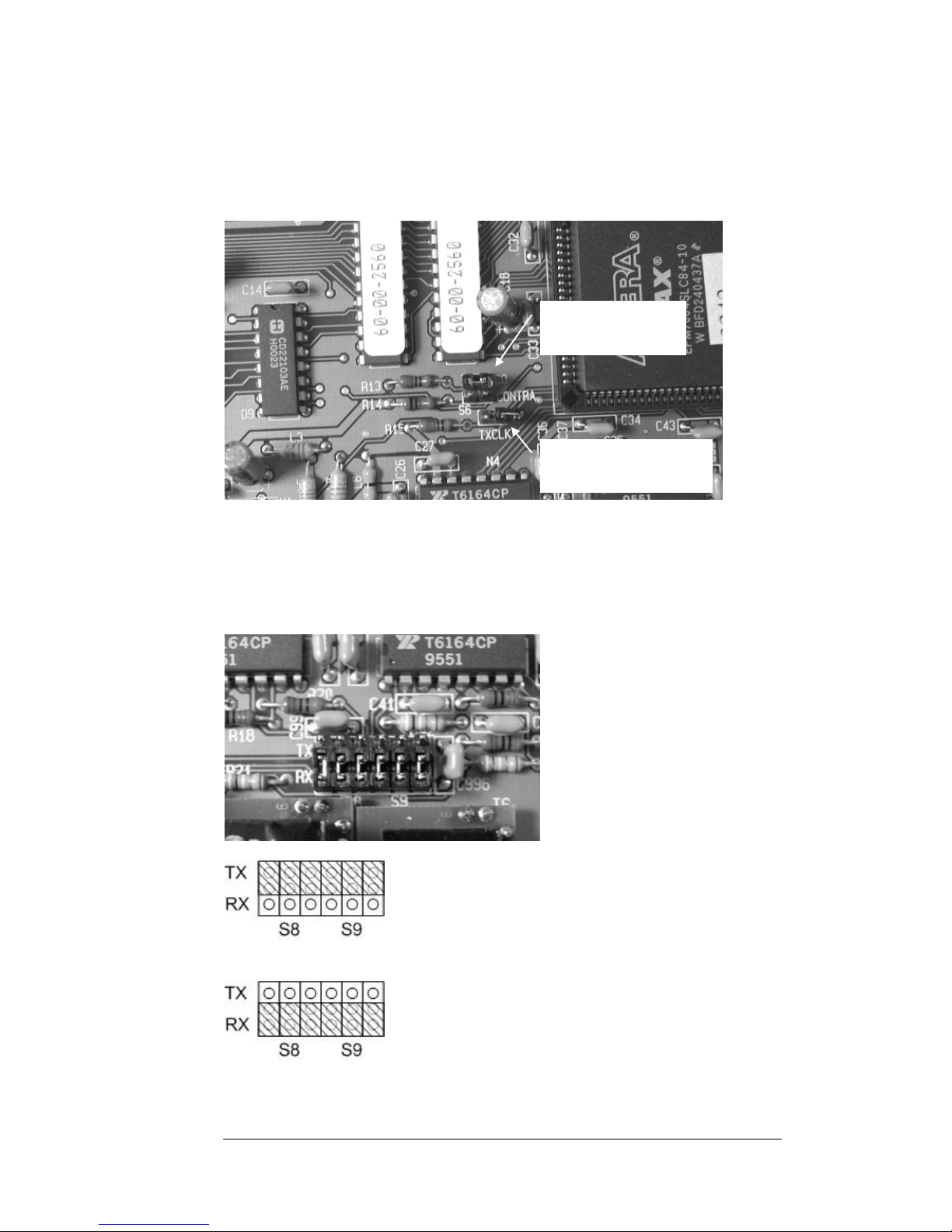
If S5 G.703 64kbps Codir/Contra is selected, select with S6 Codir or Contra.
S6 may NOT be left open!
Select c
lock mode for Contra
First with S7 select if 21-16xx shall transmit the receive and transmit clock.
Strap at S7 selects that 21-16xx transmit the receive and transmit clock.
No strap at S7 selects that 21-16xx receives the receive and transmit clock.
In addition S8 and S9 must be set according to S7 selection.
The 21-16xx transmit the receive and transmit clock.
21-16xx receives the receive and transmit clock.
S6
CO / CONTRA
S7
Contra clock mode
Page 22
22
Clock source.
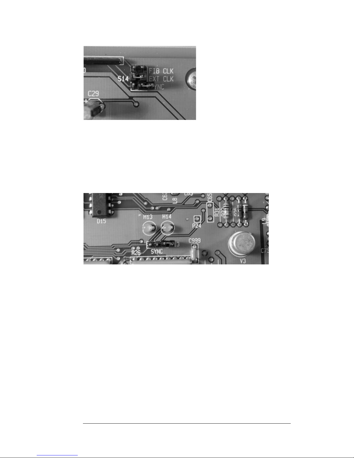
1. FIB CLK – Fiber clock. With strap, clock is extracted from incoming signal
on fiber.
2. EXT CLK – External clock. With strap clock is extracted from signal on
electrical interface.
3. Internal clock. No strap on FIB CLK and no strap on EXT CLK. Clock is
generated internally in 21.16xx.
4. SYNC - If the data received from the fiber needs to be synchronized in phase
with the data from the electrical interface, position a jumper at the SYNC
(lower) position of S14 and place the jumper S13 according to the brightest
LED, H13 – H14.
Internal clock – “Master mode”
When internal clock is selected, no straps on EXT CLK and FIB CLK, the clock used
is generated by an internal clock. This is used when two 21-16xx, (or other product
with same fiber protocol), are directly connected to each other. Only one 21-16xx
shall have this configuration.
If both local 21-16xx and remote 21-16xx has Internal Clock selected the link works
in Asynchronous mode. Only X.21 and RS530 interfaces support Asynchronous
mode. S11 shall be set to position 2048kbps. Maximum data rate is 256kbps in
asynchronous mode.
Page 23

23
Clock speed/data rate.
Select data rate with HEX-switch S11.
The different interfaces have individual possible selections:
Data rate
(kbps)
S11
position
G.703,
2Mbps
G.703
codir
G.703
contr
a
X.21 RS-530
2048 0, E, F OK - - OK OK
1536 1 - - - OK OK
1024 2 - - - OK OK
768 3 - - - OK OK
512 4 - - - OK OK
384 5 - - OK OK OK
256 6 - OK OK OK OK
192 7 - OK OK OK OK
128 8 - OK OK OK OK
64 9 - OK OK OK OK
38,4 A - - - OK OK
19,2 B - - - OK OK
9,6 C - - - OK OK
4,8 D - - - OK OK
NOTE! Regardless of the clock method, the data rate must be set
accordingly to the data rate used!
Page 24
24
X.21 mode.
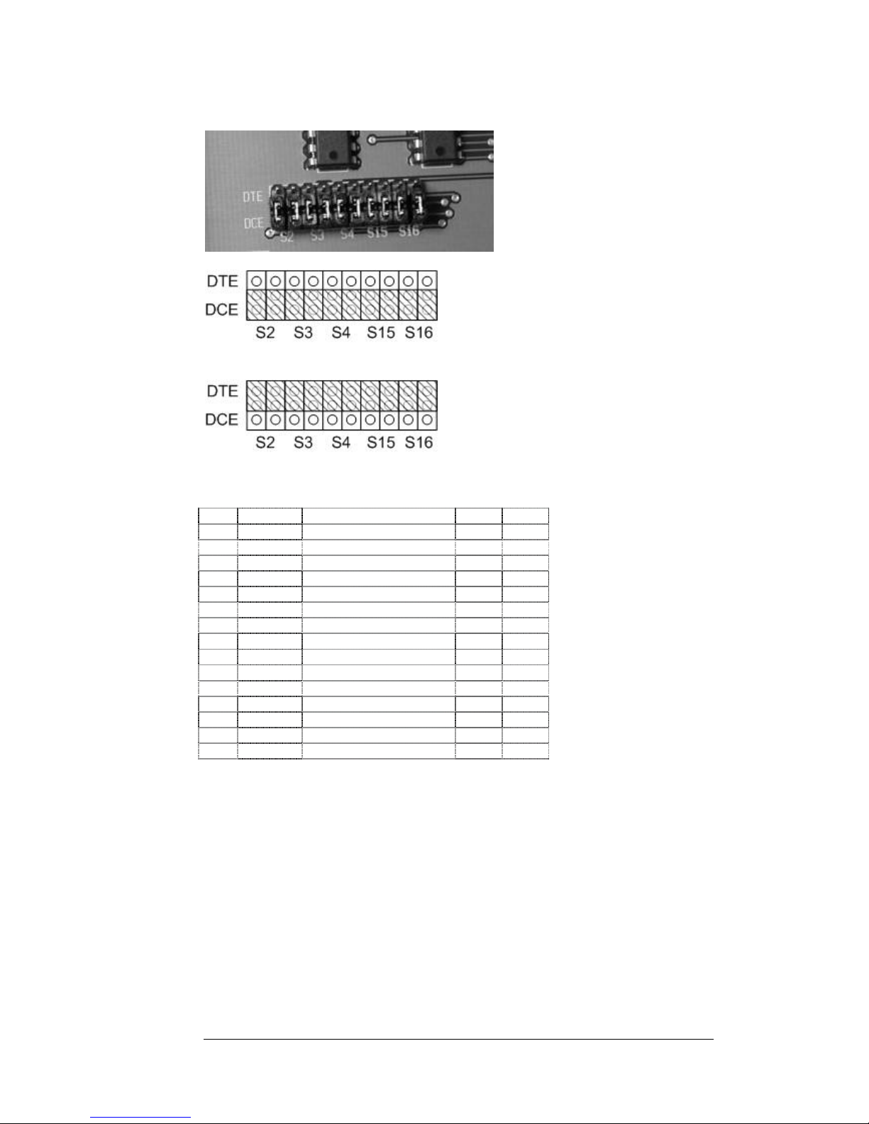
Select with S2, S3, S4, S15 and S16 the pinning of the 15 pin D-sub.
All straps in lower position Î DCE pinning.
All straps in upper position Î DTE pinning.
D-sub pinning
If both local 21-16xx and remote 21-16xx has Internal Clock selected the link works
in Asynchronous mode. S11 shall be set to position 2048kbps. Maximum data rate is
256kbps in asynchronous mode.
Pin Signal Function DTE DCE
1 Shield Shield – Chassies ground - 2 TxD A Transmit (A) Out In
3 Control (A) Out In
4 RxD A Receive (A) In Out
5 Indication (A) In Out
6 Signal Timing (A) In Out
7 - Unassigned - 8 SGND Signal Ground - 9 TxD B Transmit (B) Out In
10 Control (B) Out In
11 RxD B Receive (B) In Out
12 Indication (B) In Out
13 Signal Timing (B) In Out
14 - Unassigned - 15 - Unassigned - -
Page 25
25
RS530 mode.
Not available on units produced later than October 2006.
DTE or DCE function must be selected with pinning of cable connectors.
If both local 21-16xx and remote 21-16xx has Internal Clock selected the link works
in Asynchronous mode. S11 shall be set to position 2048kbps. Maximum data rate is
256kbps in asynchronous mode.
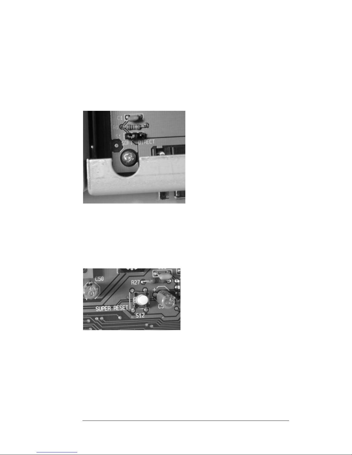
Ground selection.
Select Signal Ground – Chassie Ground relation.
SOFT Signal ground is referenced to Chassie ground with a resistor in
parallell with a condensator, (100kOhm and 100nF).
DIRECT Signal ground is connected direct to Chassie ground.
Strap left open No reference between Signal ground and Chassie Ground.
Super Reset.
If any selection is done with power on, the selection must be updated.
This is done by pressing SUPER RESET.
Page 26
26
Start and usage.
Power on.
Connect the power cord to the 21-1601 / 21-1651 and then connect to AC-mains or
DC-supply.
The “LO”-LED shall be lit green. If not, try to cross-connect the fibers at one end of
the link.
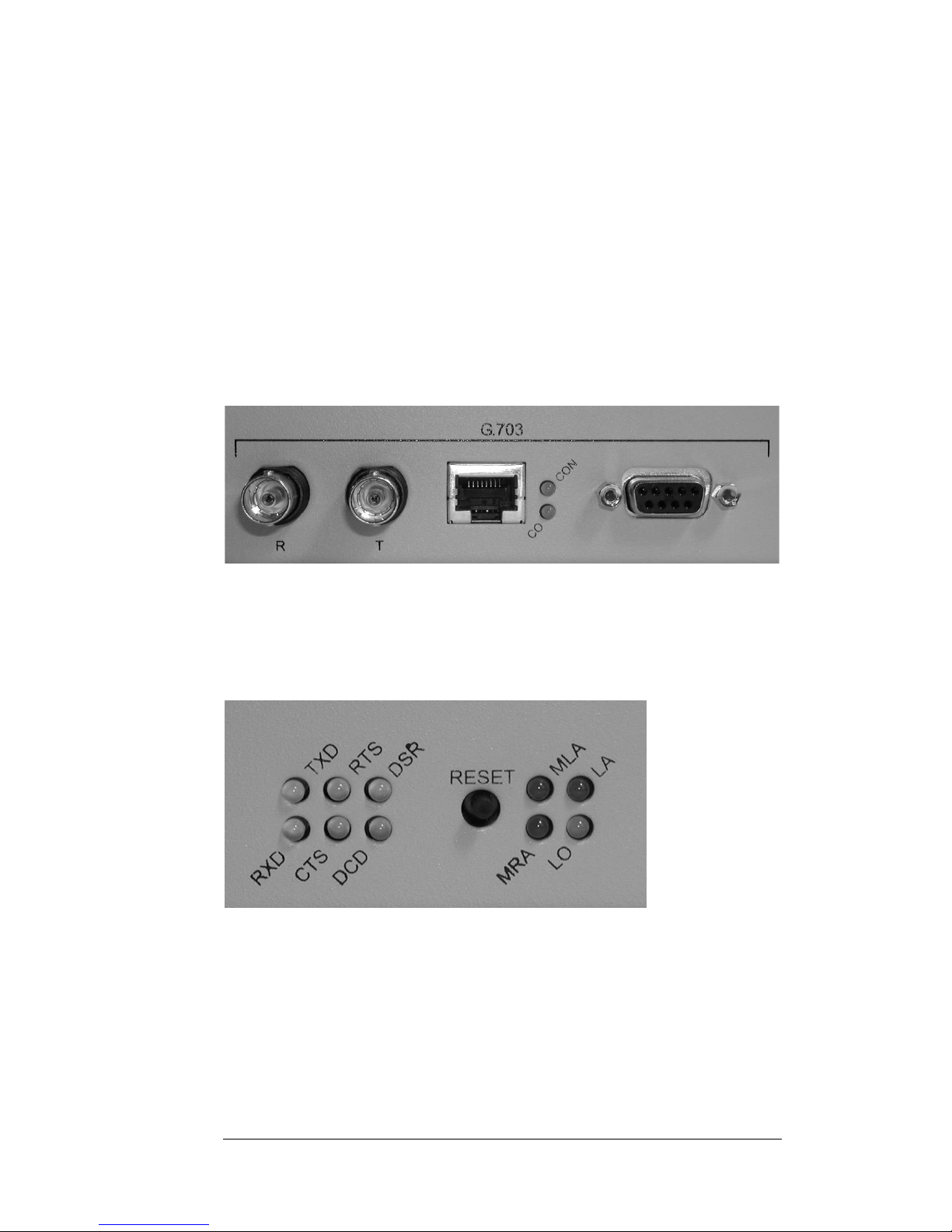
LED-status.
There are 12 LED-indicators at the front panel.
CON
A green LED is lit when Contra is selected.
CO
A green LED is lit when Codir is selected.
TXD
A yellow LED indicates data sent at selected electrical interface.
RXD
A yellow LED indicates data received at selected electrical interface.
RTS
A yellow LED indicate the status of RTS, (Ready To Send) on interface RS530 .
Page 27

27
CTS
A yellow LED indicate the status of CTS, (Clear To Send) on interface RS530 .
DSR
A yellow LED indicate the status of DSR, (Data Set Ready) on interface RS530 .
DCD
A yellow LED indicate the status of DCD, (Data Carrier Detect) on interface RS530.
LA
Local Alarm. Normally off. Is lit red if the fiber optic link monitoring has detected a
communication error on the incoming fiber.
MLA
Memory Local Alarm. Normally off/dark. This indication has the same function as
“LA” with an additional memory function. Is lit red if the unit has detected an “LA”error, and stays lit until the “Reset”-button is pressed.
MRA
Memory Remote Alarm. Normally off/dark. Is red if when the remote unit of the
fiber optic link has detected an error. This indication has a memory function. Any
remote error will be indicated until “Reset”-button is pressed.
LO
Link OK. Green when the fiber optic link is operating correctly.
Page 28

28
T echnical support
Before contacting technical support, we beg you to first read the manual once again..
If you still have problems or questions, don’t hesitate to contact help desk. Please
gather all relevant information, including serial number, about your installation before
contacting help desk.
Our technical support can be reached at:
Fibersystem AB
Gardsfogdevagen 18B
S-16866 Bromma
Sweden
Telephone: +46-8-564 828 80 • telefax: +46-8-28 33 50
Web:
E-mail addresses can be found on our web-site.
CE - mark
The product described in this manual, is designed to apply to the specifications of the
EMC directive 89/336/EEC and to low voltage directive 73/23/EEC
-:-
 Loading...