

FIBER SENSYS Fiber Defender FD348R User Manual

Fiber Defender
FD348R User Manual
Rev H
PM-ENG-011 Confidential – Limited Distribution

© Copyright 2014, Fiber SenSys® all rights reserved. No part of this publication may be
reproduced or transmitted in any form or by any means, electronic or mechanical, including
photocopy, recording, or any information storage and retrieval system, without permission in
writing from Fiber SenSys®, Inc., 2925 NW Aloclek Drive, Suite 120, Hillsboro, Oregon 97124,
USA.
This manual is provided by Fiber SenSys Inc. While reasonable efforts have been taken in the
preparation of this material to ensure its accuracy, Fiber SenSys Inc. makes no express or
implied warranties of any kind with regard to the documentation provided herein. Fiber SenSys
Inc. reserves the right to revise this publication and to make changes from time to time in the
content hereof without obligation of Fiber SenSys Inc. to notify any person or organization of
such revision or changes.
RK348™, FD348R
TM
is a trademark of Fiber SenSys Inc. (FSI)
Fiber SenSys® is a registered trademark of Fiber SenSys Inc.
Windows® is a registered trademark of Microsoft Corporation.
Fiber SenSys Inc.
2925 NW Aloclek Dr.
Suite 120
Hillsboro, OR 97124
USA
Tel: 1-503-692-4430
info@fibersensys.com
www.fibersensys.com
Page 2 Confidential – Limited Distribution

Contents
1. Introduction .......................................................................................................... 4
2. Safety information ................................................................................................ 6
Safety terms .................................................................................................... 6
Electrical safety ............................................................................................... 6
Covers and panels .......................................................................................... 7
Inspection ....................................................................................................... 7
Laser radiation ................................................................................................ 7
Fiber-handling precautions .............................................................................. 7
FCC rules ........................................................................................................ 8
3. The Sensing Fiber ............................................................................................... 9
Fiber Optic Sensing ......................................................................................... 9
Sensor
Insensitive Leads .......................................................................................... 10
Site Design and Installation ........................................................................... 10
Connectors ................................................................................................... 11
Cable
.................................................................................................. 9
4. The Alarm Processing Unit (APU) ...................................................................... 12
APU Description ............................................................................................ 12
Rack-Mount Chassis ..................................................................................... 15
RK348 Rear Panel Connections .................................................................... 17
5. SpectraView ...................................................................................................... 18
Using SpectraView ........................................................................................ 18
APU Parameter Editor Mode ......................................................................... 19
Realtime Mode .............................................................................................. 22
6. Integrating the APU into the Security System .................................................... 24
7. Testing and Certification .................................................................................... 25
8. Maintenance ...................................................................................................... 26
Appendix A. Product Specifications ................................................................ ........ 28
Appendix B. FD348R Menu Structure ..................................................................... 29
Appendix C. Warranty information .......................................................................... 38
Appendix D. Referenced Documents ....................................................................... 39
3

1. Introduction
The Fiber SenSys FD348R is a rack mountable electro-optical Instrument that uses
optical fiber as a distributed sensor for detecting intruders attempting to breach a
perimeter. The Alarm Processing Unit (APU) can be tuned to disregard non-threatening
stimulus such as wind and animals; thus, reducing nuisance alarms. When an intruder is
detected, the APU sends out an alert via IP/XML Ethernet communication as well as
state changes in terminal contacts that can be used to switch on lights, cameras, sirens,
or to signal an alarm panel. IP/XML communication for direct network interface allows for
easy integration with any security solution.
The optical fiber-based system has been designed to be
Electromagnetic Interference (EMI), lightning, and radio
FD348R provides maximum effective
flexibility and advanced programmability.
Because the fiber optic sensors use laser light which is intrinsically inert, the FD348R
system can be installed safely at chemical or ammunition depots, or any location where
the use of electricity is a concern.
RS-232 communication allows for simple setup and calibration.
A key component of the FD348R is its fiber optic sensor cable; this uniquely-designed
cable, which is sensitive to movement, pressure, and vibration, can be routed along the
fabric of a fence to detect climbing and cutting. The detection of an intruder triggers an
alarm from the Alarm Processing Unit (APU).
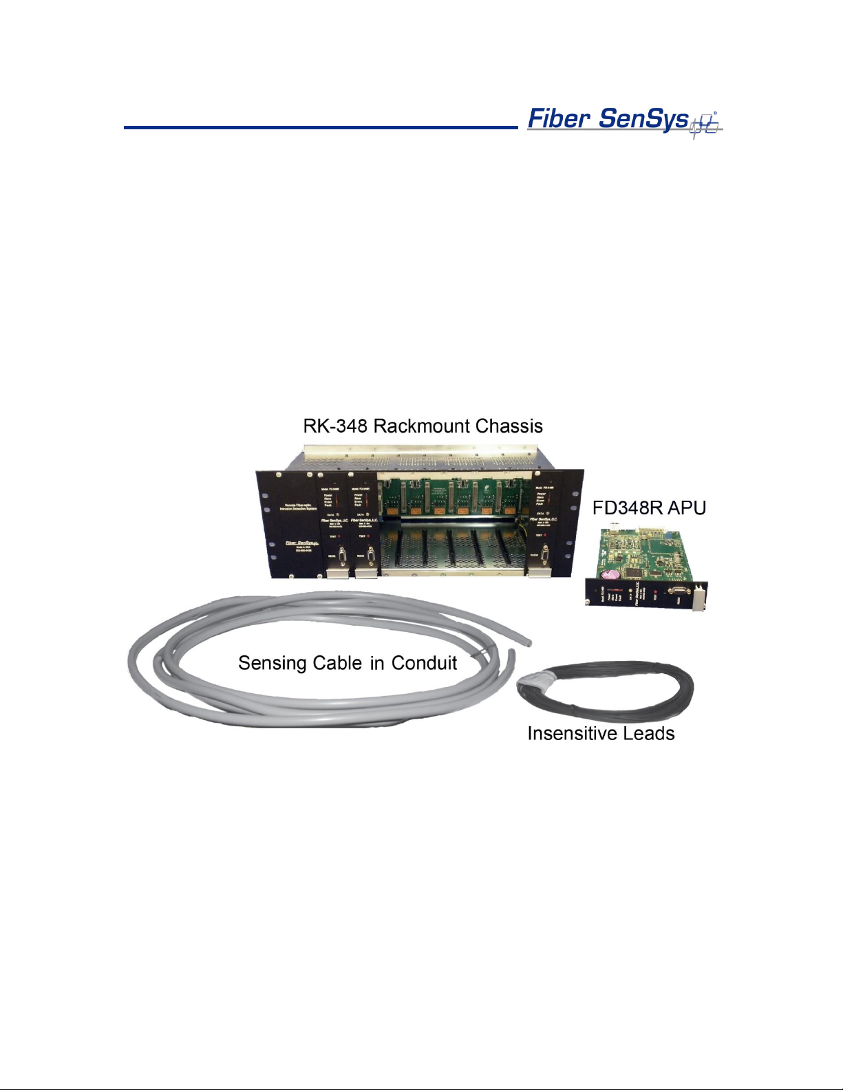
Another key feature of the FD348R is its use of insensitive lead-in cables, allowing each
APU (up to 8 in one RK348 rack) to be mounted up to 20 kilometers (12.4 miles) away
from the protected zone. This feature lets the user install the APU in a location that is
close to power and communications as well as secure from weather.
The FD348R is designed to be installed in the RK348, a 19 inch rack-mount chassis that
houses and provides power for up to eight individual FD348R APUs. Each APU monitors
a separate zone, allowing for up to 8 separate zones to be independently monitored from
one rack mountable module.
intrusion
detection through its inherent system
immune
frequency
to the effects of
emissions. The
4
Some of the intrusion threats the FD348R can be used to detect include:
Fence climbing (along both the fabric and post)
Fabric cutting
Crawling underneath a fence
Ladder assisted climbing of a fence
A single run of
miles) in length.
sensor
cable can protect a zone up to 5 kilometers (16,400 feet/3.1
Figure 1-2. Complete FD348R System
5

2. Safety information
This section contains information to help ensure your personal safety and the proper
operation of your equipment. Please read and follow all these instructions carefully, and
keep them accessible, for future reference. Whenever using the FD348R, use only
attachments and accessories that have been specified by FSI, and refer all servicing to
qualified personnel.
Safety terms
The following icons may appear throughout this manual:
CAUTION: Identifies conditions or practices that could result in damage to
equipment and/or loss/contamination of data.
WARNING: Identifies conditions or practices that could result in non-fatal
personal injury.
DANGER: Identifies conditions or practices that could result in serious injury
or death.
Electrical safety
If the FD348R APU is damaged or malfunctions, disconnect power to the APU. Do not
use the APU if any of the following conditions exist:
• The APU is visibly damaged.
• The APU does not operate as expected.
• The APU has been subjected to prolonged storage under adverse conditions.
• The APU has been damaged during shipment.
Do not put the APU into service until qualified service personnel have verified its safety.
6

Covers and panels
There are no user-serviceable parts inside the APU. To avoid personal injury, do not
remove any of the APU’s covers or panels. The product warranty is void if the factory
seal is broken. Do not operate the product unless the covers and panels are installed.
Inspection
The FD348R APU should be inspected for shipping damage. If any damage is found,
notify Fiber SenSys and file a claim with the carrier. Save the shipping container for
possible inspection by the carrier.
Laser radiation
The FD348R APU is a Class I laser product, as defined by IEC 60825-1 and CFR 21
subchapter J. A Class I laser product emits insufficient laser radiation to constitute a
hazard. However, avoid direct eye exposure to the output of this product or to the open
end of any optical-fiber cable connected to this product.
Fiber-handling precautions
Optical fibers are made of glass, and the ends of a broken fiber can be sharp and
may become lodged in the skin. Take appropriate glass-handling precautions.
7

FCC rules
Note: This equipment has been tested and found to comply with the limits for a
Class B digital device, pursuant to Part 15 of the FCC Rules. These limits are
designed to provide reasonable protection against harmful interference in a
residential installation. This equipment generates, uses, and can radiate radio
frequency energy. If the equipment is not installed and used in accordance with the
instructions it may cause harmful interference to radio communications. However,
there is no guarantee that interference will not occur in a particular installation. If this
equipment does cause harmful interference to radio or television reception, which
can be determined by turning the equipment off and on, the user is encouraged to
try to correct the interference by one or more of the following measures:
• Reorient or relocate the receiving antenna.
• Increase the separation between the equipment and receiver.
• Connect the equipment into an outlet on a circuit different from that to which the
receiver is connected.
• Consult the dealer or an experienced radio/TV technician for help.
8

3. The Sensing Fiber
The FD348R detects intruders by sensing small disturbances caused by vibrations
induced within a fiber optic sensor attached to the perimeter. The optical sensor is a thin
strand of multimode optical fiber. The fiber optic cable is installed in such a way that,
when intruders attempt to cross the perimeter, they create slight vibrations that disturb
the sensing fiber. These disturbances are then detected by the FD348R APU, which
generates the appropriate alarm(s).
Fiber Optic Sensing
When an optical fiber is exposed to vibration, the disturbance causes small asymmetric
changes in the fiber’s density. In turn, these changes in density cause measurable
changes in certain characteristics of laser radiation transmitted through the fiber. The
FD348R uses precision lasers and detectors, along with sophisticated digital signal
processing, to measure changes in the laser radiation. The processor analyzes the
incoming signals in order to determine whether they are caused by intruders, or
harmless nuisances, such as vibrating equipment. To learn more about fiber optics and
their use as sensors, refer to the application note on fiber optics titled: AN-SM-007 Fiber
Optics.
Sensor
There are two types of sensor cable for the FD348R: SC-3 and SC-4.
SC-3 is distinguished by its dark
is resistant to
contained within protective conduit.
•
Sensor cable comes in varying
•
Cable in conduit should be purchased in premeasured zone lengths and reels can be up
to 800 meters.
Cable
weather, dirt,
SC-3 (brown
SC3-C (cable in conduit
jacket) – 3 mm sensor cable used for perimeter
etc. although the cable is not outdoor rated and should be
brown
lengths, with up to 2000 meters (6500 feet)
) – 3 mm sensor cable within grey ½” UV rated conduit.
protective jacket. This jacket ensures the cable
applications.
per
spool.
9

SC-4
comes in a thicker green jacket and is outdoor rated. This cable can be attached
to the fence directly using nylon cable ties and does not need to be deployed within
protective conduit.
•
SC-4 (green jacket)
- 4 mm sensor cable used for perimeter applications.
Sensor cable comes in varying
lengths
with up to 2000 meters (6500 feet)
per
spool.
Insensitive Leads
The insensitive leads, so named because they are unaffected by vibrations, are singlemode type optical cables. Fiber SenSys offers several single-mode cable configurations
to satisfy a wide range of system implementations. Like the sensor cable, the insensitive
leads are made of optical fiber that is immune to RF and EMI energy. The insensitive
leads are also weather resistant. These leads are used to transmit light from the APU to
the sensor cable mounted in the protection zone and back again.
Site Design and Installation
There are many different ways to use the FD348R system. The most common
installation is on chain link fence. For fence-mounted applications the fiber optic cable is
installed inside a flexible conduit which is then secured to the fence using stainless steel
wire ties. Other applications involve installing the optical cable inside the channels of
decorative metal fence or running the flexible conduit (with optical cable inside) along the
tops of concrete walls.
Ultimately, the method by which the FD348R system is deployed is up to the end user;
Fiber
however, the general procedure for installing the FD348R system is:
10
SenSys does not mandate one particular installation setup
1. Assess: Survey the site to be protected and record all information needed
for the site design phase.
2. Design: Create a strategy for protecting the site. This includes planning
the level of security, choosing the location of the APUs, provision of
electrical power, and planning cable routing.
3. Install: Proper deployment of the fiber optic sensor and correct installation
of the Fiber SenSys system.
over
another;

To learn more about sensing fiber installations, refer to the application note on
installation: AN-ENG-027 Site Design and Installation for FD300 Series.
Connectors
To maintain a high signal-to-noise ratio, it is important that all connections within a given
fiber optic sensor (zone) be made by either fusion splicing or by physical-contact fiber
optic connectors (PC). It is helpful to test the optical loss of each zone. The insensitive
lead-in fibers plug directly into the APU and are always connected with an ST connector
(ST/PC). The insensitive leads are spliced, or coupled via ST/PC feedthrough connector,
to the sensing fibers.
Note: It is important that only clean optical connectors are inserted into the APU’s
optical inputs and outputs; dirty connectors can degrade the performance of the
APU or even cause irreversible damage. When leaving connectors unconnected
make sure they have protective caps installed on the ferrules. Caps protect the
ferrule from damage that might be caused by bumping the ferrule against a foreign
object. However, when caps are dirty they don’t protect (effectively) against
microscopic contamination. Consequently, be sure to clean all connectors prior to
insertion whether or not they have been capped. For more information on the care
and cleaning of fiber-optic connectors, refer to the application note on fiber optics:
AN-SM-007 Fiber Optics.
11
Front
Indicators
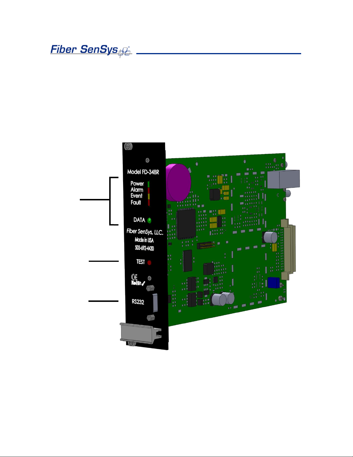
Test Button
RS-232 Port
4. The Alarm Processing Unit (APU)
APU Description
The FD348R APU is a module containing a laser, optical detector, and the electronics
for processing return optical signals. The APU has 4
optical connectors, "Input" and "Output" as well as an RS-232 connector and Ethernet
connector.
input/output
ports. There are
2
Figure 4-1. The FD348R front view with labeled connectors
The front panel of the APU has an RS-232 connector for connecting to a PC during
tuning. The pin-out for the RS-232 connector is shown in figure 4-2 and table 4-2.
12
 Loading...