

Fiberpool BC, BCP Handbook For Use And Maintenance
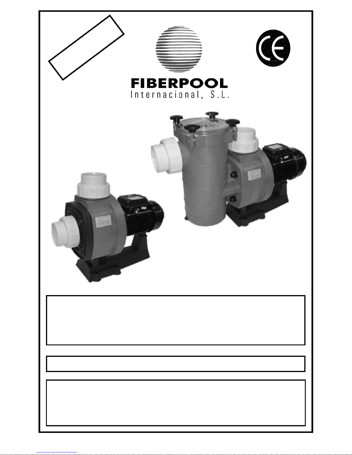
ELECTROBOMBAS PARA PISCINAS
ELECTROPUMPS FOR SWIMMING POOL
ELECTROPOMPES POUR PISCINES
MANUAL DE INSTRUCCIONES PARA EL USO Y MANTENIMIENTO
MANUEL D’INSTRUCTIONS POUR L’UTILISATION ET
L’ENTRETIEN
HANDBOOK FOR USE AND MAINTENANCE
MODELO BC / BCP
Y
E
A
R
S
O
F
G
U
A
R
A
N
T
E
E
A
Ñ
O
S
D
E
G
A
R
A
N
T
I
A
A
N
N
É
E
S
D
E
G
A
R
A
N
T
I
E
2
FIBERPOOL INTERNACIONAL
4- EMBALAJE, TRANSPORTE Y ALMACENAMIENTO.
4.1
ATENCIÓN. El fabricante suministra el equipo protegido
con el embalaje adecuado, para transportarlo, almacen arlo y
que no sufra daños que impidan su correcta instalación y/o
funcionamiento.
4.2 ATENCIÓN. El usuario, a la recepción del equipo,
comprobará inicialmente estos puntos:
- Estado de embalaje exterior, si presenta signos de
deterioros importantes, lo hará constar formalmente a
quien se lo entrega.
- Verificará también el estado del contenido; y si éste
presentase desperfectos que presumiblemente
impidiesen su correcto funcionamiento, lo
comunicará, también formalmente, al proveedor en
un plazo máximo de 8 días desde el de la recepción.
4.3 ATENCIÓN. Las condiciones de almacenamiento serán
tales que garanticen el buen estado de conservación del
equipo. Señalamos por su especial importancia las de evitar
ambientes de humedad acusada u otros donde puedan
producirse cambios bruscos de temperaturas (producen
condensaciones).
5- INSTALACIÓN Y MONTAJE.
5.1 Emplazamiento.
ATENCIÓN. El lugar de instalación de la
motobomba tiene que ser seco. En cualquier caso debe existir
un desagüe en el suelo como protección contra inundaciones.
Si se monta la bomba en un local húmedo, habrá que prever
un sistema de ventilación para evitar la formación de agua de
condensación. En el caso de montajes en espacios muy
reducidos, el enfriamiento del aire puede ser tan bajo que sea
necesario un sistema de aireación y desaireación (ventilación)
con el fin de no exceder la temperatura ambiente de 40ºC
(BC)-50ºC (BCP). Es importante que la reserva de espacio sea
suficiente para poder desmontar el bloque motor en sentido
horizontal y el filtro de cabellos en sentido vertical (véase
dibujo de espacio mínimo en Fig. 1, pag. 11).
5.2 Localización/ instalación.
ATENCION. El equipo o
conjunto del grupo motobomba, filtro y válvula selectora, se
instalará cerca de la piscina a una distancia no superior a 3m
de las tomas de superficie (skimmer/ rebosadero) y
preferentemente a una cota de 0.5m (nunca superior a 3m)
bajo el nivel del agua, para conseguir su funcionamie nto “en
carga”. La unión de la válvula selectora y de ésta con la
boquilla y demás accesorios empotrados en la piscina se
realizará prioritariamente en tubería de P.V.C. El diámetro de
las tuberías dependerá de los caudales. La velocidad máxima
aconsejable del agua en las tuberías ha de ser de 1.2m/s en
aspiración y de 2m/s en el retorno. En cualquier caso, el
diámetro de la tubería de aspiración no debe ser inferior al
diámetro de la boca de la bomba. La tubería de aspiración
debe ser perfectamente estanca y se ha de instalar con una
pendiente descendiente (no inferior a 1/100), evitando de este
modo la formación de bolsas de aire. En instalaciones
permanentes, con la bomba situada en planos superiores al
nivel de agua, se procurará que la tubería de aspirac ión en su
máximo recorrido esté por debajo de los planos mencionados
hasta alcanzar la vertical coincidente con el eje de aspiración
de la bomba. La tubería de aspiración puede ser rígida o
flexible con espiral de refuerzo que evite la contracción. En
instalaciones fijas, con la bomba por debajo del nivel del agua,
se colocará una válvula de cierre en aspiración y otra en
impulsión.
5.3 Conexión eléctrica. ATENCIÓN. Con carácter
general, la instalación eléctrica estará, en todo de acuerdo con
lo preescrito en los Reglamentos y Disposiciones Técnicas
Complementarias que se dan a continuación y lo hará un
instalador autorizado. La red de alimentación dispondrá de
conductores de neutro y tierra. La tensión de la red ti ene que
corresponder con la dada en la placa de características del
equipo. La sección de los conductores a utilizar tiene que ser
suficiente para soportar, sin deterioro, la intensidad absorbida
por el equipo (ver placa de características). Al conductor de
tierra de la red se unirán eléctricamente todas las partes
metálicas del equipo que no deben estar bajo tensión, pero
que accidentalmente pudieran llegar a estarlo y sean
accesibles a las personas (ver Fig.2,3,4 Págs.11-12). Es
obligatoria la instalación de un cuadro eléctrico d e pr otecci ón y
maniobra en la que se sitúan todos los elementos exigidos y
otros recomendados. Con carácter general dispondrá de :
a. Interruptor general de corte unipolar.
b. Dispositivos de protección contra cortacircuitos y
sobrecargas en los motores.
c. Interruptor diferencial de alta sensibilidad, 30 mA.
d. Otros, de mando y control.
Las características eléctricas de los dispositivos de protección
y su regulación, estarán de acuerdo con la s de los motores a
proteger y con las condiciones de servicio previstas por el
fabricante (ver placa de características).
- En equipos con motores trifásicos hay que posicion ar
adecuadamente los puentes de interconexiones de
los devanados del motor, (ver Fig. 3,4 Pág. 12)
- La entrada y salida de conductores a la caja de
bornes se hará mediante prensaestopas que
garantizan la ausencia de humedad y suciedad en
ésta, por lo que estará provista de un cierre estanco.
- Los conductores para su unión a bornes, estarán
dotados de terminales adecuados.
6- PUESTA EN MARCHA.
Antes de poner el equipo bajo tensión, conectado a l a
red, se harán las siguientes operaciones:
- Verificar que las condiciones eléctricas sean
correctas.
- Comprobar, manualmente que la motobomba no esté
agarrotada.
6.1 Cebado de bomba
PARA BOMBAS BC. ATENCIÓN.
Con la bomba por debajo del nivel del agua, llenar la bomba
abriendo lentamente la válvula de cierre de aspiración,
teniendo abierta la válvula situada en su impulsión.
Con la bomba por encima del nivel del agua, llenar la bom ba
por la parte superior, abriendo la válvula de cierre de
aspiración hasta haber llenado por completo tanto la tubería
de aspiración como el cuerpo de bomba.
6.1 Cebado de bomba
PARA BOMBAS BCP. ATENCIÓN.
Evitar el funcionamiento en seco de la electro bomba.
Con la bomba en aspiración (por encim a del nivel del agua de
la piscina), antes de la puesta en marcha, retirar la tapa
prefiltro bomba (pag. 17 nº16) y llenar lentamente con agua
limpia hasta el nivel de la boca de aspiraci ón. Cerrar la tapa
3
FIBERPOOL INTERNACIONAL
(16) de nuevo y tomar la precaución que esté herméticament e
cerrada.
ATENCIÓN.
Con la bomba por debajo del nivel del agua de la piscina,
siempre con la tapa (16) herméticamente cerrada, llenar la
bomba abriendo lentamente la válvula de cierre de aspiración,
teniendo abierta la válvula situada en impulsión.
6.2
ATENCIÓN.
Evitar el funcionamiento en seco de la electro bomba.
Para mod. BCP: no se debe poner la bomba en marcha sin el
cestillo (18) ya que, de esta manera, podría obstruirse y
quedar bloqueada.
6.3 Sentido de giro.
ATENCIÓN. Asegurarse que el eje del
motor gira libremente, no poner en marcha si está bloqueado.
Para este fin, las electro bombas tienen una ranura en el
extremo del eje, lado ventilador, que permite hacerlo girar a
mano con un destornillador. Fig.1 (Pág. 11). En los motores
trifásicos la turbina (pag. 16-17 nº8) pueden destornillarse si el
motor arranca en sentido contrario. La rotación inversa puede
también incluso dañar el sello mecánico. Arrancar pocos
segundos el motor y controlar que el sentido de rotación
corresponde al indicado en la flecha situada en la tapa del
ventilador. Si no fuera así, es imprescindible avisar a un
instalador autorizado (invertir la conexión de fases entre ellas).
6.4
ATENCIÓN. Comprobar que el motor no supere el
amperaje indicado en la placa de características, en caso
contrario regular con la válvula situada en impulsión.
Evitaremos el funcionamiento prolongado de la electro bom ba:
descebada, con la válvula cerrada o por falta de agua en
aspiración.
7. MANTENIMIENTO / CONSERVACIÓN.
Antes de cualquier manipulación, desconectar la
alimentación eléctrica.
7.1 Modelo BCP
ATENCIÓN.
Controlar y limpiar periódicamente el cestill o (pag.17 nº18) de
la bomba.
Para extraer el cestillo situar la válvula selectora en la posición
de “cerrado”, así como todas las demás válvulas del colector.
Soltar la tapa (16) del prefiltro de bomba, extraer el cestill o y
limpiarlo bajo un grifo de agua, no golpear para evitar su
deterioro. Para ubicar nuevamente el cestillo introducirlo
suavemente, hasta dejarlo en su posición primitiva. Colocar
bien la junta (17) de la tapa y engrasarla con vaselina.
La tapa transparente se limpiará con agua y jabón neutro; “no
utilizar disolventes”. No introducir en el filtro productos
químicos.
No olvidar que los cambios de posición de la válvul a selectora
se realizan siempre con el motor parado.
7.1 Modelo BC.
ATENCIÓN.
Si la bomba permanece parada por períodos largos, o si
existiese peligro de heladas, se debe vaciar el cuerpo
hidráulico (pag 16, , nº5), soltando el tapón (14) de vaciado
con su junta tórica (14). Antes de poner en marcha la bomba,
colocar el tapón con su tórica. Llenar de agua la bomba y
comprobar con un destornillador que el motor no está
bloqueado (fig 1, pag.11). Se el eje estuviese agarrotado,
avisar a un técnico cualificado.
En caso de inundación del motor, no intentar ponerlo en
marcha, se avisará a un electrotécnico, y éste desmontará el
motor para proceder al secado del mismo.
7.2
ATENCIÓN. Si la bomba permanece parada por los
períodos largos, o si existe peligro de heladas, se debe
vaciar el cuerpo de la bomba (7,TT-5,TR), soltando los
dos tapones (6) de vaciado con sus juntas tóricas . Antes
de poner en marcha la bomba, colocar los tapones (6) con
sus tóricas . Llenar de agua el cuerpo de bomba y
comprobar con un destornillador que el motor no está
bloqueado. Si el eje estuviese agarrotado, avisar a un
técnico cualificado. En caso de inundación del m otor, no
intentar ponerlo en marcha; se avisará a un
electrotécnico, y éste desmontará el motor para proceder
al secado del mismo.
8. DESMONTAJE
8.1 ATENCIÓN. Antes de cualquier operación,
todas las válvulas deben estar cerradas, comprobando esto
procederemos a:
-Desconectar el interruptor general eléctrico e interruptor
diferencial (a realizar por especialista autorizado).
Soltar y retirar los cables de alimentación de la caja de bornes
-Liberar los manguitos de aspiración y retorno
-Vaciar la bomba.
8.2
ATENCIÓN. Para desmontar y montar la electro bomba
ver plano de despiece (pag. 16-17).
Para separar el motor del cuerpo hidráulico, quitaremos los
seis tornillos y los dos tornillos, extraeremos el conjunto motor
con la turbina (9).
Para desmontar la turbina (9), quitaremos el tornillo y su junta ,
utilizando la llave allen del nº8, queda de esta forma liberad a
la turbina (9). Al efectuar esta operación quedará también
liberada la parte móvil del retén. El difusor (8) ya esta liberado.
9. MONTAJE.
ATENCIÓN. Todas las piezas que vayamos a acoplar
deben estar limpias y en perfectas condiciones de uso.
Para el montaje de la bomba procederemos:
- Montar el sello mecánico (pag 16-17 nº10-11)
ensamblar la parte giratoria del sello (10) sobre el
saliente posterior de la turbina (13) presionand o esta
hasta encajar en el alojamiento, de esta forma se
consigue la unión de las dos pistas del sello
mecánico. Previamente habremos lubricado el retén
con agua
- Ensamblar la turbina (9) en el eje fijando esta
mediante tornillo y su junta utilizando llave allen nº8.
- En la unión de la bomba con el motor hemos de
tener en cuenta que los resalte del difusor (8) encaje
en el alojamiento adecuado, igualmente que las
juntas (7,12).
10. RECAMBIOS
Para la solicitud de cualquier pieza de recambio, precisar la
denominación, el número de posición en el plano de des piece
(pag 16 a 23) y los datos de las placas de características
1. DESCRIPTION
4
FIBERPOOL INTERNACIONAL
1.1 These electropumps have been designed to recirculate
lightly treated water in swimming pools and spas, both private
and public.
1.2 Technical characteristics
Motor:
Power ratings: See nameplate ratings on electropump.
Insulation: Class E.
Operation: Continuous.
Protection: IP 54.
Current: Single phase and triphase (see nameplate ratings).
Consumption: See nameplate ratings.
Frequency: See nameplate ratings.
R.P.M: See nameplate ratings.
Shaft: Stainless steel.
Bearing: Armoured ball bearing.
Atmospheric temperature: Maximum 40ºC (BC) 50ºC (BCP).
Pump:
Water temperature: Max 50ºC
Maximum pressure: 2 BARS
Impeller model: Closed
Type of seal: Mechanical retainer.
Diffuser : Synthetic material (PP)
Impeller : Noryl with Fiber Glass
Pump Casing : Synthetic material (PP)
Filter lid for BCP model : Synthetic material
Aspiration diameter : Socket 90mm
Impelling diameter : Socket 90mm
2. GENERAL
2.1 Introduction
This handbook contains the necessary instructions for
installation, use and maintenance of the swimming pool
electropump. In order to obtain the maximum yield shown b y
the manufacturer in the Description of Characteristics, it is
necessary to fulfil and follow correctly all the recommendations
given in this-Handbook. This will allow operation with a safe
and long-lasting piece of equipment. The equipment supplier
will furnish the user with complementary information, if
required.
2.2-Safety signs used in the handbook.
All instructions referring to possible risks to persons are
highlighted by the followings symbols:
Other instructions in relation to the functioning of the
equipment with which non-compliance could cause physical
damages are highlighted with the warning:
ATTENTION
2.3 Nameplate ratings (EEC 89/392 P.1.7.4.A.) The
information given on the nameplate or other instructions affixed
by the manufacturer to the unit, must be strictly complied with.
The content of these plates can usually be found in this
Handbook (Chapter 1.2).
2.4 Liability. Failure to comply with the instructions given by
manufacturer in this handbook, in relation to the choice,
handling, installation, starting and maintenance of the unit,
shall release the manufacturer or distributor from all liability in
respect of accidents suffered by persons or damages caused
to other installations and, in addition, shall entail forfait of the
warranty.
2.5 Standard. Our swimming pool electropumps are
manufactured in accordance with the necessary requirements
for safety and health set forth in Community Directives
89/392/EEC, 91/368/EEC (assimilated into Spanish Law by
Royal Decrees, 1435/1992 and 93/44/EEC).
3 GENERAL INSTRUCTIONS IN RELATION TO USER
SAFETY.
3.1 Safety during operation of the machinery supplied
can only be guaranteed if it is used in accordance with the
diagrams show n on page 11-12 “Illustrations”. It must never
exceed the working conditions and limits given in this
Handbook (chapter 1.2 – Technical Characteristics).
Compliance with the provisions of Safety Standards in force in
each country is mandatory.
3.2 Please ensure that the equipment selected is
adequate for the use for which it is intended and that its
condition, installation, starting and subsequent use are correct.
See chapter 1 (Technical Characteristics).
3.3 Installation, repair and maintenance operations will
be carried out in all cases with equipment disconnected from
the mains.
3.4 While the equipment is functioning, it cannot be
moved or repositioned. These operations will be carried out at
all times with the machine disconnected.
3.5 Pressing of the electrical on/off or safety elements
will not be performed where there is damp, and special c are
must be taken for user’s hands to be dry, and also with
footwear and surfaces with which the user is in contact.
3.6 Those elements of the equipment which, when
functioning, are in movement or which could reach danger ous
temperatures, will be protected with cages or casings which
will prevent accidental contact with the same.
Standard DIN 4844-W9
Dan
g
er in general
3.7 Electricity conductors, or parts which could carry
current, will be suitably insulated. Other metal parts of the
equipment will be correctly earthen.
3.8 Spare parts that may be necessary will be originals
from the manufacturer or those recommended by the
manufacturer. The use of others, or originals rectified by
others, are not permitted and release the manufacturer or
distributor from all liability.
Standard DIN 4844-W8
Dan
g
er of electrocution.
4 PACKING, TRANSPORT AND STORAGE
4.1
ATTENTION. The manufactured supplies the equipment
protected in suitable packaging, so that it is not damaged
during transport or storage thus preventing its correct
installation and/or functioning.
5
FIBERPOOL INTERNACIONAL
4.2 ATTENTION. The user, upon r eceipt of the equipment, will
immediately check the following points:
- Condition of the outside packaging, if this shows
signs of serious deterioration, he shall formally advis e
the person delivering the equipment.
- He shall also check the condition of the contents:
should this show defects which would presumably
prevent correct functioning, he shall also formally
notify the supplier within a period not exceeding 8
days from the date of delivery.
4.3
ATTENTION. Storage conditions must ensure the optimum
preservation of the equipment. Due to its particular relevance,
we must stress that very damp atmosphere or others where
brusque changes in temperatures (which cause condensation )
must be avoided.
5. INSTALLATION AND ASSEMBLY
5.1 Location. ATTENTION. The place where the electropump
is to be located must be dry. In all events, there must be a
drain in the floor as prevention against flooding. If the pump is
to be located in a damp place, a ventilation system must be
provided in order to prevent the formation of condensation. In
the case of very confined areas, cold air can reach a low
temperature which requires a ventilation system where by the
atmospheric temperature does not exceed 40ºC. (BC) –
50ºC.(BCP). It's important for there to be sufficient space to
permit the motor block to be dismounted horizontally and the
hair filter vertically (see minimum space diagram in fig. 1, page
11.
5.2 Positioning /installation
ATTENTION. The equipment or set of motor pump, filter and
selection valve, will be installed near the swimming pool at a
distance of no more than 3 m, from the surface skimmers and
preferably at the level of 0.5m (never more that 3m) below the
level of the water in order to achieve its “under load”
functioning. The selection valve junction, and its connection to
the nozzle and other accessories incorporated in the swimming
pool will preferably be made in PVC casing. Pipe diameters will
depend on flows. The maximum water speed a dvisable in the
pipes will be 1.2 m/s in aspiration and 2 m/s on return. In any
event, the diameter of the aspiration of the aspiration pipe
must not be less than diameter of the pump nozzle. The
aspiration pipe must be perfectly watertight and must be
installed with a downward inclination, thus avoiding the
formation of air pockets. In permanent installations, with the
pump positioned at a higher level than that of the water, it is
advisable for the longest stretch of the aspiration pipe to be
below the plans mentioned until it reaches the vertical pipe
which coincides with the pump aspiration shaft. The aspiration
pipe can be either rigid or flexible with a reinforced coil to av oid
contraction.
In fixed installations, with the pump below the water level, a
shut-off valve will be placed on the aspiration pipe and another
on the header pipe.
ATTENTION. When using as a portable pump,
suitable electrical protection must be provide and the pump
must be assembled on an insulated base.
5.3 Connections to the mains.
ATTENTION. In general terms, the electrical installation will
fully comply with the Regulations and Complementary
Technical provisions applicable and will be performed by an
authorised Installer. The supply will have neutral and earth
wires. The mains voltage must correspond to that shown on
the nameplate rating for the equipment. the earth wire to be
used must be sufficient to take, without deterioration, the
current absorbed by the equipment (see nameplate). The
mains earth wire will be connected electrically to all metal parts
of the equipment which should not be under current, but which
could accidentally be affected by the same and which are
accessible to persons (see figs. 2,3,4 pag. 11-12).
It is obligatory to install a protection and oper ation switchboard,
which will contain all necessary and recommended elements.
In general terms, it will contain:
a. General cut-off or unipolar switch.
b. Short-circuit and overload protection devices for
motors.
c. 30mA differential high sensitivity switch.
d. Others for monitoring and control.
The electrical characteristics of the protection devices and their
regulation will comply with those for these, and the instructions
given by the manufactured must be (see nameplate).
- In the case of equipment with triphase motors, the
motor winding interconnection bridges must be
suitably positioned (see figs 3-4, page 12).
- Conductor inlets and outlets at the bushing box will
have stuffing to ensure the absence of damp and dirt,
and will therefore have a sealed casing.
- Conductors will have suitable terminals for connection
to the bushings.
6. STARTING
Before connecting the equipment to the Mains, the
following operations will be carried out:
- Check that the electrical conditions are correct.
- Manually check that the motor pumps not jammed.
6.1 Pump priming for BC models: With the pump placed
under the water level, fill the pump opening slowly the
aspiration valve, maintaining open the valve at the impelling
side.
With the pump above the water level, fill the pump by the
upper part, opening the aspiration valve, until the aspiration
pipe and body pump will be completely full.
6.1. Pump priming for BCP models: Avoid blind functioning
of the electropump. With the pump in the aspiration position
(placed above the water level) before starting, remove the
prefilter cover (pag17 nº16) and slowly fill it with clean water up
to the level of the aspiration valve. Close the cover again and
take are that it is hermetically closed.
ATTENTION
With the pump below the water level and always with the lid
(16) hermetically closed, fill the pump by slowly opening the
aspiration cut-off valve, with the header valve in the open
position.
6.2
ATTENTION
Avoid blind functioning of the electro-pump.
For BCP model, the pump must not be started without the
basket hair filter inside (18) otherwise it could cause
obstruction and block the system.
6
FIBERPOOL INTERNACIONAL
6.3 Direction of rotation.
ATTENTION.
Ensure that the motor shaft turns freely; do not start the pump
if is blocked. For this purpose, electropumps have a groove at
the end of the shaft, on the ventilator side, which permits it to
be turned manually using a screwdriver (fig 1 page 11 ).
In triphase motors, the impeller, (pag.16-17 nº8) can be
unscrewed if the motors starts in the opposite direction.
Counter-rotation can even damage the mechanical seal. Start
the motor for a few seconds and check that the direction of
rotation coincides with that indicated by the arrow on the
ventilator cover. Should this not be the case, it is absolutely
necessary to advise the authorised installer (invert the phase
connection).
6.4
ATTENTION.
Check that motor does not exceed the amperage indicate on
the nameplate rating other wise, regulate using the header
valve.
7- MAINTENANCE / CONSERVATION
Before touching, disconnect the electricity supply.
7.1 BCP model –
ATTENTION -
Check and clean the filter basket regularly (pag.17 Nº18 )
To remove the prefilter place the selection valve as well as all
other valves in the closed position. Take out the prefilter cover
(17) remove the basket and clean it under running water. To
avoid any deterioration, do not strike it. To replace the prefilter
basket introduce it until its original position. Place the seal (17)
on the cover and grease it with Vaseline. The transparent
cover must be cleaned with water and neutral soap. "Do not
use solvents and do not introduce chemical products inside".
7.1 BC model –
ATTENTION –
If the pump is switched off during a long period of time or
should there be any danger of frost, the hydraulic casing (page
16 Nº5) must be emptied, by loosening the outlet together with
its o'ring seal (14). Before starting the pump fit the outlet and
its o'ring seal. Fill the pump with water and check it with a
screwdriver that the motor is not jammed. (Fig.1 Pag.11), If the
shaft has seized up, call a qualified technician. In case of the
motor flooding, do not start it. Call an electrician who will
dismantle the motor in order to dry it.
7.2
ATTENTION. If the pump is switched off for long periods
of time, should there be a danger of frost, the pump casing
(pag.16-17 nº5) should be emptied, by loosening the two
emptying outlets (14) along with their O-ring seals.
Before starting the pump, replace the outlets (14) and their Oring seals. Fill the pump chamber with water and check with a
screwdriver that the motor is not jammed. If the shaft has
seized up, call a qualified technician. In the event of the motor
flooding, do not try to start it; call an electrician to dismount the
motor in order to the dry it.
8.DISMOUNTING
8.1 ATTENTION. Before performing any
operation, all valves must be in the “off” position: having
checked this:
- Disconnect the general electricity switch and the
differential switch (this must be done by an authorized
specialist)
- Loosen and remove the supply cables on the
bushings box (40, mod TT) (29, mod TR).
- Release the aspiration and return sleeves.
- Empty the pump.
8.2.
ATTENTION - To dismantle and assemble the
electropump, see detail drawing (pag.16-17). To remove the
motor from the hydraulic casing, remove the six screws and
the two screws, and take out the motor set with the impeller
(9).
In order to dismantle the impeller (9) we will remove the scr ew
and its o-ring using an Allen key Nº 8, this way the impeller (9)
will be loose. By doing this operation the mechanical seal will
be loose as well as the diffuser (8).
9-ASSEMPLY
ATTENTION.
“All parts to be assembled must be clean and in perfect
condition for use”.
- Assemble the mechanical seal (pag. 16-17 nº10-11);
assemble the rotary part of the seal (10) above the back flange
of the impeller (9) by pressing until this falls into the space. By
this way we will obtain the union of the two parts of the seal .
The retainer has been previously lubricated with water.
- Assemble the impeller (9) on the shaft fixed by a scr ew using
an Allen key Nº 8.
- We have to take in mind that the diffuser (8) flange as well as
the seals (7,12) must be fit into the correct space at the point
of union between the pump and the motor.
10 – SPARE PARTS
To order any spare parts, indications must be given of the
denomination, number shown on the detail drawing (page s16
to 23) and nameplate.
7

FIBERPOOL INTERNACIONAL
1 - DESCRIPTION
1.1 Ces électropompes ont été conçues pour réaliser la
recirculation des eaux légèrement traitées pour piscines et
spas, aussi bien privées que publiques.
1.2 Caractéristiques techniques
Moteur :
Puissance : Voir plaque d’électropompe.
Isolement : Classe F.
Service : Continu.
Protection : IP 54
Tension : Monophasée et triphasée (voir plaque de
caractéristiques).
Consommation : Voir plaque de caractéristiques.
Fréquence : Voir plaque de caractéristiques.
Axe : Acier inox.
Palier : Roulement à billes blindé.
Température ambiante : Maximum 40ºC. (BC) 50ºc.(BCP).
Pompe :
Température eau : Maximum 50ºC.
Pression maximale : 2 bars.
Modèle turbine: Fermée.
Type de scellement : Renfort mécanique.
Diffuseur : Matériel synthétique (PP)
Turbine : NORYL avec fibres de verre
Corps de pompe : Matériel synthétique (PP)
Couvercle du modèle BCP : Matériel synthétique (SAM)
Panier du modèle BCP : Matériel synthétique (PP)
Diamètre d'aspiration : Coller 90mm
Diamètre de refoulement : Coller 90mm
2 - GENERALITES
2.1 Introduction. Ce manuel comprend les instructions
nécessaires pour l’installation, l’utilisation et l’entretien de
l’électropompe de piscines. Pour atteindre les performances
que le fabricant indique sur le Cahier de Caractéristiques il
faut suivre correctement toutes les recommandations
indiquées dans ce manuel. Cela permettra de travailler avec
un équipement sûr et durable. Le fournisseur de l’ équipement
donnera à l’utilisateur l’information supplémentaire si celu i-ci le
lui demande.
2.2 Symboles de sécurité dans le manuel d’instructions.
Les instructions qui ont trait aux risques pour les personnes
sont représentées au moyen des deux symboles suivants :
D’autres instructions en rapport avec le fonctionnement de
l’équipement et dont le manque d’accomplissement peut
l’abîmer physiquement, sont distinguées avec l’inscription :
ATTENTION
2.3 Plaques de caractéristiques (CEE 89/392 p.1.7.4.a)
Tout ce qui est indiqué sur la plaque de caractéristiques ou
d’autres instructions que le fabricant place sur l’unité seront
exactement suivies. Le contenu de ces plaques sera
normalement compris dans ce manuel (Chapitre 1.2).
2.4 Responsabilité. Le manque d’accomplissement des
instructions indiquées par le fabricant dans ce manuel, pour
l'élection, l'utilisation, l'installation, la mise en marche et
l'entretien de l’unité, exonère le fabricant ou le distributeur de
responsabilités par accident possibles sur les personnes ou
dommages sur le reste des installations, et entraînera, d’autre
part, la perte de garantie.
2.5 Normes. Les électropompes de piscines de notre marque
sont fabriquées conformément aux conditions essentielles de
sécurité et santé établies par les Directives communautaires
89/392/CEE, 91/368/CEE (transposés au droit espagnol dans
le Décret Royal 1435/1992 et 93/44/CEE)
3 - INSTRUCTIONS GENERALES CONCERNANT LA
SÉCURITÉ DE L’UTILISATEUR
3.1 La sécurité du fonctionnement de la machine
fournie ne pourra être assurée que si son utilisation répond à
ce qui est indiqué sur les figures de la page 11-12
illustrations". Les conditions et les limites de travail indiquées
dans ce manuel ne devront jamais être dépassés(chapitre 1.2
–Caractéristiques Techniques). Il est obligatoire de respecter
les Normes de Sécurité en vigueur dans chaque pays.
3.2 Vérifer que l’équipement a été correctement
sélectionné pour l’application à laquelle li sera destiné et que
sont état, installation, mise en marche et sont ultérieure
utilisation sont corrects. Voir chapitre 1.2 (Caractéristiques)
3.3 Les opérations d’installation, réparation et entretien
seront toujours réalisées avec l’équipement débranché du
réseau d’alimentation électrique.
3.4 Lors du fonctionnement de l’équipement il ne pe ut
être déplacé ni sa position corrigée. Ces opérations seront
toujours réalisées avec la machine arrêtée.
3.5 L’actionnement des éléments électriques de
connexion -déconnexion ou sécurité ne peut pas avoir lieu en
présence d’humidité, tout en faisant une spéciale attention à
l'humidité qui peut exister sur les mains de l’ouvrier, ses
chaussures ou les surfaces de contact.
3.6 Les éléments de l’équipement qui lors de leur
fonctionnement sont en mouvement ou puissent atteindre des
températures dangereuses seront protégés au moyen de
petites grilles ou armatures qui empêchent le contact
accidentel avec eux.
Norme DIN 4844-W9
Précaution pour danger en général
3.7 Les conducteurs électriques, ou les parties qui
peuvent être sous tension, auront un isolement approprié.
D’autres parties métalliques de l’équipement seront
solidairement raccordées à terre.
Norme DIN 4844-W8
Précaution pour danger de décharge
3.8 Les pièces de rechange seront les originaires du
fabricant ou les préconisés par celui-ci. L’utilisation d’autres
pièces ou des pièces d'origines rectifiées par des tiers n’est
pas admise et libère le fabricant ou le distributeur de leurs
responsabilités.
4- EMBALLAGE, TRANSPORT ET STOCKAGE
4.1
ATTENTION. Le fabricant fournit l’équipement protégé
avec l’emballage approprié afin que lors du transport ou
stockage il ne subisse pas de dommages qui empêchent sa
correcte installation et/ou fonctionnement.
8
FIBERPOOL INTERNACIONAL
4.2 ATTENTION. L’utilisateur, à la réception de l’équipement,
vérifiera les points suivants :
-Etat de l’emballage extérieur ; s’il présente des signes de
dégradation importants, il le communiquera formellement à
celui qui le lui a fournit.
-Il vérifiera aussi l’état du contenu ; si celui-ci présente des
dommages qui pourraient empêcher probablement son
fonctionnement correct, il le communiquera formellement au
fournisseur dans un délai maximum de 8 jours dès la date de
réception.
4.3
ATTENTION. Les conditions de stockage devront assurer
le bon état de conservation de l’équipement. Il est important de
remarquer d’éviter des environnements humides élevés ou
d’autres qui pourraient produire des changements brusques de
températures (ils produisent des condensations).
5 - INSTALLATION ET MONTAGE
5.1 Emplacement. ATTENTION. L’e ndroit d’installation de la
motopompe doit être sec. Dans tous les cas il doit exister un
écoulement au sol comme protection contre les inondations. Si
la motopompe est installée dans un local humide, il y aura lieu
de prévoir un système d’aération afin d’éviter la formation
d’eau de condensation. Dans le cas de montages dans des
espaces très réduits, le refroidissement de l’air peut être
tellement bas qu’il soit nécessaire un système d’aération et de
(ventilation) afin que la température ambiante n’excède pas
40ºC.(BC) – 50º(BCP). Il est important que la réserve d’espace
soit suffisante pour pouvoir démonter le bloc-moteur à
l’horizontale et le filtre à cheveux à la verticale (voir dessin
d’espace minimum en fig. 1, page 11.
5.2 Positionnement / Installation
ATTENTION. L’équipement ou l’ensemble du groupe
motopompe, filtre et vanne de sélection sera installé près de la
piscine à une distance non supérieure de 3 m des prises de
surface (skimmer/débordement) et préférablement à une cote
de 0.5m (jamais supérieur à 3m) sous le niveau de l’eau, pour
son fonctionnement « en charge ». La liaison de la vanne de
sélection et de celle-ci avec le raccord et d’autres accessoires
scellés dans la piscine sera réalisée préférablem ent en tuyau
de PVC. Le diamètre des tuyaux dépendra des débits. La
vitesse maximale recommandée de l’eau dans les tuyau x doit
être de 1.2 m/s en aspiration et 2 m/s en retour. En tout cas, le
diamètre du tuyau d’aspiration ne doit pas être inférieur au
diamètre de la bouche de la pompe. Le tuyau d’aspiration doit
être parfaitement étanche et être placé sur une pente
descendante, pour éviter la formation de trous d’air.
Pour les installations permanentes, avec la pompe placée sur
de plans supérieurs au niveau de l’eau, on veillera à ce q ue le
tuyau d’aspiration au maximum de son parcours soit audessous des plans mentionnés jusqu’à atteindre la verticale
qui coïncide avec l’axe d’aspiration de la pompe. Le tuyau
d’aspiration peut être rigide ou flexible avec spirale de
renforcement qui évite la contraction. Pour les installations
fixes, avec la pompe au-dessous du niveau de l’eau, on
placera une vanne de fermeture en aspiration et une autr e en
impulsion.
ATTENTION. Pour son utilisation comme pom pe
portative, il faudra envisager une protection appropriée
électrique et démonter la pompe sur une base isolante.
5.3 Connexion électrique. ATTENTION. En
général, l’installation électrique respectera tout ce qui est établi
par les Règlements et Dispositions Techniques
Supplémentaires qui soient applicables et sera réalisée par un
installateur autorisé. Le réseau d’alimentation aura des
conducteurs de neutre et terre. La tension du réseau doit
correspondre avec celle qui est donnée sur la plaque de
caractéristiques de l’équipement.
La section des conducteurs à utiliser doit être suffisante pour
supporter, sans dommages, celle de l’intensité absorbée par
l’équipement (voir plaque de caractéristiques).
Au conducteur de terre du réseau seront liées électriquement
toutes les parties métalliques de l’équipement qui ne doiv ent
pas être sous tension mais qu'elles puissent l'être
accidentellement ou accessibles pour les personnes (voir figs.
2,3,4 pages 11-12)
L’installation d’un coffret électrique de protection et manœuvre
sera obligatoire. Dans celui-ci seront situés tous les éléments
rigides et d’autres recommandés. En général, il sera composé
de :
a. Interrupteur général de coupure ou unipolaire.
b. Dispositifs de protection contre court-circuits ou
surcharges sur les moteurs.
c. Interrupteur différentiel à haute sensibilité, 30 mA.
d. D’autres, de commande et contrôle.
Les caractéristiques électriques des dispositifs de protection et
leur régulation seront conformes à celles des moteurs à
protéger et aux conditions de fonctionnement prévues pour
ceux-ci et suivront les instructions du fabricant (voir plaque de
caractéristiques).
- Sur les équipements avec moteurs triphasés il faut
positionner de manière appropriée les ponts
d’interconnexions des bobinages du moteur (voir figs.
3-4 page 12).
- L’entrée et sortie des conducteurs à la boîte de
bornes aura lieu au moyen de presse-étoupes qui
assurent l’absence d’humidité et saleté dans celle-ci,
donc, une fermeture étanche sera envisagée.
- Les cond ucteurs, pour leur liaison aux bornes, seront
munis de terminaux appropriés.
6 – MISE EN MARCHE
Avant de mettre l’équipement sous tension, raccordé au
réseau, réaliser les suivantes opérations :
- Vérifier que les conditions électriques sont correctes.
- Vérifier manuellement, que la motopompe n’est pas
grippée.
6.1 Charge de la pompe.
POUR MODELES BC.
ATTENTION.
Avec la pompe au-dessous du niveau de l'eau de la piscine,
remplir la pompe tout en ouvrant lentement la vanne de
fermeture d'aspiration, laissant ouverte la vanne située à
l'impulsion.
Avec la pompe au-dessus du niveau de l'eau, remplir la pompe
par la partie supérieure, tout en ouvrant la vanne de fermeture
d'aspiration jusqu'au remplissage complet aussi bien du
conduit d'aspiration que du corps de la pompe.
6.1 Charge de la pompe.
POUR MODELES BCP.
ATTENTION
Eviter le fonctionnement à sec de l'electro-pompe.
Avec la pompe en aspiration (au-dessus du niveau de l'eau de
la piscine) et avant la mise en marche, retirer le couvercle du
prefiltre de la pompe (16) et remplir lentement avec de l'eau
propre jusqu'au niveau de la buse d'aspiration. Fermer à
nouveau le couvercle (16) et prendre soin à ce qu'il soit
hermétiquement fermé.
9
 Loading...