

Fiber Options 9900V, 9900VL, 9900VD Instruction Manual
SERIES 9900V: SINGLE-MODE DIGITAL VIDEO MULTIPLEXERS
DESCRIPTION
A 9900V link supports from 2 to 10 video channels while
the 9900VD link also supports one channel of data. The
High Capacity version of the 9900V can support from 12 to
20 channels of video. The 9900V-T transmitter consists of
a single 1-RU (rack unit) module with up to 10 video inputs
and one fiber output. All video channels are transmitted
over single-mode fiber to the 9900V-R receiver, which con-
sists of a single 1-RU module with one fiber input and from
2 to 10 video outputs. 9900VD models include one return
data output connection as well. High capacity 9900V models consist of two interconnected 1-RU units on both the
transmit and receive ends of the system with a total of from
12 to 20 video connections. For a complete list of available
models, please turn to the last page.
INSTRUCTION
MANUAL
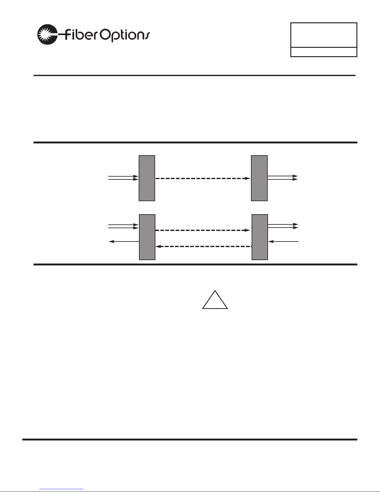
FIGURE 1: SYSTEM DIAGRAM 9900V & 9900VL MODELS
one single-mode
optical fiber
from two
to twenty
video inputs
from two
to twenty
video outputs
9900V-T
9900V-R
FIGURE 2: SYSTEM DIAGRAM 9900VD MODELS
one or two single-mode
optical fibers
from two to ten
video inputs
one
data ouput
from two to ten
video outputs
one
data input
9900VD-T
9900VD-R
www.fiberoptions.com
Fiber Options 80 Orville Drive, Bohemia, NY 11716
phone: 631.567.8320 or 800.342.3748 info@fiberoptions.com fax: 631.567.8322 or 877.342.3732
GENERAL
This manual is a guide to the installation and operation of
the 9900V series fiber optic digital video transmission
system and 9900VD series fiber optic digital video with
return data transmission system. Please read the entire
manual before installing the equipment.
Note: The series numbers 9900V-T and 9900V-R will be
used to describe all models of transmitters and receivers
unless noted otherwise.
The 9900V-T transmitter consists of a single 1-RU (rack
unit) module with from 2 to 10 video inputs and one fiber
output. The 9900V-R receiver unit has one fiber input
and from 2 to 10 video outputs.
The 9900VD-T transmitter has from 2 to 10 video inputs
with 1 data output connection and 1 or two fiber input/outputs. The 9900VD-R receiver has 1 or 2 fiber input/outputs, from 2 to 10 video outputs, and 1 data input.
Models with from 12 to 20 inputs (9912V to 9920V) consist of two 1-RU modules at each end, joined by an optical jumper.
LASER SAFETY
CAUTION: Class I Laser Product.
Invisible Radiation at Aperture.
Avoid Exposure to Beam.
Although this is a Class I laser product, which is not considered hazardous, keep in mind that the beam is invisible. For your further protection we suggest that you:
✹ Do not turn on any transmitter unit unless both ends
of the fiber are connected.
✹ Never look into the fiber optic connector on the back
of any unit when the unit is turned on.
✹ Never look directly at the end of the fiber optic cable
when the unit is turned on.
✹ Do not aim activated fiber optic cable ends at reflec-
tive surfaces or other persons.
. . . light years ahead
11-9900V-000918
!
www.fiberoptions.com
info@fiberoptions.com free phone: 800.342.3748 free fax: 877.342.3732
ELECTRICAL SAFETY
In order to protect the user from injury and the product
from damage please note the following.
Grounding
This product is intended to be electrically grounded and is
equipped with a three-wire grounding plug, which fits only
a grounded AC outlet. DO NOT DEFEAT THE PURPOSE
OF THIS GROUNDING PLUG.
INSTALLATION
Unpacking the Unit
In the event that anything is missing from the following list,
contact your authorized Fiber Options dealer or representative. Save the original packing materials in case it
becomes necessary to return the unit.
Remove all materials from the packing box and confirm
receipt of the following:
9900V-T Transmitter or 9900V-R Receiver
AC Power Cord
Model 648P Power Supply
2 Brackets for Rack or Wall Mounting
4 Screws for attaching Brackets to 9900V
4 Rubber Feet for Desk-top Mounting
Fiber Jumper (Models 9912V - 9920V ONLY)
Instruction manual
GENERAL INSTALLATION
Installation Considerations
You may select any one of three methods of installation,
depending upon the conditions and limitations of the site.
The 9900V series units may be installed in a standard 19-
inch rack, as a desktop unit, or as a wall-mounted unit.
In all cases, after selecting the method of installation and
the location, verify that there is enough space to pull and
connect all cables without stressing them beyond the
manufacturer's minimum bend radius limitation. Also consider future accessability issues when selecting the location. Refer to the included engineering drawings for front
and rear panel layouts.
Rack-mount Installation
Using the 4 screws provided, attach the rack-mount tabs
to the 9900V. Locate the vertically aligned mounting holes
on the left and right sides of the unit and position the
round screw-holes on the tabs over them. Be sure that the
oblong screw-holes on the tabs are facing forward and
that the tabs are flush with the front bezel of the unit.
Attach each tab with 2 screws. Do not over-tighten the
screws.
At this point, the 9900V is ready to mount in a standard 19
inch EIA rack, using appropriate screws. Fasten the
9900V to the rack securely, again being sure not to overtighten the screws. When installing more than one 9900V
in a rack or in a rack that is partially populated with other
equipment, be sure to provide adequate ventilation
between the units. A minimum of 1 RU (1.75 inches) is
recommended for air flow.
Desk-top Installation
Place the 9900V upside-down on a flat surface being
careful not to scratch the surface of the unit. Wipe the
bottom of the 9900V with a soft, dry cloth to remove any
dust or dirt. Remove the backing from the provided rubber
feet and attach them to the bottom of the 9900V, placing
them approximately 1 inch from each corner of the unit.
Press firmly to ensure a good bond. Turn the 9900V over
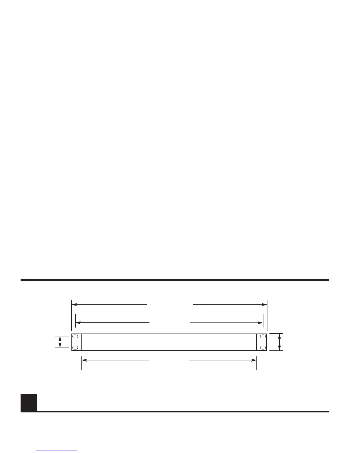
FIGURE 3: 9900V SERIES DIMENSIONS (ALL UNITS)
19.0 in (48.3 cm)
with mounting tabs
installed
18.25” (46.4 cm)
1.25 in
(3.2 cm)
1.72 in
(4.4 cm)
17.0 in (43. cm)
2
Note: Depth of all 9900V units = 11.7 inches (29.7 cm)
including panel-mounted BNC connectors.
and place it on the desk-top.
If more than one 9900V is to be installed, repeat the
above process. The 9900V units may be stacked one on
top of another, but should not be stacked higher than 4
units for stability.
Wall-mount Installation
Select the area on the wall where the 9900V will be
installed and determine where the power supply will be
located. Be sure that both an a/c power source and the
9900V will be within reach of the power supply. Also verify that there will be no excessive strain on the power connection at the 9900V. It is also recommended that the unit
be mounted in such a way that the LED indicators will all
be readily visible.
CAUTION: Do not attempt to attach the 9900V to a drywall surface.
Locate the mounting holes on the left and right sides of
the unit, 2 sets of 2 horizontally aligned holes on each
side. Position the round screw-holes on the tabs over the
mounting holes on the 9900V, being sure that the oblong
screw-holes are flush with the bottom of the unit. Attach
each tab securely to the 9900V with 2 screws, but do not
over-tighten the screws. Refer to Figure 4.
Mount the 9900V to the wall, using 4 screws suitable for
fastening to the selected surface. Use screws that are sufficiently long to provide secure mounting to the wall.
Power Connection
The 9900V series units are supplied with an external DC
power supply, model 648P. A permanently attached cable
is provided for the DC ouput and a detachable three-wire
grounded cable is provided for AC input.
CAUTION: Do not connect the unit to an AC power
source until directed to do so.
1. Remove the detachable screw terminal power connector from the back of the 9900V unit.
2. The external 648P power supply has a pendant cable
with two tinned leads. Connect these leads to
the power connector as shown in Figure 5.
3. Verify that the power supply is not connected to a wall
outlet, and insert the detached power connector into
its socket on the back of the 9900V unit.
See the Electrical Safety section on page 2 for additional
electrical connection information and safety precautions.
Do not plug the power supply into an AC outlet at this
time.
Fiber Optic Cable Connection
Most cable manufacturers identify the individual fibers in
the cable. Select appropriately terminated fiber and mark
both ends with unique identification label (e.g. for cable
no. 03, fiber no. 08) to ensure that the fiber connected to
the near end is the same one that is connected to the far
end.
The proper optical connection will link the transmitter's
OUT port to the receiver's IN port.
www.fiberoptions.com
info@fiberoptions.com free phone: 800.342.3748 free fax: 877.342.3732
3
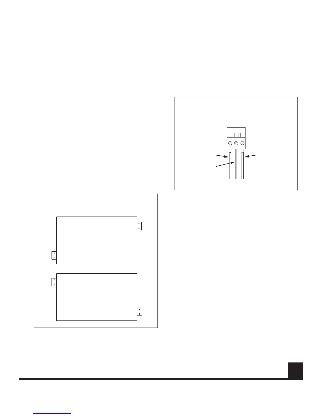
FIGURE 5: DETACHABLE SCREW TERMINAL
POWER CONNECTOR.
FIGURE 4: LOCATION OF BRACKETS FOR WALL
MOUNTING.
To Power Supply
Black (-) Red (+)
Chassis
Ground
Front
Rear
Rear
Front
or
continued on page 5
 Loading...