

fiberon SYMMETRY SIGNATURE Installation Instructions Manual
®
SYMMETRY
SIGNATURE
Low-Maintenance Composite Railing
6-ft. and 8-ft.
INSTALLATION INSTRUCTIONS
Manufactured by
berondecking.com
800.573.8841
Symmetry Signature Railing Installation Instructions - 6-ft. and 8-ft. Line
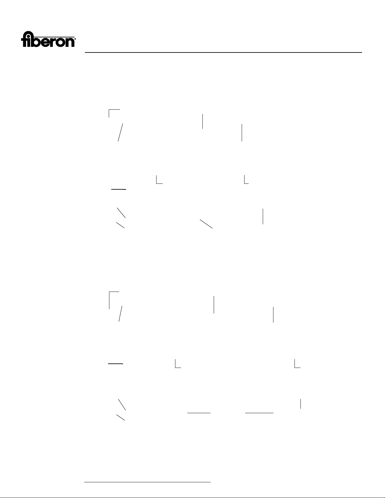
Railing component list for 6-ft. section:
Maximum length between post sleeves is 67 inches.
Post Sleeve Cap
• Top Rail
Top Rail Bracket
• Bottom Rail
• H-Channel
• Hardware and Screws
• 14 Balusters
Square
Composite
Balusters
• Crush Block
• Post Caps
Post
Sleeve
• Post Sleeves
• Post Skirt
Bottom Rail Bracket
Post Sleeve Base Moulding
Railing component list for 8-ft. section:
Post Sleeve Cap
Top Rail
Top Rail H-Channel
Round
Metal
Balusters
Crush Block
Bottom Rail
Maximum length between post sleeves is 91 inches.
Top Rail
• Top Rail
• Bottom Rail
• H-Channel
• Hardware and Screws
• 20 Balusters
• 2 Crush Block
• Post Caps
• Post Sleeves
• Post Skirt
1
Top Rail Bracket
Square
Composite
Balusters
Post
Sleeve
Bottom Rail Bracket
Post Sleeve Base Moulding
Note: Rail lengths will vary slightly due to manufacturing processes. Ensure rails are cut to
correct length with hole pattern centered between posts before securing.
The most recent installation instructions can be found on our website.
Please visit https://www.berondecking.com/resources/installation-instructions or call Consumer and Technical Support at 800-573-8841.
Crush Blocks
Top Rail H-Channel
Round
Metal
Balusters
Bottom Rail

Symmetry Signature Railing Installation Instructions - 6-ft. and 8-ft. Line
Required Tools and Supplies:
Top Rail Prole
• Power Drill
• Protective Eye Wear
• Pencil
• Adjustable Square
• Tape Measure
• Level
• Speed Square
• Miter Saw
Bottom Rail Prole
Prior to installing railing: Please consult local zoning laws regarding load requirements and bottom space requirements for rails. All supporting
structures must be in accordance with applicable building codes. Neighborhood associations and/or historic districts may regulate size,
placement, and type of railing. Apply for permits if required by local authorities and codes. Ensure compliance prior to installation. Local building
code requirements will always supersede any and all suggested procedures and measurements in the following instructions. The following
installation instructions are intended as a general guideline based on common building practices used in railing installation.
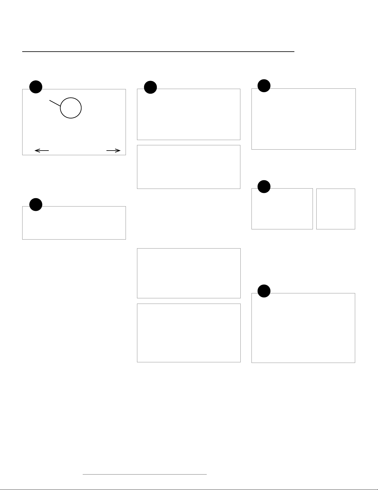
YES
NO
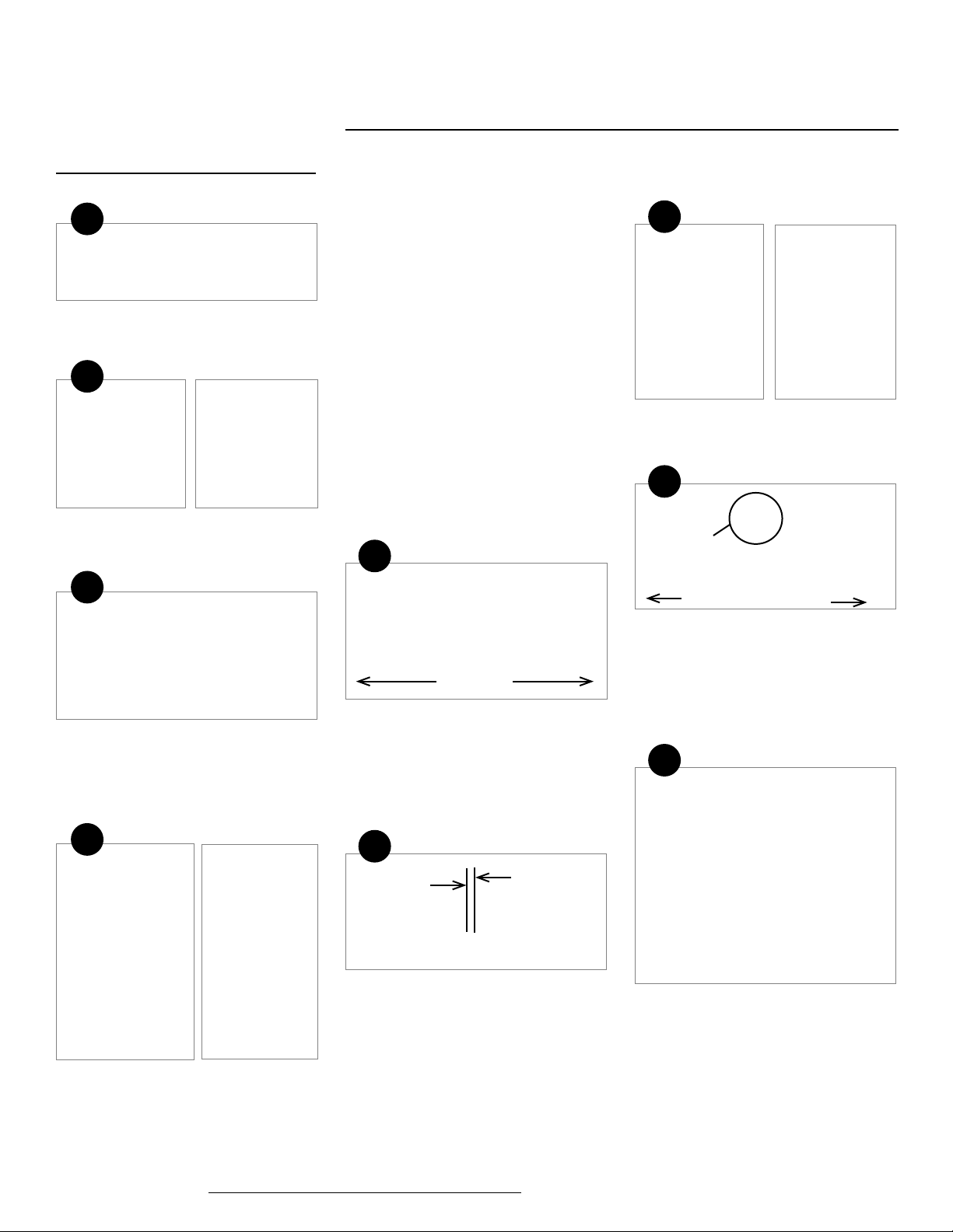
1-1/2-in. minimum from rail end to baluster
Rail Installation: When top and bottom rail length is greater than the distance between posts, trim both ends of the rail to maintain uniform
baluster spacing. It is critical to ensure the trim mark does not interfere with the balusters once installed.
1
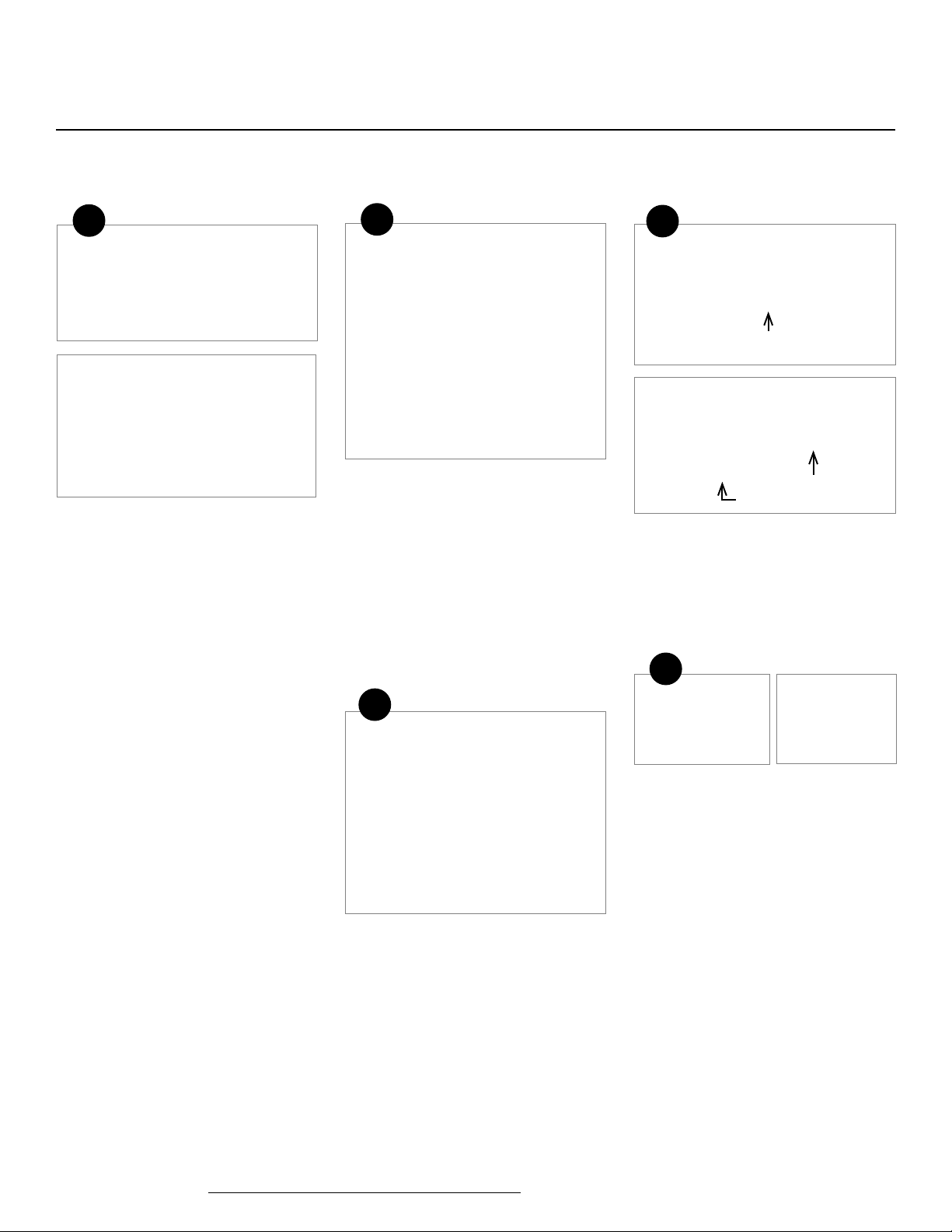
Note: Make sure posts are plumb and level
prior to installing the railing.
Cover 4x4 posts or Fiberon surface mount
bracket with post sleeve and verify spacing.
Posts should be plumb in both directions.
Place post sleeve base moulding over post
sleeve and slide it down to the deck surface.
Please visit https://www.berondecking.com/resources/installation-instructions or call Consumer and Technical Support at 800-573-8841.
2
Measure the distance between the posts
for the bottom rail. Center the hole pattern,
then mark the cutting points. Check for t.
Center the bottom rail with the top rail. Mark
and cut to length.
The most recent installation instructions can be found on our website.
3
7/32-in.
Align the H-bar and the cut bottom rail hole
patterns. Mark the length of the bottom rail
on the H-bar, then subtract 7/32-in. from that
measurement on each end of the H-bar (7/16in. total to allow for top bracket thickness) and
mark. Cut the H-bar and set aside for step 7.
2
Symmetry Signature Railing Installation Instructions - 6-ft. and 8-ft. Line
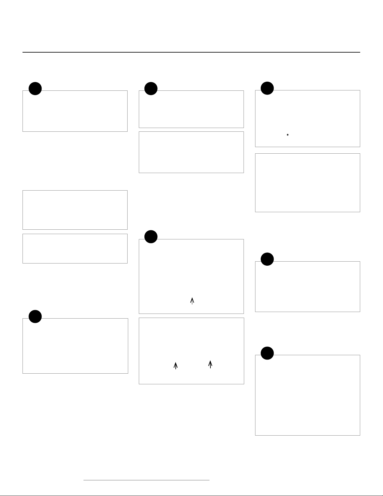
4
Aligning feature
Yard Side Deck Side
Ensure that the bottom rail is positioned
correctly prior to installation. The bottom rail
has an aligning feature on the top, which
should be on the yard side of the rail opposite
to the deck side.
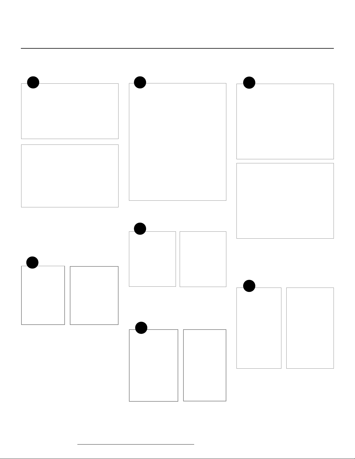
5
Square Composite Balusters: Measure and
trim all balusters to the required length.
Remove the baluster guide from the railing
box, place on a at surface, and insert the
balusters into the precut slots.
Note: Square composite baluster lengths
will very slightly due to manufacturing
processes. Insure balusters are cut to
uniform length.
Note: Round metal balusters do not
require trimming.
6
Square Composite Balusters: Align the bottom
rail with the balusters on the same end as the
baluster guide. Hold square balusters securely
against the aligning feature on the bottom rail
and secure the balusters to the bottom rail
with the supplied #10 x 1-1/2-in. screws. Do
not over-tighten
7
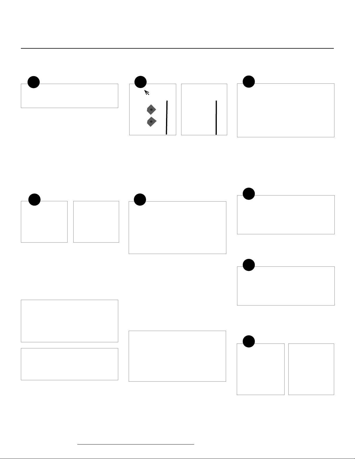
H-bar Bracket
Bottom Rail Bracket
Ensure that the brackets are positioned
correctly prior to installation. The brackets
indicate which side will be facing the decking.
8
Fully insert top brackets into both ends of
the aluminum H-bar with the arrow pointing
upward.
Using integrated screw template, secure with
self-drilling #10 x 5/8-in. screws. Do not overtighten.
9
Round Metal Balusters: Align baluster with
predrilled holes in bottom rail. Insert supplied
#10 x 1-1/2-in. screw through hole and
into the center (“X”) of the ns inside of the
baluster. Do not over-tighten.
Align the aluminum H-bar with the balusters
with the side holes facing upward.
Square Composite Balusters: Slide the baluster
guide to the opposite end of the balusters.
Insert the top of the balusters fully into the
channel of the aluminum H-bar rail.
Note: When securing composite or metal
balusters, shim the H-bar with a 1/2-in. –
5/8-in. spacer to help ensure balusters
remain perpendicular to the H-bar.
3
Please visit https://www.berondecking.com/resources/installation-instructions or call Consumer and Technical Support at 800-573-8841.
The most recent installation instructions can be found on our website.
Symmetry Signature Railing Installation Instructions - 6-ft. and 8-ft. Line
10
Square Composite Balusters: Position the top
of the balusters tightly against the inside of
the top H-bar. Center the balusters under the
side-mounting screw holes. Working from one
end to the other, secure each baluster using
the supplied #8 x 1-1/2-in. at head screws.
Do not over-tighten.
12
Dry t, measure, and trim crush block to the
required nal length. Secure crush block to
holder using supplied at head screw.
Note: When using the bracket template, a
3-3/4-in. tall crush block is required. The
screw will be off-center in the crush block.
13
14
Pre-drill the two holes with a 1/8-in. bit, taking
care not to drill through the top of the bottom
rail. Secure with the supplied at head screws.
Do not over-tighten.
15
Round Metal Balusters: Insert supplied #10 x
1-1/2-in. screw through holes in the H-bar,
and into the center (“X”) of the ns inside of
the baluster. Drive until secure. Do not overtighten.
11
Locate the Symmetry Signature bottom line
bracket template (included on the post sleeve
carton and inside the rail kit box).
Using the bottom bracket template, position
and secure bottom brackets using the
supplied #10 x 2 ½-in screws, ensuring the
bracket is positioned correctly (see step 7).
The template will create a 3-in. gap under the
bottom rail.
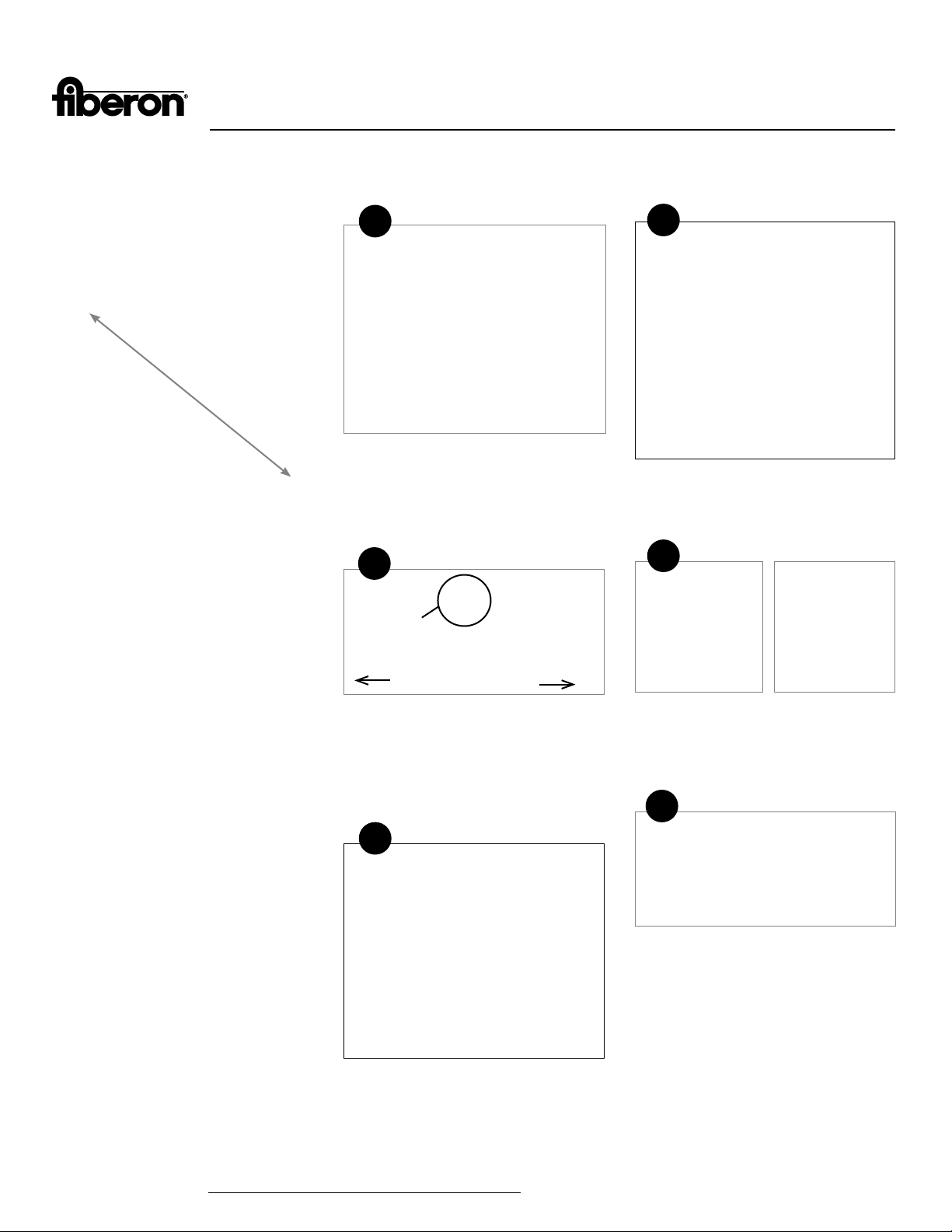
Approximate center on a rail section up to 6 ft.
Carefully position the pre-assembled railing
inll between the posts, then slowly lower over
the bottom brackets until fully seated.
16
Approximate 1/3 and 2/3 on a
rail section longer than 6 ft.
For 6-ft. rail sections, position the crush
block and holder inside the bottom rail at the
approximate center point.
For 8-ft. rail sections, position the two crush
blocks and holders inside the bottom rail at
the approximate 1/3 and 2/3 points.
Center the H-bar on the post and check rail
for plumb.
Please visit https://www.berondecking.com/resources/installation-instructions or call Consumer and Technical Support at 800-573-8841.
The most recent installation instructions can be found on our website.
4
Symmetry Signature Railing
Installation Instructions 6-ft. and 8-ft. Line (cont.)
Symmetry Signature Railing Installation Instructions - Angled Line
17
Secure the top brackets with the supplied
#10 x 2-1/2-in. screws.
18
Position the top rail over the inll assembly and
carefully lower into place.
19
Using supplied 1-1/2-in. screws, secure
the top rail starting as close to the post as
possible. Space the remaining screws evenly.
Note: Angled installations require a
minimum 5x5 post.
1
Deck Side Yard Side
For angled line installation, the line brackets
must be installed with the angled edge on
the deck side of the railing.
Note: This is opposite of what is indicated
on the line bracket for basic line railing
installation.
3
Secure with supplied #10 x 2-1/2-in. selfdrilling screws. Do not over-tighten.
4
Aligning feature
Yard Side Deck Side
Ensure that the bottom rail is positioned
correctly prior to cutting the bottom rail
angle for installation. The bottom rail has an
aligning feature on the top, which should be
on the yard side of the rail opposite to the
deck side.
5
20
Complete the assembly by gluing the post
caps in place with a quality exterior-grade
adhesive.
5
Please visit https://www.berondecking.com/resources/installation-instructions or call Consumer and Technical Support at 800-573-8841.
2
7/32-in. - 1/4-in.
The template can still be used to locate
the height of the line bracket. The side-toside alignment needs to be approximately
7/32-in. – 1/4-in. off-centered from the
deck side of the railing for a full 45-degree
installation.
Note: If the bracket is not offset slightly,
the top rail may overhang the corner post
face and extend into the corner chamfer.
The most recent installation instructions can be found on our website.
Center the hole pattern in the bottom rail
between the posts. Transfer length and
angle to the top rail and cut both top and
bottom rails. When aligning the hole pattern,
transferring length, and cutting angles on
the H-bar, remember to subtract 7/32-in.
from each end to allow for top brackets.
Symmetry Signature Railing Installation Instructions - Angled Line
6
Square Composite Balusters: Measure and
trim all balusters to the required length.
Remove the baluster guide from the railing
box. Place on a at surface and insert the
balusters into the precut slots.
Note: Square composite baluster lengths
will very slightly due to manufacturing
processes. Insure balusters are cut to
uniform length.
Note: Round metal balusters do not require
trimming.
7
Square Composite Balusters: Align the bottom
rail with the balusters on the same end as the
baluster guide. Hold square balusters securely
against the aligning feature on the bottom rail
and secure the balusters to the bottom rail
with the supplied #10 x 1-1/2-in. screws. Do
not over-tighten
8
NO YES
Insert top brackets into the cavity of the
aluminum H-bar, ensuring that the top bracket
is located within the boundaries of the H-bar.
If the bracket is outside of the boundaries, the
top rail will not t over the H-bar and bracket.
Secure with the supplied #10 x 5/8-in. selfdrilling screws.
9
Square Composite Balusters: Position the top
of the balusters tightly against the inside of
the top H-bar. Center the balusters under the
side-mounting screw holes. Working from one
end to the other, secure each baluster using
the supplied #8 x 1-1/2-in. at head screws.
Do not over-tighten.
Note: The screws should penetrate fully
through the baluster.
10
Assemble and attach the crush block
following standard line railing instructions.
Position the assembled inll over the bottom
brackets and carefully lower into place and
secure the top brackets with the supplied #10
x 2-1/2-in. screws.
11
Position the top rail over the inll assembly,
and carefully lower into place.
12
Using supplied 1-1/2-in. screws, secure
the top rail starting as close to the post as
possible. Space the remaining screws evenly.
Round Metal Balusters: Align baluster with
predrilled holes in bottom rail. Insert supplied
#10 x 1-1/2-in. screw through hole and
into the center (“X”) of the ns inside of the
baluster. Do not over-tighten.
The most recent installation instructions can be found on our website.
Please visit https://www.berondecking.com/resources/installation-instructions or call Consumer and Technical Support at 800-573-8841.
Round Metal Balusters: Insert supplied #10 x
1-1/2-in. screw through holes in the H-bar,
and into the center (“X”) of the ns inside of
the baluster. Drive until secure. Do not overtighten.
13
Complete the assembly by gluing the post
caps in place with a quality exterior-grade
adhesive.
6
Symmetry Signature Railing Installation Instructions - 6-ft. and 8-ft. Stair
The maximum length between
post sleeves measured in line with
the guardrail cannot exceed 5 in.
short of full length, depending on
which kit is being used.
1
Cover 4x4 posts or Fiberon surface mount
bracket with post sleeve and verify spacing.
Posts should be plumb in both directions.
Place post sleeve base moulding over post
sleeve and slide it down to the deck surface.
2
Aligning feature
4
Center the hole pattern between the posts,
allowing a minimum 1-5/8-in. from rail end to
routed baluster holes.
5
Building codes are very specic on
allowable angles and widths. It is very
important to consult with your local building
code ofcials and plan your stair layout
accordingly. Leave adequate space for
graspable hand rail if applicable.
Note: The slope of the stairs can be 30-37
degrees.
Note: Rail lengths will vary slightly due to
manufacturing processes. Make sure rails
are cut to correct length.
Yard Side Deck Side
Ensure that the bottom rail is positioned
correctly prior to cutting the bottom rail
angle for installation. The bottom rail has an
aligning feature on the top, which should be
on the yard side of the rail opposite to the
deck side.
3
To establish the stair angle, use a 1x4 or
similar support to bridge at least three stairs.
Place the bottom rail between the stair posts.
Transfer the stair angle to both ends of the
bottom rail and cut to the required length
and angle. Test for a snug t and make
corrections as needed.
6
Square Composite Balusters: Transfer the stair
angle to the balusters, and cut the balusters
to desired length.
Note: Round metal balusters are pre-cut on
one end. If a custom angle is required, cut
the factory angled end, leaving the square
end as is. This will allow proper seating
when securing the top of the balusters later
in the installation.
7
Please visit https://www.berondecking.com/resources/installation-instructions or call Consumer and Technical Support at 800-573-8841.
The most recent installation instructions can be found on our website.
Symmetry Signature Railing Installation Instructions - 6-ft. and 8-ft. Stair
7
To cut the H-bar, rst place the H-bar on
its side with the holes nearest to the cut
bottom rail. The bottom rail should be top
side up. Align the hole pattern with the cut
bottom rail.
8
10
The total length of the H-bar will be 7/16-in.
shorter than the cut bottom rail.
Scribe a second line 7/32-in. inside the rst
at both ends.
Note: This allows for the thickness of the
upper bracket.
11
13
Square Composite Balusters: Remove the
baluster guide from the rail box. Place on a
at surface and insert the balusters into the
precut slots.
Round Metal Balusters: Place cut bottom rail
on a at level surface. Align the cut-end of
the round metal baluster with the top surface
of the bottom rail.
14
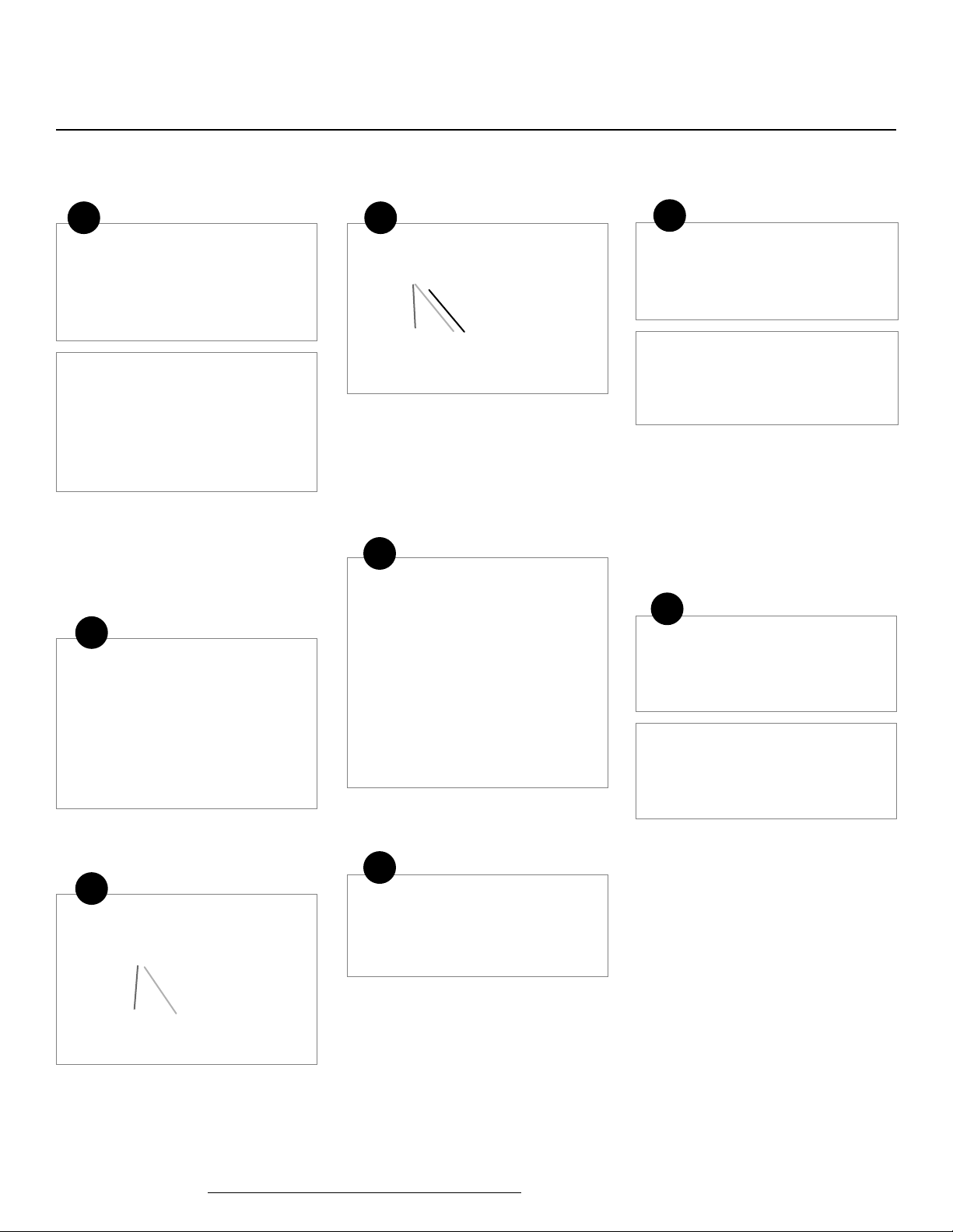
Transfer the length of the cut bottom rail to
the H-bar.
9
Scribe the stair angle to the side of the
H-bar at both ends.
Please visit https://www.berondecking.com/resources/installation-instructions or call Consumer and Technical Support at 800-573-8841.
Position the top brackets into the H-bar,
ensuring that they are inserted completely.
12
Secure the top brackets to the H-bar using
(two) 5/8-in. self-drilling pan head screws. Do
not over-tighten.
The most recent installation instructions can be found on our website.
Square Composite Balusters: Align the end
baluster with the predrilled hole in the bottom
rail. Secure the balusters using the supplied
#10 x 1-1/2-in. screws.
Hold each square composite baluster
securely against the aligning feature and
drive screws parallel with the balusters, not
perpendicular to the bottom rail. Do not overtighten.
Round Metal Balusters: Insert the screw into
the center “X” of the end baluster. It may be
necessary to slightly over-drill the factorydrilled holes by rocking the moving bit parallel
with the direction of the rail. Do not overtighten.
Continue working from one end until all the
balusters are secured into the bottom rail.
8
Symmetry Signature Railing Installation Instructions - 6-ft. and 8-ft. Stair
15
Note: It is important to ensure balusters
are level when securing. Shim the H-bar
with a 1/2-in. - 5/8-in. spacer to ensure
the balusters remain fully inserted when
securing.
Square Composite Balusters: Move the
baluster guide to the top rail end of the square
composite balusters.
Position the top of the balusters tightly
against the inside of the top H-bar. Center
the balusters under the side-mounting screw
holes. Working from one end to the other,
secure each baluster using the supplied
#8 x 1-1/2-in. at head screws. Do not overtighten.
Note: The screws should penetrate fully
through the baluster.
Secure the remaining balusters working to the
other end. Do not over-tighten.
Round Metal Balusters: Insert the round
baluster holders into the aluminum H-bar,
ensuring that the angled hole is oriented
correctly and that the through hole aligns with
the side holes in the H-bar.
Fully seat all balusters into the holders. Secure
an end baluster rst, using the supplied #8 x
1-1/2-in. at head self-drilling screws through
the H-bar side holes.
Pivot the H-bar toward the remaining
balusters, inserting them into the holders.
Start from the secured end and work
to the other end. Secure the remaining
end baluster, and then the remaining inll
balusters.
16
Dry t the assembled section and use the
bottom rail to scribe a light line on the post
to determine the location of the bottom rail
bracket.
Note: For best results, predrill bracket holes
on post with a 1/8-in. - 5/32-in. bit to ensure
accurate screw placement and full insertion,
particularly as the stair angle increases.
Secure the bottom stair brackets to the post
using the supplied #10 x 2-1/2-in. at the
desired height. Do not over-tighten.
17
Before assembling the crush block, transfer
the stair angle to the end of the crush block,
dry t, and cut to t.
18
Approximate center on a rail
section up to 6 ft.
Approximate 1/3 and 2/3 on a
rail section longer than 6 ft.
For 6-ft. rails sections, position the crush
block and holder inside the bottom rail at the
approximate center point.
For 8-ft. rail sections, position the two crush
blocks and holders inside the bottom rail at
the approximate 1/3 and 2/3 points.
19
Secure crush block to crush block holder
using a supplied #8 at head screw. Do not
over-tighten.
Note: The screw will be off-center in the
crush block.
9
Please visit https://www.berondecking.com/resources/installation-instructions or call Consumer and Technical Support at 800-573-8841.
The most recent installation instructions can be found on our website.
Symmetry Signature Railing Installation Instructions - 6-ft. and 8-ft. Stair
20
Position the crush block and holder into the
bottom rail, and locate the two screw holes.
Remove the holder and pre-drill using a
1/8-in. drill bit. Reposition the crush block and
holder, and secure with the supplied #8 x 1-in.
screws. Do not over-tighten.
21
22
Center the H-bar on the post and check rail
for plumb.
23
25
Using supplied 1-1/2-in. screws, secure
the top rail starting as close to the post as
possible. Space the remaining screws evenly.
Carefully position the pre-assembled railing inll between the posts, then slowly lower over
the bottom brackets until fully seated.
Please visit https://www.berondecking.com/resources/installation-instructions or call Consumer and Technical Support at 800-573-8841.
26
Starting at the top, secure the H-bar to
the posts at both ends using the supplied
#10 x 2-1/2-in. self-drilling pan head screws.
Do not over-tighten.
24
Complete the assembly by gluing the post
caps in place with a quality exterior-grade
adhesive.
Position the top rail over the inll assembly,
and carefully lower into place.
The most recent installation instructions can be found on our website.
10
 Loading...