

Page 1
Version 1.00
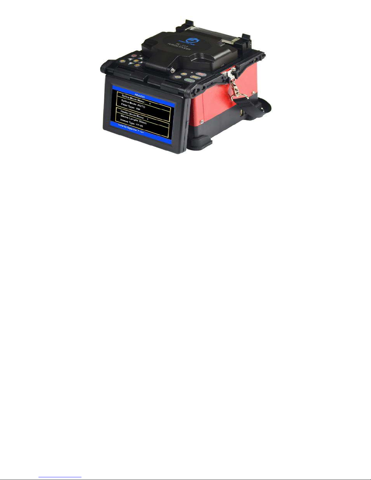
FL-117
Optical Fiber Fusion Splicer
User Manual
Price . 1,58,000/-
Page 2

Warning: Ignore the warning, non-proper use of fusion splicer could lead to fatal
and serious injur
y.
1. The input voltage of this model of machine is definite; please do not use the voltage
outside the scope. Please use the correct AC and DC power supply.
2. When the fusion splicer comes across the following failures, please immediately
remove the AC power cord from the power supply input and turn off the fusion
splicer, otherwise will lead to the incapable of the repairing and even will cause
personal injury, death and fire.
Smoke, smell, noise or heat anomaly
Broken or damaged machines
Liquid or foreign matter enters the interior of the machine
3. This model of fusion splicer does not have the need to maintain internal
components, dismantling of fusion splicer and power modules is prohibited; any
mistake in maintenance will lead to the machine beyond repair even causing bodily
harm.
4. The machine has strictly limitation to the power supply module used.
5. The fusion splicer is prohibited to be used under the environment with the
inflammable liquid or flammable gas; otherwise will lead to fire, explosion and
other serious consequences.
Disclaimer Clause
The Company does not assume any liability for all damage caused by the use
of non original battery.
To avoid possible wrong operation or insecurity, a valid ground three-hole
socket must be used when AC/DC adaptor access to AC 220V 50HZ power.
Page 3

Content
1. Brief Introduction ........................................................................................................ 1
1.1 Specifications .......................................................................................................... 1
1.2 Configuration of fusion splicer ................................................................................ 2
1.3 Parts Name of fusion splicer .................................................................................... 3
1. 4 Descriptions of the Keyboard .................................................................................. 4
2. Basic operation ............................................................................................................ 5
21 Descriptions of the power modules ....................................................................... 5
22 AC operation...................................................................................................... 5
23 Battery supply operation .................................................................................... 6
2.4 Turn on and turn off ................................................................................................. 9
2.5 Display brightness control ....................................................................................... 9
2.6 Cover fiber protection sleeve .............................................................................. 10
2.7 Preparation of fiber end-face .................................................................................. 10
2.8 Place fiber ................................................................ .............................................. 12
3
Check and Maintenance .......................................................................................... 13
3.1 Cleaning V-grooves ............................................................................................... 13
3.2 Cleaning Fiber Clamp Chips .................................................................................. 14
3.3 Cleaning Wind Protector Mirrors ........................................................................... 14
3.4 Cleaning Objective Lenses..................................................................................... 15
3.5 Replace Electrodes................................................................................................. 15
3.6 Set Calendar .......................................................................................................... 17
4. Change the spare lithium battery pack ...................................................................... 17
5
.
Power Supply ............................................................................................................. 18
Addenda A: Summary of quick operating ..................................................................... 20
Addenda B: Guarantee period and limits ...................................................................... 22
Addenda C: Contact ....................................................................................................... 23
Page 4

1
1. Brief Introduction
Nanjing Fiberlink Communication Technology Co., Ltd. is a company specializing in the
production of optical fiber fusion splicer, optical fiber cleaver, OTDR, light source, optical
power meter, and optical fiber fixture, and other optical communication instrument high-tech
enterprises. Company production of FL-117, FL-118, F series fiber splicing machine is not
only widely used in China Telecom, China Mobile, Unicom, radio and television major
domestic telecommunications operators, but also exported to South America, Europe, Russia,
Southeast Asia and Africa and other parts of the world.
1.1 Specifications
Model FL-117 FTTH Fusion Splicer
Splicing Type SM, MM, DS, NZDS
Splicing Loss 0.02dB(SM)0.01dB(MM)0.04dB(DS)
Return Loss >60dB
Splicing Mode Manual, Half Auto, Auto
Fiber Alignment Core to Core Alignment by PAS technology
Applicable Fiber Cable indoor and 0.25mm,0.9mm fiber, SC
connector(option)
Splicing Time ≤9s
Heat Time ≤30s
Cleaved Length 816mm
Fiber Image/ Magnification 300/200 times
View Display 5 inch digital high-quality LCD screen
Tension Test Standard 2N (option)
Heat Shrinkable Sleeve 60mm, 40mm and serials heat Shrinkable Sleeve
Battery Capacity 200 cycles splicing and heating, 3 hours charging time
( splicing and charging at same time)
Battery Life Cycling charge 300-500 times, easy to replace battery
Electrodes Life 3000, easy to replace electrodes
Power Source ≤20W
Interface USB Convenient data download and software update
Construction Lighting Built in high brightness, wide range of lights, easy to
operate at night
Power supply Built in lithium battery 5200mAh 11.1V; external
adapter, input: AC100-240V, output: DC13.5V/4.5A
Operating Condition 0-5000m above sea level, Temperature: -10-60,
Humidity:095%RH (No dew)
Weight (including battery) 1.98 KG (including battery)
Dimension (LxWxH) 135mm(L)×158mm(W)×155mm(H)
Page 5

2
1.2 Configuration of fusion splicer
Following is the standard configurations of fusion splicer:
No. Name Quantity
1 Fusion Splicer 1 set
2 Carrying Case 1 set
3 AC Adaptor 1 pc
4 Power cord 1 pc
5 Cooling tray 1 pc
6 Spare Electrodes 1 pair
7 User Manual CD 1 pc
8 Test Report 1 pc
Page 6
3
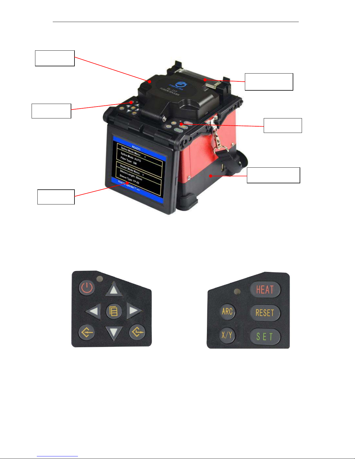
1.3 Parts Name of fusion splicer
Left Keyboard Right Keyboard
Power Module
Key board
Power switch
Windshield
Heater
LCD
Page 7
4
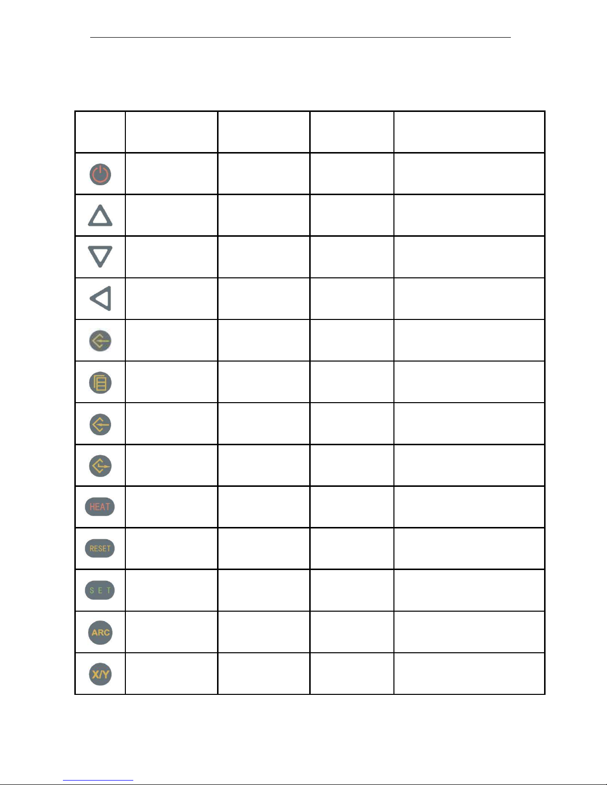
1. 4 Descriptions of the Keyboard
Membrane figure of left and right keyboards
Keyboard
Standby mode
Mode of manual
operation
Mode of automatic
operation
Mode of parameter menu
Power switch Power switch Power switch Power switch
To increase the
brightness of the display
The optical fiber moves
upward
Invalid
Increase the parameter quantum or
move the cursor
To reduce the brightness
of the display
The optical fiber moves
downward
Invalid
Increase the parameter quantum or
move the cursor
Invalid
The optical fiber moves
left
Invalid
Increase the parameter quantum or
move the cursor
Turn on the help screen
The optical fiber moves
right
Invalid
Increase the parameter quantum or
move the cursor
To enter the menu
mode
To switch on the manual
driver at pausing state
Invalid
Selectedit the fusion(heating)
parameter files
To enter “select splice
parameter files” menu
To enter the “select
parameter files” menu
Invalid
To enter the next menu interface/
confirm the modifier
Invalid Invalid Invalid Exit from the current menu screen
Heater switch Heater switch Heater switch Heater switch
Reset of motor Reset of motor Reset of motor Invalid
Start to fusion
Further propulsion/start
fusion
Invalid Invalid
Discharging Discharging Invalid Invalid
Switch X/Y display
screen
Switch X/Y display
screen
Switch X/Y display
screen
Invalid
Page 8
5
2. Basic operation
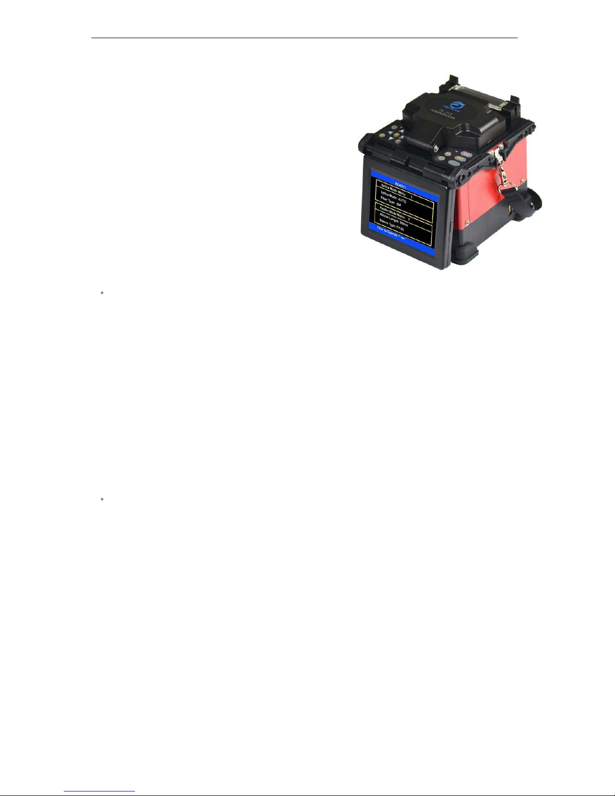
FL-117 Fusion splicer is designed to splice
many types of fiber by using core
diameter aiming rationale, its shape is
compact, light weight, which is suitable for
field work. Operation is simple, fusion speed
is high, and fusion loss is small.
2
1 Descriptions of the power modules
FL-117 Fusion Splicer uses 2 in 1 power module design, during the work,
the Fusion Splicer can be supplied by the polymer lithium ion battery
separately; or use AC adapter for electricity supply; when adapter is used for
electricity supply, the polymer lithium ion battery is charged at the same time.
The lithium battery to be changed must be the model specified by the
Company.
2
2 AC operation
2.2.1 When AC power supply is adopted, the AC/DC adapter supplied by the
company should be used. The basic parameters of the adapter are as
follows: INPUT: AC100-240V1.8A 50/60HZ
OUTPUT: DC13.5V ∕ 5A
2.2.2 The AC/DC adapter will not be able to supple normal DC output if the
input AC voltage is lower than 100V or higher than 240V. At this
situation, the DC output line of the adapter must not be inserted into
“POWER INPUT “specified on the power module of the Fusion
Page 9
6
Splicer, otherwise it will results in the damage of fusion splicer.
2.2.3 If lithium battery is arranged in the battery case, the battery pack will
also be charged when the adapter is supplying power. However, it is
recommended that the Fusion Splicer be shut when charged.
2
3 Battery supply operation
The user may choose to use the polymer lithium battery in the splicer to
separately supply for the Fusion Splicer.
2.3.1 Checking of battery capacity
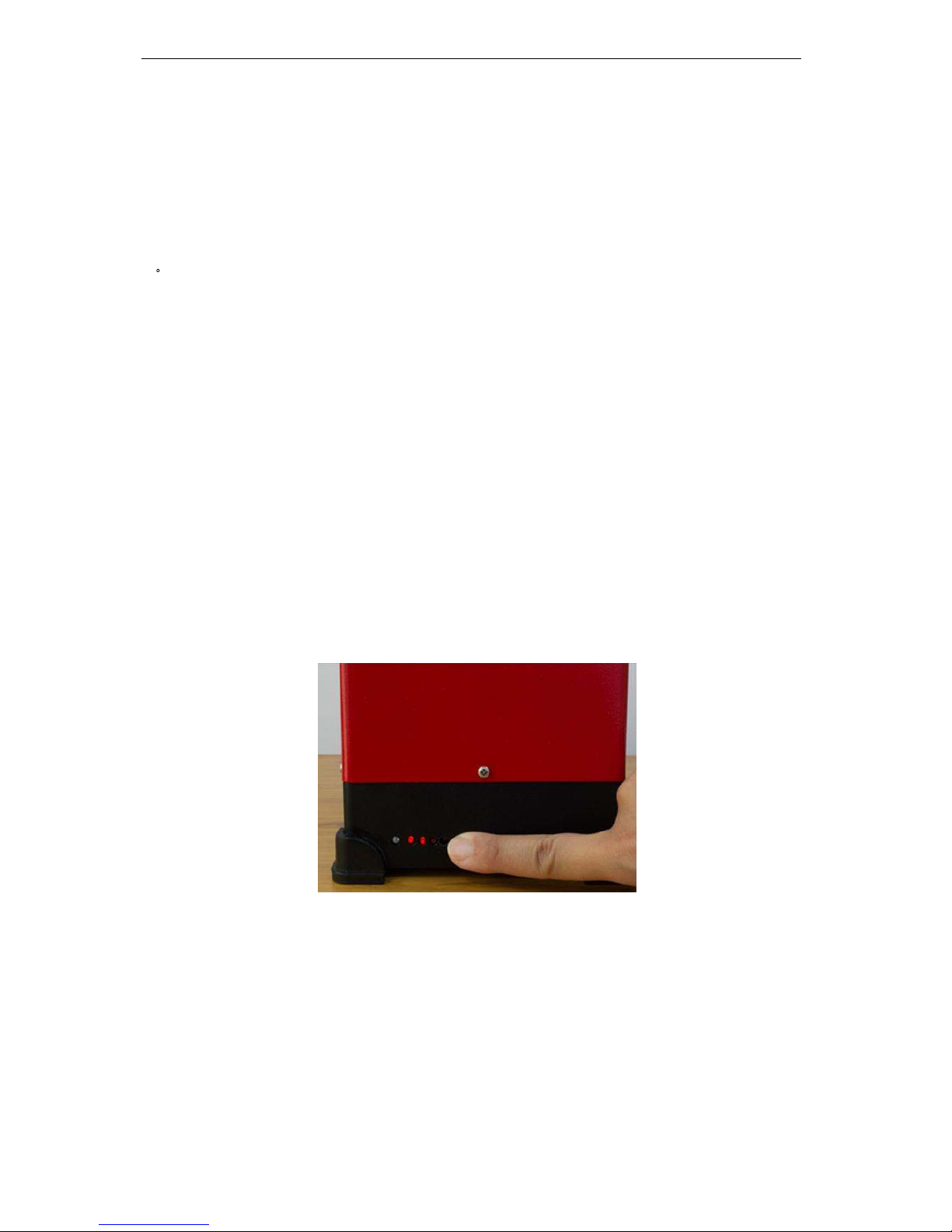
When the power module is not in the charged state, press the "PUSH"
button on the flank of the power module. Then the four battery capacity
indicator (red) lights on the left side will be bright. The number of the lit
light represents the highness or lowness of the battery capacity. See the
following table.
When the power module is in the charged state, the four battery
capacity indicator (red) lights on the left side will be bright, which only
represents the highness of the current charge voltage, but the capacity of
the battery.
Page 10

7
2.3.2 Battery charging
<1> Whether the battery capacity is in adequacy, every time the AC power
adapter is inserted into “POWER INPUT “on the Fusion Splicer power
module, the power module will start a charging process.
<2> Display of charged state: During the charging, the charging indicator
(CHARGE) light is red; after the charging completion, the charging
indicator (CHARGE) will be green.
<3> When the splicer is shut down, the maximum charging time is three
hours 40 minutes, and the shortest is 40 minutes. The length of the
charging time is dependent on the current battery capacity of the splicer.
<4> If the splicer is charged when it is active, the charging time should be
longer. The user is recommended to charge the battery when the splicer
is shut down, thus the charging time will be shortened.
2.3.3 Under Voltage Alarm
This model of fusion splicer has the function of “Under Voltage Alarm”.
If the capacity of the lithium battery is lower than the specified value (the
default value is around 10.3V), the splicer will automatically alarm and
lock the keyboard to disable input. The user should press
until the
Fusion Splicer is shut down, and charge the lithium battery pack as soon as
possible, or use the adapter to supply power.
Page 11

8
2.3.4 The other considerations
<1> For any fusion splicer not to be used for more than 1 month, it is
suggested to separate the lithium battery and machine for saving.
<2> The lithium battery should be charged in the environmental
temperature ranging between 040.
<3> The battery, with certain service life, belongs to consumables. When
the fusion splicer can only work for a short time despite the battery
level of the lithium battery above 90%, please replace the battery.
Please use the battery of the model designated by the Company for
replacement.
<4> Before the battery power supply for the fusion splicer, the battery
level must be checked. If the battery is low or the low voltage
warning is given, please recharge the lithium battery timely.
<5> Please do not charge or discharge the battery in a low temperature for
a long time to prevent the decrease of the battery life. Accidents may
happen if charging or discharging the battery or special battery charger
and battery in a high temperature.
<6>When charging the battery with the special battery charger,
immediately disconnect the charger when the battery is fully charged.
Huge damage may be incurred or accidents may occur on the lithium
battery if the battery fully charged is still under the charging state.
<7> The battery should be stored in a clean, dry and ventilated indoor
environment of temperature ranging –535 and humidity of
Page 12
9
65±20RH.
<8> If the battery is stored for a long time, it should be charged with the
special charger provided by the Company once every 90 days. The life
of the battery may be extended if the battery is half fully charged in a
long time.
<9> It is prohibited to remove the battery without explicit approval or put
it into fire, to prevent explosion of battery.
2.4 Turn on and turn off
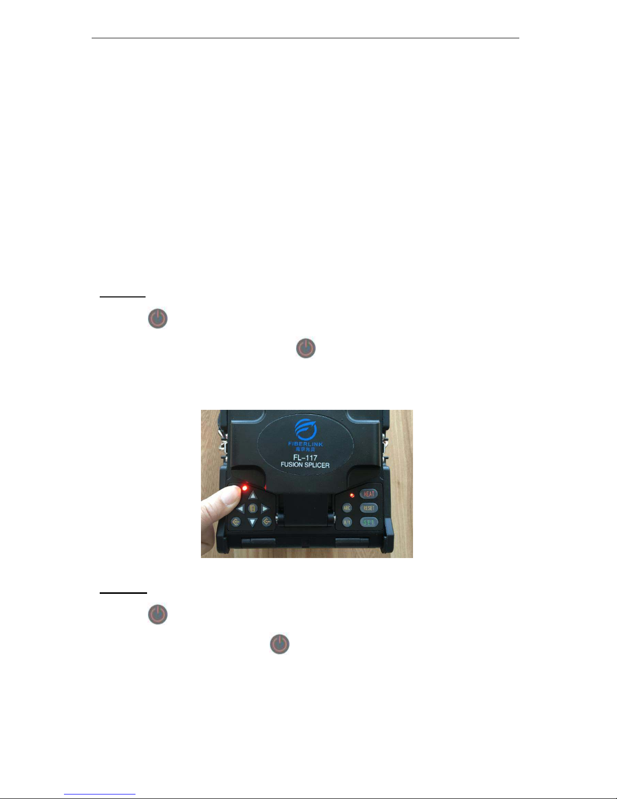
Turn on
Press button on the operator panel until the LED indicator lights turn
from green to red, release the button
. When all of the motors return to the
initial position, the screen shows the reset menu.
Turn off
Press button on the operator panel until the LED indicator turn from
red to green, release the button
, now the machine is turned off.
2.5 Display brightness control
When the external environment is different, the user can adjust the display
Page 13
10
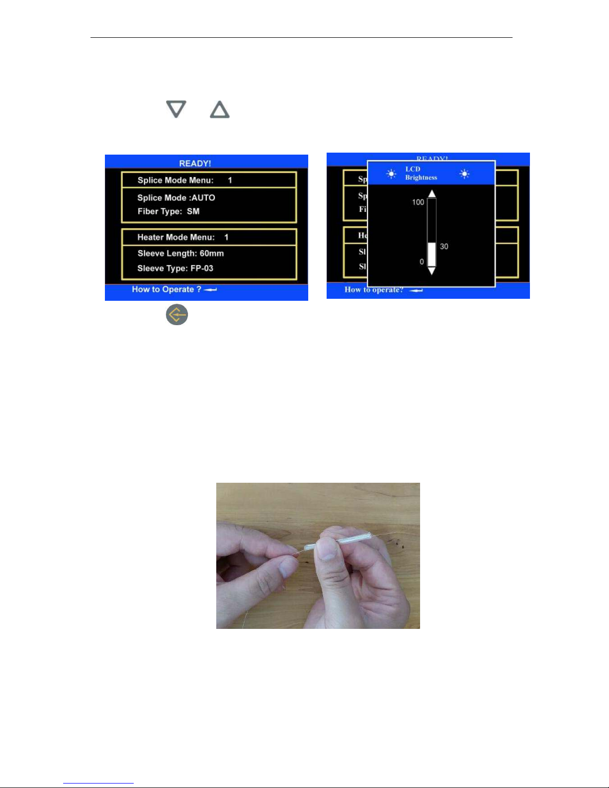
brightness for the convenience of the Fusion Splicer operation. Display
brightness control should be done in the “standby” operation interface.
<1> Press or in the “standby” operation interface to change the
brightness of the display.
<2> Press
to confirm the brightness changes, and return to “standby”
operation interface.
When the display brightness is moderate, the capacity loss can be
reduced, and the endurance of the battery can be prolonged.
2.6 Cover fiber protection sleeve
The installation of fiber protection sleeve
2.7 Preparation of fiber end-face
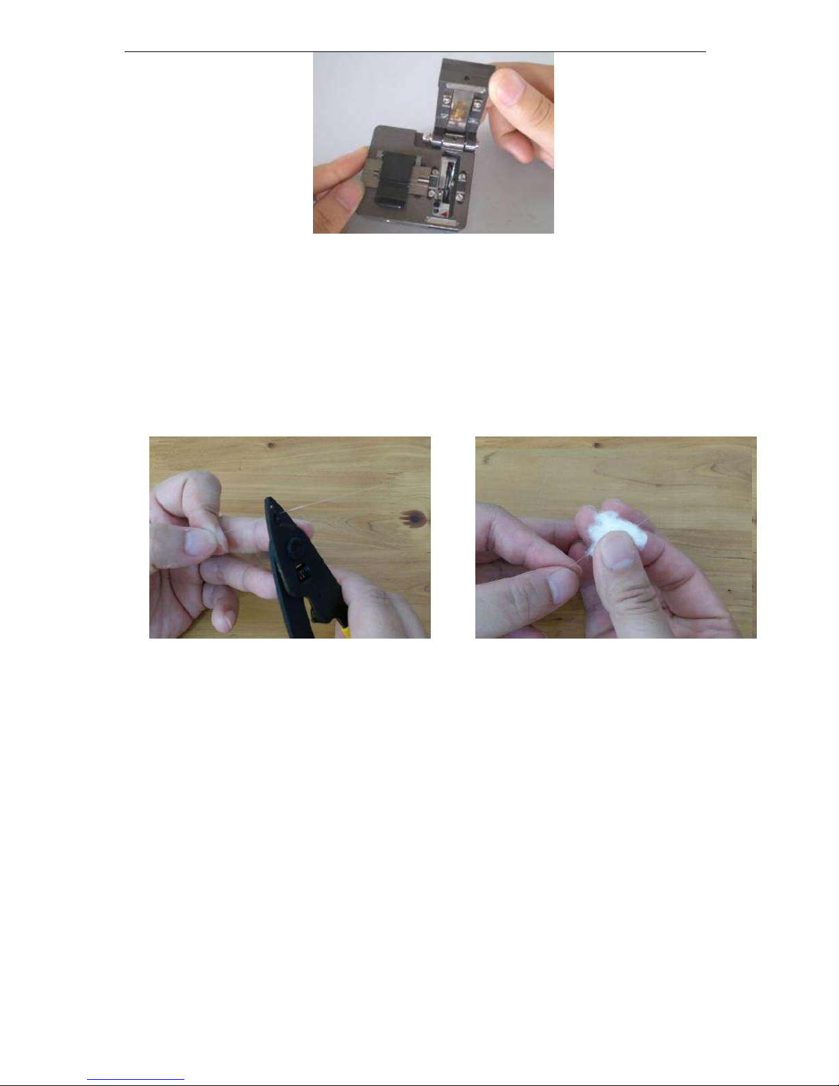
2.7.1 Open the big and small clips of the cutter; push the sliding plate
installed with blade from the end to the front.
Page 14
11
2.7.2 Use fiber stripping pliers to strip fiber coating layer, the length of
which is 30-40 mm. Use gauze dipping with alcohol or wadding soft
enough to wipe clean the fiber. Wiping with a clean cotton cloth once,
and do not clean it with the same cloth for the second time. (Notes:
Please use the alcohol with purity more than 99 %.)
Fiber stripping Clean
2.7.3 Aim the edge of the fiber coating layer at the “16”calibration of the
cutter yardstick and put the fiber into orientation pressure tank with
the left hand, and be sure that the bare fiber has been straightly put on
the right and left rubber pads.
2.7.4 Close the small clip, big clip by right hand and promote sliding plate
installed with blade to the other side, and then cut the fiber.
Page 15
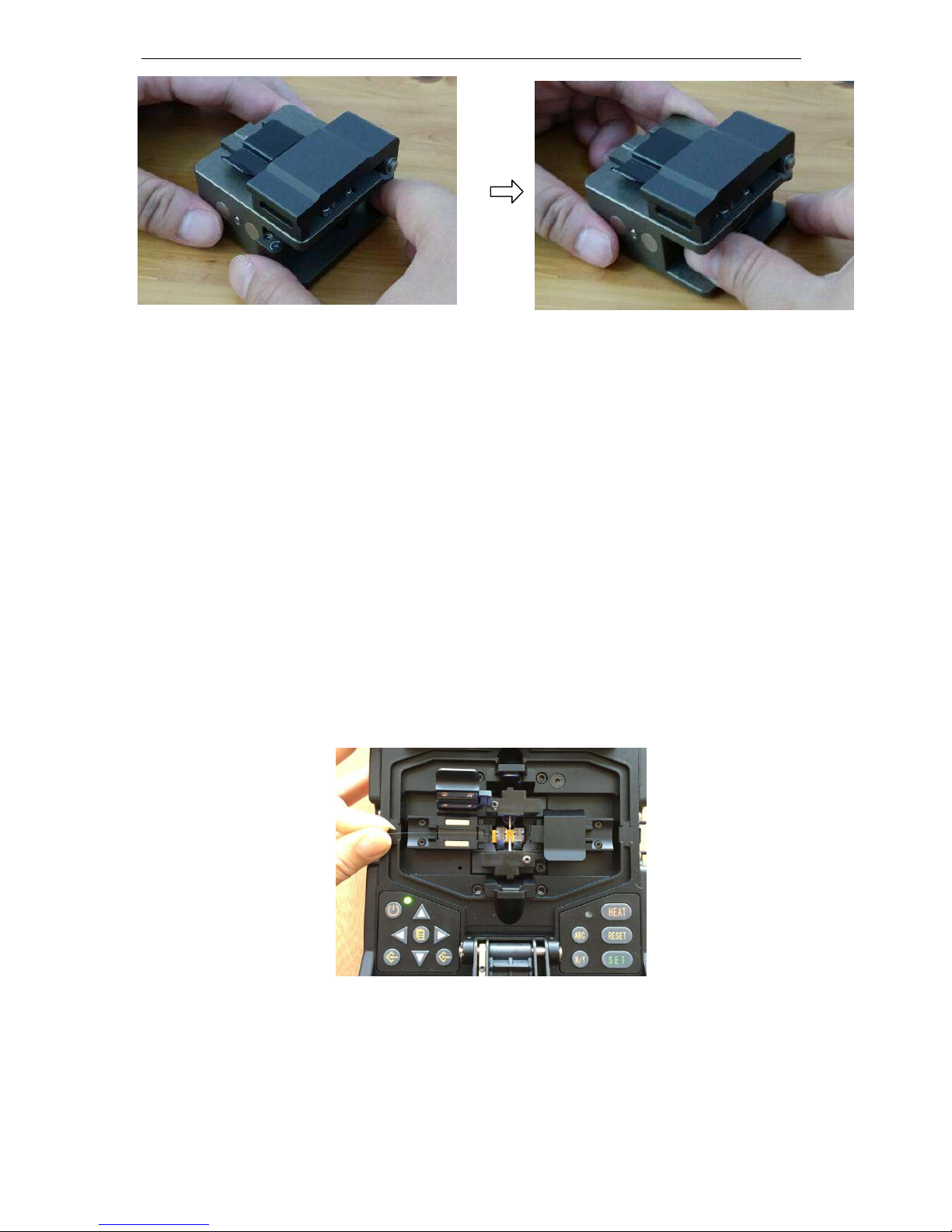
12
2.7.5 Hold the cutter by left hand and open the big clip by right hand and
remove the fiber chips to put them in fixed containers.
2.7.6 Pinch and hold the fiber with the left hand, and open the small clip
with the right hand at the same time, and carefully remove the fiber.
Notes: The clean cross-section of fiber cannot touch other things.
2.8 Place fiber
2.8.1 Open shielding cover and left and right fiber clips.
2.8.2 Put the good fiber end face in the V-shaped groove; ensure the tip of
the fiber between the tip of the electrode and V-shaped groove’s edge.
If the fiber is bending, bending part should be upward when placing
the fiber.
To ensure the splice quality of the fiber, the clean cross-section of fiber
cannot touch other things.
Page 16
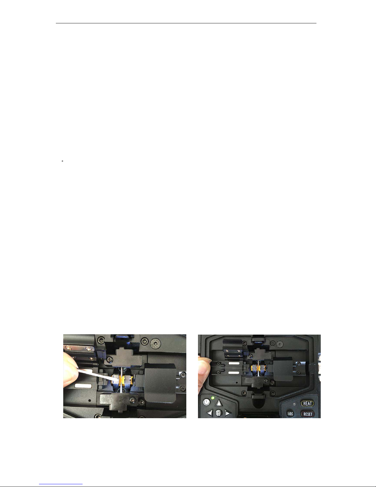
13
2.8.3 Use fingers to pinch the fiber, and then close the left clip, and press
the fiber. Ensure the fiber is placed in the bottom of V-shape groovy.
If the fiber is placed incorrect, please replace the fiber. The fiber end
face don’t touch the V-shape groove when place the fiber.
2.8.4 Place another optical fiber according to the above steps.
2.8.5 Close shielding cover.
3
Check and Maintenance
Critical cleaning points and maintenance checks are described below.
3.1 Cleaning V-grooves
If contaminants are present in the V-grooves, proper clamping may not
occur, resulting in higher splice loss. The V-grooves should be frequently
inspected and periodically cleaned during normal operation. To clean the
V-grooves do the following:
<1> Open the wind protector.
<2> Clean the bottom of the V-groove With an alcohol-impregnated thin cotton
swab. Remove excess alcohol from the V-groove with a clean dry swab.
Be careful to not contact the electrode tips.
Do not use excessive force when cleaning the V-groove.
Page 17
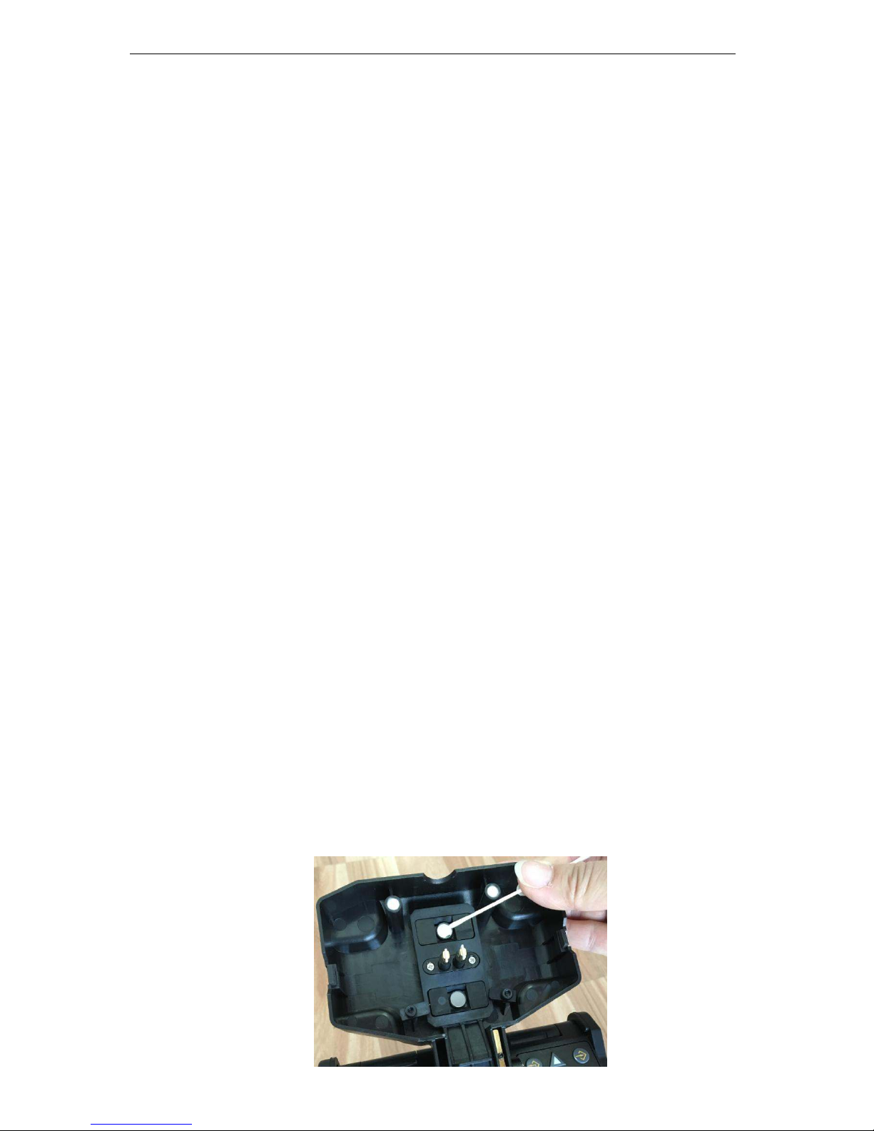
14
The V-groove arm may get damaged.
If the contaminants in the V-groove cannot be removed with an
alcohol-impregnated thin cotton swab, use a cleaved fiber end-face to
dislodge contaminants from the bottom of the V-groove. Repeat step 2 after
this procedure.
3.2 Cleaning Fiber Clamp Chips
<1> If contaminants are present on the clamp chips, proper clamping may not
occur, resulting in poor quality splices. The fiber clamp chips should be
frequently inspected and periodically cleaned during normal operation.
<2> To clean the clamp chips, do the following: Open the wind protector. Clean
the surface of the chip clamp with an alcohol-impregnated thin cotton
swab. Remove excess alcohol from the chip clamp with a clean dry
swab.
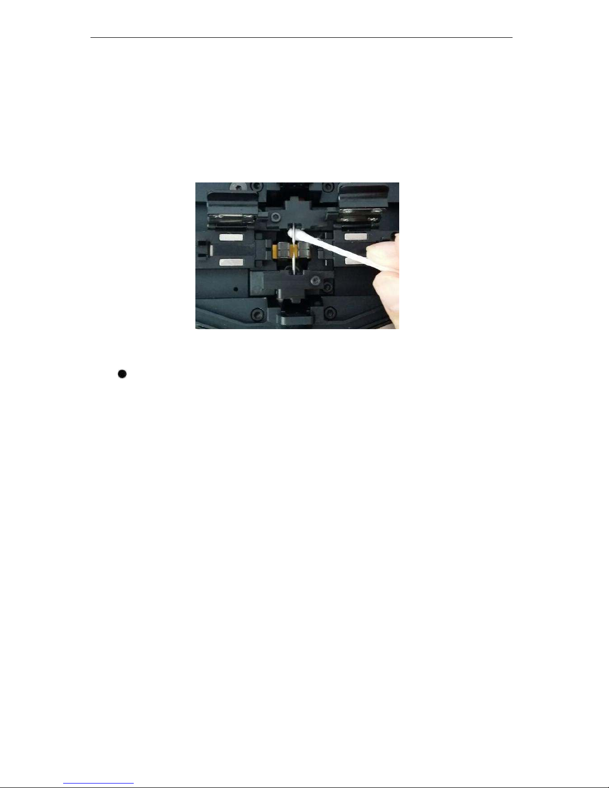
3.3 Cleaning Wind Protector Mirrors
If the wind protector mirrors become dirty, the fiber core position may be
incorrect due to decreased optical path clarity, resulting in higher splice loss.
To clean the mirrors, do the following: Clean the mirror surface with an
alcohol-impregnated thin cotton swab. Remove excess alcohol from the
mirror surface with a clean dry swab. Mirror should look clean with no
streaks or smudges.
Page 18
15
3.4 Cleaning Objective Lenses
If the objective lenses’ surface becomes dirty, normal observation of the
core position may be incorrect, resulting in higher splice loss or poor splicer
operation. Therefore, clean both of them at regular intervals. Otherwise,
dirt may accumulate and become impossible to remove. Cleaning Objective
Lenses
<1> Before cleaning the objective lenses, always turn off the splicer.
Do not hit or touch tip of electrode when cleaning it.
<2>Gently clean the surface of lenses (X-axis and Y-axis) with an
alcohol-impregnated thin cotton swab. Using the cotton swab, start at the
center of the lens and move the swab in a circular motion until you spiral
out to the edge of the lens surface. Remove excess alcohol from the mirror
surface with a clean dry swab. The lens surface should be clean and free of
streaks or smudges.
<3> Turn on the power and make sure no smudges or streaks are visible on the
monitor screen. Press X/Y to change the screen and check the state of
the lens surface on both the X- and Y-screens. Perform dust check.
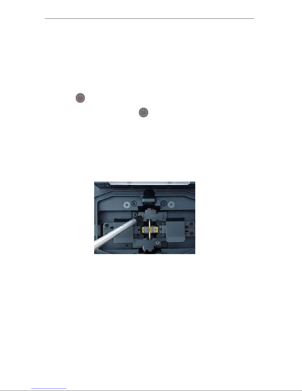
3.5 Replace Electrodes
Electrodes wear with use and also must be cleaned periodically due to
silica oxide buildup. It is recommended that the electrodes should be replaced
Page 19
16
after 1,000 arc discharges. When the number of arc discharges reaches a count
of 1,000, a message prompting to replace the electrodes is displayed
immediately after turning on the power. Using the electrodes without a
replacement will result in greater splice loss and reduced splice strength.
Replace Electrodes
<1> Press
button on the operator panel until the LED indicator turn from
red to green, release the button , now the machine is turned off.
<2> Remove the old electrodes and Method for tearing:
a. Loosen screw located on electrode cover.
b. Take electrode out of electrode cover.
(Electrode is fixed in the electrode cover)
<3> Clean the new electrodes with alcohol-impregnated clean gauze or lint-free
tissue and install them in the splicer.
<4> Place the electrode cover and tighten screw
Do not pull out night light wiring when replacing electrode.
The tightening of the screw should not exceed the strength of fingers.
Page 20

17
3.6 Set Calendar
This function sets the date and time in the calendar incorporated in the splicer.
<1> In theMaintenance Men1Menu, press
or and move the
cursor to select the [ Calendar ]
<2> Press to enter [Current Calendar] interface. Move the cursor to
select the item to be changed. Press
to adjust the value.
<3> After completion of calendar setting, press . The date and time are
stored.
4. Change the spare lithium battery pack
Change the spare battery according to the following procedures.
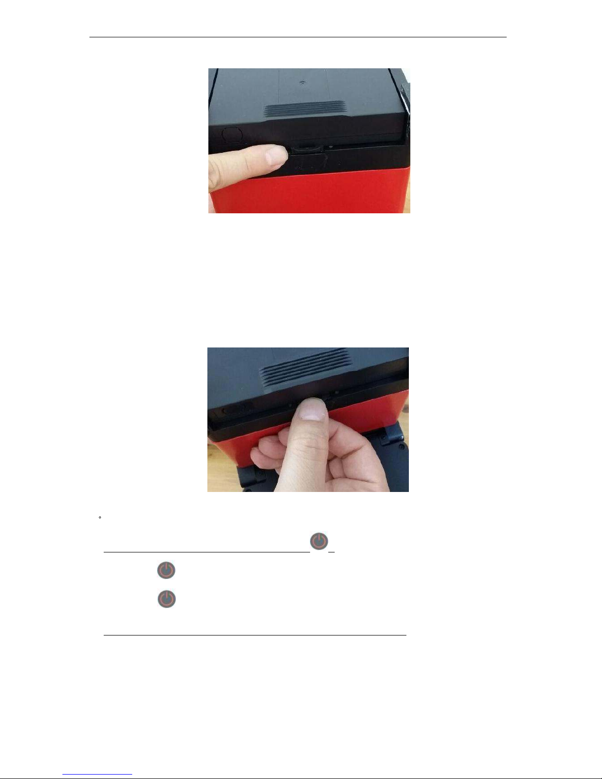
4. 1 Open the cover of the battery case
Lean the Fusion Splicer; open the cover of the battery case which is
at the bottom of the Fusion Splicer. See the following picture:
4. 2 Remove the old battery
Remove the lithium battery pack from the power module of the
Fusion Splicer;
Page 21
18
4 . 3 Place new battery pack
Aligning the card slot, place new battery into the power module and
make sure it is plugged in tightly, then close the cover of the battery
case which is at the bottom of the Fusion Splicer.
5
Power Supply
Power does not turn off when pressing
Press
and hold the key until the LED color changes from red to green.
Release to shut off the machine.
Few splices can be made with a fully charged battery pack
The battery pack uses chemical reaction. The capacity decreases at low
temperature, especially at lower than 0 degree.
At high altitude, the arc discharge current is increased. In this condition,
Page 22

19
battery power degrades faster due to large power consumption.
The AC/DC adapter is not the model supplied by the Company, or the
charging time is not long enough.
“CHARGE” LED on AC adapter blinks during battery recharge
Atmospheric temperature is too high (more than 50 degrees C), or the
battery pack is charged under exposure to sunlight.
The battery pack has a fault or has reached the end of its service life.
Install a new battery pack. If the LED blinks again after install, contact
your nearest sales agency.
The AC/DC adapter is not the model supplied by the Company.
Page 23

20
Addenda A:
Summary of quick operating
I. Preparing
1. Verify that the machine is plugged in power or the battery capacity is
enough; then press
and hold the key until the machine is booted.
2. In the standby mode, press to enter “Splice Menu” menu. Move
the cursor to [Operation Options]; press
to enter. Set [Auto Start]
[pause 1],[pause 2] respectively as “ON”,“OFF”,“OFF”.
3. Discharge Calibration*
Discharge calibration is needed because constant changing of
atmospheric conditions such as temperature and pressure, and the
long service of the machine creates variability in the arc temperature
and position.
Step of discharge calibration:
In the [ Ready ] mode, press
to enter “Splice Menu” menu.
Then prepare and place fiber according to the method described in
fiber preparation. Close the wind protector. Press to enter [Arc
Calibration]. Discharge calibration automatically starts. The user is
recommended to repeatedly prepare and place fiber in discharge
calibration interface, until the “Step II of discharge calibration
completed” message is displayed for three times.
Note:* Discharge calibration is needed only arc power fluctuates strongly;
it is not necessary upon boot every time. After discharge
calibration is completed, the machine will adjust the arc discharge
current according to the Calibration results to ensure fusion quality.
Page 24

21
. Fiber preparation
1. Put the tube over one end of the fiber.
2. Use fiber stripping pliers to strip fiber coating layer, the length of which
is 30-40 mm. Use gauze dipping with alcohol or wadding to wrap the
fiber, and then clean the bare part.
3. Use a fiber cleaver to cut the fiberBare fiber length is 16 mm around.
4. Put the finished fiber in the Fusion Splicer. Cross-section of fiber can not
touch other things.
. Cover the wind protector, then the fiber fusion automatically starts and
the splicing loss is displayed.
. Reinforce the fusion point.
1. Transfer fiber with protection sleeve from V-grooves to tube heater;
2. Make sure the splice point is located at the center of the protection sleeve.
Put the tube at the center of the heater.
3. Press
to start tube heating. The buzzer beeps and the HEAT LED
turn off when tube heating is completed.
4. Remove the tube from the heater when the heater is cool. The whole
process of Fusion Operation is completed.
. Repeat Step II, III, IV to continue splicing.
Page 25

22
Addenda B:
Guarantee period and limits
The following occurs, not covered under warranty
Malfunction or damage caused by user’s inadvertent actions (including
physical damage, damp short circuit) .
Product damage caused by nature disasters (earthquakes, fires, floods,
lightning, typhoons, etc.) or force majeure.
Other failure or damage due to improper use, or improper installation, or
configuration use of non-original batteries and accessories or other
external factors (such as voltage instability) .
Unauthorized disassemble or repair.
Consumable parts (such as electrode, cleaver blade, carrying case of
fusion splicer, etc.) .
Before shipping the splicer, please consult us or nearest sales agency first.
Necessary information needed for repair
(please affixes the information as follows)
<1> Your full name, section, division, company, address, phone number, fax
number and e-mail address.
<2> Model name and serial number of the splicer
<3> Problems encountered
What problems did your splicer get into and when?
What is its present operational state?
The state of the monitor and the contents of the relevant error message
and etc.
Page 26

 Loading...