

FiberLabs OTM-1550 Operating Manual
Technical passport / OTM-1550
12-2016-v4
OTM-1550
1550nm Externally Modulated Optical
Transmitter Operating Manual

Technical passport / OTM-1550
12-2016-v4
2
Table of Contents
TABLE OF CONTENT S ..................................................................................2
SAFETY INSTRUCTION.................................................................................3
1. OVERVIEW..................................................................................................4
1.1 About This Manual...............................................................................................4
1.2 Product Description.............................................................................................. 4
1.3 Product Applications ............................................................................................5
2. TECHNIQUE PARAMETERS......................................................................6
2.1 Optical Parameters ...............................................................................................6
2.2 Model Test Indicators........................................................................................... 6
2.3 Test Condition ......................................................................................................7
2.4 Technical Data Sheet ............................................................................................ 7
3. PANEL INTERFACE AND MENU SYSTEM DESCRIPTION.......................7
3.1 Front Panel ...........................................................................................................7
3.1.1 Indicator Description .....................................................................................8
3.2 Rear Panel ............................................................................................................8
3.3 Power Module ......................................................................................................8
3.3.1 220V Power Module...................................................................................... 8
3.3.2 48V Power Module........................................................................................9
3.4 Menu Operation....................................................................................................9
3.4.1 Main Menu.....................................................................................................9
3.4.2 Display Menu...............................................................................................10
3.4.3 Set Menu...................................................................................................... 11
3.4.4 Alarm Menu .................................................................................................12
3.4.5 AGC Mode................................................................................................... 12
3.4.6 MGC Mode..................................................................................................12
3.4.7 Frequency Adjust ITU in DWDM...............................................................13
3.4.8 SBS Suppression Adjustment ......................................................................13
4. INSTALLING THE OTM-1550 OPTICAL TRANSMITTER ........................14
4.1 Receiving and Inspecting ...................................................................................14
4.2 Precautions .........................................................................................................14
4.3 Mounting OTM-1550.........................................................................................15
4.3.1 Mounting the OTM-1550 in the Rack .........................................................15
4.3.2 Connecting the RF Cables ...........................................................................15
4.3.3 Connecting the Optical Fiber Cables...........................................................15
4.3.4 Connecting the Ethernet Cable .................................................................... 16
4.3.5 Connecting Power........................................................................................ 16
5. COMMUNICATION SETUP.......................................................................17
5.1 RS232 Communication Interface Description ...................................................17
5.2 Set up the Hyper Terminal.................................................................................. 17
5.3 Operating Parameters Configuration..................................................................19
5.4 Remote Monitoring: SNMP ...............................................................................22

Technical passport / OTM-1550
12-2016-v4
5.5 WEB Network Management .............................................................................. 22
6. MAINTENANCE AND TROUBLESHOOTING ..........................................25
6.1 Cleaning Fiber Optic Connectors.......................................................................25
6.1.1 Cleaning Patch Cord or Pigtail Fiber Optical Connectors........................... 25
6.2 Troubleshooting..................................................................................................26
6.3 After-sales Service Description .......................................................................... 27
6.4 Disclaimer ..........................................................................................................27
Safety Instruction
3

Technical passport / OTM-1550
12-2016-v4
4
1. Overview
1.1 About This Manual
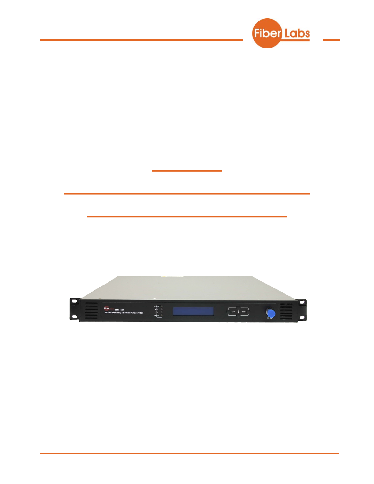
This instruction manual is a complete guide to install and operate the (1RU) OTM-1550 series
1550nm externally modulated optical transmitter. Please read the entire manual before beginning
installation.
This manual applies to OTM-1550 series externally modulated optical transmitter.
• Chapter 1 gives general information about the OTM-1550 series 1550nm externally modulated optical
transmitter.
• Chapter 2 describes the complete technical specifications of OTM-1550.
• Chapter 3 describes the front/rear panel interfaces and menu system.
• Chapter 4 tells you how to install OTM-1550 series externally modulated optical transmitter.
• Chapter 5 tells you the communication setting of OTM-1550.
• Chapter 6 describes maintenance and what to do in the event of problems.
1.2 Product Description
OTM-1550 series optical transmitter is a 1550nm DFB laser externally modulated transmitter. It is
specially developed for the CATV signal that satisfies HFC network, and the long-distance transmission
of cable phone and cable data.
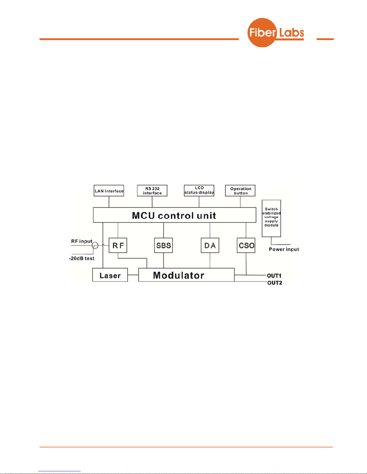
Working principle
OTM-1550 series transmitter has 7 function modules: RF control, DFB laser, optical modulator, SBS
control, CSO control, communication/display control and power supply.
Automatic gain control circuit (AGC) or manual gain control circuit (MGC) amplifies the RF signal.
AGC or MGC control makes the optical modulator maintain a suitable input level. Use the detected RF
root-meansquare(RMS)-total power to calculate the optical modulation index(OMI).
In general we recommend using the AGC function, and special users can use the MGC function to
adjust the CNR/CSO/CTB performance indexes.
The core of transmitter is the optical modulator. The 1550nm signal input the optical modulator, make
the laser intensity changed follow the external RF signal voltage, and then generate the AM optical signal.
Technical passport / OTM-1550
12-2016-v4
Stimulated Brillouin Scattering (SBS) occurs, when the optical input power is greater than a certain
threshold value. SBS generate the lower frequency backscattered light which will attenuate the
transmission light and return to the laser while destroying its performance. Causing optical power
fluctuation, generates large noise, and seriously deteriorates the system carrier to noise ratio (CNR). To
improve the SBS threshold, OTM-1550 series optical transmitter adopts SBS control technology which is
independent researched and developed by ourselves. The threshold value can be set up to 19dBm.
The optical modulator has a two-way optical signal output. Parts of that signal are routed to an InGaAs
photodiode. This detection of the optical signal has two functions:
1) Detect whether the laser is normal working. Once the output optical power is 2dB lower than standard
power, alarm will be set off.
2) Detect CSO distortion to optimize the bias point of the optical modulator. For working normal the
detector circuit needs at least two carrier signal inputs with an interval of 24MHz. There is a CSO
initialization program in the boot process. If the CSO install failed, the RF indicator will flash red, see
details in 6.2 T r oubleshooting.
Block Diagram
1.3 Product Applications
• High-performance long-distance transmission
• High-power distribution network
• Redundancy loop architecture
• FTTx network
• RFOG application
• DWDM network
5

Technical passport / OTM-1550
12-2016-v4
6
2. Technique Parameters
2.1 Optical Parameters
Item Unit Value
Optical Wavelength nm
1545~1560 (or specified by the user)
Side-mode Suppression ratio dB >30
Relative Intensity Noise dB/Hz <-160
Wavelength Adjustment
Range
GHz +/-50GHz
Optical Power dBm 2x5, 2x7, 2x8, 2x9, 2x10
SBS Threshold Value dBm
+13~+19 (Continuously adjustable)
Laser Linewidth MHz 0.3
2.2 Model Test Indicators
Test Model C42 D59 D84 D84
Channel Plan CENELEC42 PAL D59 PAL D84
PAL D
Channel Number
TV/FM/QAM64
42/0/0 59/0/0 84/0/0 30/0/48
Bandwidth Noise 5 5 5 5
CNR Tx/Rx 55.5 54.0 52.5 54.5
CNR Link 1 55.0 53.5 52.0 54.0
CNR Link 2 53.0 52.5 50.5 52.5
CNR Link 3 50.5 50.5 49.0 51.0
CSO Tx/Rx and Link 1 64 65 65 70
CSO Link 2 63 65 65 70
CSO Link 3 62 64 63 65
CTB 65 65 65 68

Technical passport / OTM-1550
12-2016-v4
2.3 Test Condition
First stage
EDFA
First
paragraph
fiber length
Second
stage
EDFA
Second
paragraph
fiber length
RX
SBS
(dBm)
Tx/Rx No No No no 0dBm 13.5
Link 1 No 35km no no 0dBm 13.5
Link 2 16dBm 65km no no 0dBm 16
Link 3 13dBm 50km 13dBm 50km 0dBm 13.5
Rx with 8 pA/ÖHz input noise current density; EDFA with 5dB noise figure; RF input level at 80 dBμV / TV channel;
2.4 Technical Data Sheet
Item Unit Technical Parameters
RF range MHz
47~1003
RF flatness dB +/-0.75
RF return loss dB >16
RF input impedance Ω 75
RF input connector type F type
Rated input level dBµV 80
Input level range dBµV 78~96 (AGC mode, modulating signal)
AGC control range dB
+3~-3
MGC adjustable range dB 0~15
Optical connector SC/APC, FC/APC
Operating temperature °C
-5~45
Storage temperature °C
-30
~+70
90~265VAC
Power Source
Specification
V
36~72VDC
Consumption W ≤60
Dimension mm
483(L) × 455(W) × 44(H)
Total Weight kg 5.5
3. Panel Interface and Menu System Description
3.1 Front Panel
1
Power indicator
2
AGC ind
icator
3
RF modulation degree
indicator
4
Laser indicator
5
LCD
6
ESC key
7
Technical passport / OTM-1550
12-2016-v4
7
UP
key
8
DOWN key
9
Enter key
10
-20dB RF input test port
11
RF input port (or on the
rear panel, optional)
12
Optical output interface A (or
on the rear panel, optional)
13
Optical output interface B (or
on the rear panel, optional)
3.1.1IndicatorDescription
One power supply LED yellow
Power indicator
Two power supplies LED green
AGC mode LED green
AGC indicator
MGC mode LED off
Normal LED green RF modulation degree
indicator
Abnormal LED flash red
Bias current, cooling current and
output power are all normal
LED green
Laser indicator
At least one of bias current,
cooling current and output power
is abnormal
LED flash red
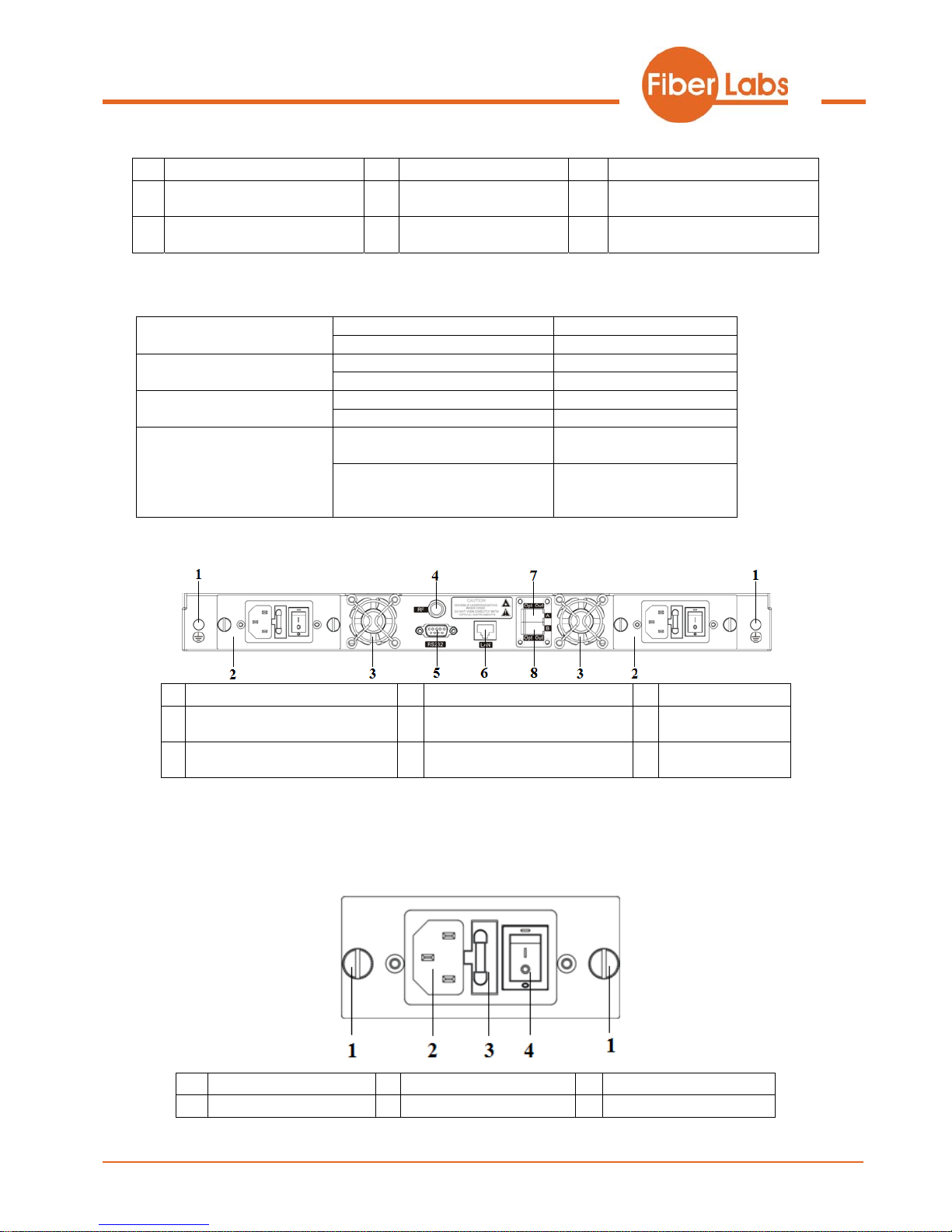
3.2 Rear Panel
1
Ground stud
2
Power module
3
Fan
4
RF input port (or on the front
panel, optional)
5
RS232 interface
6
LAN interface
7
Optical output interface A (or
on the front panel, optional)
8
Optical output interface B (or
on the front panel, optional)
3.3 Power Module
3.3.1220VPowerModule
1
Mounting screws
2
220V power outlet
3
Fuse
4
Power switch
8
Technical passport / OTM-1550
12-2016-v4
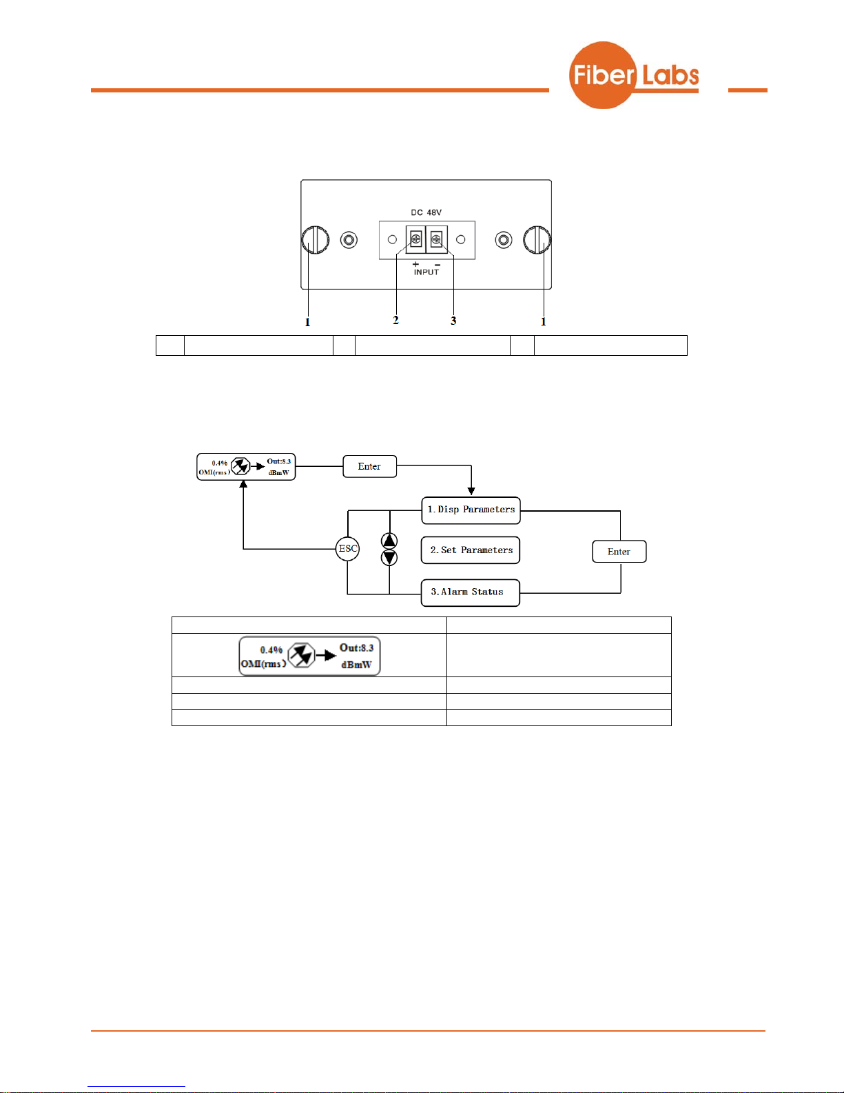
3.3.248VPowerModule
1
Mounting screws
2
+ Positive terminal block
3
- Negative terminal block
3.4 Menu Operation
3.4.1MainMenu
Displayed parameters Comments
Boot display
1.Disp Parameters
Menu one: Display parameters
2.Set Parameters
Menu two: Set parameters
3.Alarm Status
Menu three: Alarm status
9
 Loading...