

Page 1

OPTICAL TALK SET USER MANUAL
Page 2

TABLE OF CONTENTS
PAG E
LIGHT SOURCE
1.0 Overview ............................................................ 1
2.0 Features .............................................................. 1
3.0 Applications ...................................................... 2
4.0 Specications ................................................... 2
5.0 Standard Conguration ................................3
6.0 Operational Instructions .............................. 3
7.0 Troubleshooting .............................................. 4
8.0 General Maintenance .................................... 4
9.0 Quality Assurance ............................................ 5
Page 3
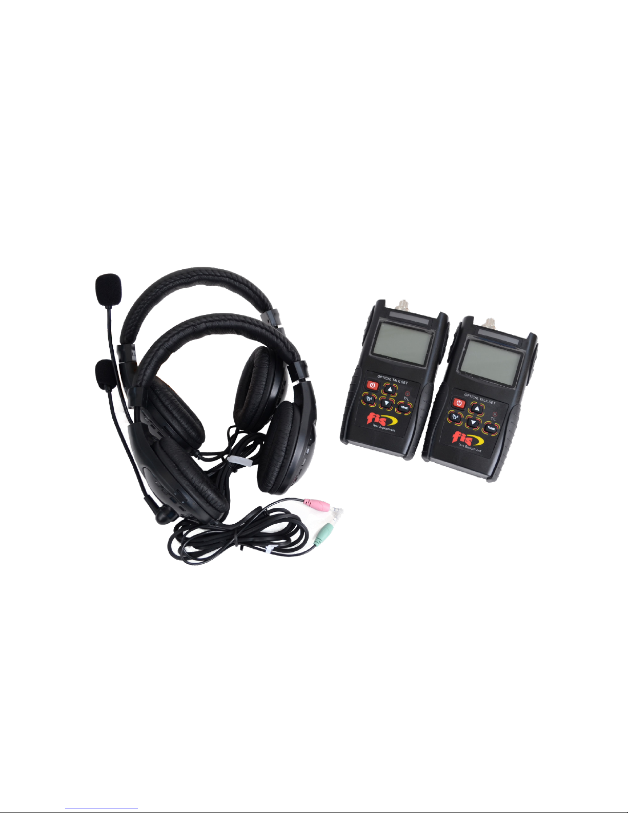
1.0 Overview
This is an intelligent and ecient instrument that combines in one
set, the functions of both a digital optical phone and a stabilized light
source. It is widely used in operations of installation, optical testing,
maintenance and ber attenuation testing and ideally used in data
network, CATV and Telecommunication networks. It can carry out
full-duplex communication with a high quality connection and not be
aected by distance. With a comfortable hand held design, the user
can operate this optical phone and tester with ease.
2.0 Features
• Full-duplex digital communication with high quality conversation
connection and low background noise
• Combines functions of both a digital optical phone call and a
stabilized light source.
• Large LCD display with backlight
• Low battery power indication
• Laser source has modulations of 270Hz | 330Hz | 1KHz | 2KHz
FIS OPTICAL TALK SET
1
Page 4

Remark: *Laser source in modulation, may inuence the stability of the
output power, this is normal.
** The battery operation time is dened under the back light o, if the
backlight on, the operation time may shorter.
2
4.0 Specications
Product Name Optical Talk Set
Wavelength (nm) 1310 (A) / 1550 (B)
Fiber type SM & MM
Distance (km) 80
Laser Device type FP - LD
Output adjustment (dB) 1
Output power (dBm) -5 ~ -15
Output stability (dB,
30min, 20°C)*
< 0.05
Modulation CW, 270Hz, 330Hz, 1KHz, 2KHz
Connector type FC & SC (PC)
Battery 3*AA, 1.5V
Battery operation time (h)
**
30 (Talk set function) 50 (laser
source function)
Work temperature -10 ~ +60
Storage temperature -25 ~ +70
Dimension (mm) 161 × 90 × 44
Weight (g) 225
3.0 Applications
• Maintenance in Telecom
• Maintenance CATV
• Fiber Optic Lab Testing
• Other Fiber Optic Measurements in remote areas
Page 5
3
5.0 Standard Conguration
Items Name No.
1 Optical Talk Set 1 Pair
2 User manual 1 pcs
3 1.5V AA battery 6 pcs
4 Cleaning Cotton swab 1 bag
5 Carry Bag 2 pcs
6.0 Operational Instructions
1. Install 3 AA batteries in each talk set.
2. Screw out or unplug the dust cap on the laser port, connect the
patch cord to it, and connect the microphone and earphone with
the related 3.5mm ports.
3. Press the power key 1 second to open the tester, the tester will default to be in talk set mode and “PHONE” will display on the screen.
4. When the signal is detected, “CALL” will display on the screen,
When the LED light turns to green, the communication is set up
between the two talk sets, you can now communicate via the microphone and headphones.
5. When you turn o the power, or shift to the laser source working
mode, it will end the talk set mode.
6. In laser source working mode, use sign to choose the modulation, shift between CW,270,330,1000,2000Hz.
7. Adjust the output power via the up and down key, one time press
this key will have 1dBm adjustment of the output power, and the
currently output power value display on the screen.
8. This tester has 10 minis. auto-o function, short press the power
key when the tester’s on, to disable the auto-o function, and
sign will disappear.
9. Long press the power key 2 seconds, to turn o the tester.
10. Put on the dust cap, to keep the laser port clean, and keep away
from children.
Page 6

4
7.0 Troubleshooting
Problems Reasons Solutions
Low voice
The voice
controller is turned
down
Turn up the voice
controller
Low and not clear
voice
FC/SC connector is
not clean
Clean the
connector use the
cotton swab.
Output power
does not reach the
requirement
1. FC/SC connector
are not clean
1. Clean the
connector with
the cotton swab.
2. APC ferrules
cannot be used
2. Use correct
connectors.
The output power
value is unstable
1. The tester has
just turned on,
laser device still
not stabled.
1.Open the tester,
and use it after
3 minis
2. The laser port is
dirty/dusty.
2. Clean the laser
port
8.0 General Maintenance
• Always keep the connector ports of your power meter clean.
• Do not use APC (green) ber connectors, otherwise, it will damage
the interface of detector that will greatly aect the performance of
the unit.
• Try to use only the adaptors supplied.
• Once not in use, make sure dust-proof cap is placed properly over
the optical ports.
• Carefully plug in/out ber connectors/adapters to avoid scratches
on the port of the power meter.
• Perform regular cleanings on the optical port of power meter,
please clean with cotton swabs and/or alcohol properly.
Page 7

5
9.0 Quality Assurance
We do not approve users to repair this instrument by themselves.
1. The instrument will be warranted for 12 months from the date of
delivery.
We provide a warranty for a period of 12 months for all products
from the date of delivery. During warranty period, if there are any
problems with the product, we will repair or replace with a new
one. But in any case, the cost of will not exceed the purchasing
price of the product.
2. If a breakdown occurs when using the equipment, please do not
open the outer cover. Please immediately contact our technical
department or a sales person for possible solutions.
3. If the fault is caused by production limitation, we will replace a new
equipment or service at no cost. This warranty only applies for the
normal use, excluding:
1. Repair the unit or change settings without the necessary
authorization.
2.
Improper usage, neglect, accident, causes external to the
product or other factors beyond the control of us.
Page 8

161 Clear Road
Oriskany, NY 13424
Ph: 315.736.2206 Toll Free: 1.800.5000.FIS(347) Fax: 315.736.2285
www.berinstrumentsales.com email: info@berinstrumentsales.com
 Loading...