

Page 1
www.fiberfox.co.kr
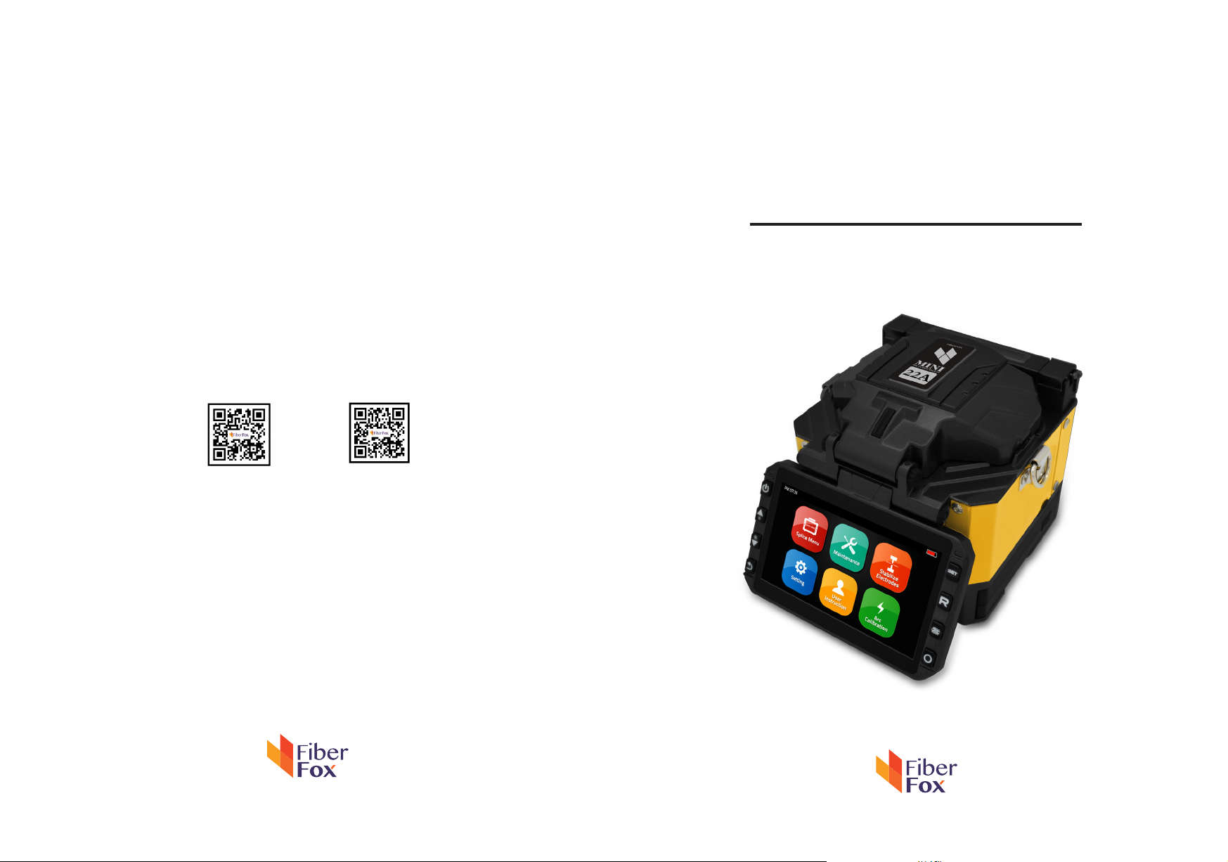
Mini 22A
User Manual
website youtube
Sales : [email protected]
Technical Support : [email protected]
80, Dongseo-daero 179beon-gil,
yuseong-gu, Daejeon 34159, Korea
www.fiberfox.co.kr
Page 2

Contents
Introduction
·
Technical specifications
·
Splicer description & Part name
·
How to the replace the fiber folder
·
Cleaning
·
Splice Program
·
- Stabilize Electrodes
- Arc Calibration
- Splice Menu
1) Splice Mode
2) Splice Option
3) Heater Mode
4) Data Storage
5) Menu Lock
6) Reset
- Maintenance
- Setting
1) System Setting
2) Language
3) Power Save Option
4) Set Calendar
4
4
6
7
7
8
8
9
10
11
13
14
15
18
19
20
21
- 2 -
Page 3

5) Password
23
6) System Information
Notice : Warning and Cautions
·
Appendix I
·
Appendix II
·
Appendix III
·
24
25
27
29
32
Important
FiberFox highly recommend that all users read this manual before operating Mini 22A.
This manual is valid for the recent software version.
Cautions
The Battery must be taken out of the splicer, when stored in the Hand carrying case.
- 3 -
Page 4
Introduction
Thank you for choosing Mini 22A FTTx Master from FiberFox. The Mini 22A with innovative design
and excellent manufacturing technology gives customers assurance of trust.
Exceptional splicing experience and new technology greatly reduces splicing and heating time.
Advanced estimate method and clad alignment technique ensure the accuracy of the splice loss
estimation. Its small size, compact design and reliable protective casing make it suitable for any
operating environment. Dynamic operation interface and automatic splice mode give the custom-
ers great user-friendliness. For more information, please contact your local distributor or visit our
website at www.fiberfox.co.kr
This manual explains the features, specifications, operation, maintenance and warnings about Mini
22A. The primary goal of this manual is to make the user very familiar with the splicer operation.
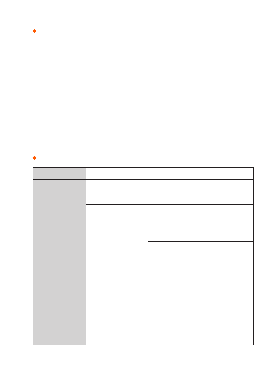
Technical specifications
Camera High precision dual camera
Display 4.3” wide color reinforced LCD
x150 : X&Y axis dual view
Microscope
Power Supply
Data Capacity
Splice Speed
x300 : X axis single view
x300 : Y axis single view
AC 100~240V
Splicer
Li-ion Battery DC 11.1V
Factory pre-set 11 ea
Splice Mode
Edit Mode 128 ea
Data Storage (Splicing result)
SM Quick mode (SQM) 7 Sec.
SM AUTO mode 9 Sec.
- 4 -
50~60HZ
DC 9~14V
5,000
Max 10,000
Page 5

Applicable Sleeve
Standard : 20, 25, 30, 35, 40, 60mm
Custom : 4*32mm sleeve (For SOC)
Heating Time 8~900sec (Typical: 18sec)
Heater
Applicable
Fiber
Applicable
Cable
Splice Loss
Heater mode
Factory pre-set 4 ea
Edit Mode 23 ea
Standard 1 ea(Pre-installed)
Heating block
SOC Customized 1 ea(In Package)
Fiber count : Single core
Fiber Type : SM(ITU-TG.652)/ DS(ITU-TG.653)/ NZDS(ITU-TG.655)/
ITU-TG.657 A,B Type / MM(ITU-TG.651)
Fiber count : Single core fiber in cable
Applicable diameter : 0.25mm / 0.9mm / 2.0mm / 2.4mm / 3.0mm
Applicable buffer Diameter
: Cladding diameter : 80~150µm, Coating diameter : 100~1,000 µm
SM : 0.02dB
MM : 0.01dB
DS : 0.05dB
NZDS : 0.05dB
G.657 : 0.02dB
Reliability
Operating
Condition
Storage
Condition
Altitude 0~5,000M
Humidity 0~95%
Temperature
Wind Speed 15m/s
Humidity 0~95%
Splicer
Temperature
Battery
- 5 -
-10
-20~60
-20~40
~50
℃
℃
℃
Page 6
Splicer description & part name
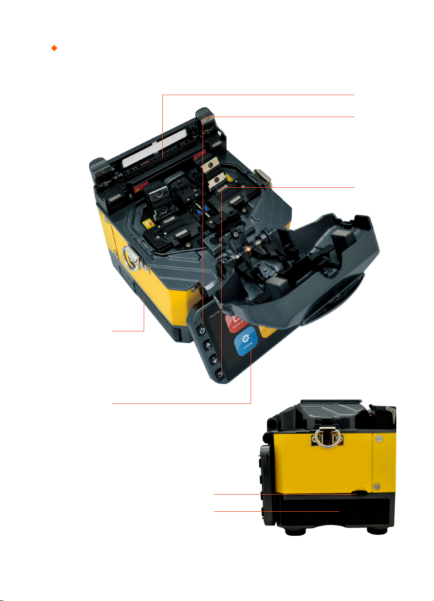
Power Supply / Battery
Sleeve Heater
ON/OFF Button
Return Button
Monitor
Micro HDMI Port
Connector for Charging Battery
- 6 -
Page 7
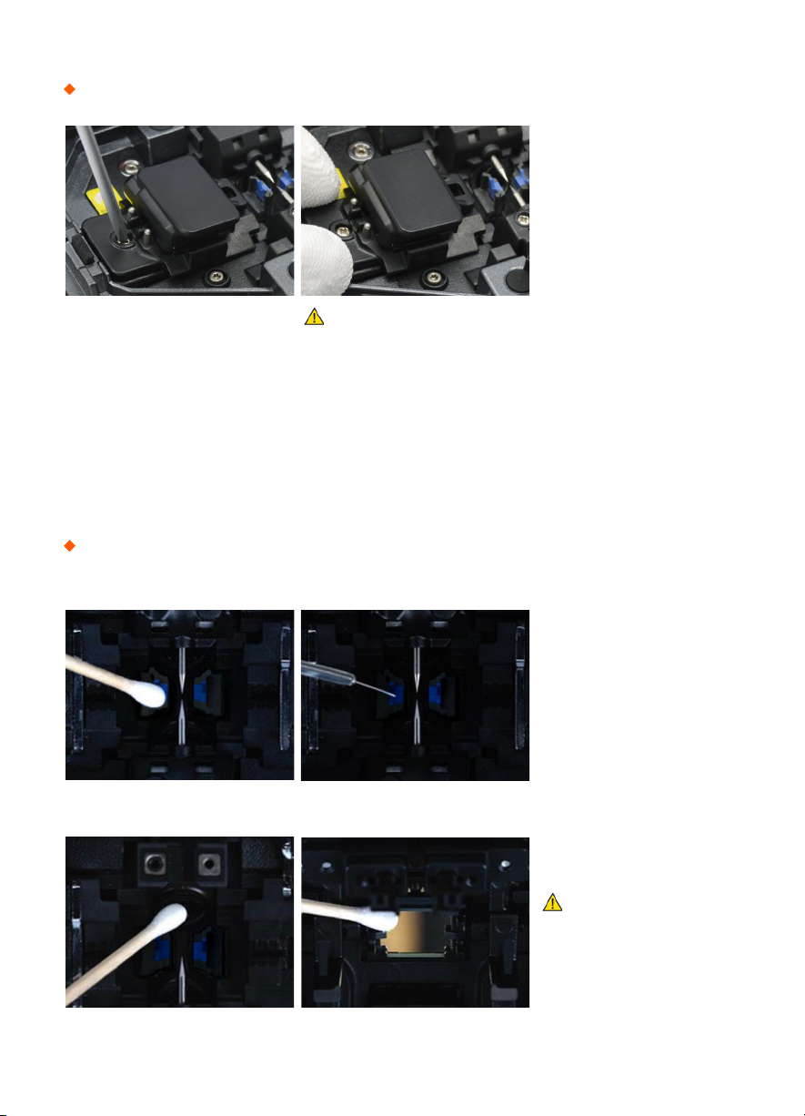
How to replace the fiber holder
1) Loosen the screws
2) Take out the universal holder
3) Replace compatible with holder
4) Tighten the screw
Caution
1) The unscrewed screws remain in the holder
(Do not remove the screws out)
2) Do not screw down the holder too tight
Cleaning
V-Grooves
Lens Mirrors
Check fiber after cleaning
with cotton swab
- 7 -
Caution
1) Do not disturb
the electrode tips
2) Use only 99% or better
purity alcohol
Page 8
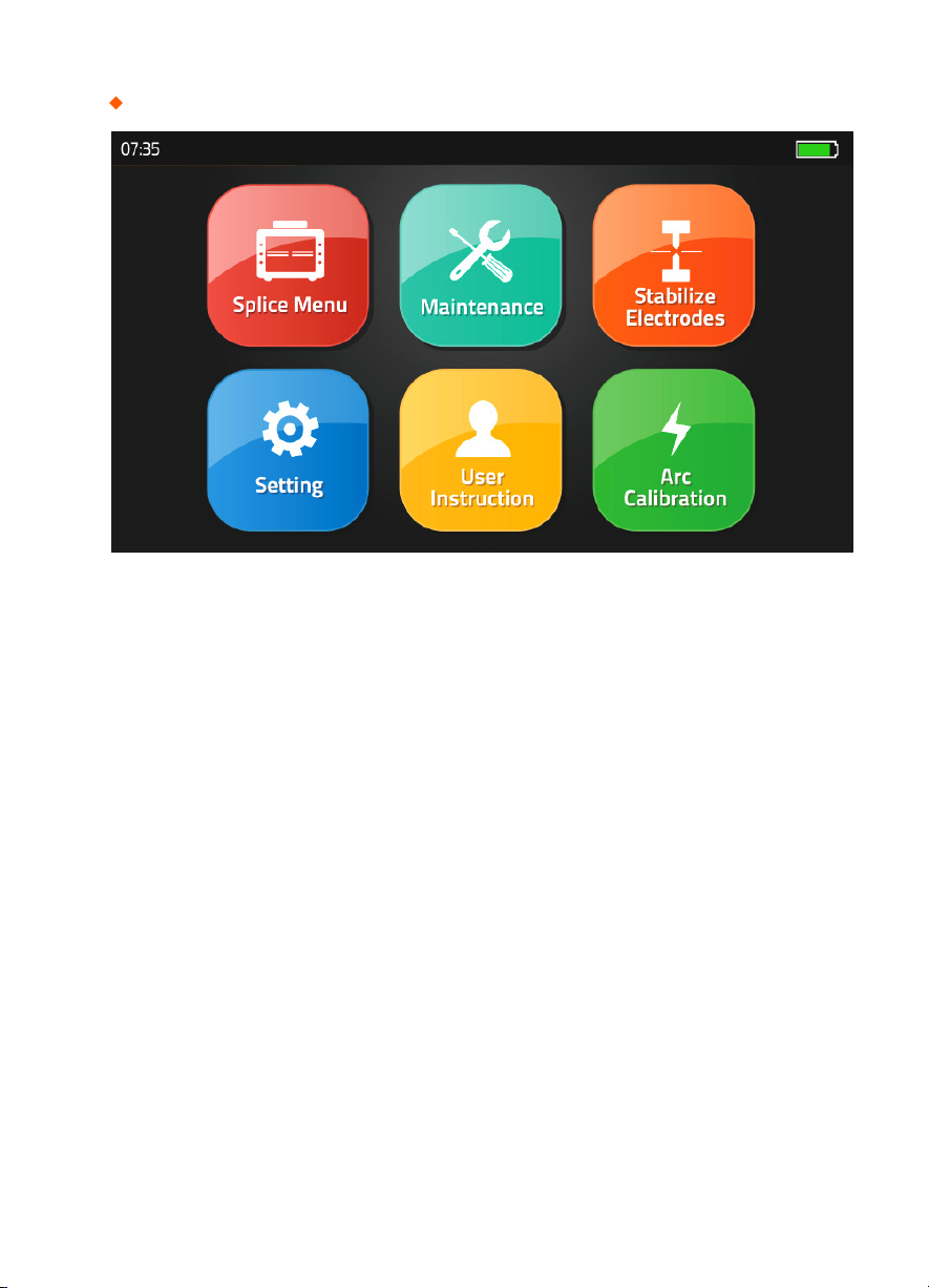
Splice Programs
Splice Menu, Maintenance, Stabilize Electrodes, Setting, User Instruction, Arc Calibration
[Stabilize Electrodes]
In the event of sudden change in environmental conditions or after cleaning electrodes, the arc power
sometimes becomes unstable, resulting in higher splice loss. This is especially a concern when the
splicer is moved from lower altitudes to higher , it takes time for the arc power to stabilize. In this case,
stabilizing electrodes will expedite the process to normalize the arc power. If many tests are required
to get the “Test ok” message appearing the [Arc calibration], use this function as well.
[Arc Calibration]
Atmospheric conditions such as temperature, humidity, and pressure are constantly changing, which
creates variability in the arc temperature. This splicer is equipped with temperature and pressure
sensors that are used in a constant feedback monitoring control system to regulate the arc power
at a constant level. However, changes in arc power due to electrode wear and glass adhesion cannot
be automatically corrected. Also, the center position of arc discharge sometimes shifts to the left or
to the right. In this case, the fiber splicing position has to be shifted in relation to the arc discharge
center. It is necessary to perform an arc power calibration to eliminate these problems.
Note : Performing [Arc calibration] function changes the arc power “Factor” value. The factor value is
used in the algorithm program for all splicing. The arc power value will not change in the splice modes.
Standard Factor value is changed within 11 ± 2, It shows “Complete” word. otherwise, it shows
*
“Retry” which means failure arc test, User needs to reload the optic fiber, retry arc calibration test.
- 8 -
Page 9
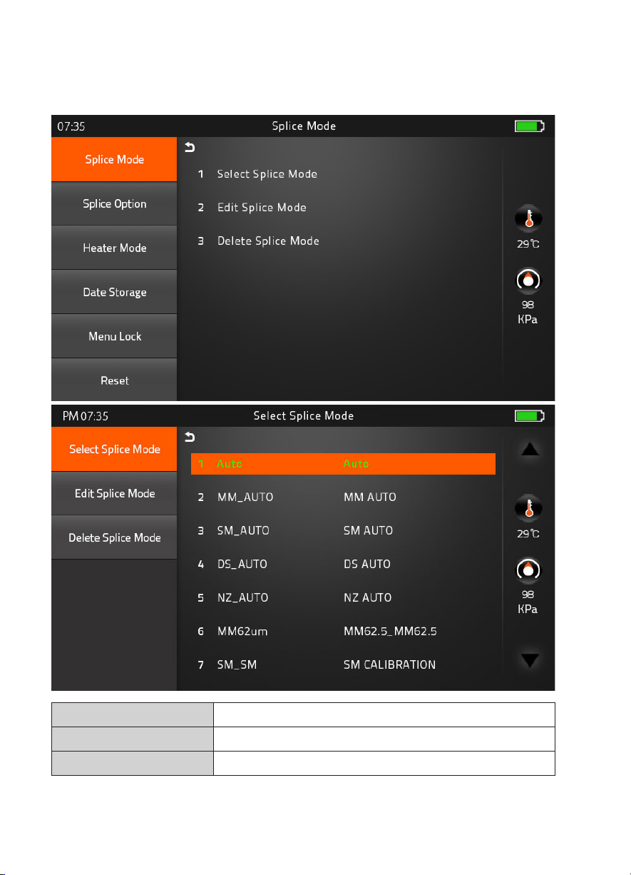
[Splice Menu]
1) Splice Mode
Factory Pre-Set Mode 11 ea
User Mode User Edit : 128 ea
Delete Splice Mode -
- 9 -
Page 10

2) Splice Option
Auto Start
ON : Automatic splicing procedure
OFF : Manual Splicing procedure
Pause 1
(Press Motor)
Pause 2
(Align Motor)
ON : Pause after the fiber gap position process
OFF : Proceeding without the pause
ON : Pause after camera focus & Axis alignment process
OFF : Proceeding without the pause
ON : Automatically proceed realignment
Realign After Pause 2
OFF : Proceeding without the pause
Ignore Splicing Error ‘splicing error’ message is not displayed
Fiber Image On Screen Select display structure for each splicing process
- 10 -
Page 11
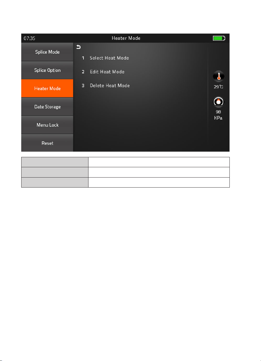
3) Heater Mode
Factory Pre-Set Mode 4 ea
User Mode User Edit : 23 ea
Delete Heater Mode -
- 11 -
Page 12
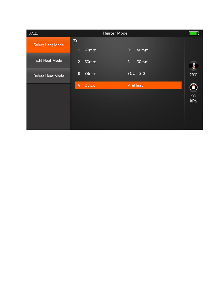
▶
Preheat Mode
It is performed for reducing heating time and rapid heating task. When it comes to turned
on program, red LED keeps blinking which means it is warming up the heater about 120 to
160℃ itself. After a few minutes, it is available to shrink the sleeve in 15 seconds (Refer to
60mm sleeve which used to perform in 20 seconds)
However, Please be attention, it wastes more the battery power than Normal heating
mode. (Normal Cycle is approximately 400, whereas, it performs 295 cycle)
- 12 -
Page 13
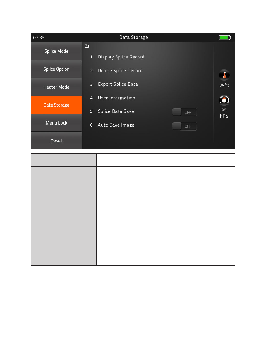
4) Data Storage
Display Splice Record Displaying your detailed splice record
Delete Splice Record -
Export Splice Data Downloading saved data (Splice record or Image)
User Information Record the work information into the data save file
ON : Automatic data save
Splice Data Save
* Image data is saved manually *
OFF : Do not save splice record
ON : Automatic data save
Auto Save Image
OFF: Manual data save
- 13 -
Page 14
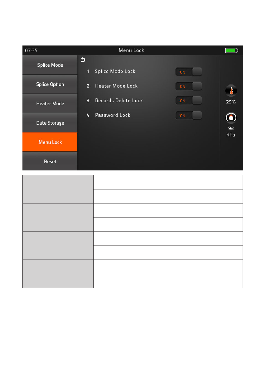
5) Menu Lock
Input password to access the sub-menu
ON : Disable ‘Splice mode’ edit
Splice Mode Lock
OFF : Enable ‘Splice mode’ edit
ON : Disable ‘Heater mode’ edit
Heater Mode Lock
OFF : Enable ‘Heater mode’ edit
Records Delete Lock
Password Lock
ON : Disable ‘Record mode’ edit
OFF : Enable ‘Heater mode’ edit
ON : Disable to change the password
OFF : Enable to change the password
- 14 -
Page 15
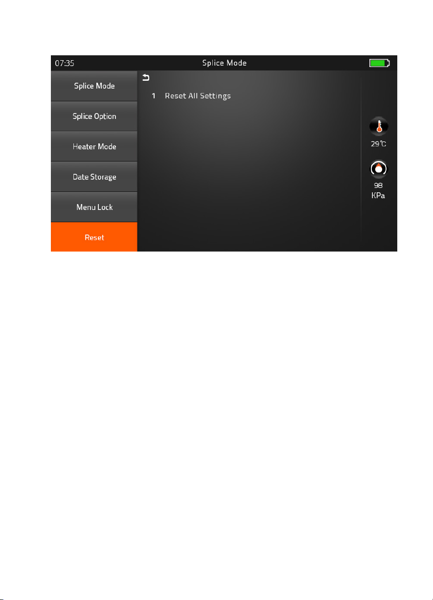
6) Reset
Unexpected the malfunction occurring on splicer, it is necessary to make reset all the
parameter through the reset mode. However, it is highly recommend to carry out the reset
function after discussed with a technician to reduce second problem.
Lower 1.34 version must try Reset function for applying new function of program on the
fusion splicer after upgrade process.
- 15 -
Page 16
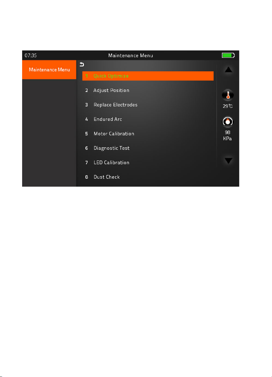
[Maintenance]
1) Maintenance Menu
▶ Quick Optimize
Quick & Easy overall maintenance
Automatic process ‘Focus Adjust > Motor calibration (Press) > fiber training’.
▶ Adjust Position
Find the optimized position of optic fiber especially Focus Motor position.
▶ Replace Electrodes
Instruction on how to replace electrodes
FiberFox recommendation
It is highly recommended to change the electrodes after every 5,000 splicing. *
After finished to use this menu, the current Arc Count is changed to ‘0’
▶ Endured Arc
Training for new electrodes adjustment
It occurs 30 times arc training for adjusting new electrodes function.
▶ Motor Calibration
Automatically calibrates the speed of all four motors
- 16 -
Page 17
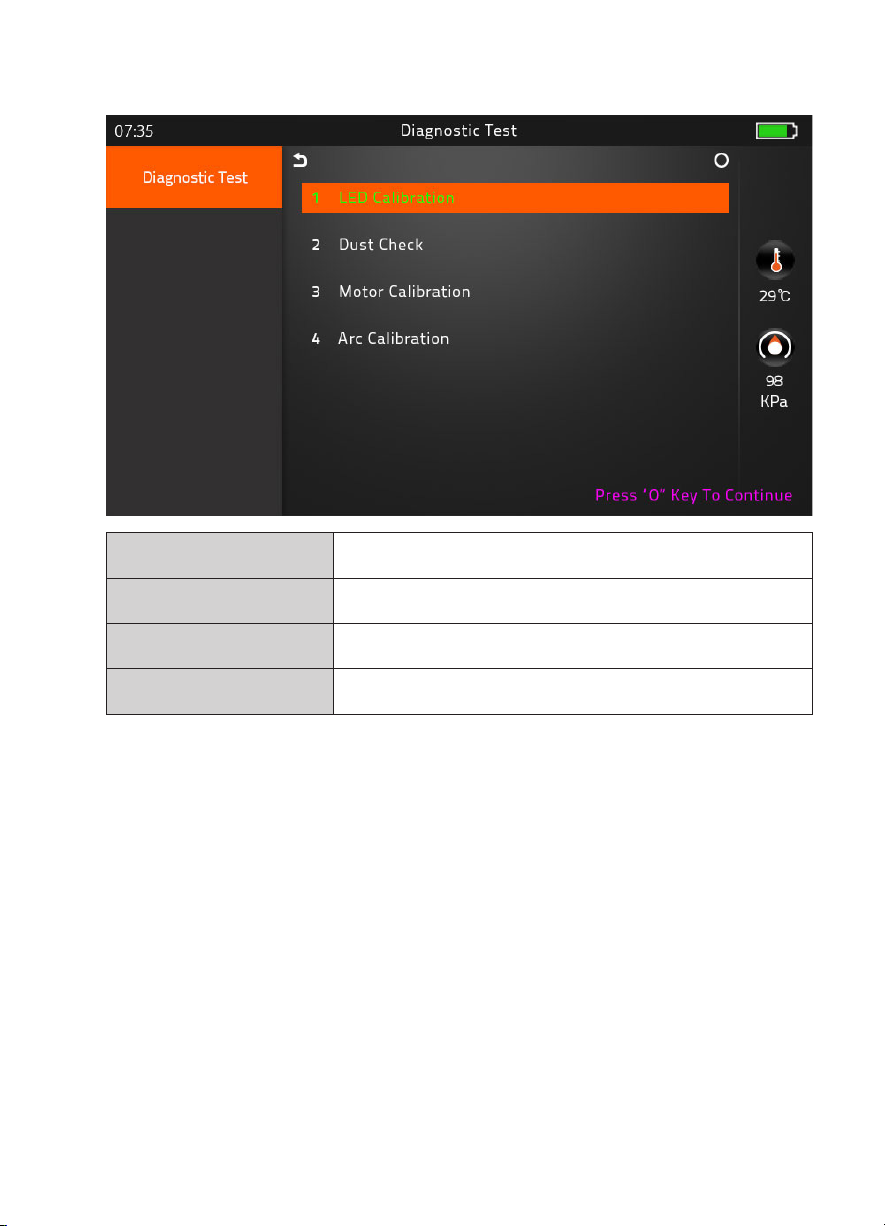
▶ Diagnostic Test
LED Calibration Measures and adjusts the brightness of LED
Dust Check Dust checking process
Motor Calibration Automatically calibrates the motor speed
Arc Calibration Automatically calibrates the Arc power
▶ LED Calibration
Measures and adjusts the brightness of LED
▶ Dust Check
Detects dust&contaminant causing improper splicing
In order to find out optimized position for splicing, the splicer analyses the fiber images being
transmitted by the optical camera & LED inside but dust or contaminant on the camera, lenses,
LED may cause inaccurate splicing results.
Therefore, the dust check process is recommended to proceed in case of frequent splicing fail
or high insertion loss.
- 17 -
Page 18
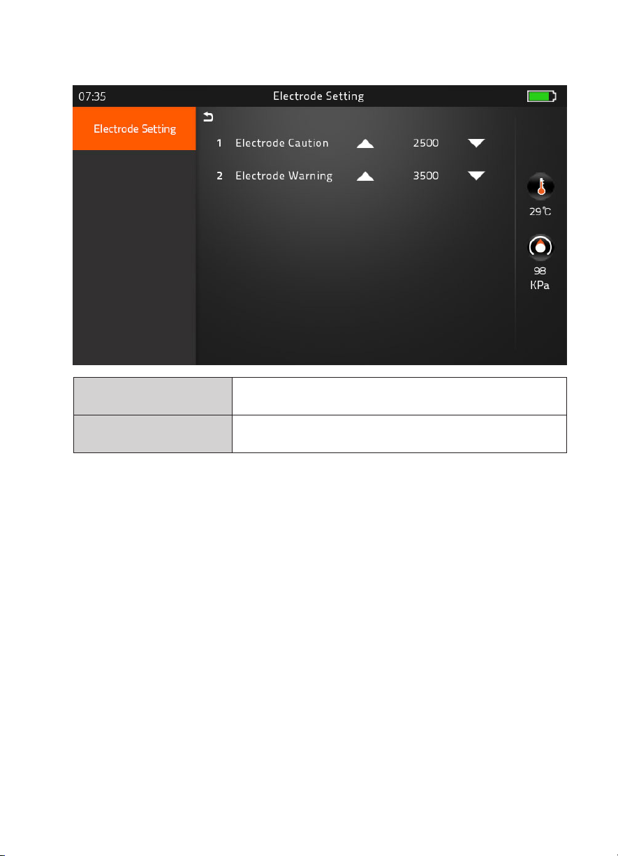
▶ Electrode Setting
Electrode Caution
Electrode Warning
Caution alarm will be displayed when it reach the number of
splicing cycle you set
Caution alarm will be displayed when it reach the number of
splicing cycle you set
- 18 -
Page 19

▶ Motor Drive
This checks the operation status of motors.
* Method : Chosen one of motor by Tapping in middle of motor name, And move to press up and
down arrow keys
▶ Update Software
Upgrade to the latest software version.
Procedure
1 Prepare the USB device.
2 Download the latest version software to the USB.
3 Link to the Splicer (Via link cable in the package).
4 Press “O’ Button to proceed with update.
5 Device will be rebooted once it is done.
6 Splice Menu > Reset (Format) > Input Password > Execute Format task
7 Execute the Quick Optimize > Stabilize Electrodes > Arc Calibration
- 19 -
Page 20
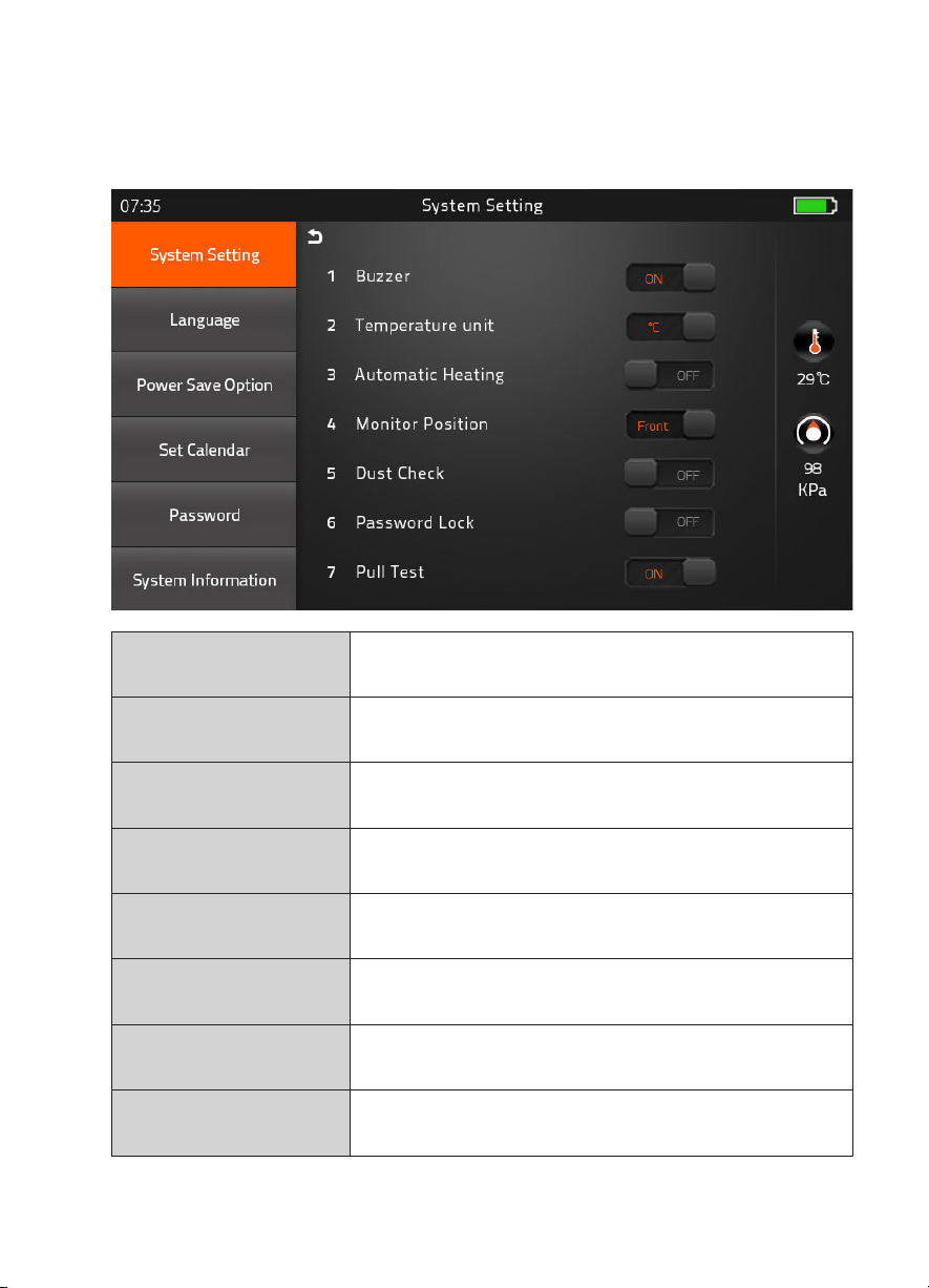
[Setting]
1) System Setting
Buzzer
Temperature Unit
Automatic Heating
Monitor Position
Dust Check
Password Lock
Pull Test
Calibrate Touch Screen
ON : Sound on
OFF : Sound off
℃
: Celsius
℉
: Fahrenheit
ON : Auto start
OFF : Manual start
Front : Normal direction display
Rear : Opposite direction display
ON : Check the dust density
OFF : Skip dust checking process
ON : Password is required to operate the device
OFF : No password is required
ON : Automatic pull test processing after splicing
OFF : Skip pull test process
Automatic calibrate touch function to occur
unstable control of touch screen
- 20 -
Page 21
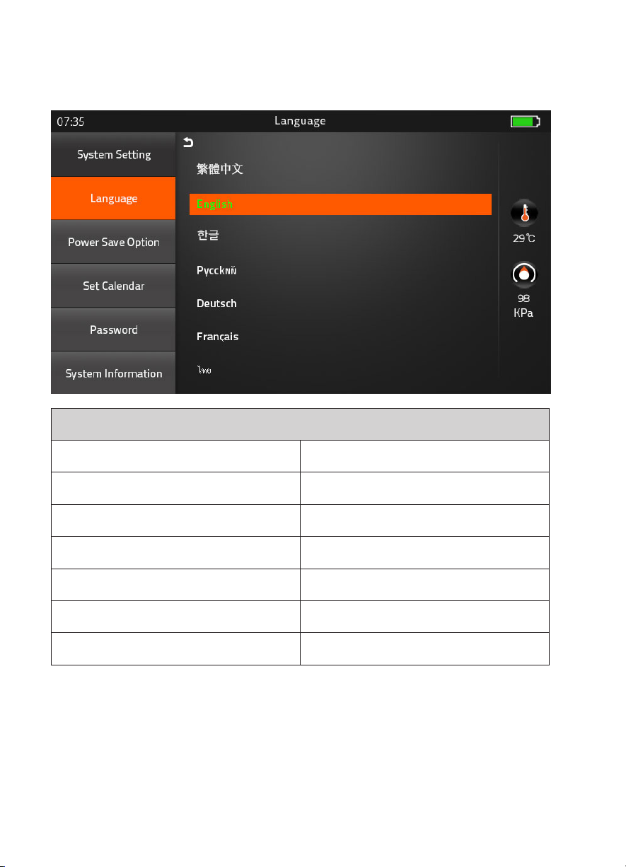
2) Language
Set your own language.
繁体中文 Việt
Language Available
English ةيبرعلا
한글
Русский Italiano
Deutsch Português
Français یسراف
ไทย
There are included over 30 languages option on the fusion splicer.
Please request to sales department if your language is not contained.
- 21 -
Español
Page 22
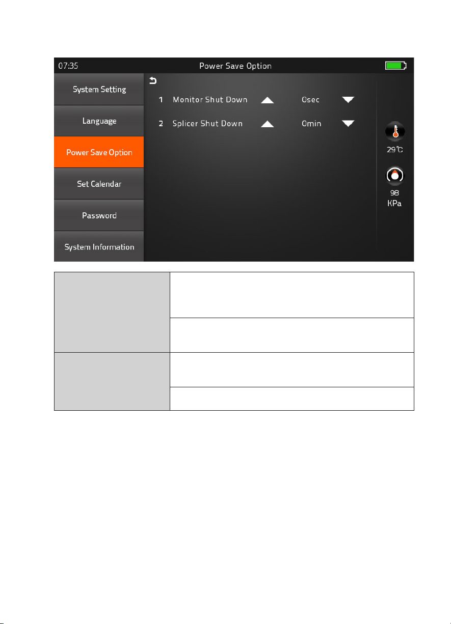
3) Power Save Option
Monitor Shut Down
1) No input during the time you set, the splicer will block
the power supply toward LCD
2) System will be switched over to standby mode.
Press the power button to resume
(Screen will be back on)
Splicer Shut Down
No input during the time you set,
the splicer will be shut down to save the power
Pressing the power button for 2sec, to reboot the splicer
- 22 -
Page 23
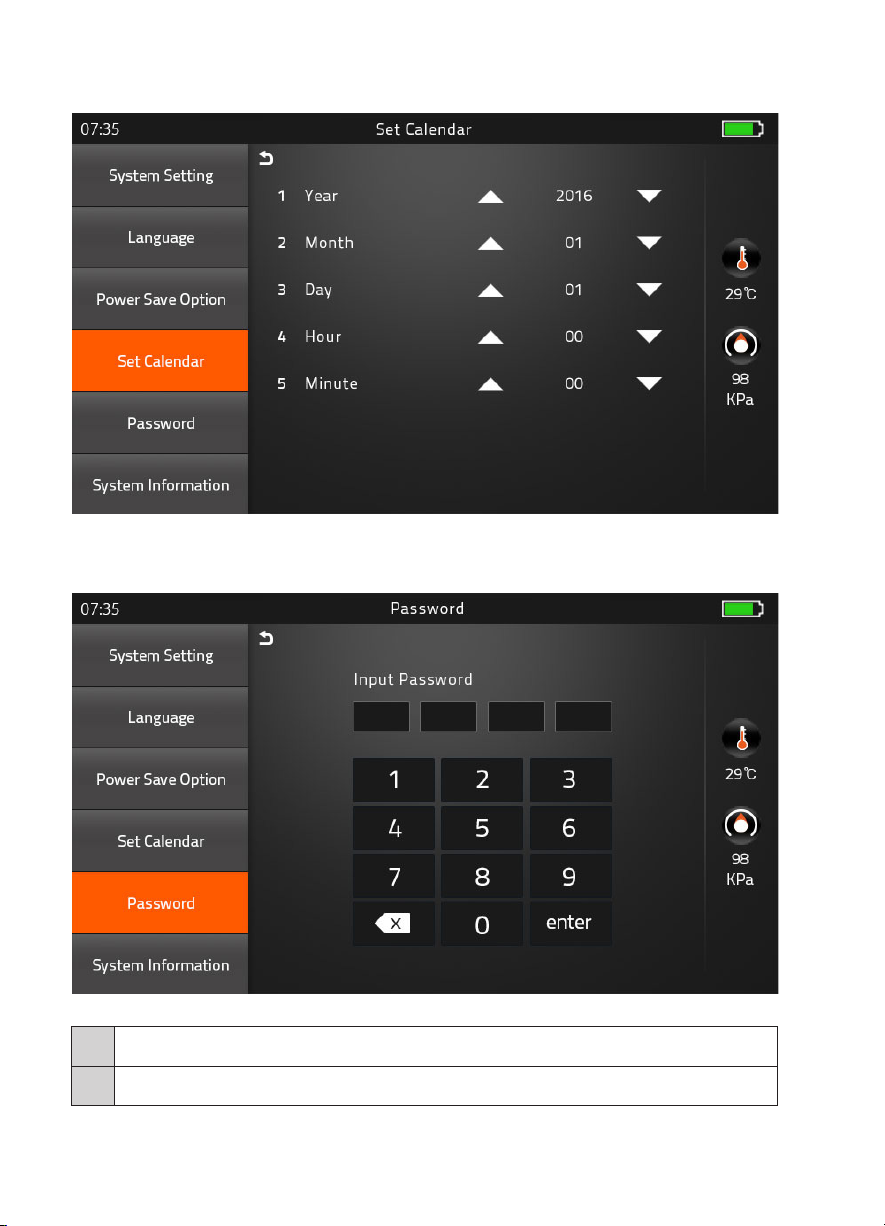
4) Set Calendar
5) Password
Change your password.
Procedure
1 Input 4-digit old password number
2 Input new 4-digit number for new password
- 23 -
Page 24
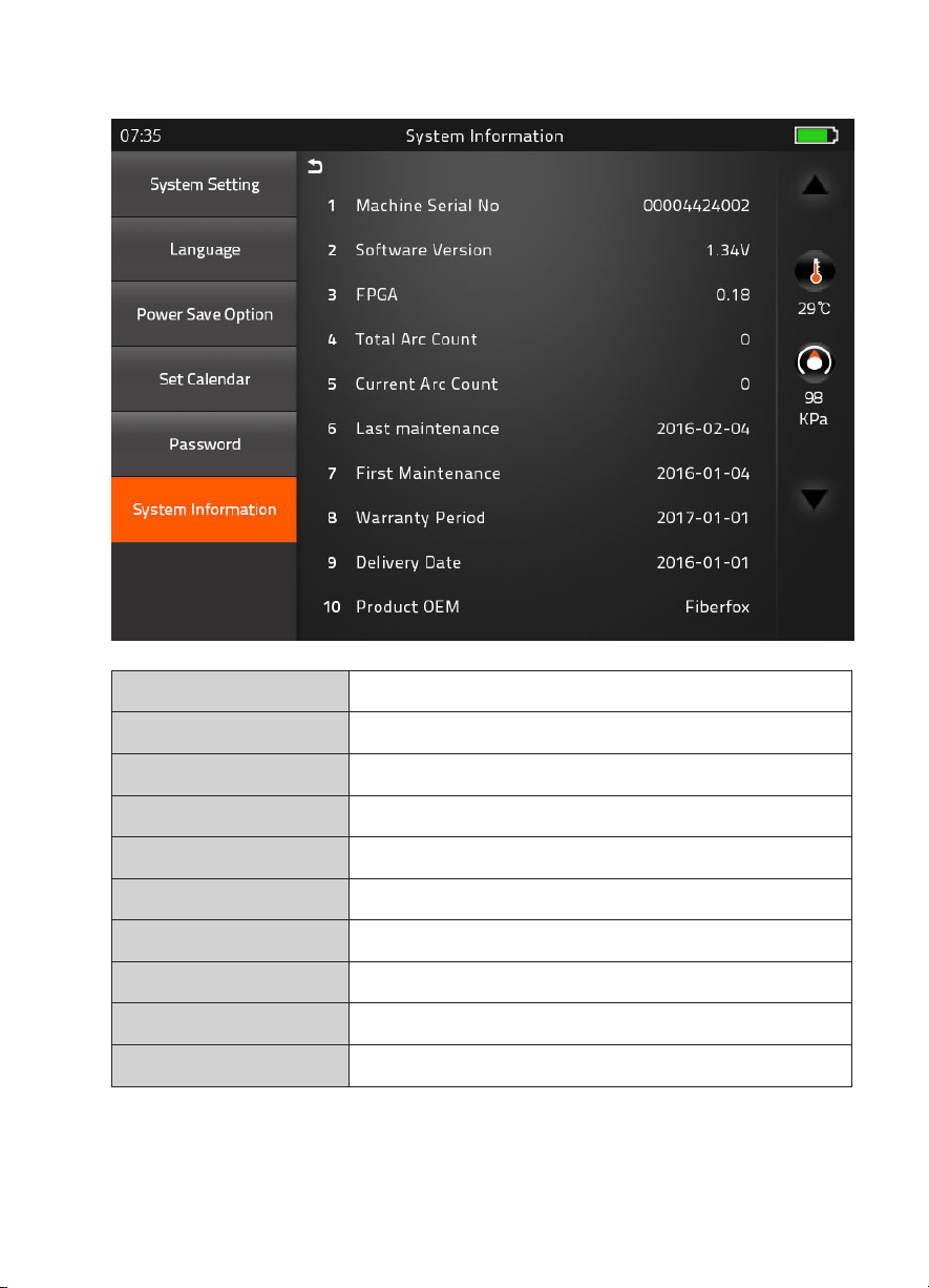
6) System Information
Machine Serial No. Identification number of the splicer
Software Version Software version being installed
FPGA Field programmable gate array’ version
Total Arc Count Total number of Arc discharges
Current Arc Count Current number of Arc discharge
Last Maintenance Last maintenance date
First Maintenance First manufacturing date
Warranty Period Warranty period
Delivery Date Delivery date
Product OEM Manufacturer name
- 24 -
Page 25
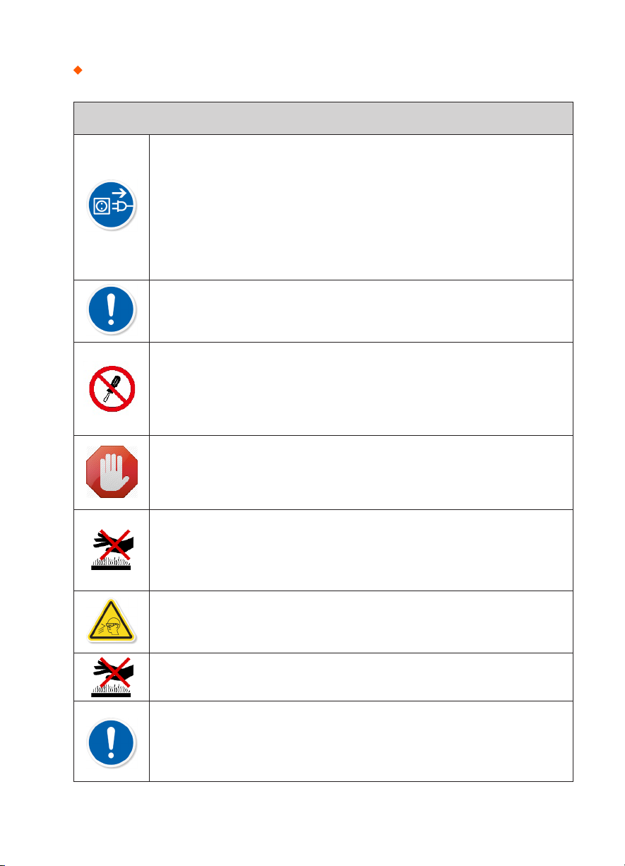
Notes: Warning and Cautions
Disconnect the AC/DC power cord from the wall socket(outlet) immediately
if user observes the following or if the splicer receives the following faults:
• Fumes, bad odor, noise, or over-heating occurs.
• Liquid or foreign matter falls into cabinet.
• Splicer is damaged or dropped.
If this occurs, ask our service center for repair.
Leaving the splicer in a damaged state may cause equipment failure,
electric shock or fire and may result in personal injury, death or fire.
Use only the AC/DC adapter / battery charger designed for this splicer.
Using an improper DC power source may cause fuming, electric shock or
equipment damage and may result in personal injury, death or fire.
Do not disassemble or modify the splicer, AC/DC adapter or battery.
In particular, do not remove or bypass any electrical or mechanical device
(e.g. a fuse or safety switch) incorporated into the design and
manufacturing of this equipment. Modification could cause damage that
may result in personal injury, death, electric shock or fire.
Never operate the splicer in an environment where flammable liquids or
vapors exist. Risk of dangerous fire or explosion could result from the
splicer’s electrical arc in such an environment.
It may result in personal injury, death, electric shock or fire.
Warnings!
Do not touch the electrodes when the splicer is on and power is supplied to
the unit. The electrodes generate high voltage and high temperatures that
may cause a severe shock or burn.
Note Arc discharge stops when wind protector is opened.
Safety glasses should always be worn during fiber preparation and splicing
operation. Fiber fragments can be extremely dangerous if it comes into
contact with the eye, skin, or is ingested.
Do not touch the splicer, AC/DC power cord and AC plugs with wet hands.
This may result in electric shock.
Do not operate splicer near hot objects, in hot temperature environments,
in dusty / humid atmospheres or when water-condensation is present on
the splicer. This may result in electric shock, splicer malfunction or poor
splicing performance.
- 25 -
Page 26
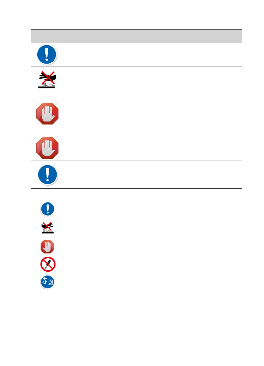
Warnings!
Do not store splicer in any area where temperature and humidity are
extremely high. Possible equipment failure may result.
Do not touch protection sleeve or tube-heater during heating or
immediately after completion of heating.
Their surfaces are very hot and touching these may result in burn.
The splicer is precision adjusted and aligned. Do not allow the unit to
receive a strong shock or impact. Possible equipment failure may result.
Use supplied carrying case for transportation and storage.
The carrying case protects the splicer from damage, moisture, vibration
and shock during storage and transportation.
Do not use any chemical other than pure alcohol (99% or greater) to clean
the objective lens, V-groove, mirror, LCD monitor, etc., of the splicer.
Otherwise blurring, discoloration, damage or deterioration may result.
The equipment must be repaired or adjusted by a qualified technician or
engineer. Incorrect repair may cause fire or electric shock.
Should any problems arise, please contact your nearest sales agency.
▶ Symbol means “Pay attention”.
▶ Pay attention to hot surface!
▶ Symbol means “Must do not”.
▶ You must not disassemble!
▶ You must disconnect a plug!
- 26 -
Page 27
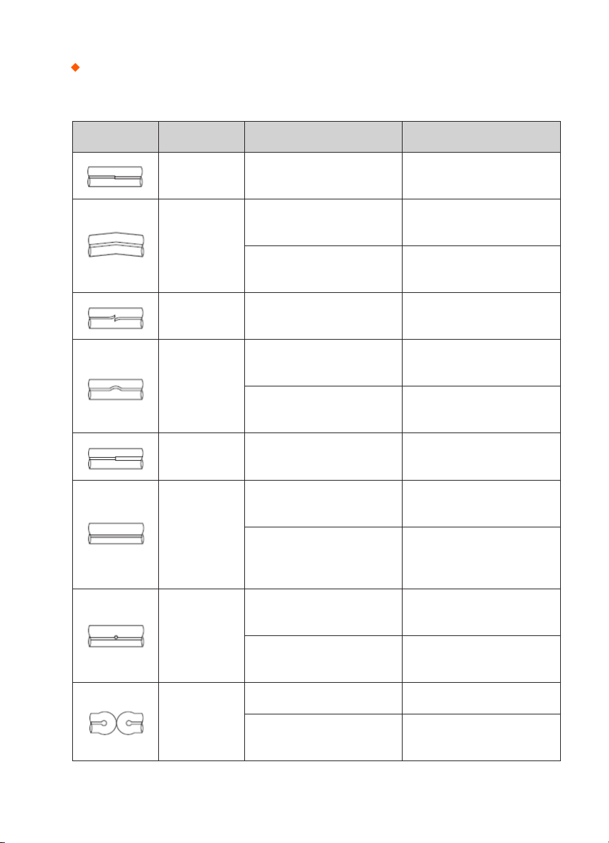
Appendix I
Splice loss increase : Reason and solution.
Symptom Name Reason Solution
Core Axial
Offset
Core Angle
Core Step
Core Curve
MFD
Mismatch
Combution
Dust on v-groove or fiber
clamp chip
Dust on v-groove or fiber
clamp chip
Bad fiber end-face quality
Dust on v-groove of fiber
clamp chip
Bad fiber end-face quality
Pre-fuse power too low or
pre-fuse time too short
Arc power too low Increase [Arc power]
Bad fiber end-face quality Check the cleaver
Dust still present after
cleaning fiber of cleaning
arc
Clean v-groove and fiber
clamp chip
Clean v-groove and fiber
clamp chip
Check if fiber cleaver is well
conditioned
Clean v-groove and fiber
clamp chip
Check if fiber cleaver is well
conditioned
Increase [Pre-fuse power]
and/or [Pre-fuse time]
Clean fiber throughly or increase [Cleaning arc time]
Bubbles
Separation
Bad fiber end-face quality
Pre-fuse power too low or
pre-fuse time too short
Fiber stuffing too small Perform [Motor calibration]
Pre-fuse power too high of
pre-fuse time too long
- 27 -
Check if fiber cleaver is well
conditioned
Pre-fuse power too low or
pre-fuse time too short
Decrease [Pre-fuse power]
and/or [Pre-fuse time]
Page 28

Fat Fiber stuffing too much
Arc power not adequate Perform [Arc calibration]
Decrease [Overlap] and
perform [Motor calibration]
Thin
Line
Note : A vertical line sometimes appears at the splice point when MM fibers, or dissimilar fibers (different diam-
eters) are spliced. This does not affect splice quality, such as splice loss or tensile strength.
Some arc parameters not
adequate
Some arc parameters not
adequate
Adjust [Prefuse power],
[Pre-fuse time] or [Overlap]
Adjust [Prefuse power],
[Pre-fuse time] or [Overlap]
- 28 -
Page 29

Appendix II
If error message is shown as below during the process, Please follow the instruction accordingly. If
the problem still remains, please contact us.
Error Message Reason Solution
L Fiber Place
Error
R Fiber Place
Error
Propulsion
Motor Overrun
Propulsion
Motor Trouble
Failed to Find
The Fiber
End-face
No Arc
Discharge
Motor Overrun
Cannot Find
the Edge of The
Cladding
Press the “Reset” Button. Reload
The fiber end-face is placed on the
electrode centerline, or beyond it
The fiber is no set correctly at the
bottom of the V-groove, which
results in that the fiber offsets
beyond motor formation range
Motor might be damaged Consult your nearest sales agency
The fiber is not set correctly at the
bottom of the V-groove
Arc Discharge does not occur
The fiber is not set correctly at the
bottom of the V-groove
The fiber is not set correctly at the
bottom of the V-groove
the fibers, make sure fiber end
face between V-groove and the
center position of electrodes
Press the “Reset” button and
then re-position the fiber at the
bottom of the V-groove
Press the “Reset” button and
then re-position the fiber correctly
at the bottom of the V-groove
Confirm the electrodes in proper
position; Replace electrodes
Press the “Reset” button and
then re-position the fiber at the
bottom of the V-groove
Press the “Reset” button and
then re-position the fiber at the
bottom of the V-groove
Find Wrong
Fiber Edges
Unidentified
Type of Fiber
There’s dust on the fiber surface
Shock occurred to the splicer
during the splicing process
- 29 -
Re-prepare the fiber;
Clean the lens and protector mir-
ror and then redo “Dust Check”
Execute “Motor Calibration” If the
[problem still exist, please contact
the sale agent]
Page 30

Unidentified
Type of Fibers
Shock occurred to the splicer
during the splicing process
Execute “Motor Calibration”
If the [problem still exist, please
contact the sale agent
Contact of Fiber
End-faces
Focus Motor
Overrun
Fibers
Mismatch
Large Cleave
Angle
Overlap too much Adjust overlap parameter
Motor is not calibrated Calibrate and maintain the motor
The fiber is misplaced
There’s dust of dirt on the fiber
surface
There’s dust of dirt on the fiber
surface
The fibers of two sides are
different type
Bad fiber end-face
[Cleave Limit] is set too low
Press the “Reset” Button and
then reposition the fiber correctly
Prepare the fiber again
Execute the [Dust check] after the
lenses and LEDs are cleaned
It may result in large splice loss if
you continue to splice,
Please use the proper splice mode
corresponding to the fibers
check the condition of the fiber
cleaver, if the blade is worn,
rotate the blade to a new position
or change a new one, and then
re-prepare the fibers
Increase the [Cleave limit] to an
adequate limit(standard:3.0˚c)
Large Core
Focus Error
Angle
[Core angle limit] is set too low
Dust of dirt is on the V-groove or
hte clamp chip
Too large axial offset(>0.4um)w Re-prepare the fibers
The motor is not calibrated Execute [Motor calibration]
- 30 -
Increase the [Core angle limit] to
an adequate limit (standard:1.0˚c)
Clean V-groove and clamp chip.
Prepare the fibers and re-load
them
Page 31

There’s dust or dirt on the fiber
surface
Prepare the fiber again
Dust Error
(fiber core)
Fat Fiber
The lens or LEDs are coated in
dust
Cleaning Arc time is too short
It is difficult to identify the fiber
core by using the method of core
alignment to splice
There’s dust or dirt on the fiber
surface
There’s dust or dirt on the fiber
surface
Execute the dust check after
cleaning the lenses and LEDs
Set the cleaning arc time to be
180ms
It is difficult to identify the fiber
core by using MM splice mode to
splice
Prepare the fiber again
Execute the [Dust check] after the
lenses and LEDs are cleaned
Increase the cleave angle limit to
Cleave angle limit is too low
a decent value
(standard value: 3.0˚c)
Overlap too much Adjust overlap parameter
Motor is not calibrated Calibrate and maintain the motor
Arc power too low Execute [Arc Calibration]
Thin Fiber
The level of pre-discharge is too
high
Decreased pre-discharge of
pre-discharge time
Insufficient overlap Adjust overlap parameter
- 31 -
Page 32

Appendix III
[Questions and troubleshooting]
· Power does not turn off when pressing On / Off button.
- Press and hold the key until the LED color changes from green to red.
· Few splices can be made with a fully charged battery pack
· If the power saving function is not enabled, battery power degrades quicker.
- [System setting] Always enable it to conserve power usage.
· If degradation appears (memory effect). of if the battery pack is stored for an extended period of
time, completely discharge it. After discharge completion, recharge the battery pack.
· The battery pack has reached the end of its service life. Install a new battery pack.
· The battery pack uses chemical reaction. The capacity decreases at low temperature, especially at
lower than 0 degree
·
Error message appears on monitor please refer to appendix II.
·
Inconsistent splice loss / High splice loss
·
Clean the V-grooves, fiber clamps, wind protector mirrors, and objective lenses.
·
Replace the electrodes.
·
Please refer to Appendix I.
·
The splice loss varies according to the cleave angle, arc conditions and fiber cleanliness.
·
Monitor suddenly turned off
·
The monitor suddenly turns off after an extended period of splicer inactivity, if the power
saving function is enabled. Press any key to return to the normal state.
·
Splicer power suddenly turned off without “Low battery’ message.
·
The monitor will turn off after an extended period of splicer inactivity, if the power saving
function is enabled. Press ant key to return to the normal state.
·
Identify fibers error in AUTO mode
- AUTO mode is applicable for SM, MM, NZ fiber. Errors may occurs while splicing special
fibers.
· Mismatch between Estimated splice loss and Actual splice loss
· The estimated loss is a calculated loss, so it can be used for reference only.
· The optical components of the splicer may need to be cleaned.
· Fiber protection sleeve does not shrink completely.
· Continue the heating time. [ 60mm Sleeve – 230 ˚c, 15sec, 40mm Sleeve - 200 ˚c , 17sec ]
· Extend the heating time.
· Method to cancer heating process.
˚c.
- 32 -
Page 33

· Press Heat key to stop during heating process. The LED light will go off after pressing.
· Fiber protection sleeve adhered to heating plate after shrinking use a cotton swab or a similar soft
tip object to push and remove the sleeve.
· Forgot password
- Please contact the sale agent or the Technical Support manager.
· No arc power change after [Arc calibration]
- An internal factor is calibrated and adjusted for the specific arc power selected.
The displayed arc power in each splice mode does not change.
· Forgot to lad fibers while execute some specified function that fibers are needed. Return key is
invalid. Open the wind protect shield, load prepared fibers in the splicer, and press “Set” to continue
or press “Reset”
· Upgrading Failure
- When users use the USB to upgrade, the splice may not be able to correctly identify the upgrade
file, you need to re-plug the HDMI cable with USB, and retry the upgrade software.
· Check if the upgrade file name and the format are correct.
· SDXX is for SD card Upgrade file, UpdateXX is for USB Upgrade file. The both zip file must be
extracted when you place on The USB.
· If you cannot solve the problem, please contact the Technical Support Manager.
· Other
- If you need more information, Please refer to the video in user’s CD.
- 33 -
 Loading...