

Fiberfab Jamaican 1976 Body Assembly Manual

THE
JAMAICAN
APPLICATION:
V-8
VW
Body
Assembly
manual
XNG
548
Baldwin
Street
Bridgeville, PA
1501
7
Phone
4 1 2-221 4200
COPYRIOHT
1876
n/&,rt
",,d
1
,,,."""+
~~n.,C"l.rr,,."r
.I
C
7-:L
-rr-l,.-,
".-.
-.-
-
p-.-.
"
"
FREE @ WWW.TJKUSTOMS.COM
Revised: Jan. 1974
INTRODUCTION TO
FIBERFAB'S JAMAICAN V8 and
VW
BODY KITS:
Early in 1968, the JAMAICAN body style was introduced as a completely
new model to supplement the famous Valkyrie and Avenger line.
The original JAMAICAN was designed as a direct replacement body for
several popular front-engined sports cars,
6.9. Austin-Healey, Triumph
and
MGA.
These replacement bodies are still currently in production.
Following the
JAMAICAN'S introduction, Fiberfab's engineering staff was
deluged with questions concerning the use of
V8 engines in the JAMAICAN
body style. To answer these questions, several installations wore de-
and tested,
e.g. the
JAMAICAN/MGA/BU~C~
V8 unit road tested by
TRACK magazine, March 1969.
Based on the interest shown in and performance of the hybrid
LIB'S,
Fiberfabls
engineers decided to build a "pure bred" JAMAICAN V8.
At
the outset, the project seemed simple
-
-
just build a frame to accept
a
V8 engine and that fits under a JAMAICAN body. However, the JAMAICAN
body was designed for a relatively short-wheelbase, narrow-track chassis.
A
no compromise V8 chassis would be too long and too wide for the ex-
isting body
-
thus started a six month development
of
a
brand new, wider,
tougher-looking JAMAICAN
V8 body and high performance chassis to match.
Shortly after the introduction of the JAMAICAN
V8 kit, requests for JAM-
AICAN adaptation to
VW
chassis started coming in. Seems as though people
are never satisfied, so
-
-
back to the drawing board.
An inner-liner was developed to use in the JAMAICAN
V8 body, so that
it
could be utilized on the
VW
"Bug" chassis with only minor modifications.
Since the wheelbase of the JAMAICAN
V8 and
VW
chassis are equal, the
adaptation was ideal.
Current production of the JAMAICAN series now includes the JAMAICAN
V8
body and frame kit; an identical JAMAICAN
\hI
body kits; similar body
styles for the TR3, TR4,
TR250, Austin-Healey 3000 and
MGA
chassis.
A
NOTE OF INTEREST:
A
Japanese import appeared on the American market in
1970. An immediate hit with the American people, the import bore a remarkable resemblance to our JAMAICAN series. Not surprising though, since
it
has been reported that a Fiberfab JAMAICAN V8 was in the possession of
the American importer of this car, some 18 months before the imported two
seater appeared on the American market.
FUTURE
PLANS
call for the development and introduction of JAMA1CA.N 11; a
body and frame kit using the
JAMAICAkI
V~/WW
body styling and a new frame,
utilizing complete Pinto drive-train components, rack and pinion steering
and all. An excellant "ECONOMY" car.
THANK YOU FOR YOUR INTEREST IN OUR PRODUCTS!!
The management
FIBERFAB, Inc.
FREE @ WWW.TJKUSTOMS.COM
Prior to mounting the main body section to the chassis/frame, cut out door openings,
as
well
as
Front and
rear
glass openings, as follows:
Cut
all
openings with sabre
saw:
1.
Using windshield glass a tmmplate, place
glasa in recessed
area,
center from top to bottom and side to side, using
small
blocks of wood
at
the bottom of glass to hold up in place.
Scribe or mark outline of glass and remove.
mark an additional line
1/2"
to
5/8"
inside the outline of the glass.
Cut on inner marking, leaving
a
lip
on which glass
will
rest
later
when installed with BUTYL TAPE (available from
all
local glass installers).
2.
Place
rear
qlaas in recessed arRa so that
qao
between glass and edge of body
are
equal all round. mark body nlonq edqe of glass and remove glass.
a.
If
using Porschn
rear
window
"H"
rubber to install glass, cut on mark.
b. If installing with
hutyl tape (as with windshield method) mark
as
section
line inside and follow instructions as above for windshield cutout.
c.
If undecided
~t
this
time,
cut
as
for windshi~ld type installation, as more
can be cut
later,
prior to installation.
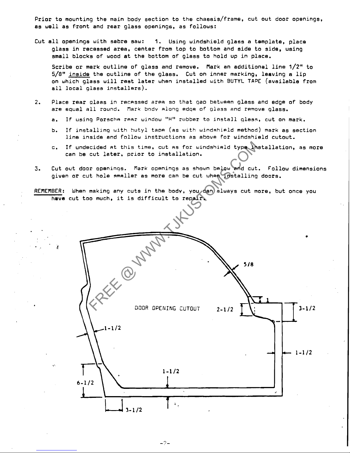
3.
Cut out door openinqs. Mark openings as shown bmlosl and cut. Follow dimensions
given or
cut hole
9msiller
as more can be cut when installing doors.
REflEflBER: When making any cuts in the body, you can always cut more, but once you
have cut too much,
it
is
difficult to repair.
FREE @ WWW.TJKUSTOMS.COM
1
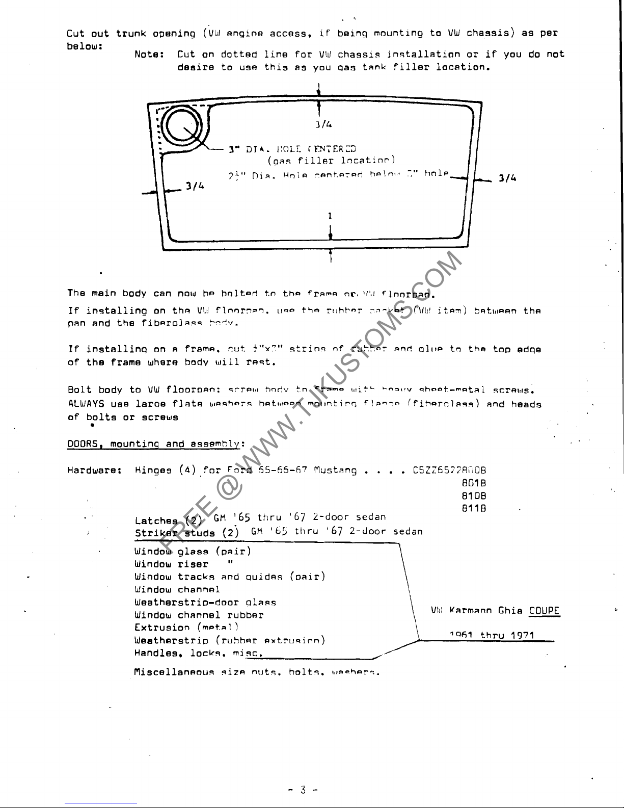
Cut out trunk opening
(VW engine access, if being mounting to
VW
chassis) as per
below:
Note: Cut on dotted line for
Vl~l
chassis ingtallation or
if
you do not
deaire to use this as you qas tank filler location.
4
I
3
/&
3"
Dl*.
/:OLE
IDTEAL3
(03s
filler lncatinr)
I
71"
Din.
Hola -ant.nrnr!
h~ln,,*
-,"
hnlp
c
3/&
1
1
I
t
b
The main body can now he holtarl
t.n
thn
fram~
nr,
rrl,~
rlnnr~an.
If
installing on thn V\II
flnnrrt~?.
~rqo
~LIQ
ft~hb-~
:fi-b~t
(\/\I'
itnnj bFit\lrA~n thcl
pan end the fib~rolaqs
?--!v.
If
installinq on A fram~. cut.
!"Y?'
strinn
of
rzkkor
ant!
Q~IIP
tn
tha top edqe
of the frame where body
will
rnst.
Bolt body to
VW
flooronn: srrnl,r
hodv tn cr3mo
c,titc
Coarqv
shoot.-matai scrnlllg.
ALWAYS
use larQ8 flate
blnnhers
h~tc~taom
mnt1ntir.n r!a--o (fihar?las5) and heeds
of bolts or screws
w
DOORS, mountinq and assemkly:
.
Hardware: Hinges
(4)
for
Ford
55-66-67
Mustang
. . . .
CSZZ65;7RClOB
801 B
Bl
OB
Latches
(2)
GM
'65
thru
'67
2-door sedan
,
.
J
Striker studs
(2j
GM
'65
thru
'67
2-door sedan
.
-
Window glass (pair)
Window riser
"
Window tracks and ~uid~s (oair)
Window channel
\
Weatherstrio-door plaqs
Window channel rubber
\
Vlrl
Uarmann Ghia
COUPE
Extrusion
(m-t.al
)
Weetherstri~ (ruhhnr cl~trusinn)
Handles, lock5. mi3c.
fliscellansous giza
n~tq.
holtl. ~,larharq.
FREE @ WWW.TJKUSTOMS.COM
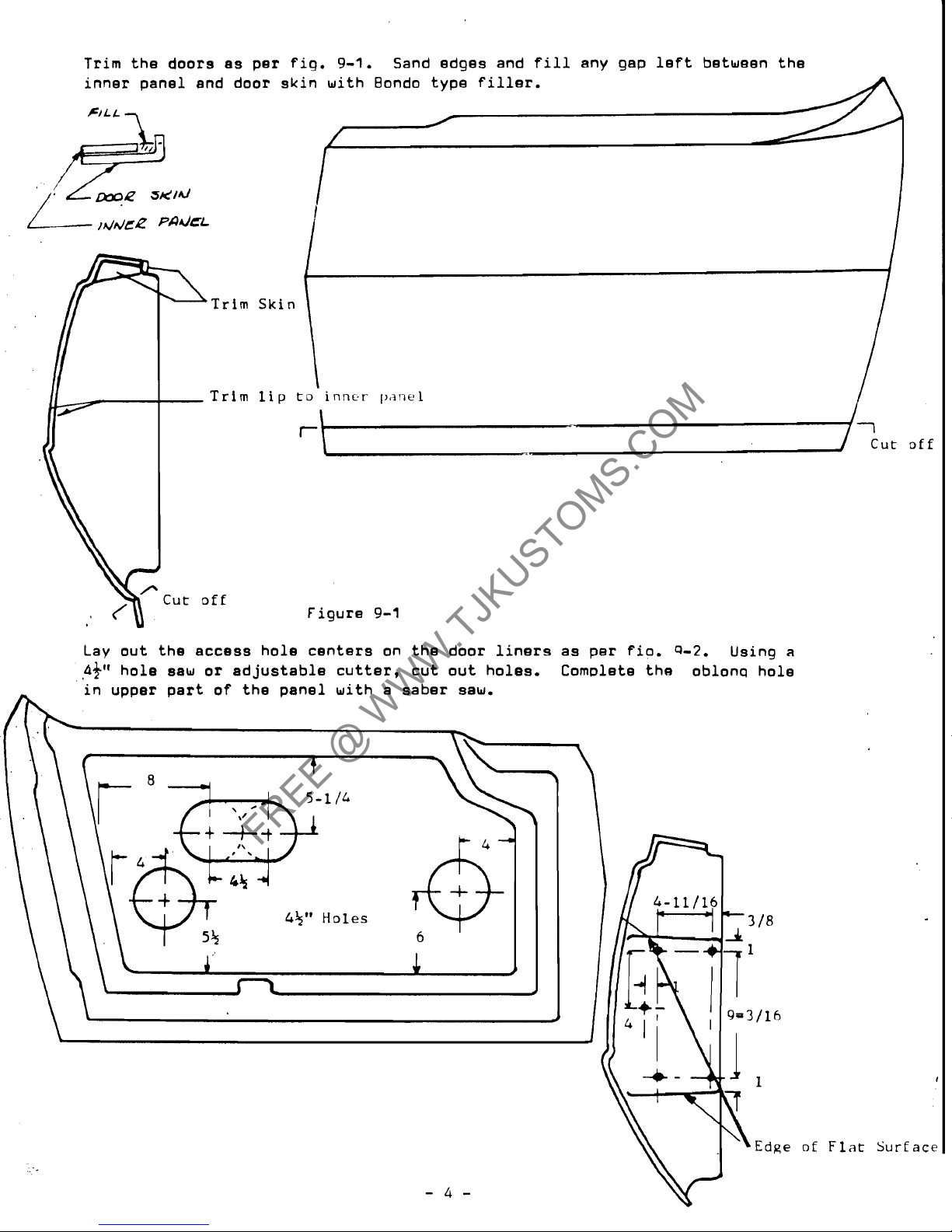
off
Lay out the access hole centers on the door liners as per
fio.
9-2.
Using
a
43"
hole saw or adjustable cutter, cut out holes. Cornolete the oblon~ hole
in upper part of the panel with a saber saw.
I
Surf
ace
FREE @ WWW.TJKUSTOMS.COM
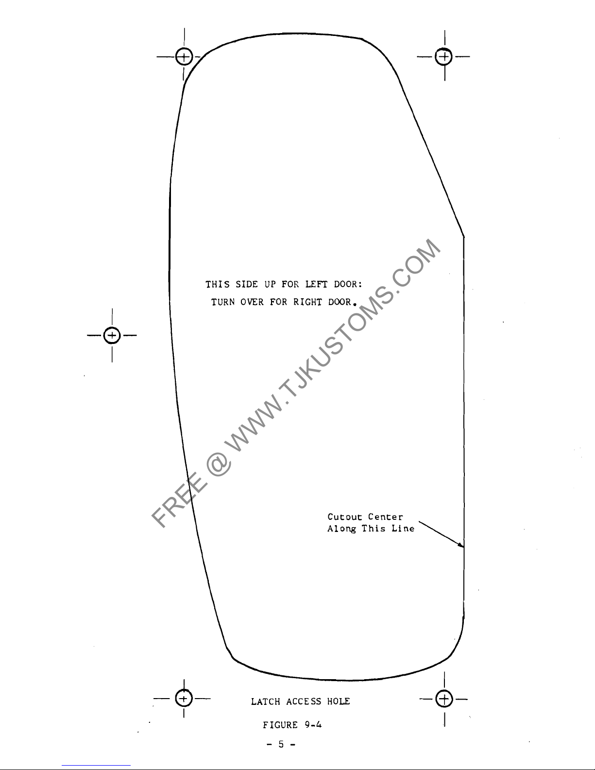
THIS SIDE UP FOR
LEFT
DOOR:
TURN OVER FOR RIGHT DOOR.
Cutout Center
Along This Line
LATCH ACCESS HOLE
-0-
I
FIGURE
9-4
I
FREE @ WWW.TJKUSTOMS.COM
112
1
J
\
1
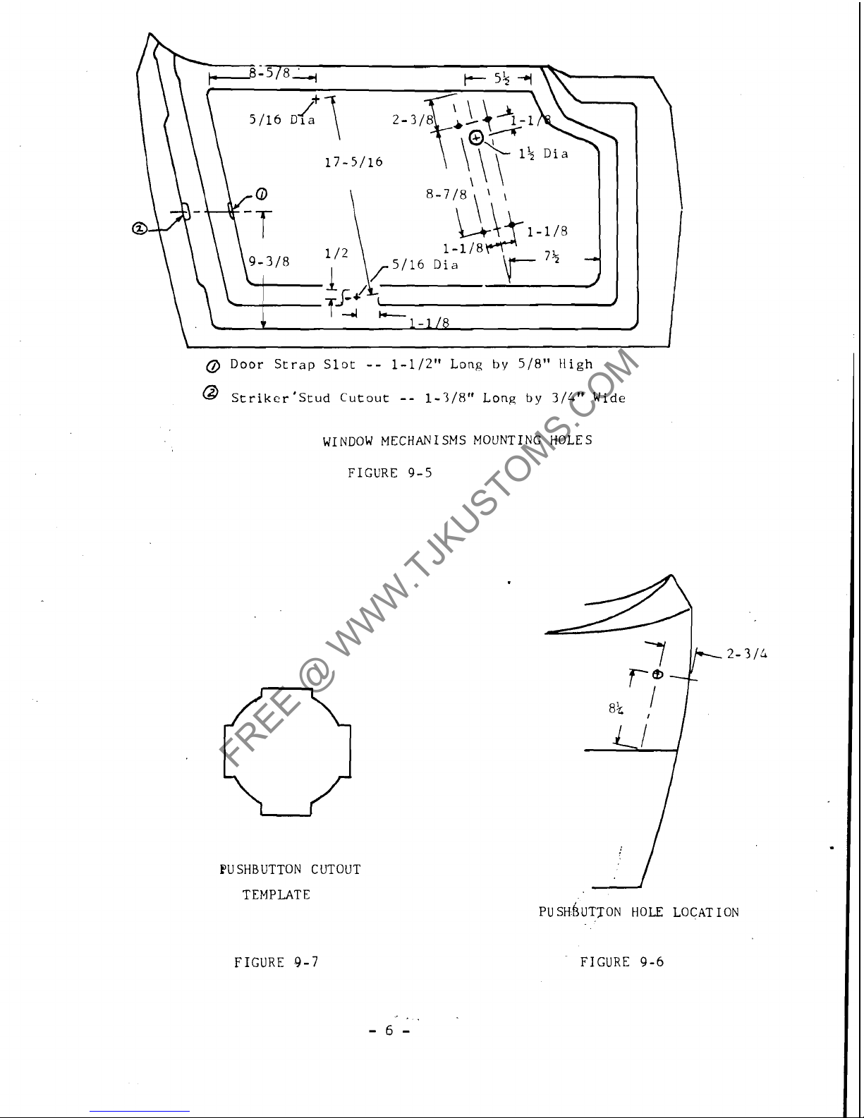
Door Strap Slot
--
1-112" Long
by
518"
High
@
striker8Stud Cutout
--
1-318" Long
by
3/4" Wide
WINDOW MECHANISMS MOUNTING HOLES
FIGURE 9-5
PU
SHBUTTON CUTOUT
TEMPLATE
FIGURE
9-7
FIGURE 9-6
FREE @ WWW.TJKUSTOMS.COM
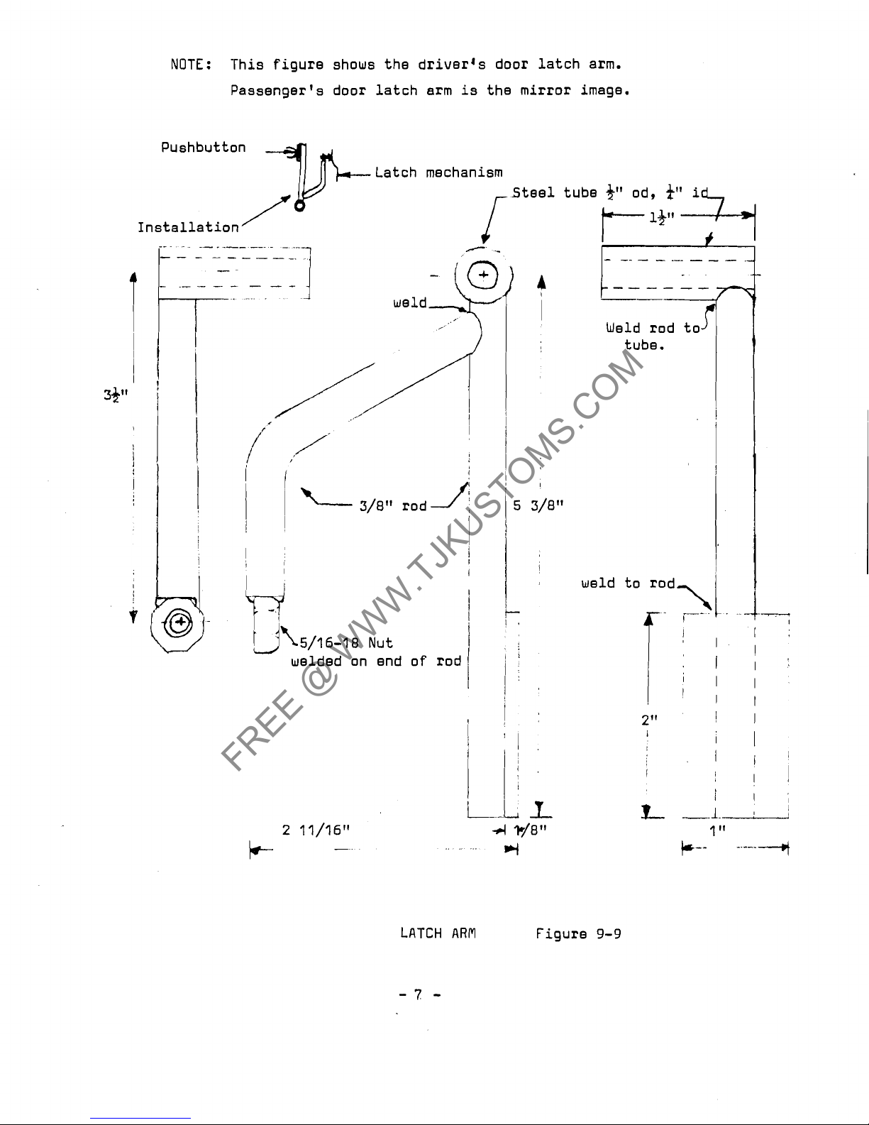
NOTE: This figure shows the driver's door latch arm.
Passenger's door latch arm is the mirror image.
Pushbutton
Latch mechanism
Steel tube
3''
od,
a"
i
Installation
---
--
-
- - -
- - - - -
.-
-.
-
-------
--
Weld rod to
I
!
tube.
33"
1
I
I
1
I
i
IT
5/16-18 Nut
welded on end of rod
I
2"
!
I
I
I
I
i
I
iI
.I
1'
I
i.L
1
1
;
L
1.
1
LATCH ARM
-7
-
Figure
9-9
FREE @ WWW.TJKUSTOMS.COM
Cut door latch holes: Lay out the five hole8 in the rear face of each door as
specified in fig.
9-3 and drill with bit.
Now take template, fig.
9-4 and cut out the five locating holes and the center
as
illustrated. Align template on the door using the five holes for locetion and
scribe the center cut-out
-
-
cut out the latch holes with a sabre saw.
Lay out
the striker stud cut-out and door strap holes as per fig. 9-5 and cut-out.
Cut holee for puah buttons (obtain buttons from Chrysler product truck lid, early
50's)
as
per fig. 9-6. Next, cut out the template, fig. 9-7, locate on door and scribe.
Cut out the round portion of the shape and file out remainder.
Note:
If
you are going to use handlee in lieu of the buttons, the hole
will
be in
the same location but of a different shape.
Drill
holes to Locate
window
mechanisms, fig.
9-5
Fabricate latch plate (2) as per fig.
9-8.
Use
14 gauge steel plate or 1/1611
approximately.
Bolt latches to plates.
Be
sure the notch in the plate lines up with the striker
stud catch in the latch.
Now, bolt plate (with
latoh) to the doors.
Fabricate latch arms
as
per fig. 9-9. These arms are required to transmit the
push button action to the latch mechanism.
Install in the door using
$'I-20x2" oval head bolt through the remaining hole
next
to
the latch plate, mounting the
arm
on the bolt (inside the door)
as
per
fig.
9-9.
Secure with
)-20
self
lock
nut.
Do not over-tighten so that the arm
is
no longer free to rotate.
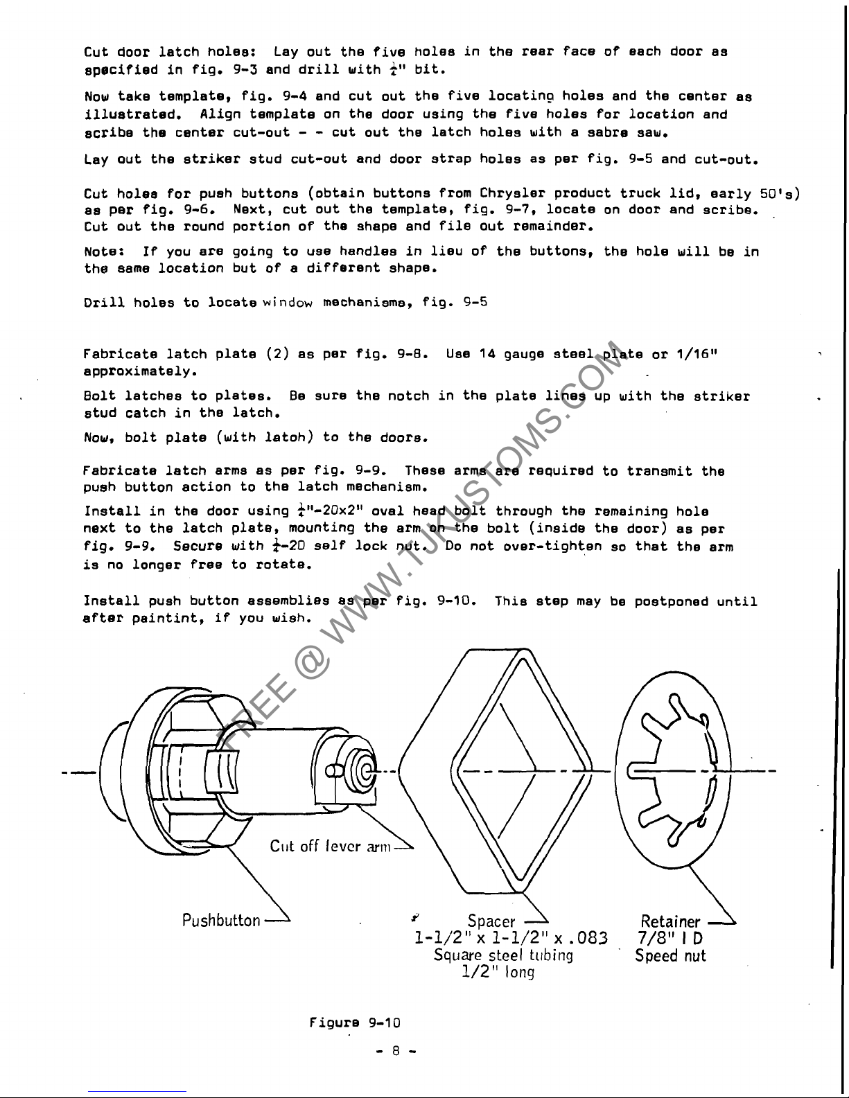
Install push button assemblies
as
per fig. 9-10. This step may be postponed until
after paintint, if you wish.
Pushbutton
J
Spacer
1
1-1/2" x 1-1/2"
x
.083
Square
steel tubing
1/2"
long
Figure 9-10
-8-
Retainer
7/8"
l
D
Speed
nut
FREE @ WWW.TJKUSTOMS.COM
 Loading...