

Page 1

Page 2
Page 3

Table of Contents
Construction Material, Tools and Power Tools
Selecting a VW To Use For Your Aztec 7
Removing The VW Body
Disassembling The VW
Chassis Preparation
Softening Front Suspension
Decambering Rear Suspension
Installing Tail Section Supports
Installing Heater Vent Tubing
Mounting The Voltage Regulator
Installing Gauge Sending Units
Installing The Center Console
Installation of Spedometer Cable
Main Body Preparation
Cutting the Windshield Opening
Cutting the Rear Window Opening
Cutting the Door Openings
Defroster Installation
Windshield Wiper Motor Installation
Drill Holes for Wiring Harness
Preparation of Dash and Overhead Console
Installation of Gauges and Switches
Installation of Dashboard
Routing the Main Body Wiring
Installing the Main Body on the Floor Pan
The Gull-Wing Doors
Preparing the Gull-Wing Doors
Cutting the Side Window Openings
Preparing the Door for Latches
Locating the Door Hinges
Mounting the Door Hinges
Installing the Door Assist Cylinders
Installing the Door Latches
Fitting the Striker Plates
Installing the Door Stops
Preparing the Door for the Installation of Side Glass
Installing the Side Windows
Installing the Headlight Dimmer Switch
Detailing the Interior
Installing Headliner
Installing the Rear Firewall Upholstery
Installing Upholstery on Front Firewall
Installing Side Panels
Installing Door Flange Trim
Upholstering Center Console
Installing Shifter Boot
Installing Floor Mats
Installing Door Panels
Installing Heater Vents
Installing Overhead Console
Installing Steering Shaft
Installing the Steering Wheel
Installing Side Glass Weather-strip
Installing Rear Glass
Installing Windshield
Installing the Seats
Tail Section
Installing Rear Bumper
Installing License Plate Lights
Weather Stripping
Page 4

The Nose Section
Assembling the Headlight Boxes
Installing the Headlight Units
Installing the Front Bumper
Fastening the Nose to the Main Body
Installing the Nose Supports
Wiring the Front of the Car
Installing the Brake Fluid Reservoir
Installing the Hood
Installing Locking Hood Hold-down Pins
Gas Tank Installation
Painting
Mirrors and Trim
Bolt Descriptions
Bolt Kit Listing
Wiring Harness
Templates
Rear Glass Opening
Driver’s Side Template for Veneer
Passenger’s Side Template for Veneer
Overhead Console Switch Holes
Page 5

CONSTRUCTION MATERIAL, TOOLS AND POWER TOOLS
Essential Hand Tools 1. Complete Socket Sets-both Metric and Standard
2. Screwdrivers-both Standard and Phillips
3. Straight – Edge
4. Tape Measure
Helpful Hand Tools 1. Open End and/or Box Wrenches
2. Pop Rivet Gun, Various Size Rivets
3. Wire Terminal Crimping Tool
4. Hacksaw
5. Set of Wood Working Hole Saws or Adjustable Hole Cutter
Essential Power Tools 1. Electric Drill
2. Jigsaw
Helpful Power Tools 1. Rotary Sander/Grinder
2. Hydraulic Floor Jack and Jack Stands
Essential Construction
Materials 1. Assorted Sheet Metal Screws
2. 40, 120, 240 and 400 grit Sandpaper
3. Electrical Tape
4. Silicone Seal
Helpful Construction
Materials 1. Epoxy Adhesive Kit
2. Epoxy Putty/Filler
3. VW Service Manual
SELECTING A VW TO USE FOR YOUR AZTEC 7
First, the variants (Fastbacks and Square backs) and Super Beetle series are not suitable.
When buying a VW to use with your Aztec 7 kit, remember the necessities are the floor pan, complete front end,
transaxle and engine. If these parts are complete and not damaged, the car is useable. Don’t be fooled by a bent-up
rusted body.
The following inspection checklist can be used as a guide to aid you in choosing a chassis/engine system:
1. Floor pan – check for bent flanges, rust, cracks and dents
2. Front End – check for collision damage, bent tie rods, worn ball joints, bent shock towers, worn steering gear and
bearings.
3. Transaxle – check for proper clutch operation and smooth shifting; listen for noise from gears and universal joints
while rolling the car forward; inspect trans case for leaks and metal chips in oil.
4. Brake System – check for scored brake drums, leaky wheel cylinders, spongy pedal.
5. Engine – inspect engine oil for leaks, low compression and smoking exhaust.
Description of Model Year, Engine and Chassis
1961-1965
Engine 1200CC-40 hp
All Synchromesh transmission
Swing arm rear suspension, link pin front suspension
1966
Hp increased to 50 hp
Ball joint font suspension
1967
Engine 1500cc-53 hp
12 volt electrical system
Page 6

Dual brake system
Two speed windshield wipers
1968
Auto stick shift
4 bolt wheel pattern
1969-1970
Engine 1600cc – 57 hp
Swing axel replaced by CV joints
Steering column and ignition lock
1971
63 hp
1972-1973
VW diagnostic system installed
1975-1977
Electronic Fuel Injection
Alternator with integral regulator
REMOVING THE VW BODY
Tools Necessary Metric wrenches and sockets – 16mm to 19mm
1-1/8 inch socket
Standard and Philips Screwdrivers
Hammer
Cold Chisel
Penetrating Oil
VW Service Manual
Parts to Save From VW Body
Chassis, engine, transaxle and front end
Complete Steering Column and hardware
Voltage Regulator
Gas Tank and Gas Tank Mounting Clips
Battery
Brake Fluid Reservoir and Hoses
Headlight Dimmer Relay
All Body Mounting Bolts and Body Washers
DISSASSEMBLING THE VW
1. Remove the front and rear seats
2. Remove the battery (save brackets)
3. Remove voltage regulator
4. Remove the four bolts from the rear body mounting flange (save)
5. Remove the bolt from each side under the rear seat back cushion
6. Remove the seat belts
7. Disconnect the speedometer cable from the left front wheel
8. Pull the speedo cable through the hub by pulling it from the inside of the spindle.
9. Remove the cardboard covers over the dash and gas tank in the luggage compartment.
10. Locate and remove the headlight dimmer relay and save
11. Remove the speedometer cable by disconnecting the cable from the speedometer and pulling the cable out of the
body.
12. Drain the fuel tank
13. Remove the four gas tank brackets and bolts. (save the brackets)
14. Disconnect filler hose from the tank. (’68 and later)
15. Remove the fuel tank and set aside for use later
16. Remove the brake reservoir complete with metal hoses. Leave the flexible rubber connecting hoses on the master
cylinder. Two 5/16 inch bolts will work well.
Page 7

17. Disconnect the wires from the brake master cylinder switches
18. Identify the wires into the passenger compartment through the hole in the dash under the steering column
19. Pull these wires into the passenger compartment through the hole in the dash under the steering column.
20. Remove the horn ring cover with a small screwdriver
21. Disconnect the ground wire at the horn ring.
22. Remove the steering wheel nut and spring washer.
23. Remove the steering wheel with horn ring.
24. Remove the turn signal canceling cam from the bottom of the steering wheel and save it.
25. Remove and save the retaining circlip from the steering column
26. Remove the bolts that secure the steering column bracket to the dash.
27. Pull the steering column housing off the steering column shaft. Also remove and save the rubber grommet at the
base of the housing.
(NOTE: If vehicle was equipped with a locking steering column, the ignition key must be switched "on"
before the housing can be removed.)
28. To remove the steering column shaft: unbolt the steering shaft from the steering box at the flexible coupling. Save
the bolts and nuts for use later. Push the steering shaft toward the passenger compartment. When the flexible
shaft is free from the steering box, pull the shaft up and forward, out of the body.
29. Remove the bolts that secure the body to the front torsion tubes beneath the area occupied by the gas tank. Save
these bolts.
30. Raise the rear of the car and remove the rear wheels. Rear body mounting bolts will be found just forward of the
shock absorber mounts. Remove these bolts. Make certain the car is securely supported as considerable force
may be necessary to remove these bolts.
31. Remove the flexible tubes between the heat exchangers and the body.
32. On newer models, remove the rear equalizer spring (stabilizer bar).
33. Replace the wheels and lower the car to the ground.
34. Disconnect the wiring from the main harness to the engine. These wires will be:
a. From the oil pressure sender located just below the distributor
b. Two wires on the generator
c. The wires on the starter motor
d. The wire from the main harness to the coil.
35. Working under the car with the car on the ground, remove all body bolts. Save the "U" shaped washers.
Removing the Body
Before trying to lift off 'the body, make certain the following steps have been performed.
1. All body bolts removed.
2. Steering column disconnected and removed.
3. Engine and brake wiring removed.
4. Heater hoses removed.
5. Rear stabilizer bar removed (newer models).
The body can now be lifted off with a block and tackle or several strong friends. Lift the body to the side of the
chassis, not over the front or rear.
Page 8

CHASSIS PREPARATION
Refer to Figure 4
1. Now is the time to repair or replace worn engine, chassis, transmission, and suspension components because
they will be easily accessible.
2. Remove battery brackets from the floor pan with a cold chisel.
3. Chisel off the two back seat heater cable tubes.
4. Using a hacksaw, saw off the jacking sockets flush with the edge of the floor pan flanges.
5. Use a cold steel chisel again to remove the seat rails on both sides of the pan.
6. Repair any floor pan damage using fiberglass cloth and resin. On small holes use silicone sealant. These
materials are available at most auto supply stores.
7. Clean the entire chassis. This can be done at home with engine degreaser or by professional steam cleaning.
Steam cleaning is advisable.
8. After chassis has completely dried, remove all rust, using a wire brush.
9. Paint the entire chassis with a good rust preventive paint.
Page 9
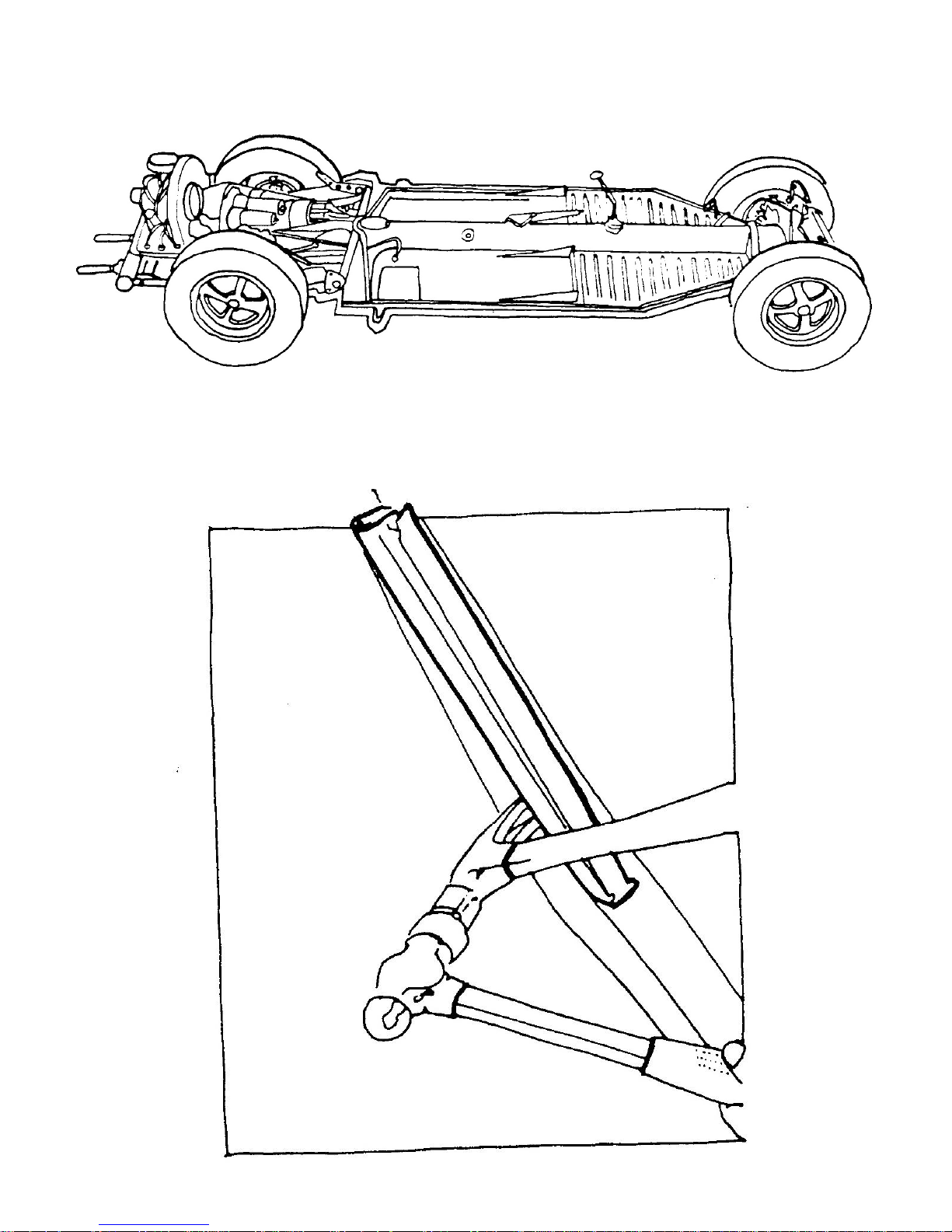
Figure 4a VW Chassis
Figure 4b Removing Seat Rail
Page 10
SOFTENING FRONT SUSPENSION
Because the Aztec 7 fiberglass body is lighter than the Volkswagen body, the front suspension must be modified or
"softened," to compensate for the weight reduction.
Tools Required Wrenches
Screwdrivers
Scribe
Welding torch -Optional
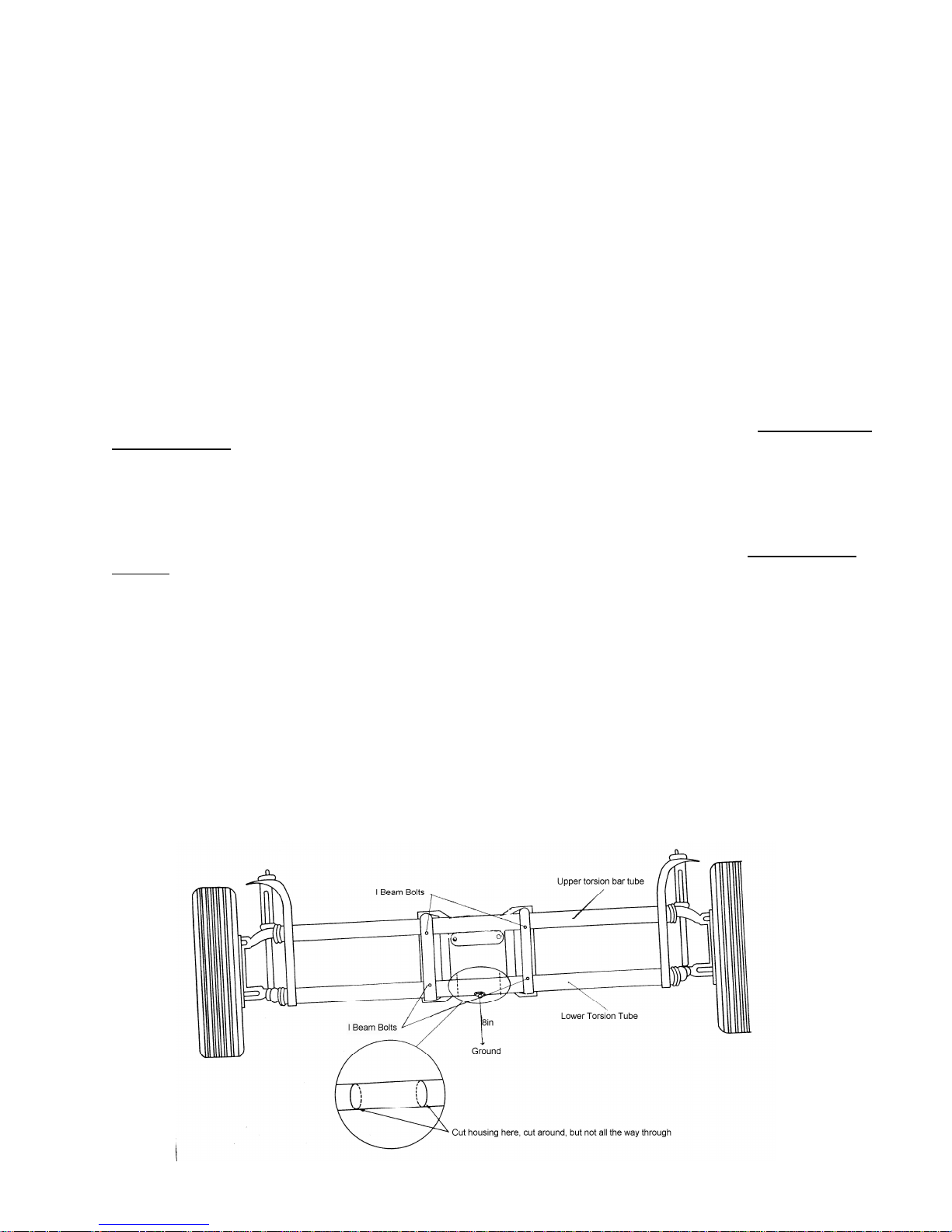
Refer to Figure 5a and Figure 5b
1. Place the front of the chassis on jack stands.
2. Disconnect the brake lines on each side of the l-beam, by removing the holding clips and unscrewing the
connecting lines.
3. Disconnect the front suspension from the chassis, by removing the four bolts on the l-beams.
4. Scribe two lines around the lower torsion bar tube housing, 2" to the right and 2" to the left of the center bolt on
the tube. .
5. Using a pipe cutter, cut around the torsion bar tube housing, along the lines scribed in Step 5. Cut only through
the tube housing do not cut the torsion bars enclosed within the housing.
6. Re-install the front end on the chassis. Do not re-connect the brake lines and steering damper at this time if you
plan to do your own welding. When the procedure is complete, the 4" cut portion of the housing (with the center
bolt) should move freely from the remainder of the housing when weight is applied.
7. Place approximately 175 lbs. of weight on the front of the I-beam. (A person standing on the l-beam will
accomplish this.) With the proper weight applied, the lower torsion bar should be 8" from the ground.
8. Tack weld the center portion of the tube housing back to the sides of the tube housing in the same, weighted
position obtained in Step 7. (NOTE: All welding can be done when the car is totally assembled. The car can
be driven to a gas station for welding.)
9. Remove the I-beam from the chassis and permanently weld the center of the torsion bar tube housing to the side
housing.
10. Re-install the I-beam onto the chassis. Reconnect the brake lines using the original clips, etc.
NOTE: Step #8 to be done with tires to be used on chassis.
NOTE: Stock VW shocks are recommended. The height can be reduced by cutting the rubber stops at the top of shocks
in half.
Figure 5A Front Suspension
Page 11
DECAMBERING REAR SUSPENSION
Tools Required Jack Stands
Wrenches
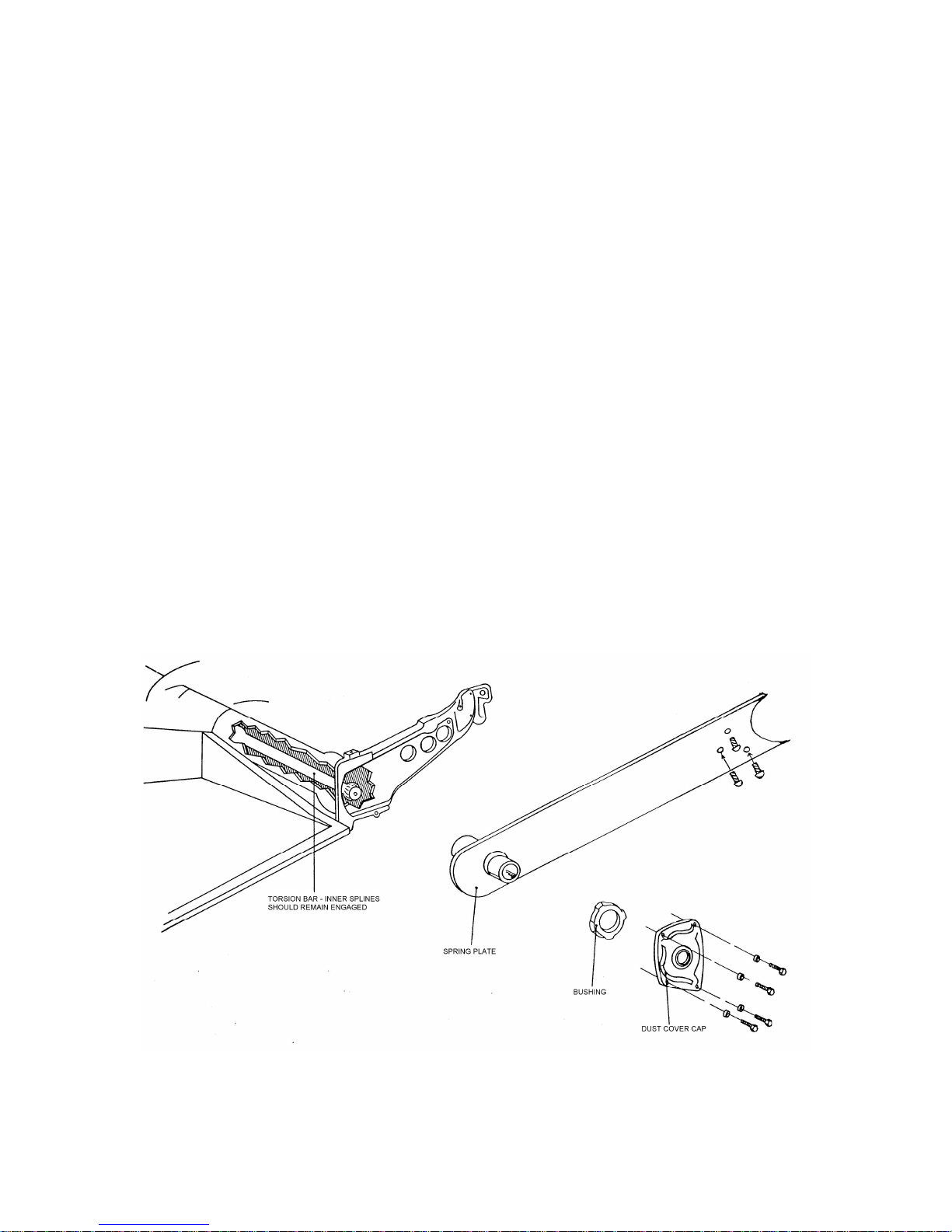
Refer to Figure 5a and Figure 5b
1. Place the rear wheels of the VW chassis on jack stands or blocks, and remove the rear wheels.
2. Unbolt the four bolts that hold the torsion bar dust cover cap, and the three bolts that hold the spring plate to the
rear axle.
3. Remove the dust cover and rubber bushing covering the torsion bar and spring plate splined edges as shown in
Figure 5.
4. Scribe a line across the surface of the spring plate and torsion bar splines to establish a reference point.
5. Once the reference point is established, pull the spring plate off of the torsion bar, being careful not to pull the
inner torsion bar splines (in the center of the torsion tube) rot. At the same time disengage the spring plate from
the rear axles. The rear axles will spring rearward out of the spring plate.
(NOTE: Spring plates are under tension when they disengage from the rear axle, keep hands
clear.)
6. Once the spring plate is disengaged, rotate the spring plate one notch counter clockwise on the driver side, and
clockwise on the passenger side. The reference point marked above will indicate one notch moved.
7. Re-engage the spring plate at this point on the torsion bar and rear axle in the spring plate. Bolt the spring plate in
place at the rear axle with the three bolts from the original assembly.
8. Replace the rubber bushing and bolt the dust cover cap into place, using the bolts from the original assembly.
9. The decambering is now complete. To check the suspension, have someone weighing between 160 and 185
pounds stand on the chassis, near the rear torsion bars. Ron the chassis back and forth. The rear wheels should
be almost vertical.
(NOTE: On models using Constant Velocity Joints (CVJ) decambering of the rear suspension may not be
necessary (1969 models and up).
Figure 5B Decambering the Rear Suspension
Page 12
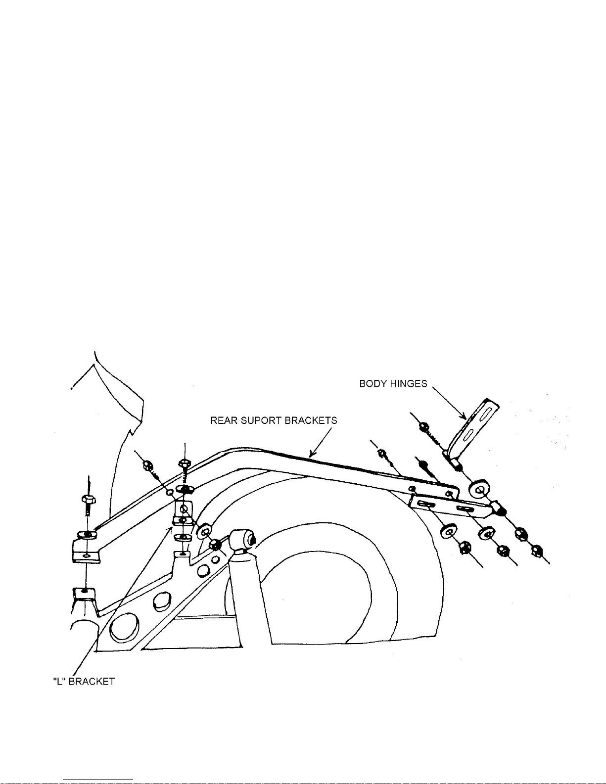
INSTALLING TAIL SECTION SUPPORTS
Tools Required 2 - 9/16 inch wrenches or socket set
2 - ¾ inch wrenches or socket set
Parts Requires Ff #Z763 1 set rear body supports and #Z762 hinges
Ff #X137 chassis paint
Ff #1 bolt pack
Refer to Figure 6
Install rear tail section supports to chassis. The illustration below shows both hangers in place on the mounts
formerly used to secure the VW body. When the tail section is installed, shims (washers) may have to be placed under the
front, rear or both hanger mounting feet, to precisely align the tail section with the main body. Make certain the movable
end plates are extended to the very end and the pivots are positioned downward. A diagram of the installation is shown in
Figure 6.
Figure 6 Tail Section Supports
Page 13
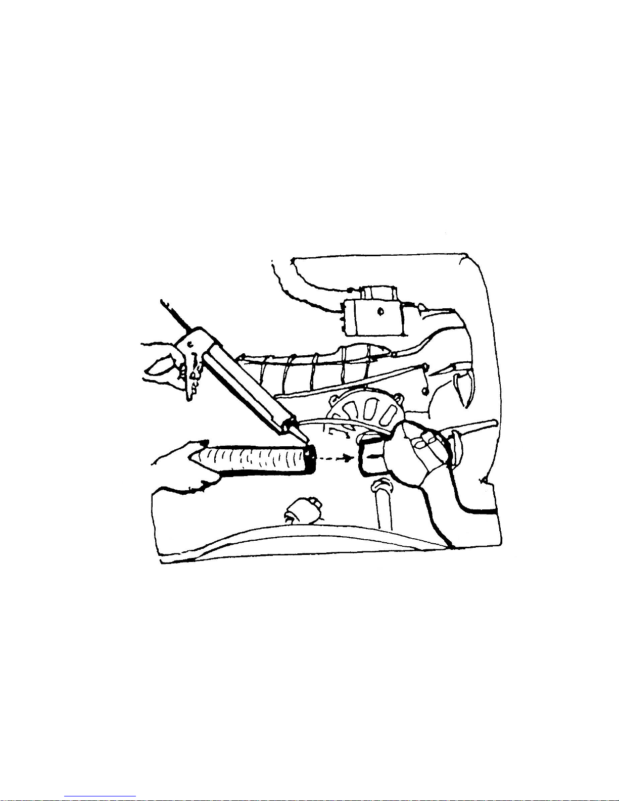
INSTALLING HEATER VENT TUBING
Tools Required Knife
Caulking Gun
Parts Required Ff #X180 heater tubing
Ff #MX193 Silicone
Refer to Figure 7
Cut two lengths of heater tubing 24 inches long each. Apply a bead of silicone all the way around the tube
approximately 1 inch from the end as illustrated in Figure 7. Install heater tube in the heat exchanger on the engine. Seal
this joint with silicone.
Figure 7 Installing Heater Vent Tubing
Page 14
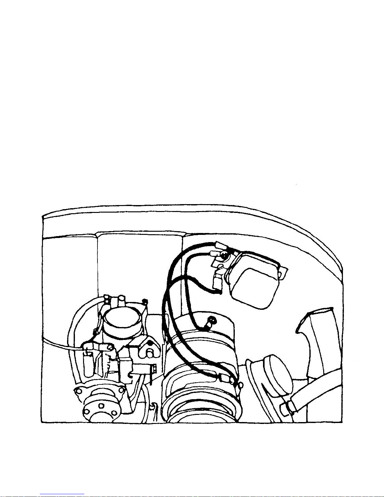
MOUNTING THE VOLTAGE REGULATOR
Tools Required Electric Drill and Drill Bits
Screwdriver
Wire Cutter/Stripper
Parts Required 14 Gauge Wire
12 Gauge Wire
Wire Terminals
#10 X ½ inch Metal Screws
Refer to Figure 9
Locate the regulator on the fan shroud directly above the generator/alternator flange. Mark and drill two holes and
fasten the regulator to the shroud using #10 X1.2 inch sheet metal screws. A ground wire of 14-gauge wire should be cut
and installed under one of the regulator mounting screws and the other end fastened to the generator where the original
ground wire was connected. Use terminals on the ends of the wire. Connect the D+ terminals on the regulator and the
generator with a length of 12 gauge wire. Make up and connect a piece of 14 gauge wire to the D.F. terminals on the
regulator and generator.
Figure 9 Voltage Regulator
Page 15
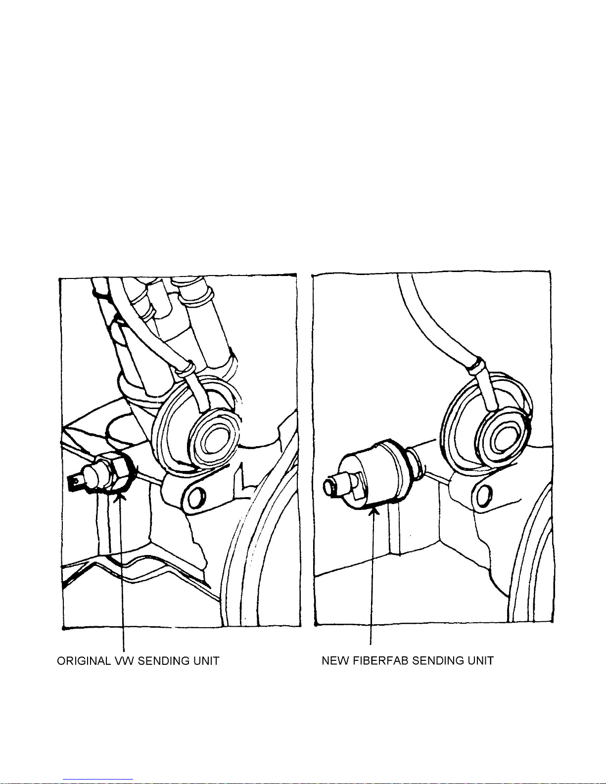
INSTALLING GAUGE SENDING UNITS
Tools Required Crescent Wrench
Parts Required Ff #X166 Temperature Sender
Ff #X169 Pressure Sender
Refer to Figures 8, 10 and 11
Remove the VW oil pressure-sending unit. This is located at the base of the distributor. Install the Fiberfab oil
pressure-sending unit in the same location. The location of the sending unit is shown in Figure 8.
Remove the oil dipstick and replace it will the oil temperature sending unit following the instructions included with
the sending unit kit. See Figure 10.
Replace the stock air cleaner with a low profile air cleaner.
Figure 8 Oil Pressure Sending Units
Page 16
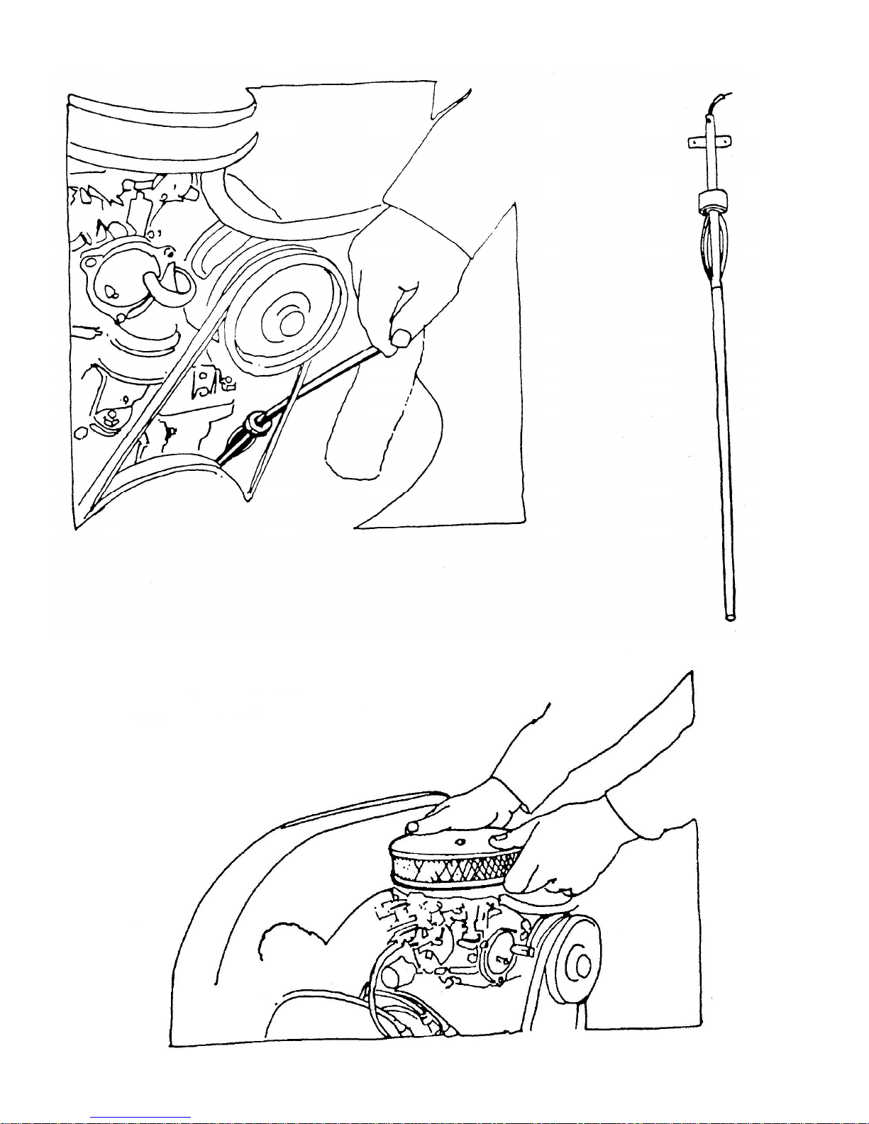
Figure 10 Oil Temperature Sending Unit
Figure 11 Air Cleaner
Page 17
INSTALLING THE CENTER CONSOLE
Tools Required Drill
3/8 inch Drill Bit
Jigsaw
3/8 inch Socket Set
Parts Required Ff #Z411 Floor Console
Ff #X120 Shifter
Refer to Figures 12, 13 and 14
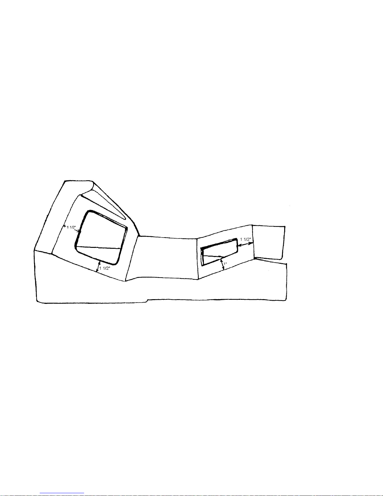
1. Cut the openings in the console for the shifter and hand brake lever. Use the plate in the shifter kit for the shifter
opening pattern. Dimensions for the hand brake are shown in Figure 12.
2. Remove the old shifter
3. Slide the center console over the hand brake lever as shown in Figure 13.
4. Install the new shifter as shown in Figure 14.
Figure 12 Lower Console
Page 18
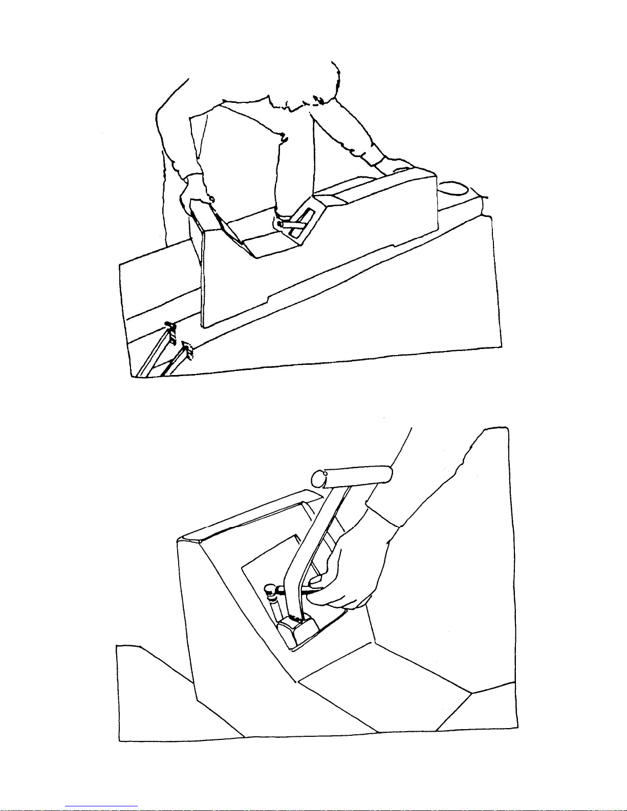
Figure 13 Installing Lower Console
Figure 14 Installing Shifter
Page 19
INSTALLING OF SPEEDOMETER CABLE
Tools Required Needle Nose Pliers
Parts Required Ff #X187 Speedometer Cable
Refer to Figure 15
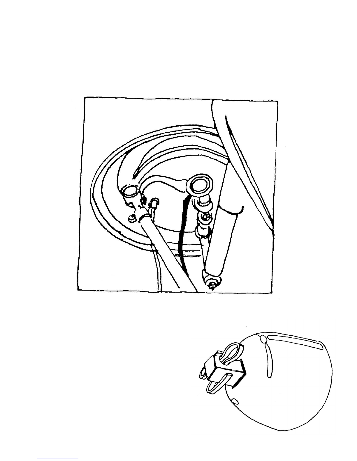
Push the speedometer cable through the left front spindle and hub dust cover. Insert cotter pin through cable end.
Figure 15A Placement of Speedometer Cable Through Wheel
Figure 15B Detail: Cable End and Cotter Pin – Outside of Wheel
Page 20
MAIN BODY PREPARATION
1. Cutting the Windshield Opening
Tools Required 40 Grit Sandpaper
Tape
Drill
3/8 inch Drill Bit
Jigsaw
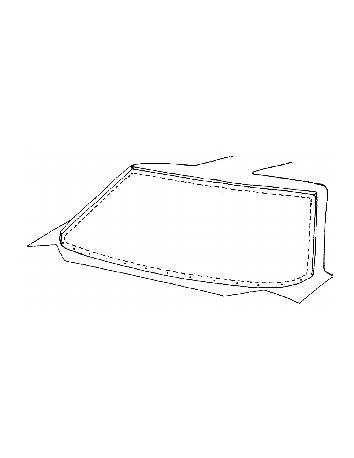
Refer to Figure 16
Cut the opening in the front of the main body for the windshield. Start the cut by drilling a 3/8-inch hole and insert
saw blade in this hole. A line is scribed ¾ inch from the lip in the body as illustrated in Figure 16. When cutting be careful
to leave the scribe mark on the finished part. Then using the 40 grit sandpaper and a sanding block, sand all the edges
smooth to the scribed mark.
Figure 16 Windshield Opening
2. Cutting the Rear Opening
Tools Required 40 Grit Sandpaper
Tape
Drill
3/8 inch Drill Bit
Jigsaw
Scribe
Refer to Figure 17
A template for the rear window opening is furnished with the assembly manual. Remove the pattern from the book
and tape it in place in the rear opening. Scribe the fiberglass around the edge of the pattern as shown in Figure 17. Cut
out along the scribed lines and sand smooth.
Page 21
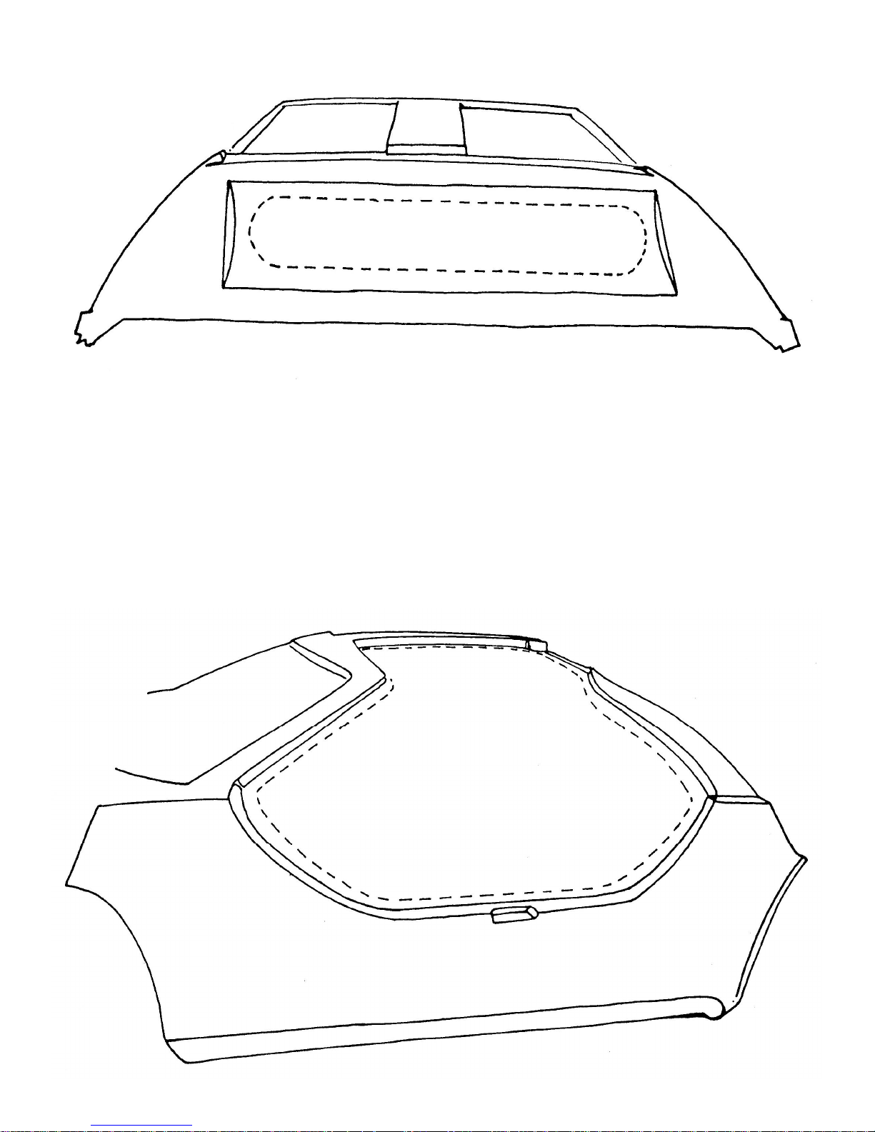
Figure 17 Rear Window Opening
3. Cutting the Door Openings
Tools Required 40 Grit Sandpaper
Tape
Drill
3/8 inch Drill Bit
Jigsaw
Refer to Figure 18.
Cut the opening on each side of the main body section. Sand to the scribed lines.
Figure 18 Door Opening
Page 22
4. Defroster Installation
Tools Required Drill
5/16 inch Drill Bit
Tape
2 – 7/8 inch wrenches or sockets
Parts Required Ff #X14111 Defroster
Bolt Kit #2
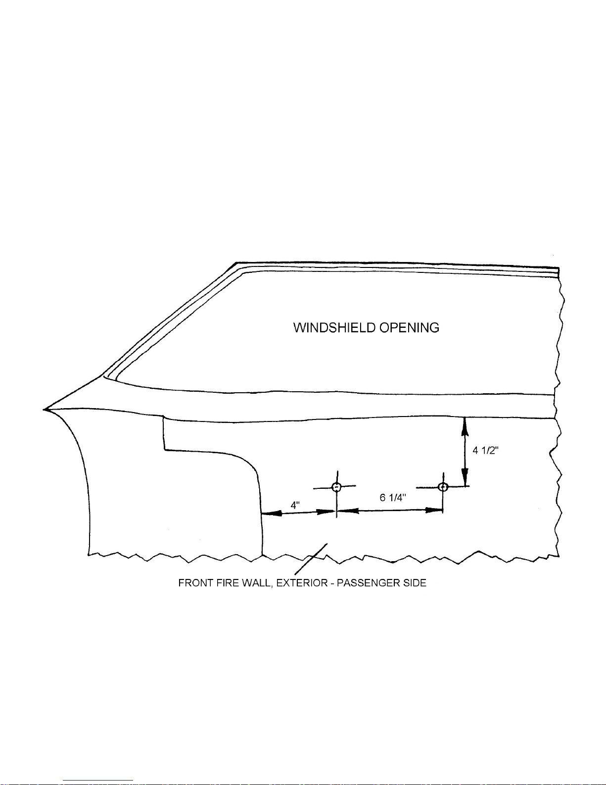
Refer to Figures 19 and 20
Measure and drill holes as shown in Figure 19 using a 5/16-inch drill bit. Install defroster motor on the inside of
the car. The air outlet ducts should face up. Bolt motor in place as illustrated in Figure 20 using the #2 Bolt Kit
Figure 19 Defroster Installation – Location of Bolt Holes
Page 23
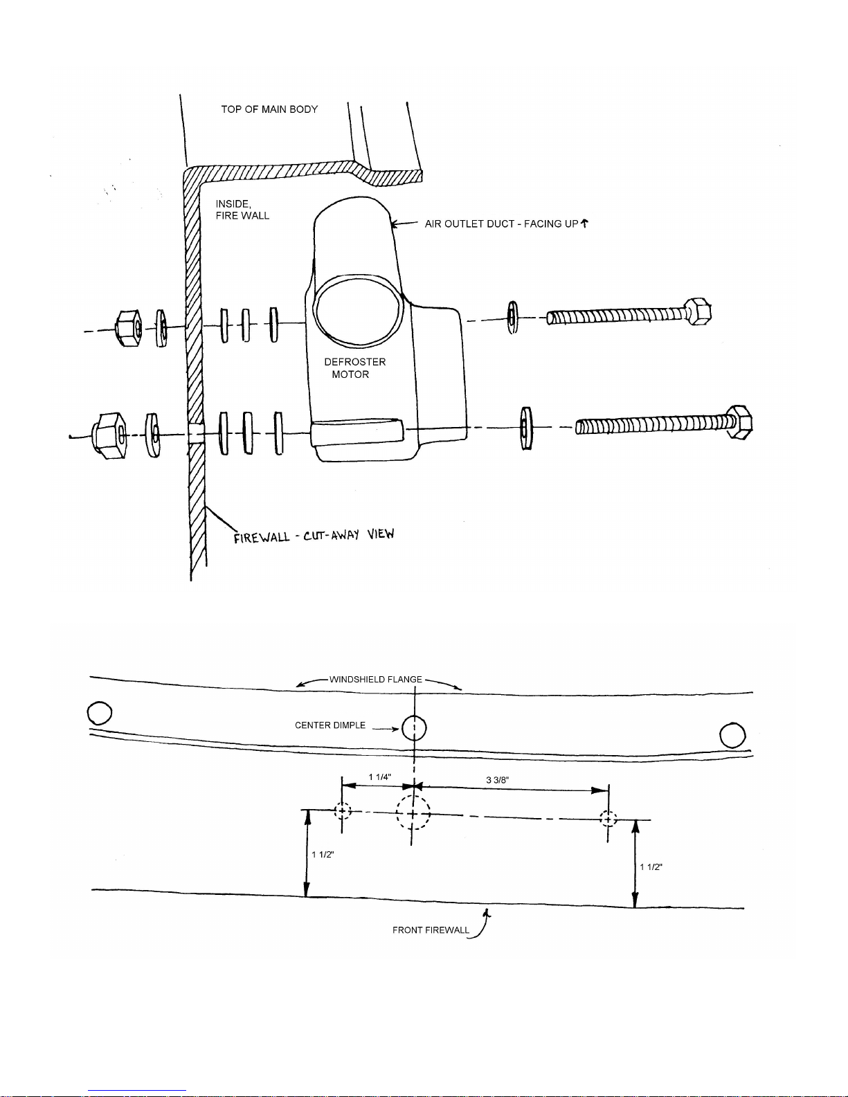
Figure 20 Detail: Defroster Installation
Figure 21 Motor Location Top View
Page 24
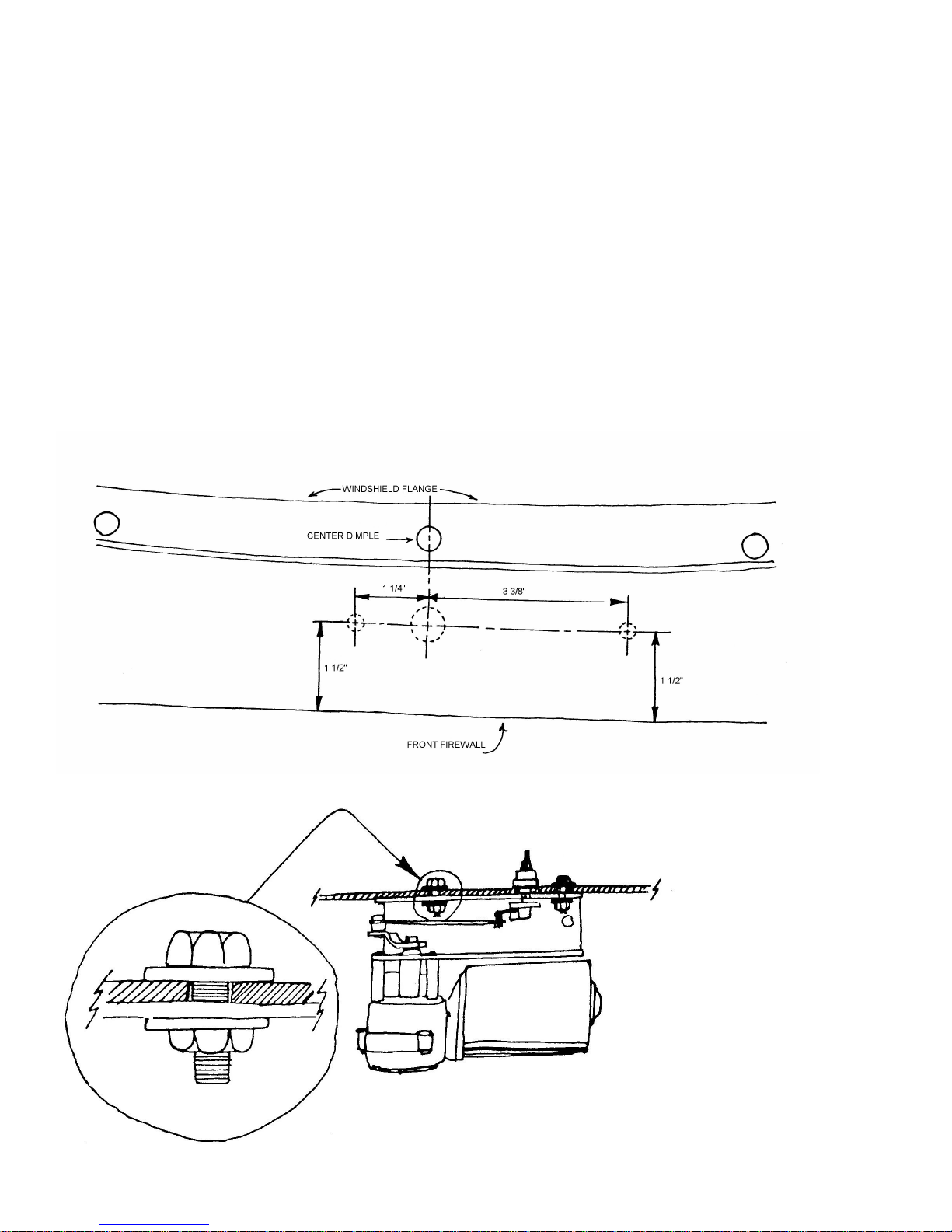
5. Windshield Wiper Motor Installation
Tools Required Drill
5/16 inch Drill Bit
5/8 inch Drill Bit
2 – 7/16 inch Wrenches
Parts Required Ff #Z767 Power Motor
Ff #Z782 Pivot Shaft
Ff #Z783 Drive Arm
Bolt Kit #3
Refer to Figures 21 and 22
Measure and mark the windshield cowl for holes to be drilled to mount the wiper motor as shown in Figure 21.
Use the dimple at the center of the windshield opening to locate the vertical line. Use a 5/8-inch drill bit to drill the center
hole for the wiper motor pivot shaft. Drill the two outer holes for the mounting bracket using a 5/16-inch drill bit. Install the
wiper motor as illustrated using bolt kit #3 as shown in Figure 22. DO NOT INSTALL wiper arm Ff #Z768 and blade Ff
#Z769 at this time.
Figure 21 Motor Location Top View
Figure 22 Wiper Motor
Page 25
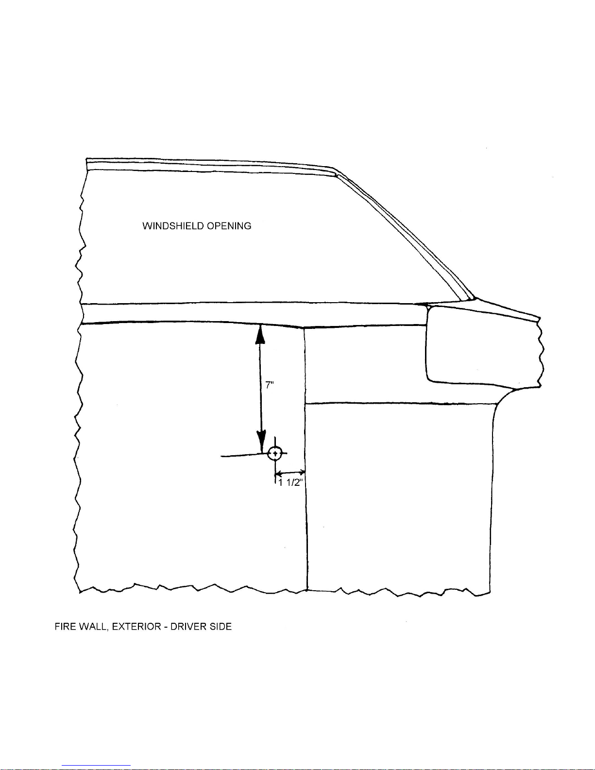
6. Drill Holes for Wiring Harness
Tools Required Drill
1-1/2 inch hole saw
Refer to Figures 23 and 24
Use a 1-1/2 inch holes saw to drill holes in the firewall and inner liner as shown in Figures 23 and 24.
Figure 23 Wiring Harness – Drill Hole Location
Page 26
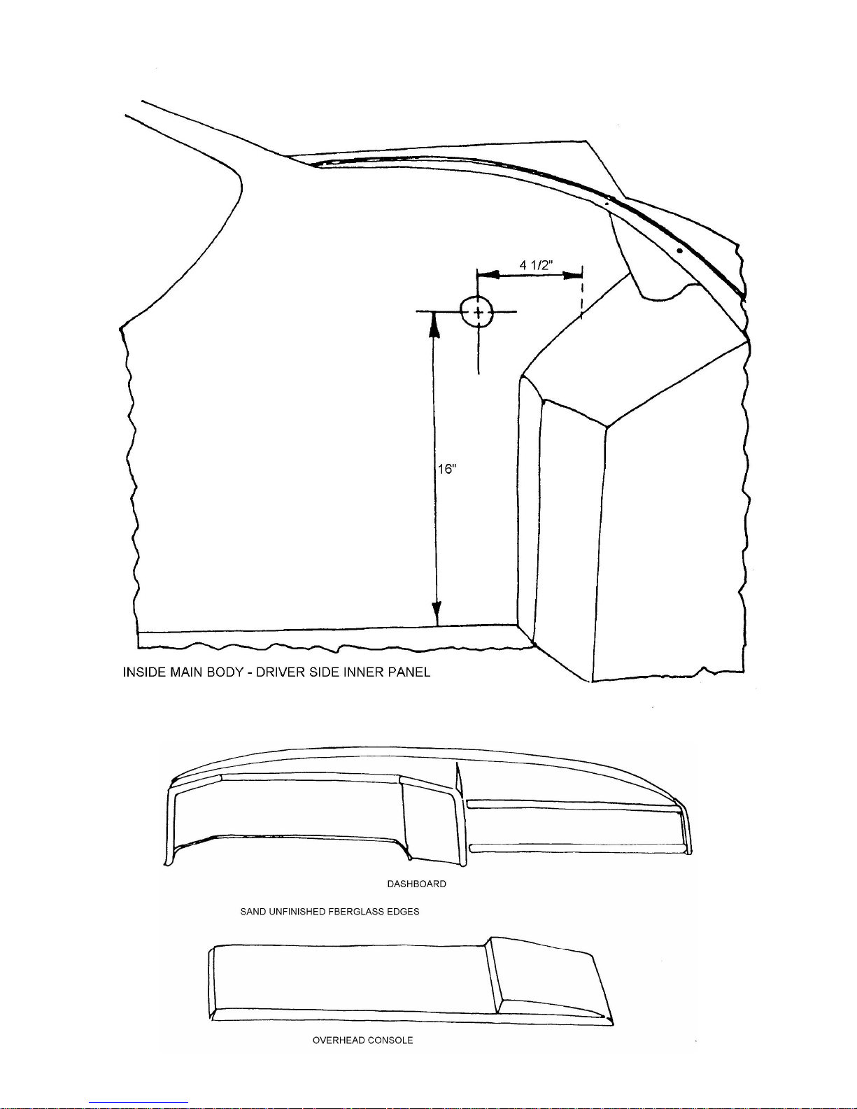
Figure 24 Wiring Harness – Drill Hole Location
Figure 25 Dashboard and Overhead Console
Page 27
7. Preparation of Dash and Overhead Console
Tools Required 40 and 120 Grit Sandpaper
Jigsaw
Flat Black Paint
Medium Steel Wool
Scissors
1-1/2 inch brush
Drill
¼ inch Drill Bit
3 inch Hole Saw
2-1/6 inch Hole Saw
1-1/2 inch Hole Saw
¾ inch Hole Saw
½ inch Hole Saw
Rattail File
Parts Required Ff #Z410 Overhead Console
Ff #MX194 Contact Cement
Ff #Z409 Dash
Ff #Z788 Veneer
Ff #X141H Defroster Kit
Ff #Z759J Dash Pad
Refer to Figure 25 Through 30
Trim all flanges using 40 grit sandpaper. Then sand smooth using 120 grit sandpaper. Using medium steel wool,
rub the entire dash and console until the glass is removed. Then spray with flat black paint supplied with the kit.
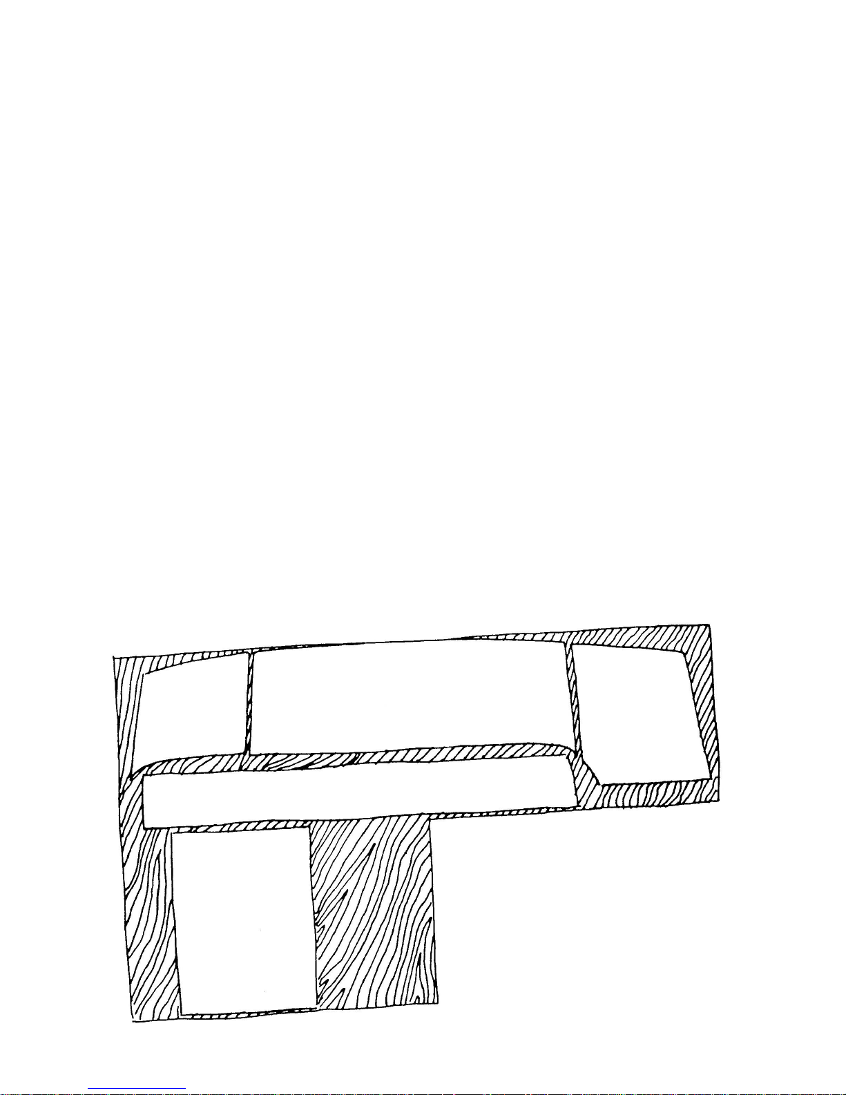
Remove the template from the assembly manual and lay them out on the veneer as shown in Figure 26. Trace
the edges of the templates on the veneer and cut the veneer as just marked using scissors. Check to see that veneer fits
the dash and overhead console.
Figure 26 Layout of Templates on Veneer
Page 28

Use a brush to apply contact cement to the back of the veneer and faces of the cash and console. Follow
instructions on the can of cement and apply the veneer to the cash and console.
Mark the veneer for holes to be drilled for gauges and switches mounted in the dash and console using the
templates. Now drill all the holes using the proper size drill bits and hole saws as indicated on the templates.
Drill holes in top of the dash for defroster outlets at location shown in Figure 28. Slide the dash pad over the
dashboard. Push the pad back as tightly as possible and mark the location of the defroster outlets from under the dash.
Remove the dash pad and cut the holes for the outlets where marked. Replace the pad on the dash and instill defroster
outlets as shown in Figure 30.
Figure 27 Drill Through Dashboard and Veneer Per Templates
Figure 28 Location of Defroster Vents
Figure 29 Padded Dash Over Dashboard
Figure 30 Defroster Vent Installed In Dashboard
8. Installation of Gauges and Switches
Tools Required Needle Nose Pliers
Pliers
Screwdriver
Socket Set – ¼ inch
Parts Required Ff #Z409 Dashboard
Ff #Z410 Overhead Console
Ff #X161 Speedometer
Ff #X162 Tachometer
Ff #X165 Oil Temperature Gauge
Ff #X164 Fuel Gauge
Ff #X163 Ammeter
Ff #X135 Turn Signal Indicator Lights
Ff #X135 High Beam Indicator Light
Ff #X132 Ignition Switch
Ff #X142 9 Switches
Ff #Z784 Wiring Harness
Refer to Figure 31
Install all gauges and switches in dash and overhead console as shown in Figure 31. Wire dashboard according
to instructions included with the wiring harness. Do not wire the overhead console.
Page 29

Figure 31A Dashboard Layout for Gauges
Figure 31B Overhead Console Layout
Page 30
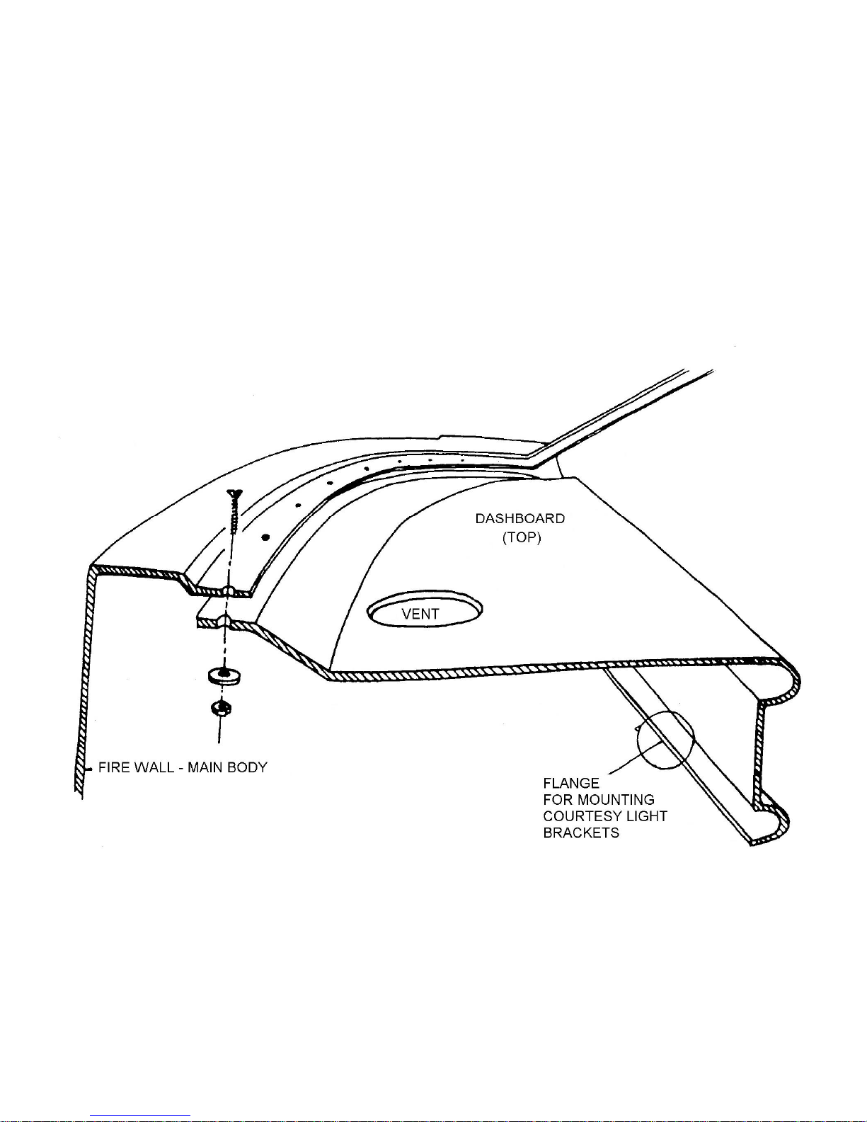
9. Installation of Dashboard
Tools Required Drill
3/16 inch Drill Bit
Philips Screwdriver
3/8 inch Wrench
Pop River Gun
Parts Required Bolt Kit #4
Ff #M5604B Wiring Harness Clamp
Refer to Figure 32
Place dash under the windshield opening and drill through the body and dash at the dimples using a 3/16-inch
drill bit as shown in Figure 32. You will heed a helper to hold the dash in place while drilling. Bolt dash to body using bolt
kit #4.
Figure 32A Installing Dashboard
Page 31
Courtesy Lights
Tools Required Electric Drill
4 inch Drill Bit
Tape Measure
2 – 7/16 inch Wrenches
Parts Required Ff #Z777 Courtesy Light Plates
Ff #Z758 Courtesy Lights
Bolt Kit #4
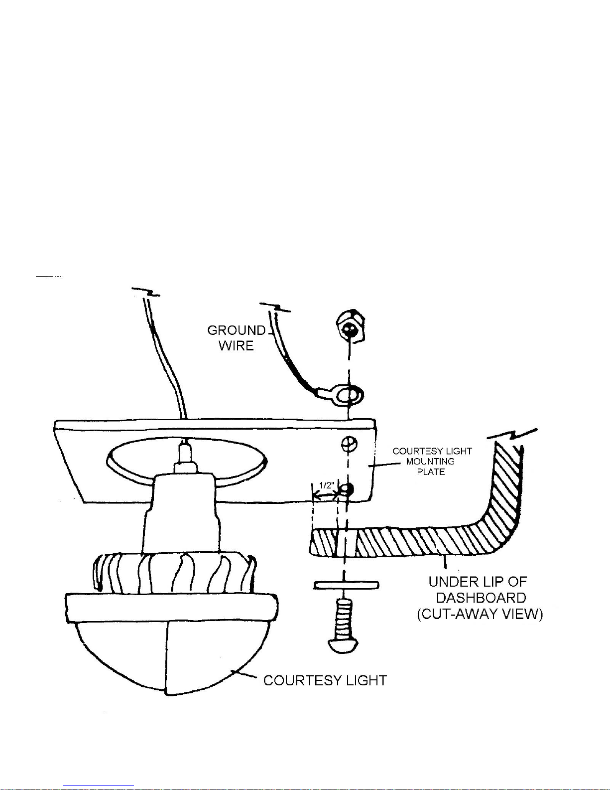
To install courtesy lights, position mounting plate 4 inches in from each end of the underside of the dash flange,
with the hole for the light towards the firewall at the front of the main body. Allow ½ inch of fiberglass from the edge of the
flange to the edge of the bolt holes as shown in Figure 32B. Use the plate as a template to scribe mounting holes on the
underside of the dash flange and drill using a ¼ inch drill bit. Bolt the plate to the dash flange attaching the ground wire
from the light to one of the bolts according to the wiring diagram.
Insure the courtesy light is put into the bracket with the bulb facing downwards. Connect the wiring according to
the wiring diagram.
Figure 32B Installing Courtesy Light
Page 32
10. Routing the Main Body Wiring
Tools Required Drill
3/16 drill bit
Pop rivet gun
Parts Requires Ff #M560E Fuse Block
Ff Bolt Kit #5, #6
Refer to figure 33, 34 and 35
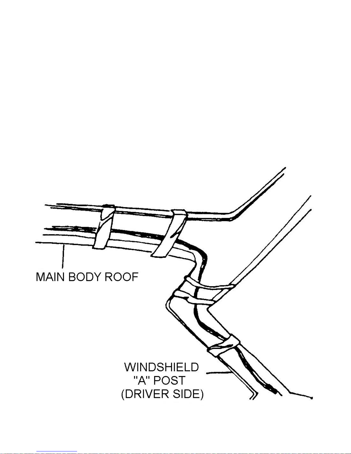
Run the wiring for the overhead console in the windshield ‘A’ pillar and tape the harness in place as shown in
Figure 33. Drill six evenly spaced holes in the reinforcing pipe with a 3/16 drill bit. Using the pop rivets in bolt kit #5, pop
rivet six wire harness clamps around the wire bundle to the reinforcing pipe as shown.
Run the wire bundles through the holds drilled earlier in the firewall and inner panel as shown in Figure 34.
Locate the fuse block inside the car as shown in Figure 35. Drill two 3/16 holes to mount the fuse box and fasten
the unit in place using the pop rivets in bolt kit #6.
Figure 33A. Wiring Harness Route
Page 33
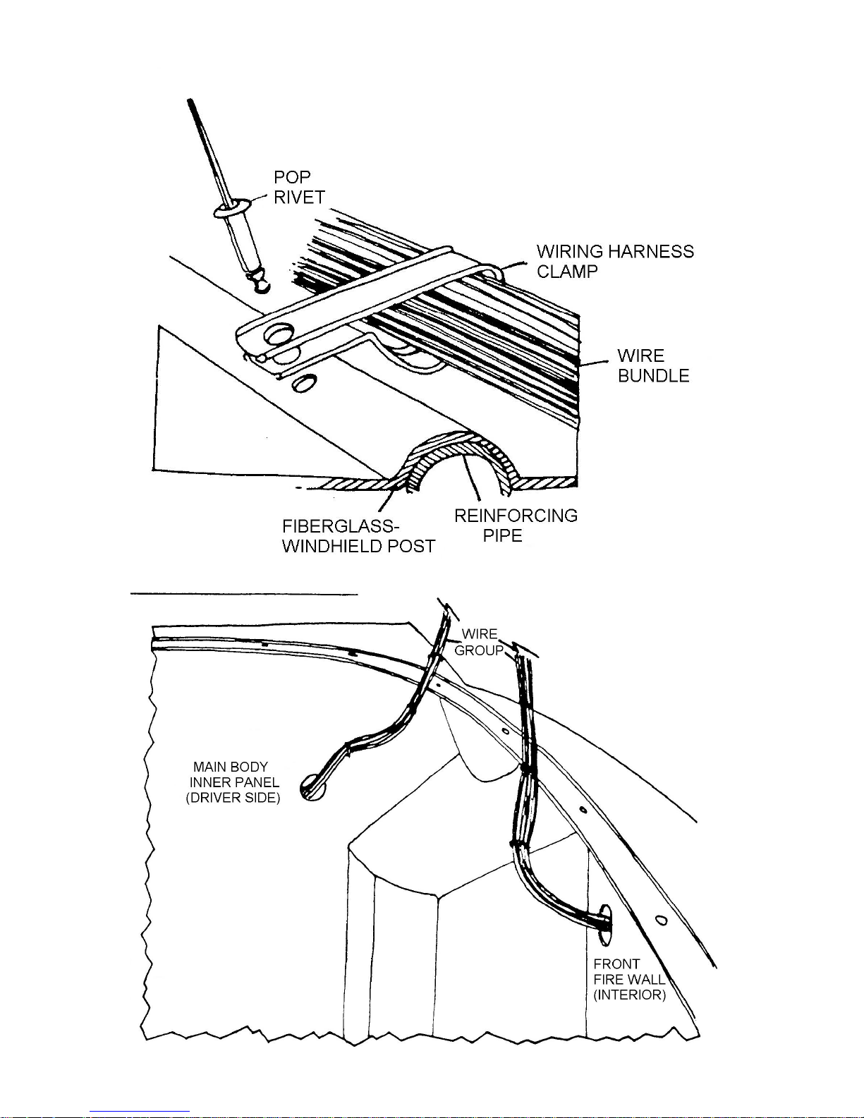
Figure 33B. Detail Wiring Harness Clamps to Reinforcing Pipe
Figure 34 Wiring Harness Routing
Page 34
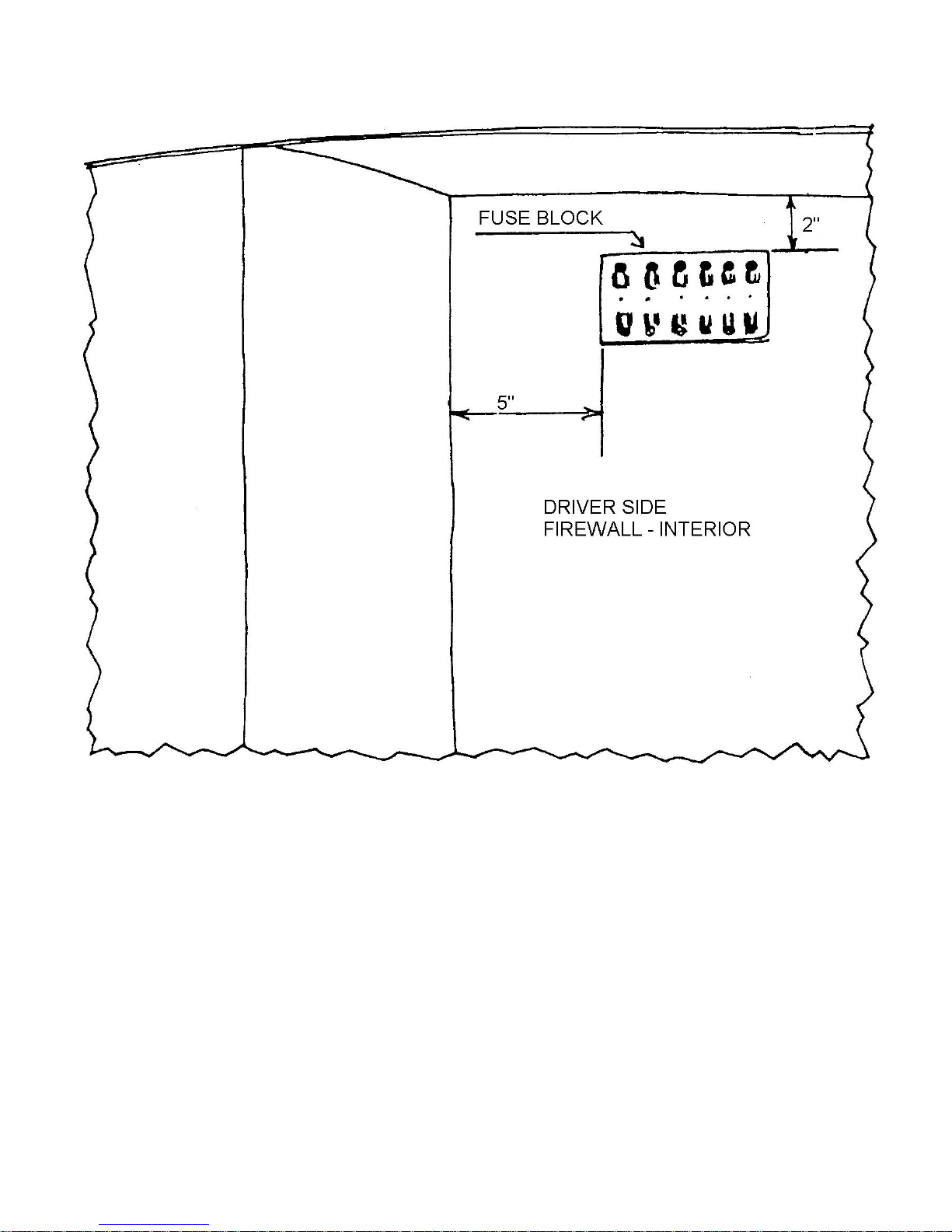
Figure 35 Fuse Box Installation
Page 35
INSTALLING THE MAIN BODY ON THE FLOOR PAN
Tools Required Caulking gun
Drill
3/8 drill bit
¼ drill bit
1/8 drill bit
3/16 drill bit
Socket Set
9/16 wrench
7/16 wrench
Phillips Screwdriver
Pop Rivet Gun
Jigsaw
40 grit Sandpaper
1-1/2 paintbrush
5/16 drill bit
Screwdriver
Parts Required Ff #X130 pan gasket
Ff #MX193 Silicone
Body Washers saved from VW
Bolt Kit #7, #8, #9, #10 and #11
Ff #MX194 Contact Cement
Ff #M554 Piano Hinge
Ff #2759K hinge gasket
Refer to figures 36 through 44
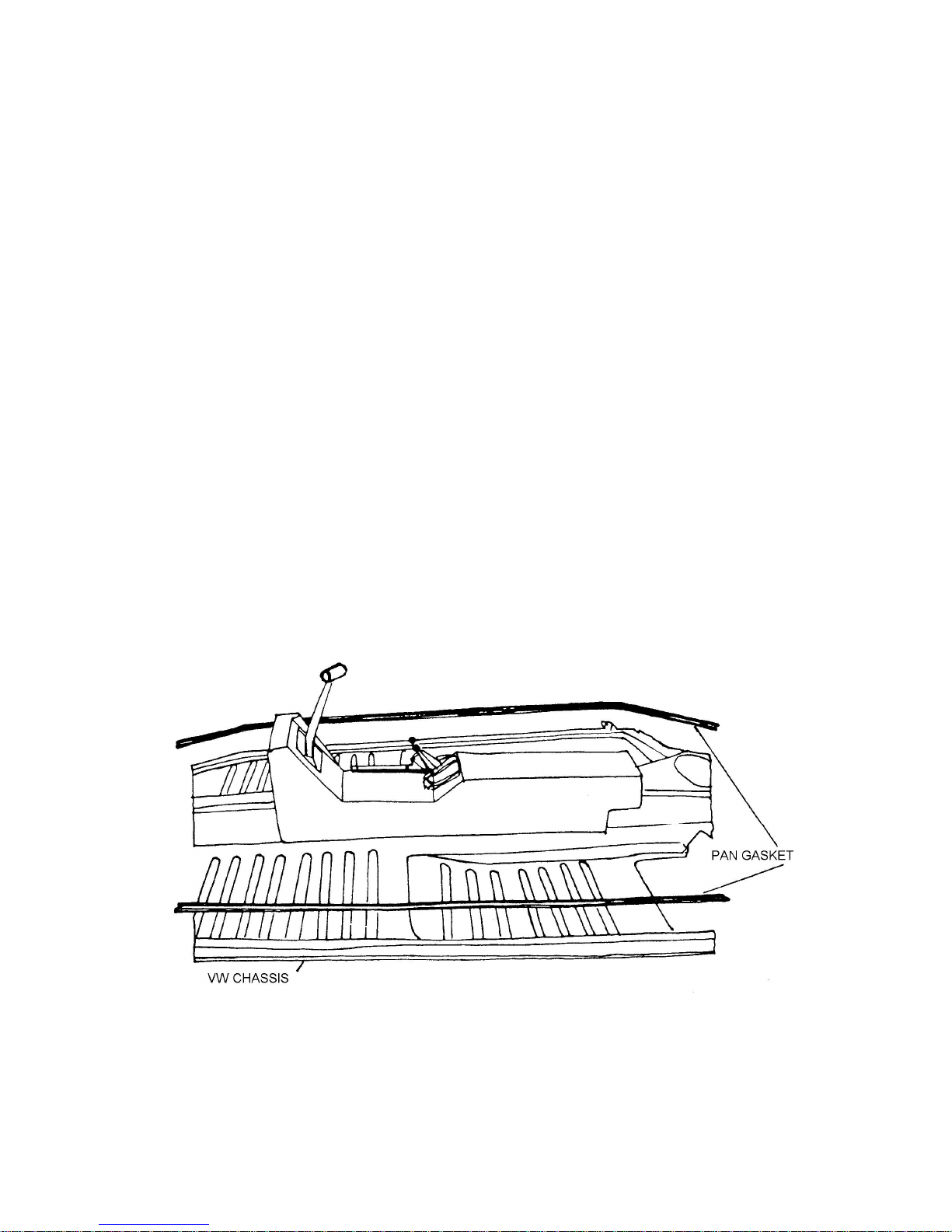
Align pan gasket over the edge of the floor pan as shown in Figure 36. Attach the gasket to the pan by placing a
dab of silicone about the size of a penny every two feet or so. Press the gasket down before the silicone sets.
Figure 36 Floor Pan Gasket to Chassis
Place the man body section on the pan and move rearward as far as the rear body flange will allow. Make certain
the side flanges fir over the ridge in the pan as shown in figure 37.
Once the body is in position, drill up through the pan gasket and body flanges with a 3/8 drill bit, using the existing
holes in the pan as a guide as shown in Figure 38. Using the ‘U’ shaped body washers saved from the original VW and
bolt kit #7, fasten the body to the pan. Use a fender washer between the bolt head and the fiberglass and the ‘U’ shaped
washer between the pan and the securing nut. Place the front and rear center console rugs under the console as
illustrated in Figure 39.
Page 36
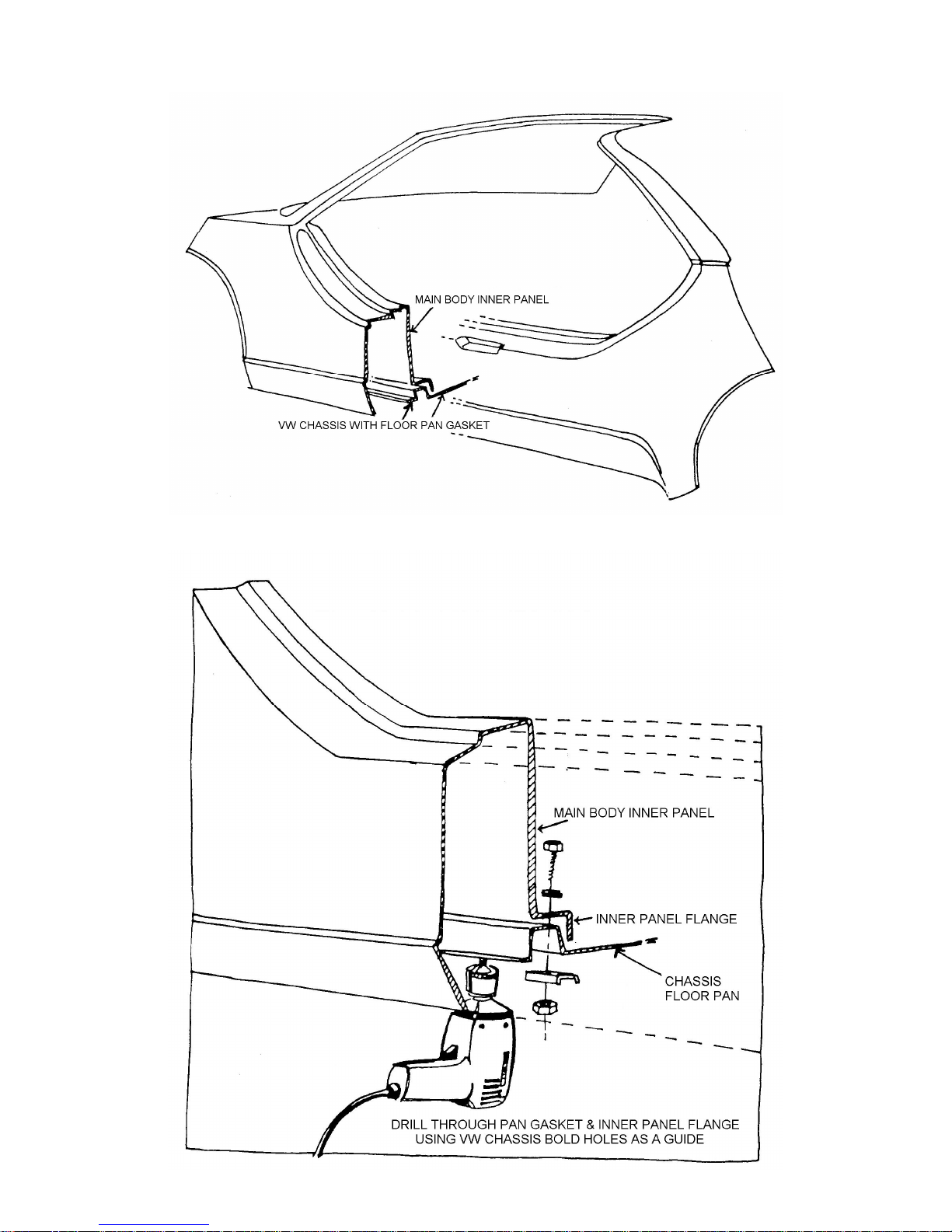
Figure 37 Mounting Main Body to Chassis.
Figure 38 Detail: Main Body to Chassis
Page 37
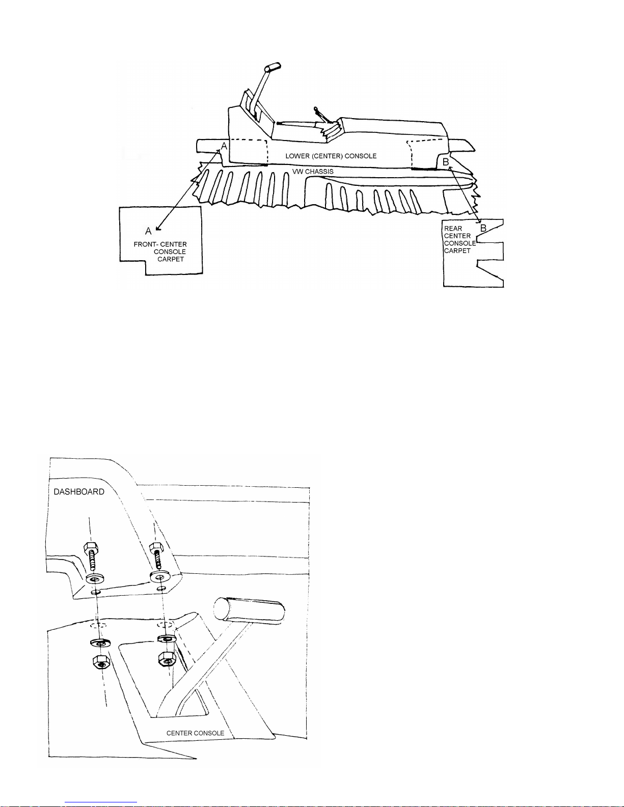
Figure 39 Carpeting Beneath Lower Console.
Bolt the center console to the dash as shown in Figure 40. Mark the console as shown in Figure 41. Drill through
the console and chassis tunnel with a 1/8-drill bit. Fasten the console to the tunnel using bolt kit #9 in the holes drilled.
Cut the flanges on the battery box and luggage compartment as shown in Figure 42 and sand the edges smooth.
Hold the box in place as illustrated and drill through the box and rear of the main body section using a 3/16 drill bit.
Remove the box and run a bead of silicone along the flanges. Pop rivet the box in place using bolt kit #10.
To install the top of the battery box/luggage compartment, first cement the gasket cover to the piano hinge with
contact cement. Place the hinge on the cover, align the center of the hinge with the edges of the compartment cover and
drill the holes in the hinge through the cover with a 3/16 drill bit. Remove the hinge and run a bead of silicone on the hinge
as shown in Figure 43. Using bolt kit #11 pop river the hinge to the cover as in Figure 43.
Figure 40 Bolting Dash to Center Console.
Page 38
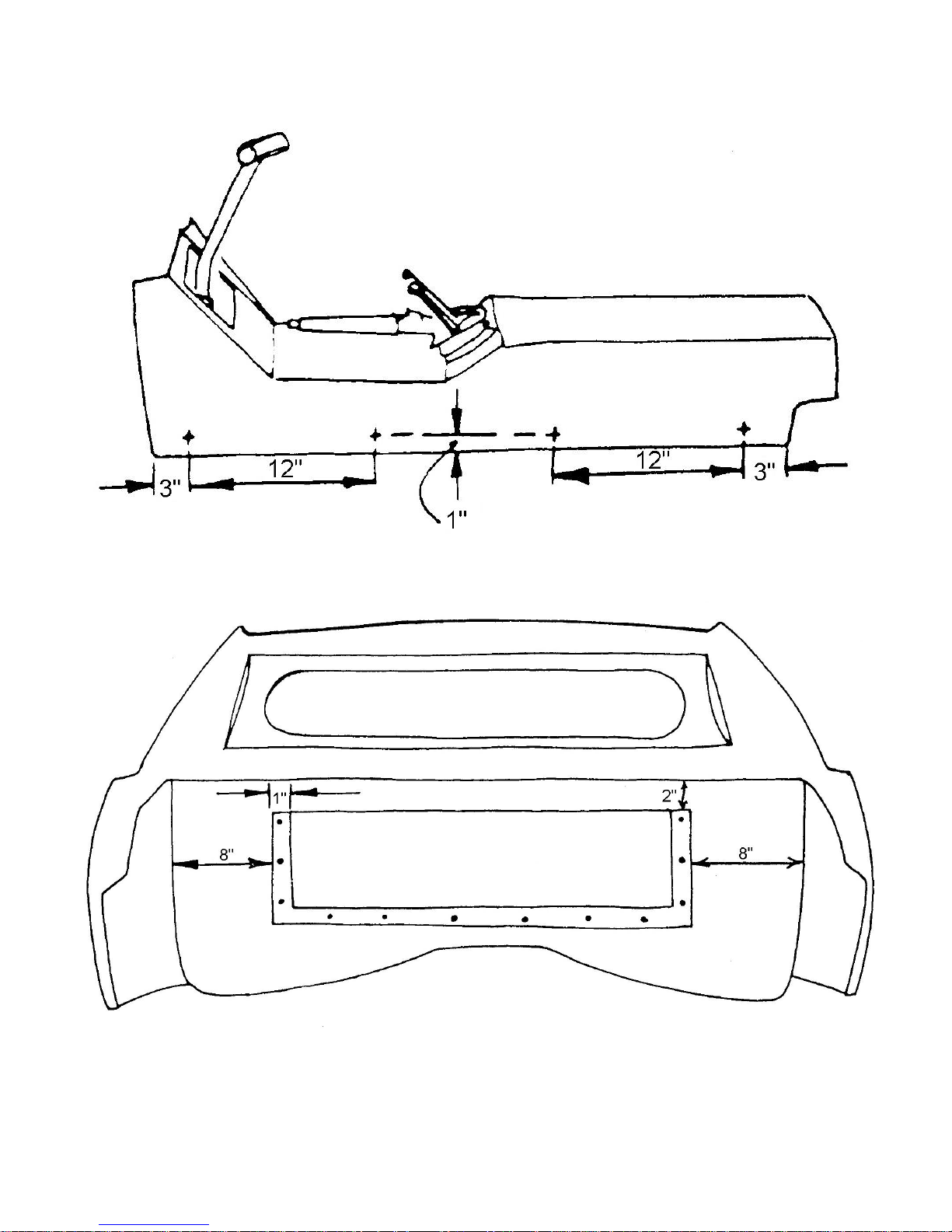
Figure 41 Center Console to VW Floor Pan Location of Bolt Holes
Figure 42 Position Luggage Box on Main Body
Page 39
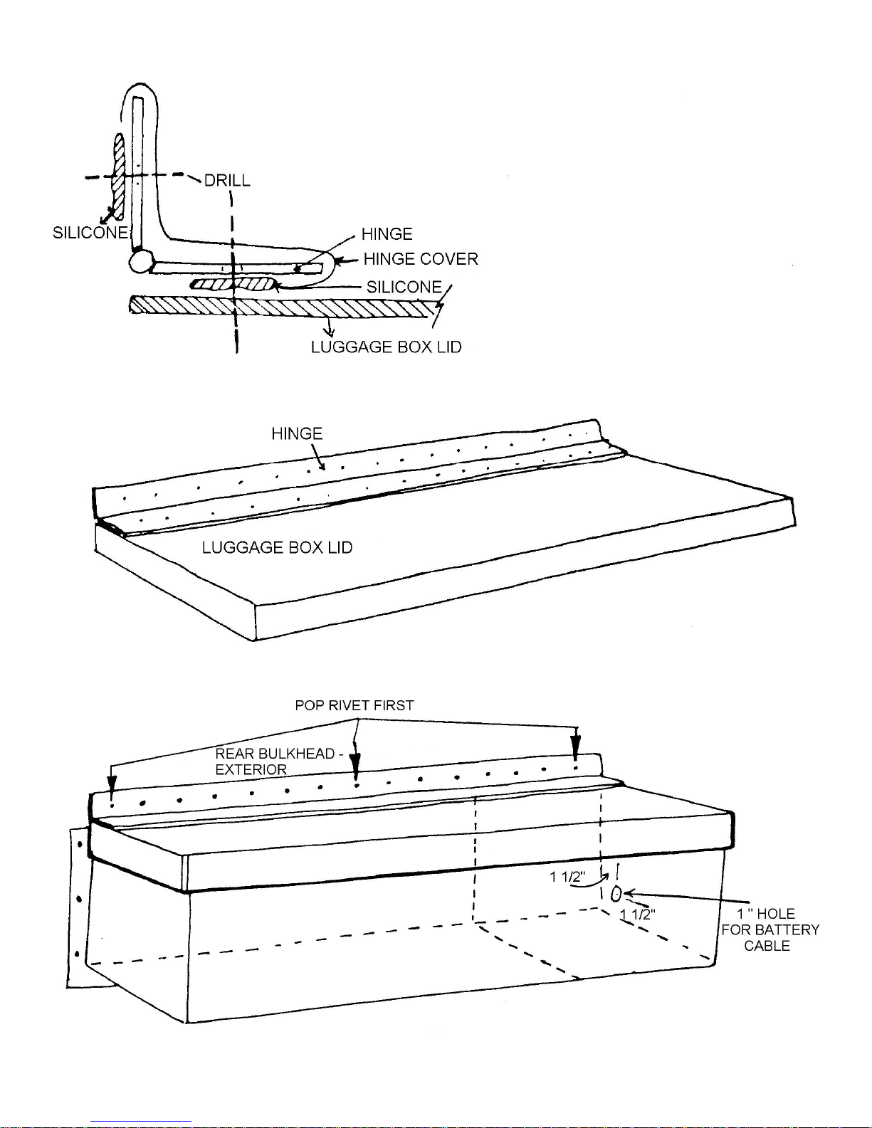
Figure 43 Luggage Box Lid and Hinge Attachment
Figure 44 Mounting Lid to Main Body
Page 40
THE GULL WING DOORS
1. Preparing the Gull-Wing Doors.
Tools Required Assorted files
40, 80 and 120 grit sandpaper
Putty Knife
Parts Required Body Filler
Refer to Figure 45
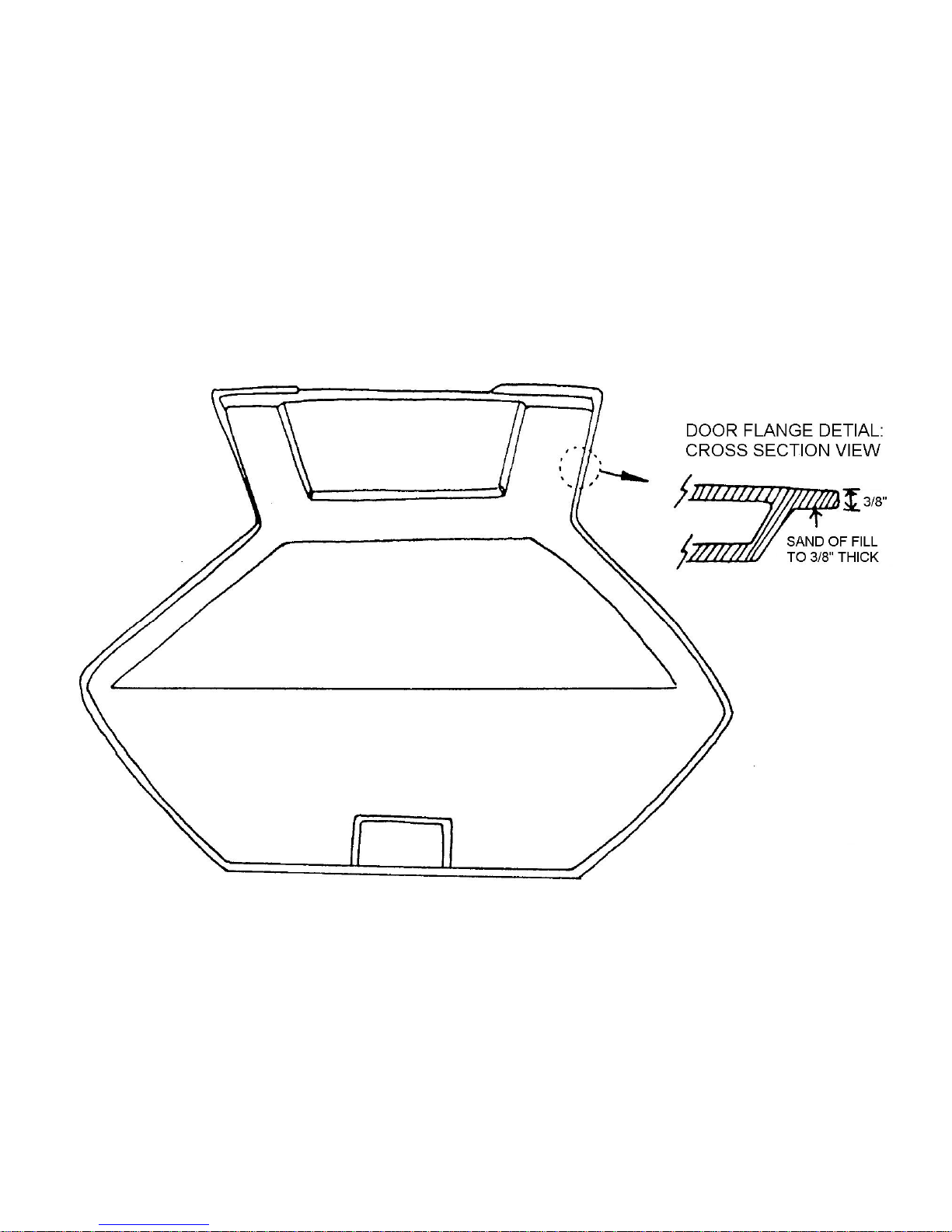
File and sand the inside of the door edges to about 3/8 thick as shown in figure 45. Fill low spots with body filler if
necessary.
Figure 45A. Door Flange Preparation
Page 41
2. Cutting the Side Window Openings
Tools Required Drill
3/8 drill bit
Jigsaw
Tape
40 and 80 grit sandpaper
Refer to Figure 45
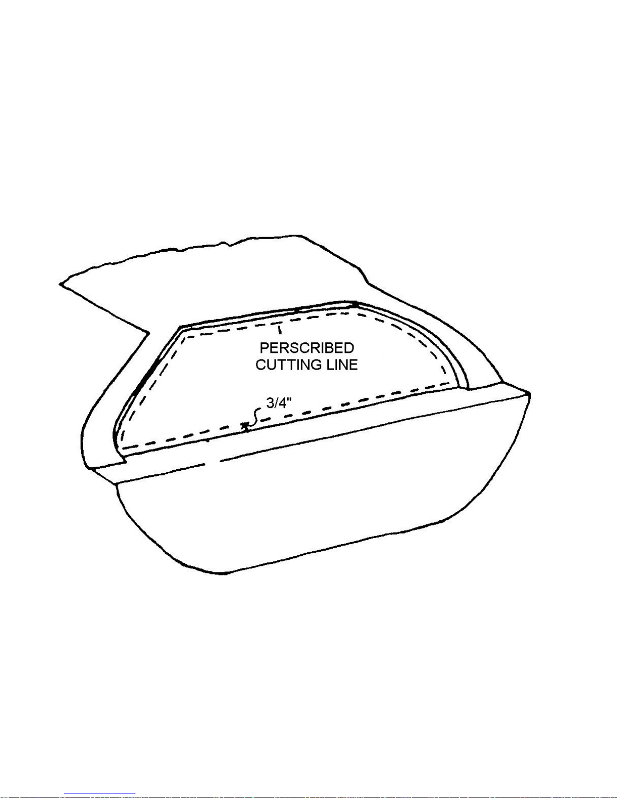
Drill a 3/8 hole in the area where the side glass will be installed. Use the hole for starting the cut with the jigsaw.
Cut the opening out and sand to the scribe line as shown. This will leave a ¾ flange for the glass to seal against as shown
in Figure 45.
Figure 45B Cutting Side Window Opening
Page 42
3. Preparing the Door for Latches
Tools Required Drill
6 Inch Hole saw or Jigsaw
Tape
¼ Drill bit
Rattail file
Scissors
Medium Steal Wool
Parts Required Ff #Z731 Door Latch Plate
Ff #Z787 and #Z725 Door Lock Kit
Ff #X137 Flat Black Paint
Refer to Figures 46 through 49
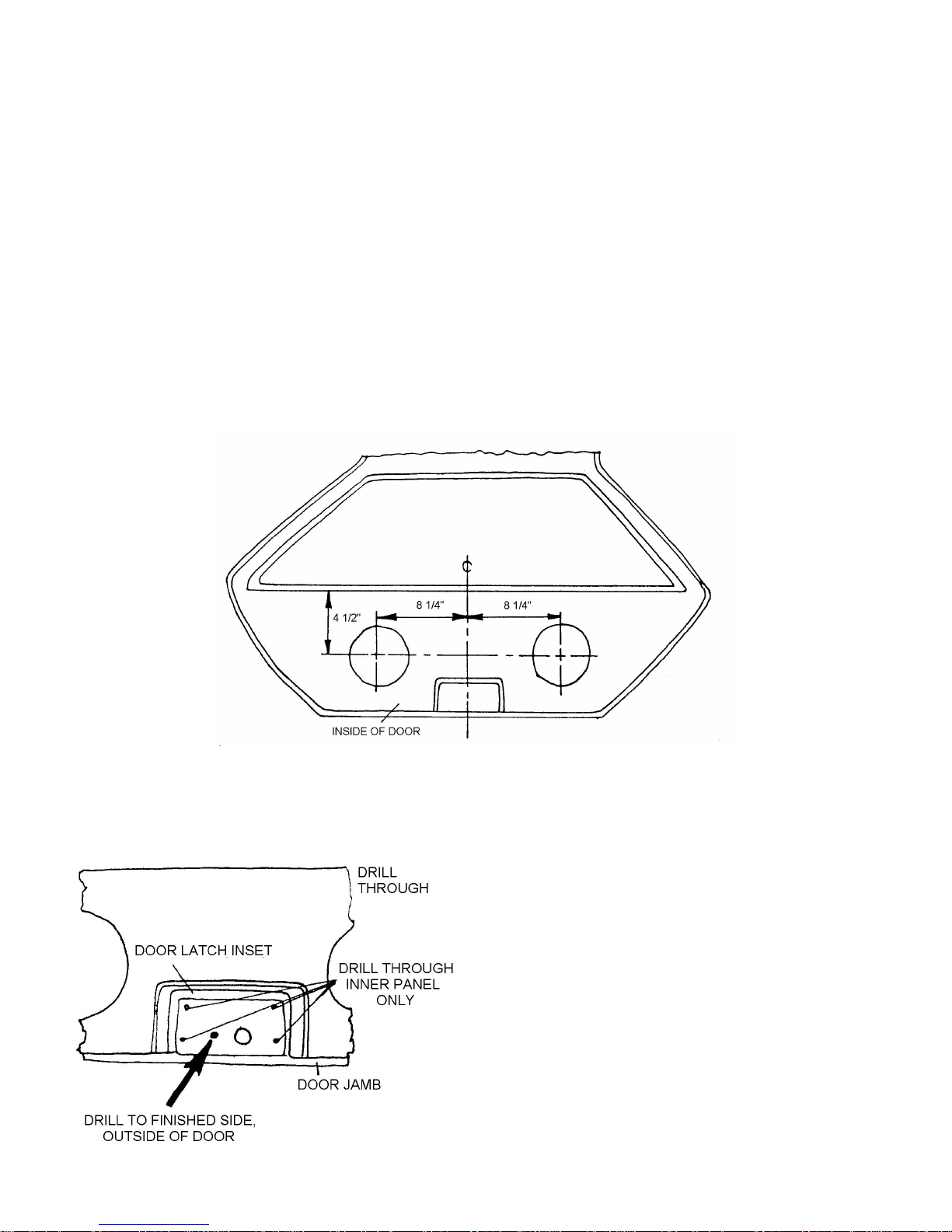
On the inside of the door measure 8-1/4 left and right of the center of the door latch indent and 4-1/2 down from
the top of the door flange. Mark the intersection of the measurement and cut 6 inch holes at these points as show in
Figure 46.
Figure 46 Access Holes for Installing Door Latch.
In the kit are two steel plates for the door latches. Position the plate in the latch inset making certain the plate is
resting on the bottom of the door jamb as shown in Figure 47. Drill five ¼ holes as shown. The hole indicated by the arrow
should go completely though the outer door skin.
Figure 47 Latch Plate Mounting Holes
Page 43
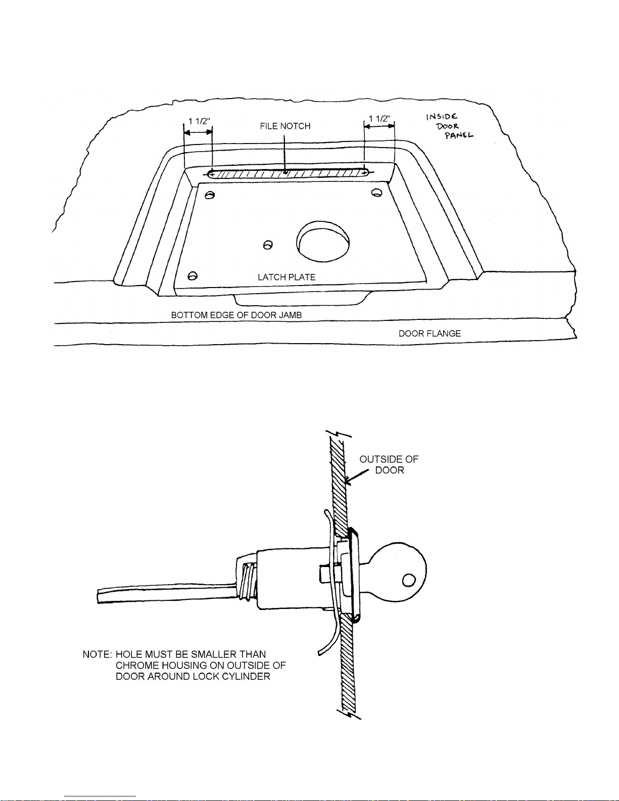
On the door latch inset, measure 1-1/2 inches from each corner and drill two 5/16 inch holes. Use a rattail file to
open a notch between the holes as shown in Figure 48A.
Figure 48A Notching Door Latch Inset
The ¼ inch hole drilled though the outside door skin earlier is for the door lock cylinder. A pattern of the lock
cylinder should be made and traced around the ¼ inch hole. The hole should then be opened up with a rattail file to match
the tracing. Install the lock cylinder in the door as shown in Figure 48B
Figure 48B Door Lock Cylinder
Page 44
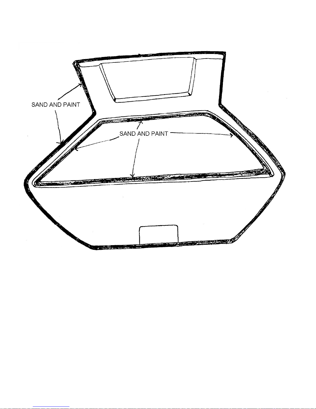
Use medium steel wool to sand the door flange and window opening. Paint these areas with the flat black paint as
shown in Figure 49.
Figure 49A Preparing Door and Window Flanges
Page 45
4. Locating the Door Hinges
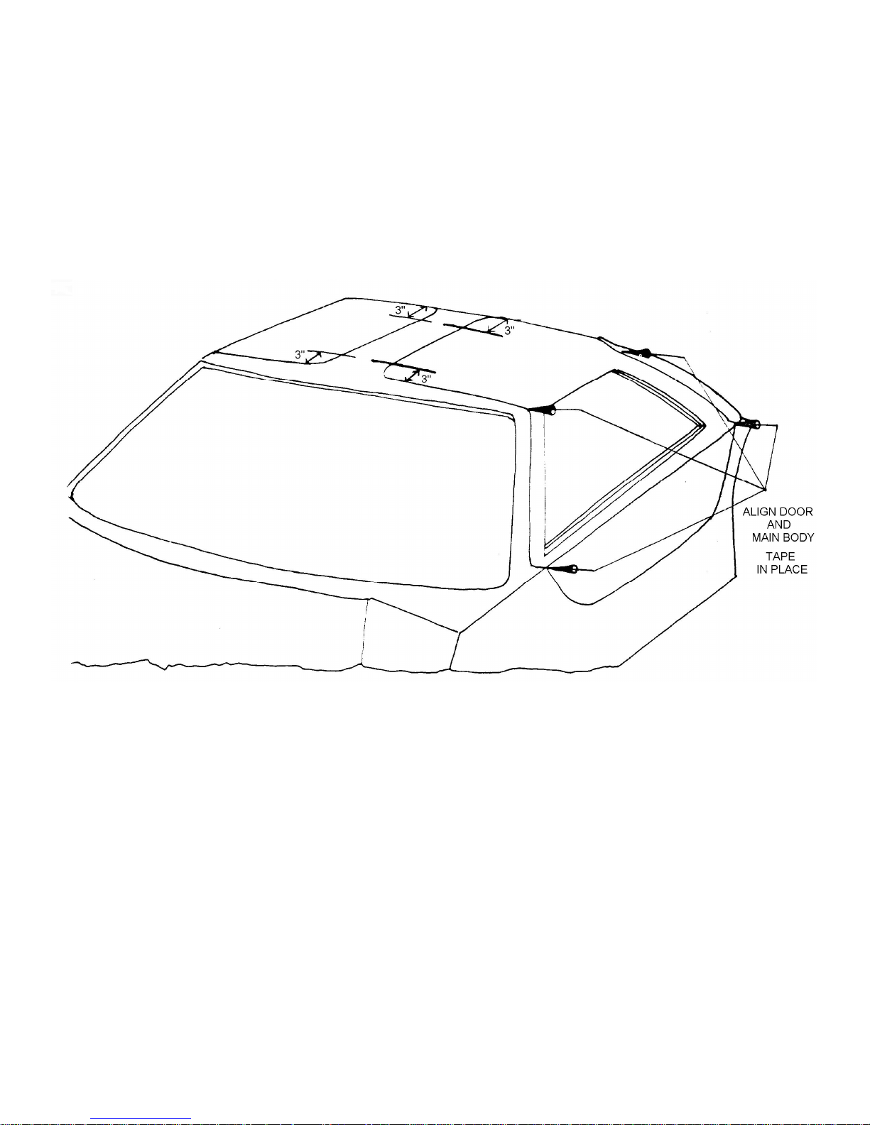
Tools Required 1-1/2 Masking Tape
Refer to Figure 49B
Place the door in the main body door opening and align the top of the door with the roof of the main body and the
lower edges of the door with the body. When you are satisfied with the door alignment, tape the door in place.
Measure 3 inches from each outer edge of the door roof and continue the line onto the main body roof as shown
in Figure 49B
Figure 49B Location of Door Hinges
Page 46
5. Mounting the Door Hinges
Tools Required Drill
3/16 inch Drill Bit
Tape
Philips Screwdriver
3/8 inch Wrench
40 and 80 grit Sandpaper
Parts Required Ff #M553 Hinges
Bolt Kit #12
Refer to Figures 50A, 50B and 51
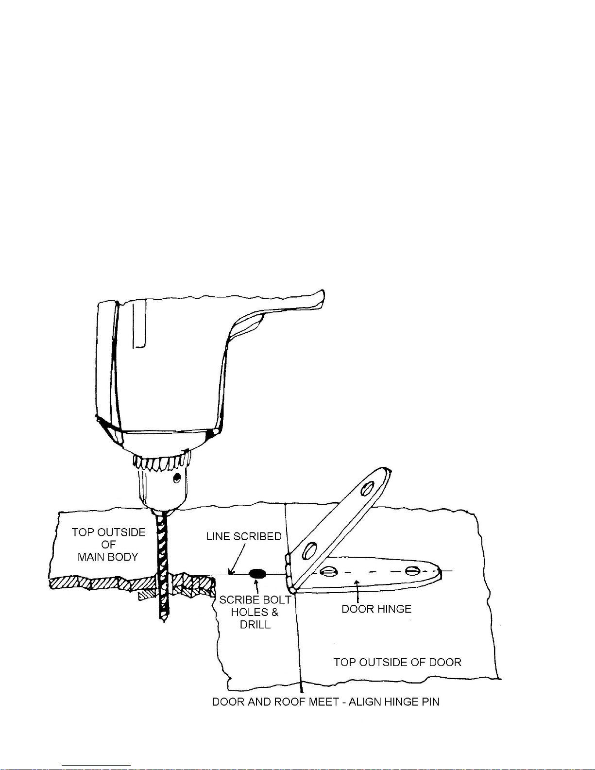
Position the holes in the door hinge over the lines drawn on the roof and the door top. Center the hinge pins over
the space between the door top and the main body roof. Mark the door top and main body roof through the holes in the
hinges. Mark all four hinge holes and remove the hinges
Drill a 3/16-inch hole at all sixteen marks. Drill completely through the fiberglass and the inset metal plate in the
roof to the inside of the cockpit area on both the doors and the main body roof as shown in Figure 50A.
Figure 50A Locating Door Hinge Mounting Holes
Page 47
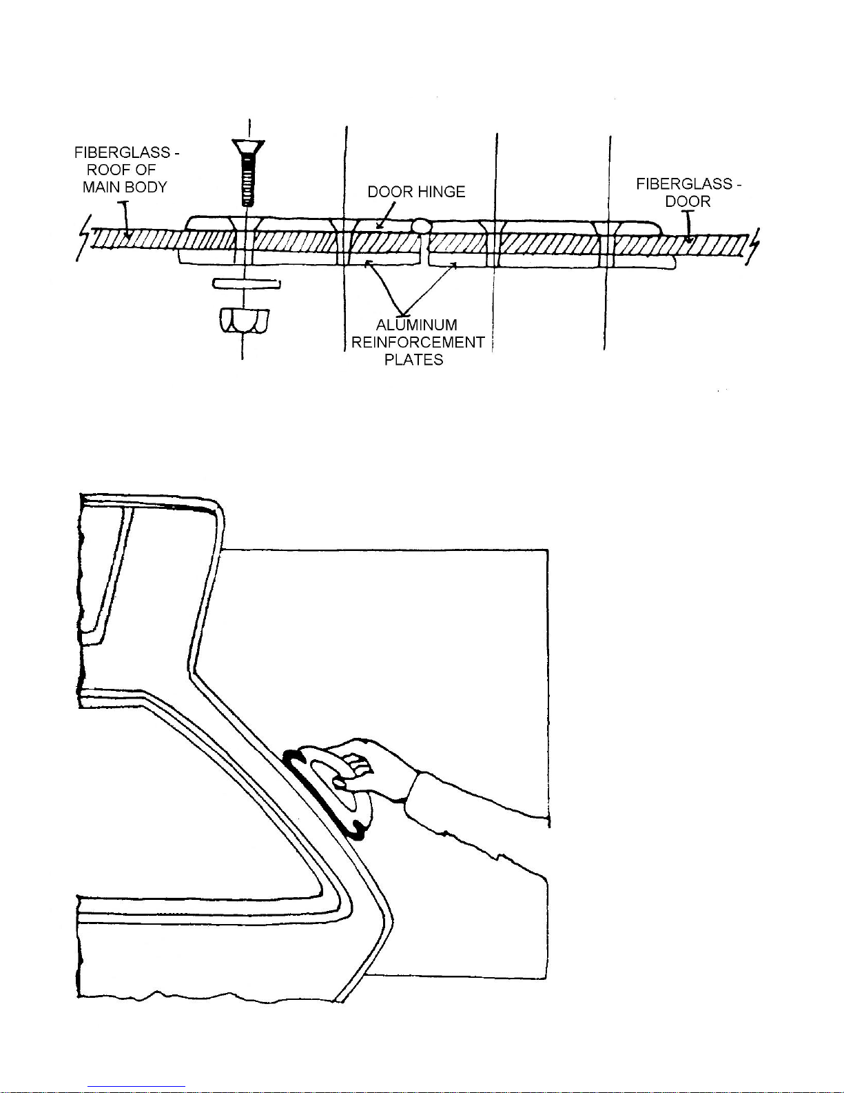
Bolt the doors to the main body through the hinges with bolts and huts in bolt kit #12 as in Figure 50B.
Figure 50B Mounting Door Hinges
Open and close the doors to be certain they operate freely. It may be necessary to sand the outer door flange as
shown in Figure 51.
Figure 51 Sand Door to Fit Opening.
Page 48
6. Installing the Door Assist Cylinders
Tools Required Drill
3/16 inch drill bit
Philips Screwdriver
3/8 inch wrench
1-1/2 inch masking tape
¼ inch X 20 Tap and Handle
Parts Required Ff #Z772 Cylinder Brackets (4)
Ff #Z729 Assist Cylinder Ball Stud (8)
Ff #Z727 Door Assist Cylinders (4)
Ff #Z728 Assist Cylinder Safety Clip
Bolt Kits #13 and #14
Refer to Figures 52A, B, C, 53A through E
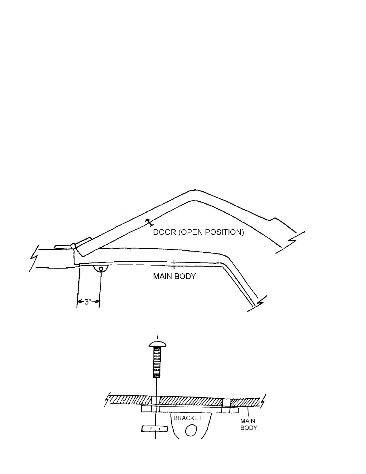
Open the door and locate the assist cylinder bracket on the main body door flange by measuring 3 inches from
the edge of the main body door opening. Using the holes in the brackets as a guide, drill through the fiberglass with a
3/16-inch drill bit as shown. Perform the step at the front and rear of each door.
Figure 52A Locating the Assist Cylinder Brackets
Figure 52B Detail: Mounting Bracket
Page 49
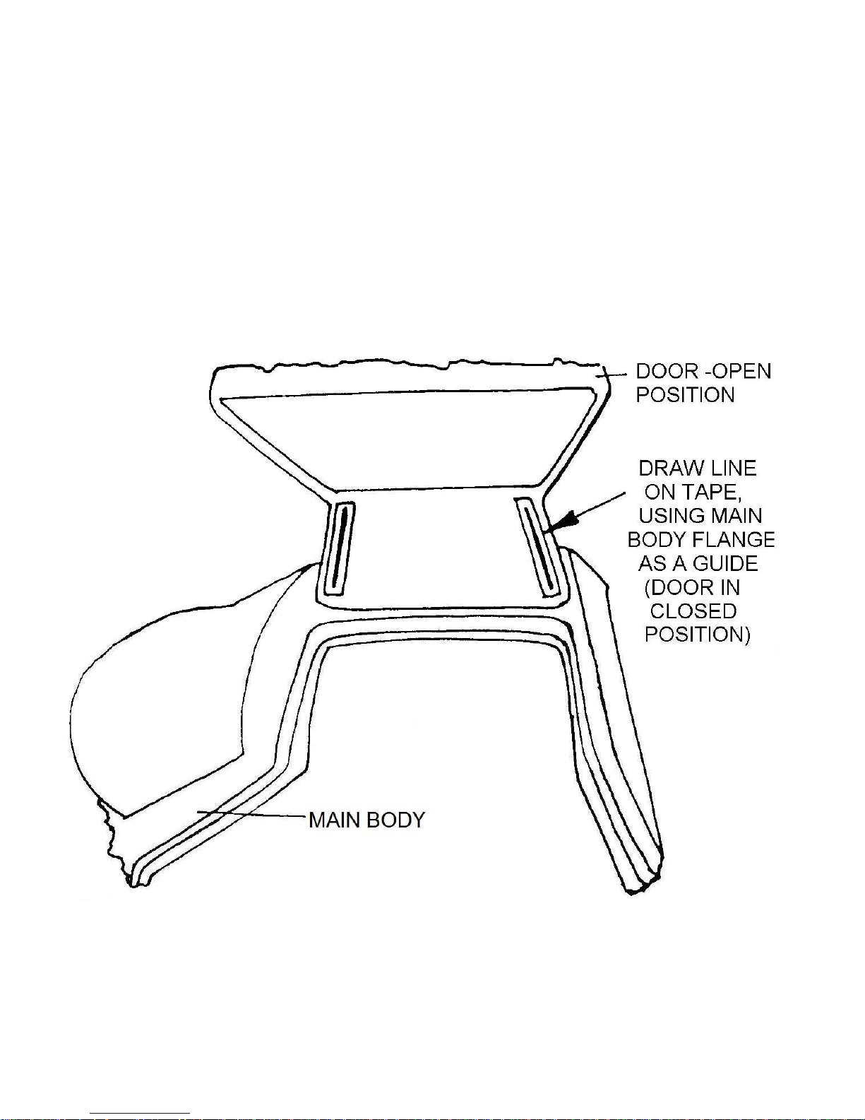
Using bolt kit #13, fasten the brackets to the inside of the flanges as in Figure 52B. Put strips of 1-1/2 inch
masking tape on the door ceiling next to the door flange. Close the door and draw a line on the tape along the main body
flange by reaching through the window opening as shown in Figure 52C. Draw these lines on both doors. Measure up
from the edge of the door flange 13-1/8 inches and draw a horizontal line. Next measure 2 inches in from the line just
drawn on the tape and make a vertical line. Locate the bracket by placing the face of the bracket with the single hole
upright and next to the line drawn 1-1/2 inches from the flange line marked on the tape as shown in Figure 53.The center
of the single hole should be even with the horizontal line marked on the door panel. The dimensions for locating the
bracket are shown in the illustration. After locating the bracket as described mark the two holes in the base of the bracket
and drill 3/16-inch holes at the marks. Try to drill holes only in the steel plates, not through the door skin. If you drill
through the door skin, the holes can be patched with body filler and sanded smooth. Now, tap the holes just drilled with a
¼ inch by 20 tap.
Fasten the brackets to the doors using bolt kit #14, as shown in Figure 53B. Bolt the door assist cylinder balls to
the mounted brackets as shown in Figure 53D. Then push the sockets of the cylinders over the balls and install the
locking clip. The large end of the assist cylinder should be attached to the main body as shown.
Figure 52C Locating Assist Cylinder Brackets – Door.
Page 50
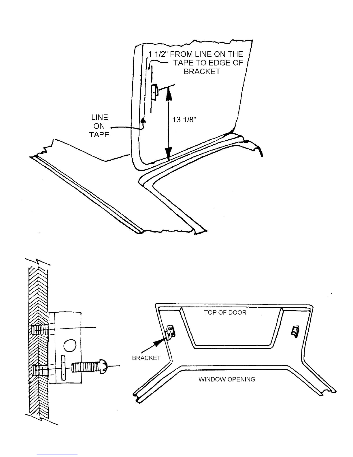
Figure 53A Position Bracket on Doors.
Figure 53B Detail: Mounting Assist Cylinder Brackets to Door.
Figure 53C Assist Cylinder Bracket Installed
Page 51
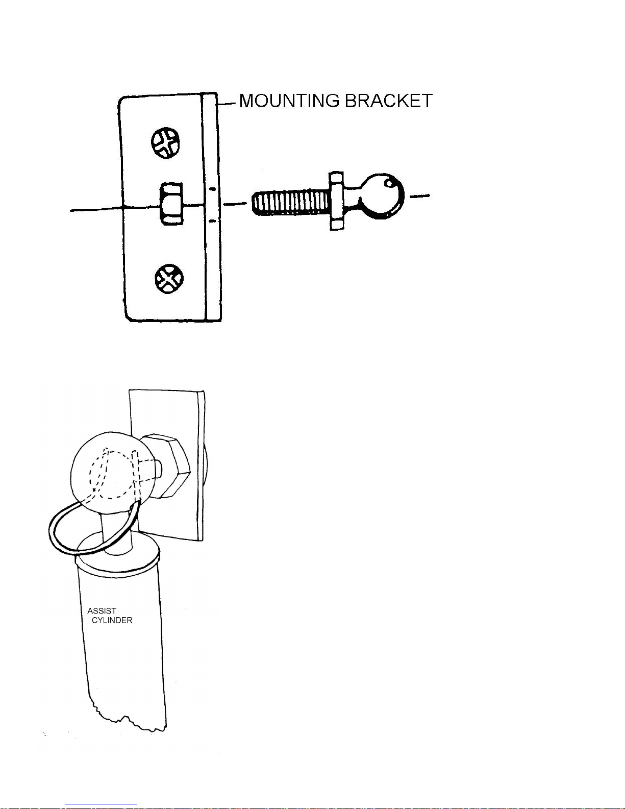
Figure 53D Detail: Assist Cylinder Ball Stud
Figure 53E Detail: Ball Stud and Safety Clip
Page 52
7. Installing the Door Latches
Tools Required 7/16 inch wrench
Socket Set
Parts Required Ff #Z731 Latch Plate
Ff #Z732 Remote Arm
Ff #Z726 Latch
Bolt Kit #15
Refer to Figure 54
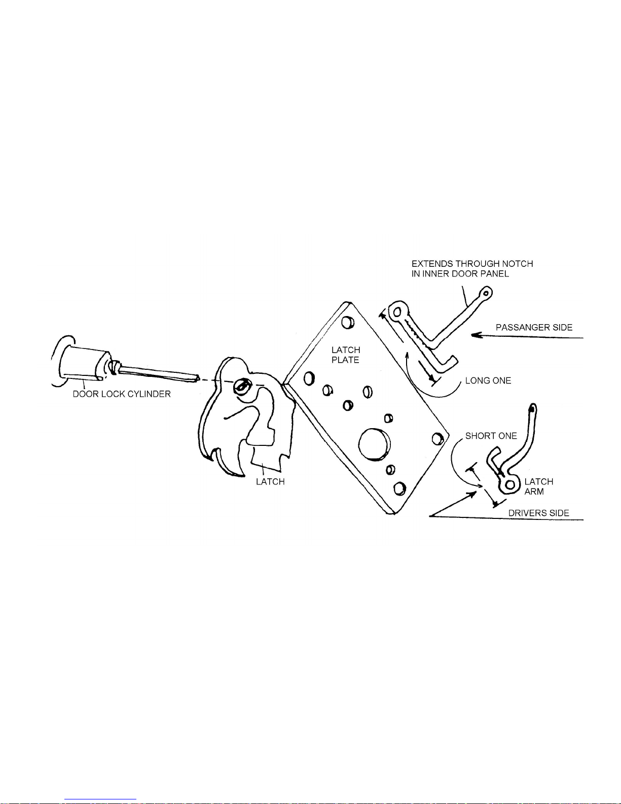
Attach the door latch to the latch plate with bolts in bolt kit #15. Bolt the plate to the door being certain the pin
from the outside lock cylinder fits in the slot in the latch as shown in Figure 54. Trim off the excess pin. Install the remote
arm by sliding the end into the slot cut at the top of the plate recess and bolt the arm to the latch as in Figure 54.
Figure 54 Door Latch Assembly
Page 53
8. Fitting the Striker Plate
Tools Required Drill
¼ inch drill bit
Jigsaw
Philips Screwdriver
Socket Set
Parts Required Ff #Z730 Striker Plates
Bolt Kit #16
Refer to Figure 55
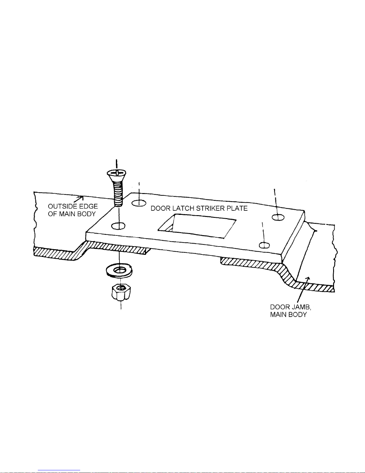
Locate the striker plate on the raised area of the doorjamb. Use the striker as a template to mark for bolt holes
and the portion of the door jamb to be removed under the striker plate. Drill ¼ inch holes, cut the door jamb for the striker
and bolt the plate to the door jamb using bolt kit #16 as shown in Figure 55. The door may be adjusted for proper fit. The
upper latch plate is slotted for up and down adjustment and the striker plate allows for sideways adjustment.
Figure 55 Latch Striker Plate
Page 54
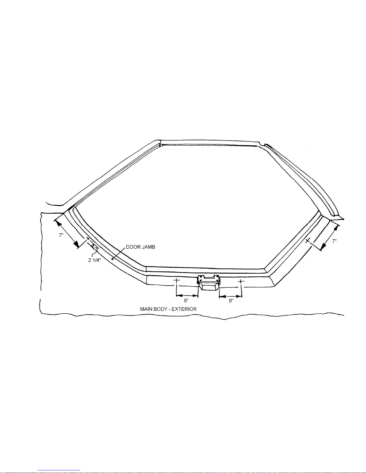
9. Installing the Door Stops
Tools Required Drill
5/16 inch drill bit
Two ½ inch wrenches
Parts Required Ff #Z755 Rubber Adjustment Stops
Bolt Kit #17
Refer to Figure 56
Using the 5/16-inch drill bit, drill 4 holes in each door jamb at the points indicated in Figure 56. Install the
doorstops so they fit snugly on the stops using bolt kit #17
Figure 56 Location of the Door
Stops.
Page 55
10. Preparing the Door for the Installation of the Side Glass
Tools Required Drill
5/16-inch drill bit
Rotary File or Rattail File
Refer to Figures 57 and 58
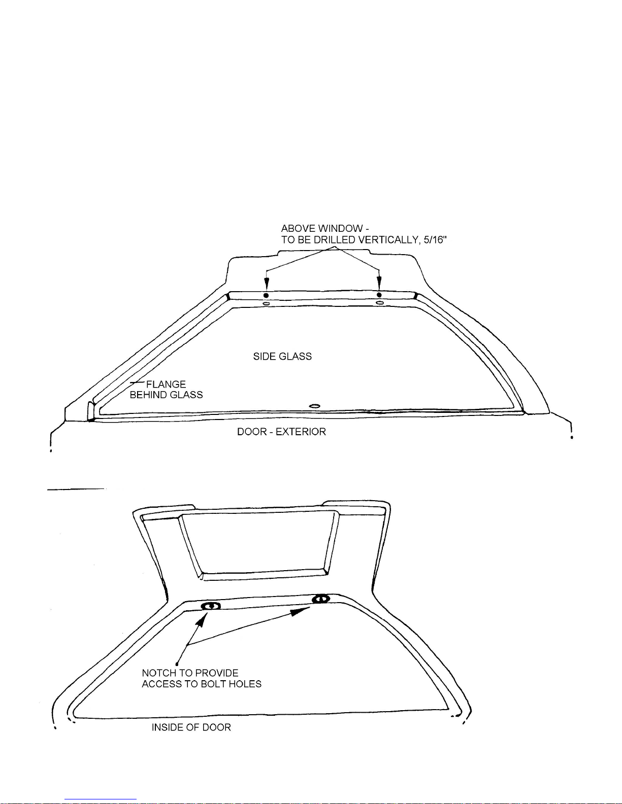
Place the glass in position of the window flange and center it in the opening. Mark the center line of each hole in
the glass on the door ABOVE the window. Remove the glass and drill a 5/16-inch hole on the marks as shown in Figure
57. This is where the glass hinge will attach to the door.
Working from inside the car, drill and notch an opening in the inner liner behind the hole just drilled as shown in
Figure 58. This will provide access to the end of the bolt that fastens the window glass hinge to the door.
Figure 57 Locating the Glass Hinge Mounting Holes
Figure 58 Notching Inner Liner
Page 56
11. Installing the Side Windows
Tools Required 7/16 inch wrench
Standard and Philips Screwdrivers
Parts Required Ff #Z741 Side Glass
Ff #Z745 Side Glass Latch and Hinge Kit
Bolt Kit #18
Refer to Figure 59 and 60
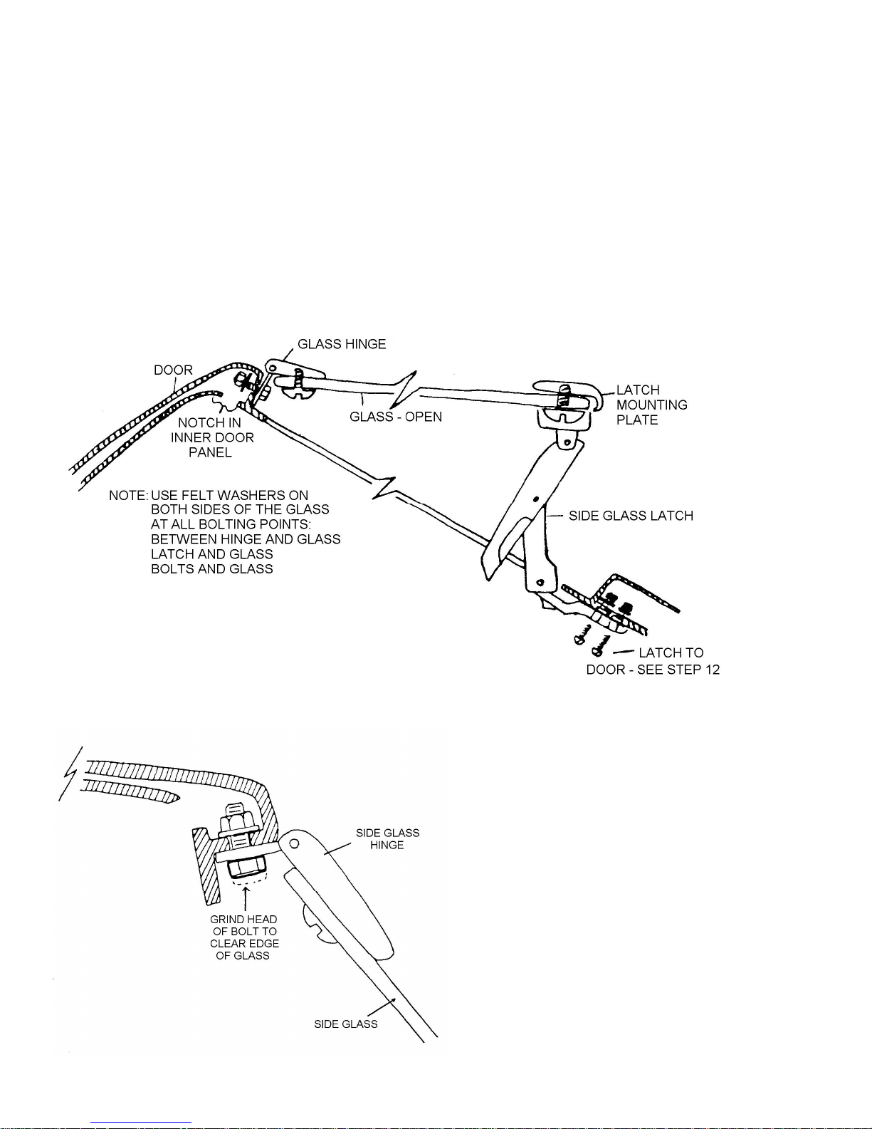
Install all hardware on the side glass as shown in Figure 59. Install the side glass in the window opening using
bolt kit #18. You may have to grind the bolt head to allow for clearance of the glass when the window is closed as in
Figure 60.
Figure 59 Latches and Hinge to Side Glass
Figure 60 Side Glass Hinge Mounting Bolt
Page 57
INSTALLING THE HEADLIGHT DIMMER SWITCH
Tools Required Drill
¼ inch drill bit
Socket Set
5/16-inch wrench
Parts Required Ff #X131 Dimmer Switch
Bolt Kit #20
Refer to Figures 63 and 64
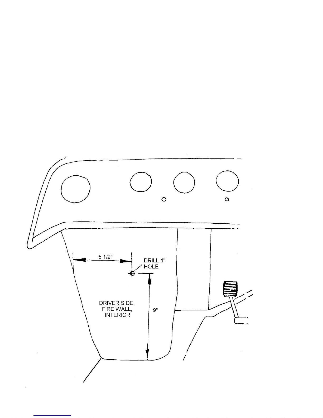
Locate the position for the dimmer switch according to Figure 63 and drill at this point using a 1 inch hole saw.
Insert the dimmer switch through the firewall and use the mounting plate of the switch to scribe the two mounting holes
onto the firewall. Drill using a ¼ inch drill bit. Again insert the dimmer switch into the firewall, the wiring connections
remaining on the front (exterior) of the wall and the movable switch on the interior of the wall. Bolt the switch into place
using bolt kit #20. Connect wires to the dimmer switch according to the wiring diagram.
Figure 63 Location of the Dimmer Switch
Page 58
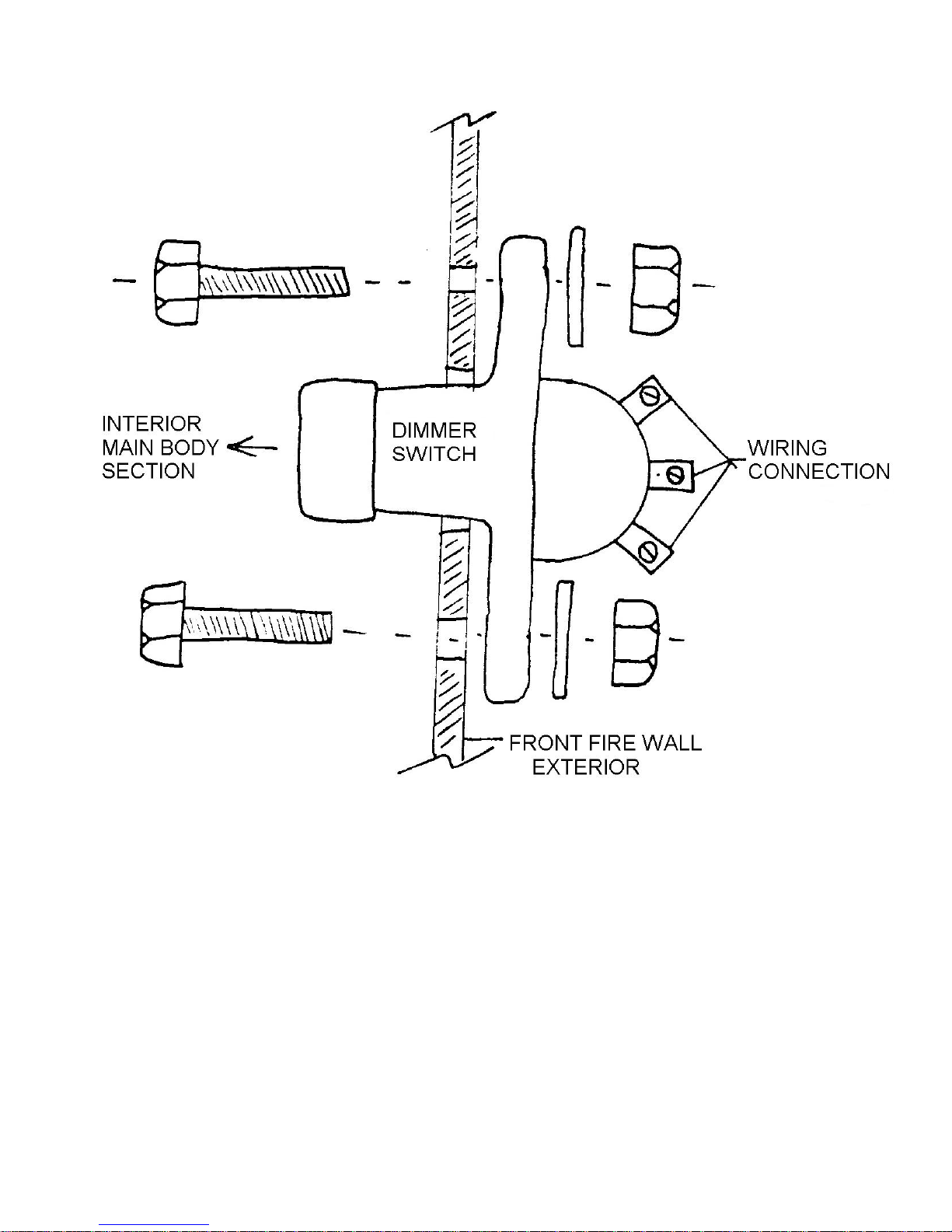
Figure 64 Detail: Mounting Dimmer Switch to Fire Wall
Page 59
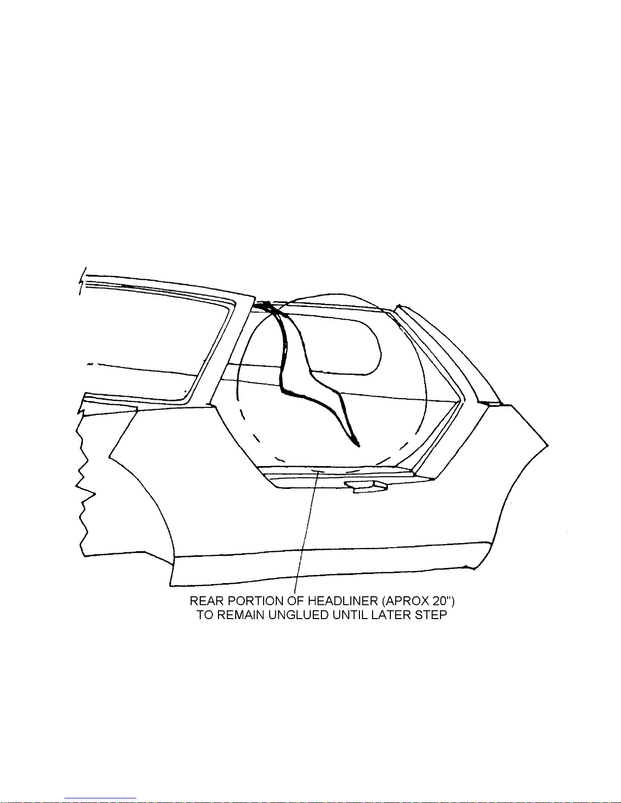
DETAILING THE INTERIOR
1. Installing Headliner
Tools Required 1-1/2 inch paint brush
Trim Knife
Parts Required Ff #MX194 Contact Cement
Ff #Z759L Headliner
Refer to Figures 65 through 70
Paint contact cement on headliner where headliner will meet the raised areas of the inner liner as shown in Figure
66. Do not apply cement to eh very rear edge of the headliner. This area must remain accessible for the installation of the
tail pins and adjuster stop. Cut a slot in the headliner for the overhead console wiring harness to be pulled through as
shown in Figure 66. Paint cement on the raised areas of the inner liner as shown in Figure 67.
Figure 65 Headliner
Page 60
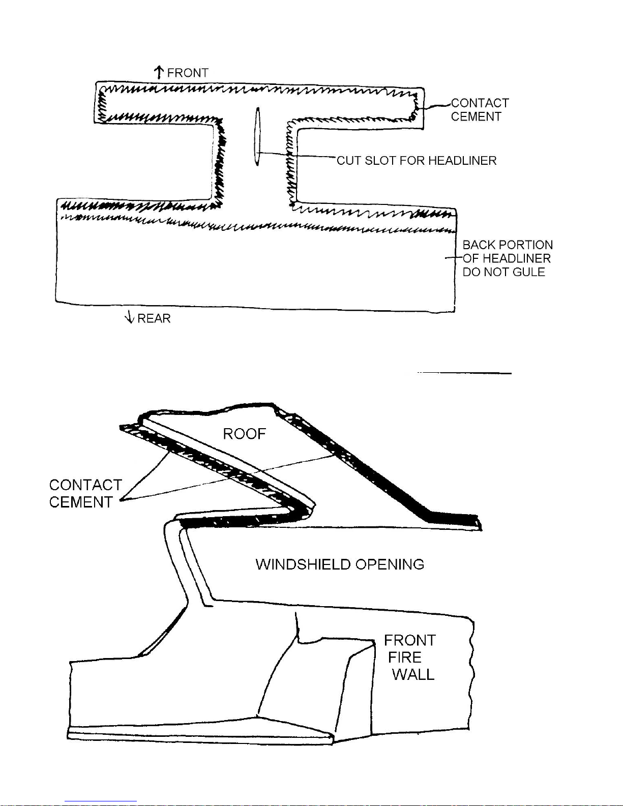
Figure 66 Headliner and Contact Cement
Figure 67 Contact Cement to Inner Liner
Page 61
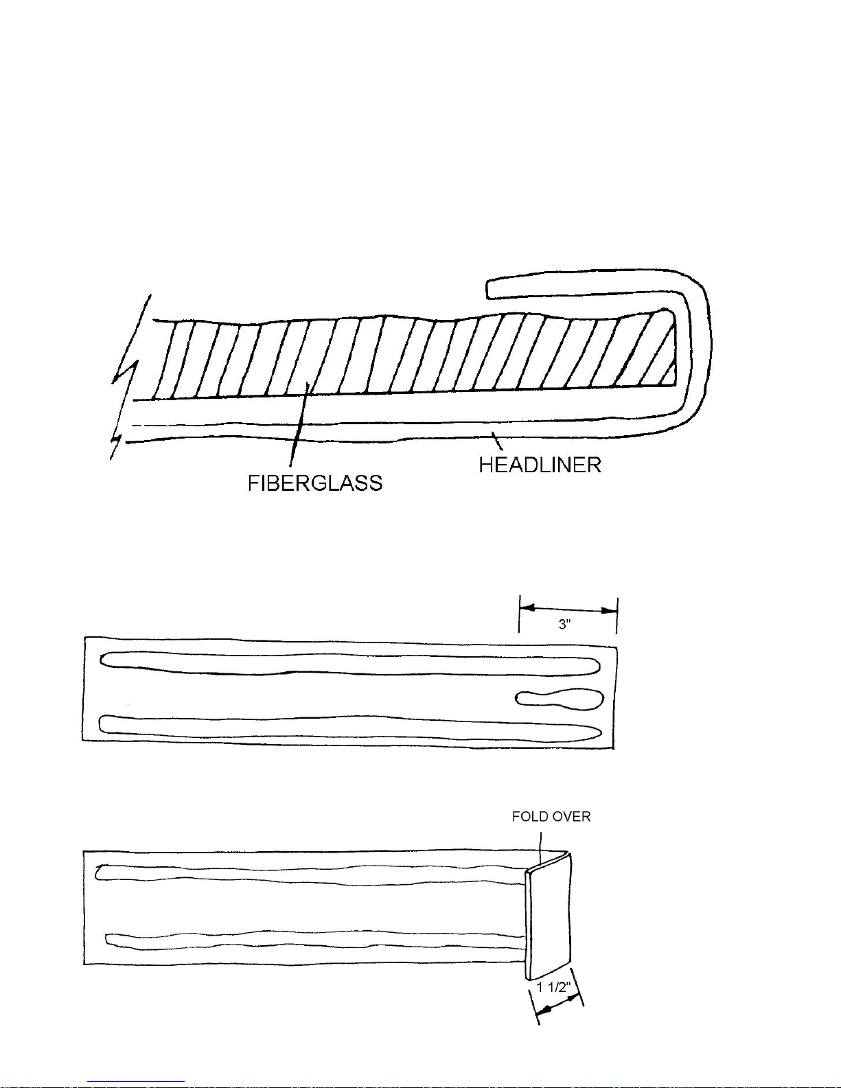
Allow the cement to dry and then press the headliner into place and pull the overhead wiring harness through the
slot cut. The edges of the headliner should be wrapped around the edges of the fiberglass as shown in Figure 68.
Paint cement on the windshield pillars. Paint cement in stripes on the pillar material with an additional stripe about
3 inches long on one end as shown in Figure 69. Allow cement to dry and fold that end over about 1-1/2 inches as
illustrated. This folded edge is installed where the pillar material meets the underside of the dash as in Figure 69. Place
the pillar material on the posts folding the edges around the edge of the fiberglass as described earlier. Paint cement on
the underside of the dash and the folded edge of the pillar material. Allow the cement to dry and put material in place as
shown in Figure 70.
Figure 68 Detail: Headliner Over Edge of Fiberglass
Figure 69 Headliner: Windshield Pillar Material.
Page 62
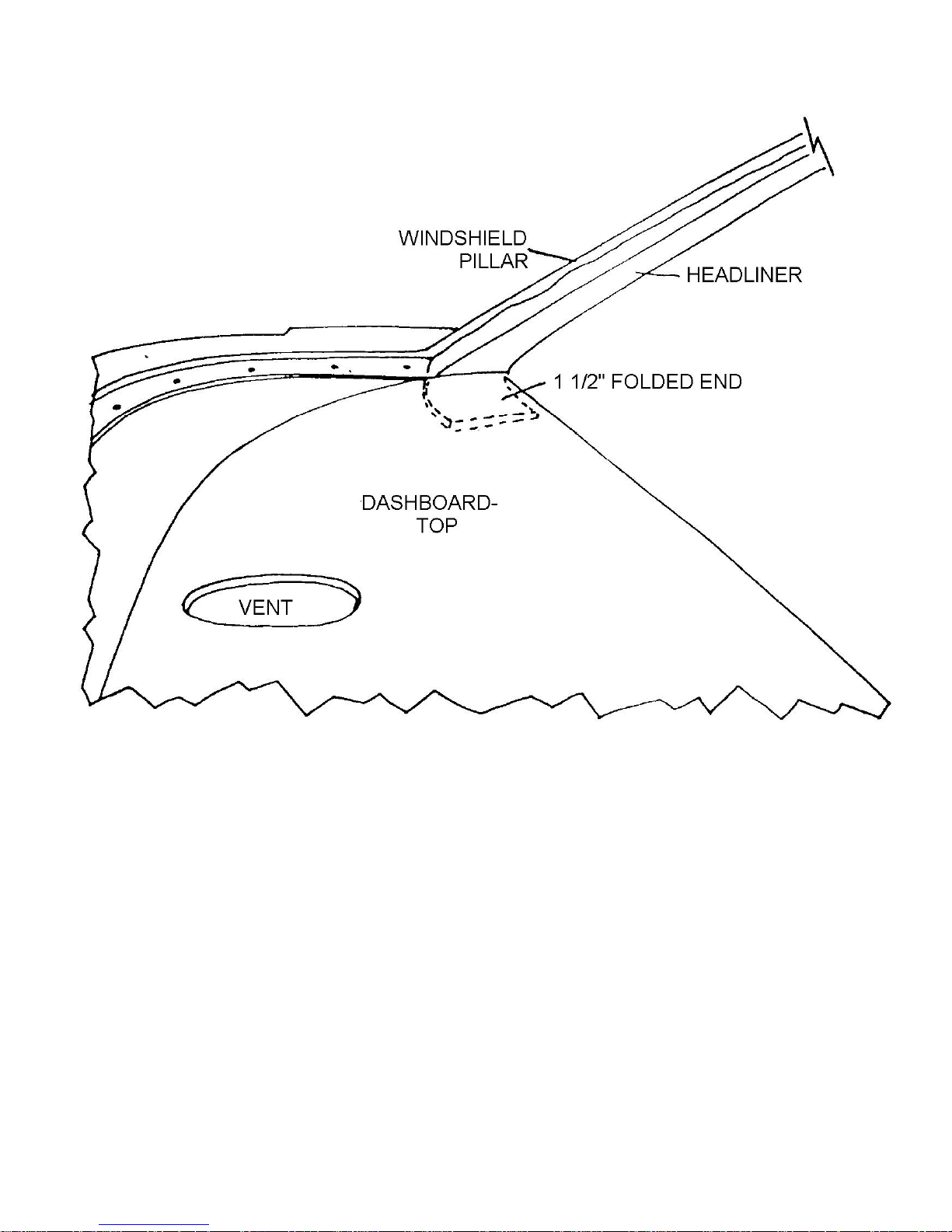
Figure 70 Headliner to Windshield Pillar
Page 63
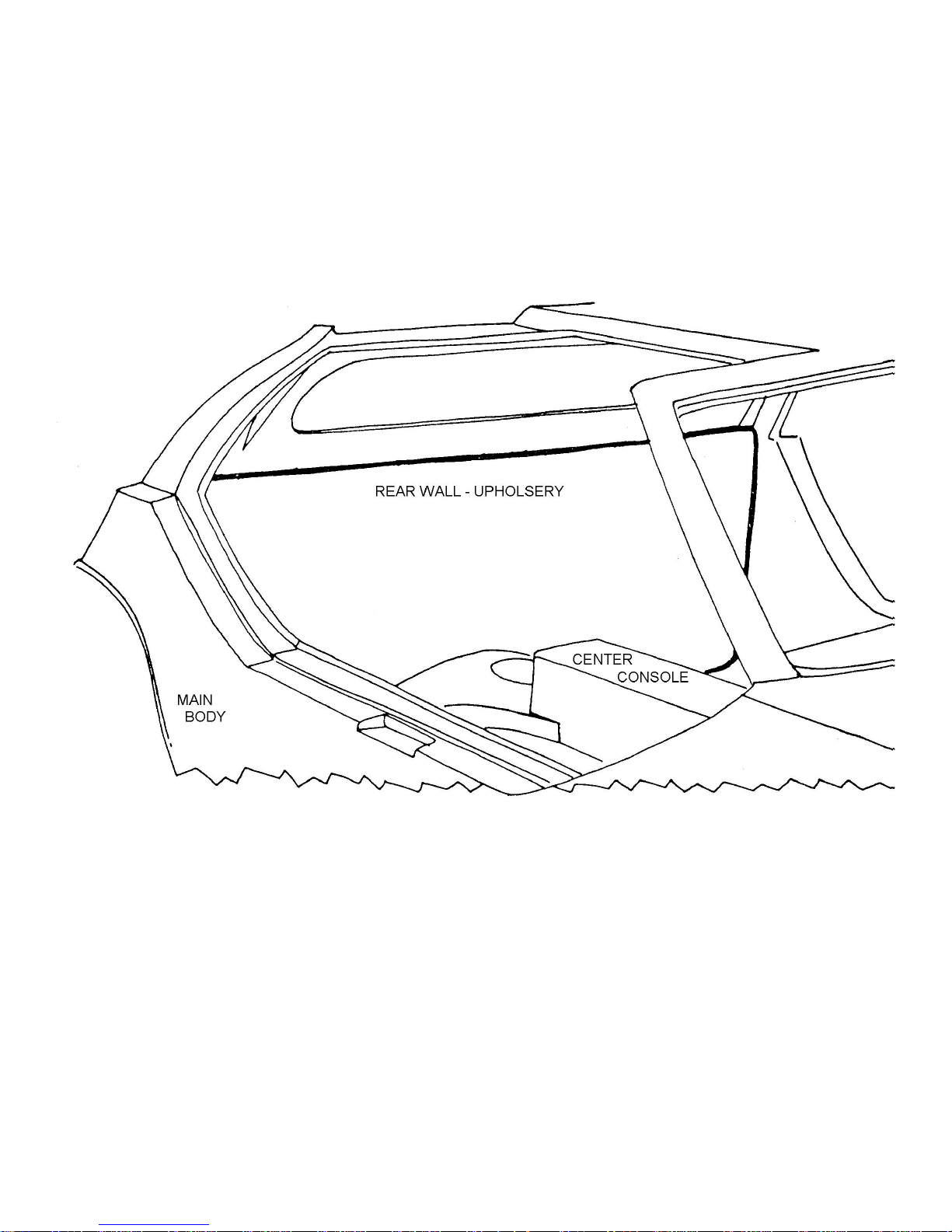
2. Installing the Firewall Upholstery
Tools Required Trim Knife
1-1/2 inch paintbrush
Parts Required Ff #MX194 Contact Cement
Ff #Z759A Rear Firewall Upholstery
Refer to Figure 71
Apply cement to rear firewall and upholstery and allow to dry. Press the upholstery into place as in Figure 71.
Figure 71 Rear Firewall Upholstery
Page 64
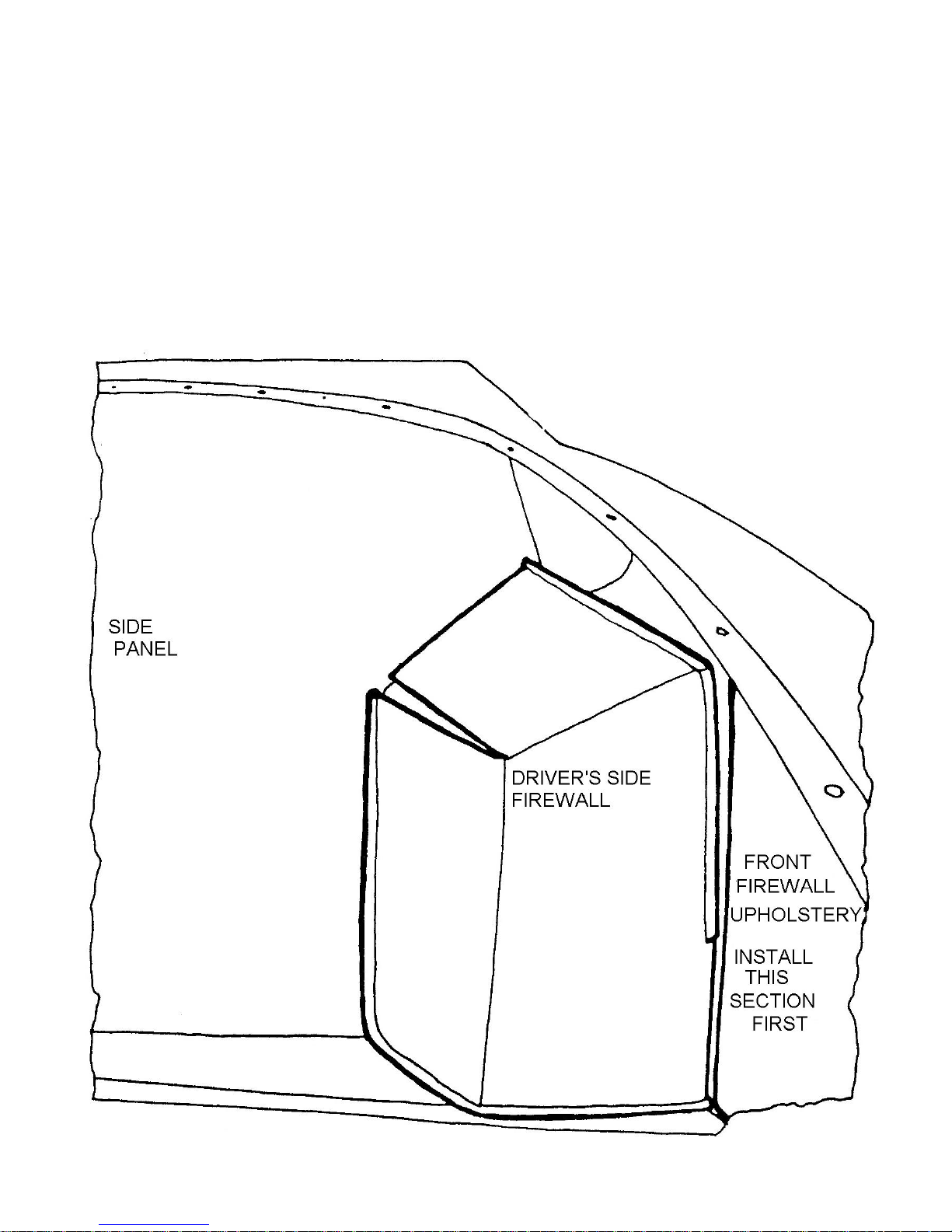
3. Installing Upholstery on Front Firewall
Tools Required Trim Knife
1-1/2 inch Paint Brush
Parts Required Ff #MX194 Contact Cement
Ff #Z759B Front Wall Upholstery
(Note: there are 3 pieces in this group)
Refer to Figure 72
Paint cement on the front firewall and all three pieces of upholstery and let the cement dry. Install the center
section first and then the sides. Holes must be cut in the material for the fuse box and dimmer switch.
Figure 72 Upholstery for Front Firewall
Page 65
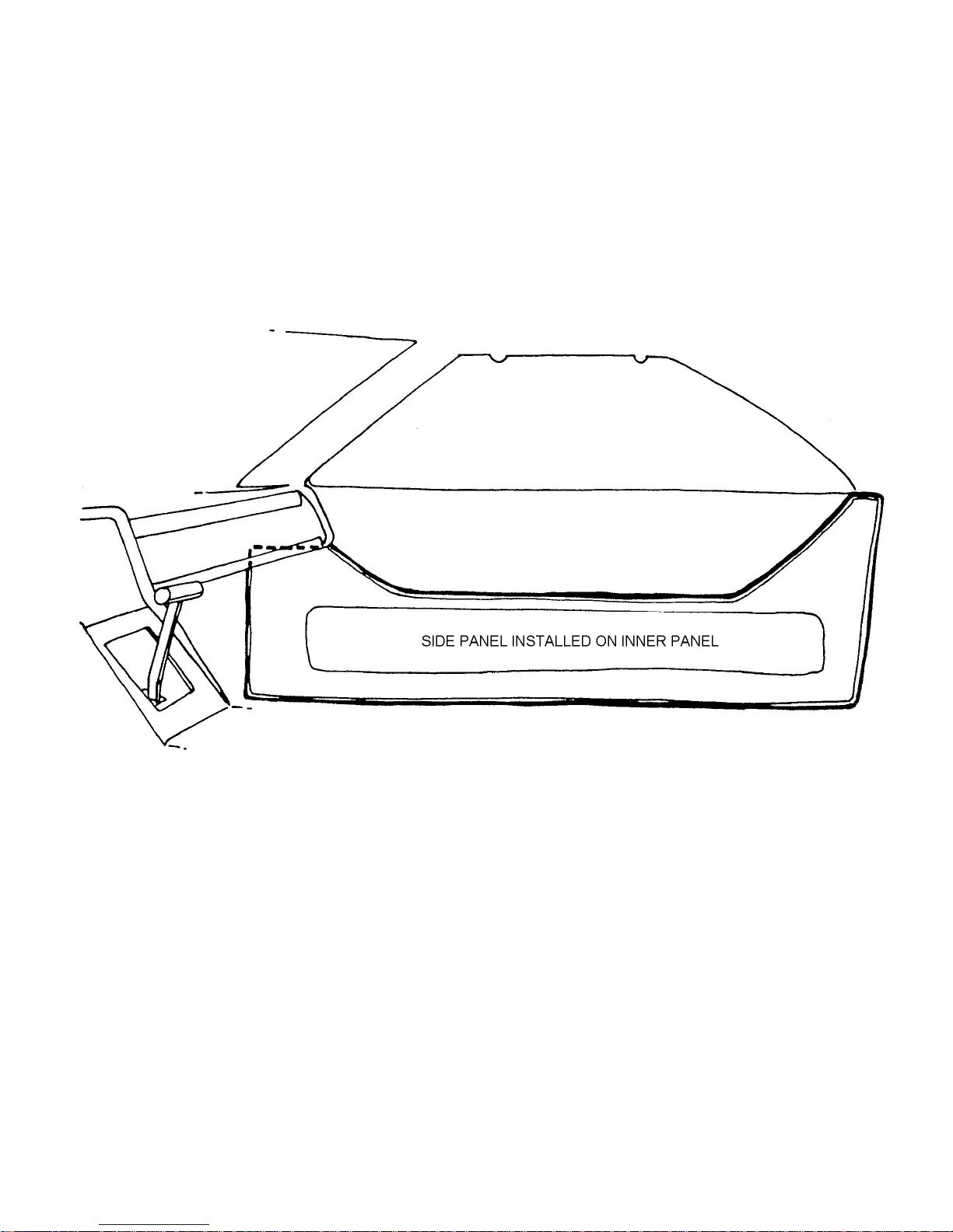
4. Installing Side Panels
Tools Required 1-1/2 inch paint brush
Parts Required Ff #MX194 Contact Cement
Ff #Z759C Side Panels
Refer to Figure 73
Apply cement to fiberglass where side panels will be installed. Paint cement on the side panels. Allow cement to
dry and press the panels into place.
Figure 73 Side Panels
Page 66
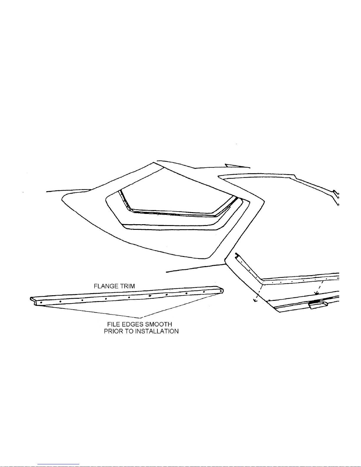
5. Installing Door Flange Trim
Tools Required Drill
1/16 inch Drill Bit
Philips Screwdriver
Hacksaw
Fine Tooth File
Parts Required Ff #Z707 Flange Trim
Bolt Kit #21
Refer to Figure 74
Measure the doorjamb and cut a length of trim to fit. Smooth the edges with a fine file. Bend the trim as necessary
to fit. Drill holes in the fiberglass using the holes in the trim as a guide with the 1/16-inch drill bit. Fasting the trim using bolt
kit #21
Figure 74 Door Flange Trim
Page 67
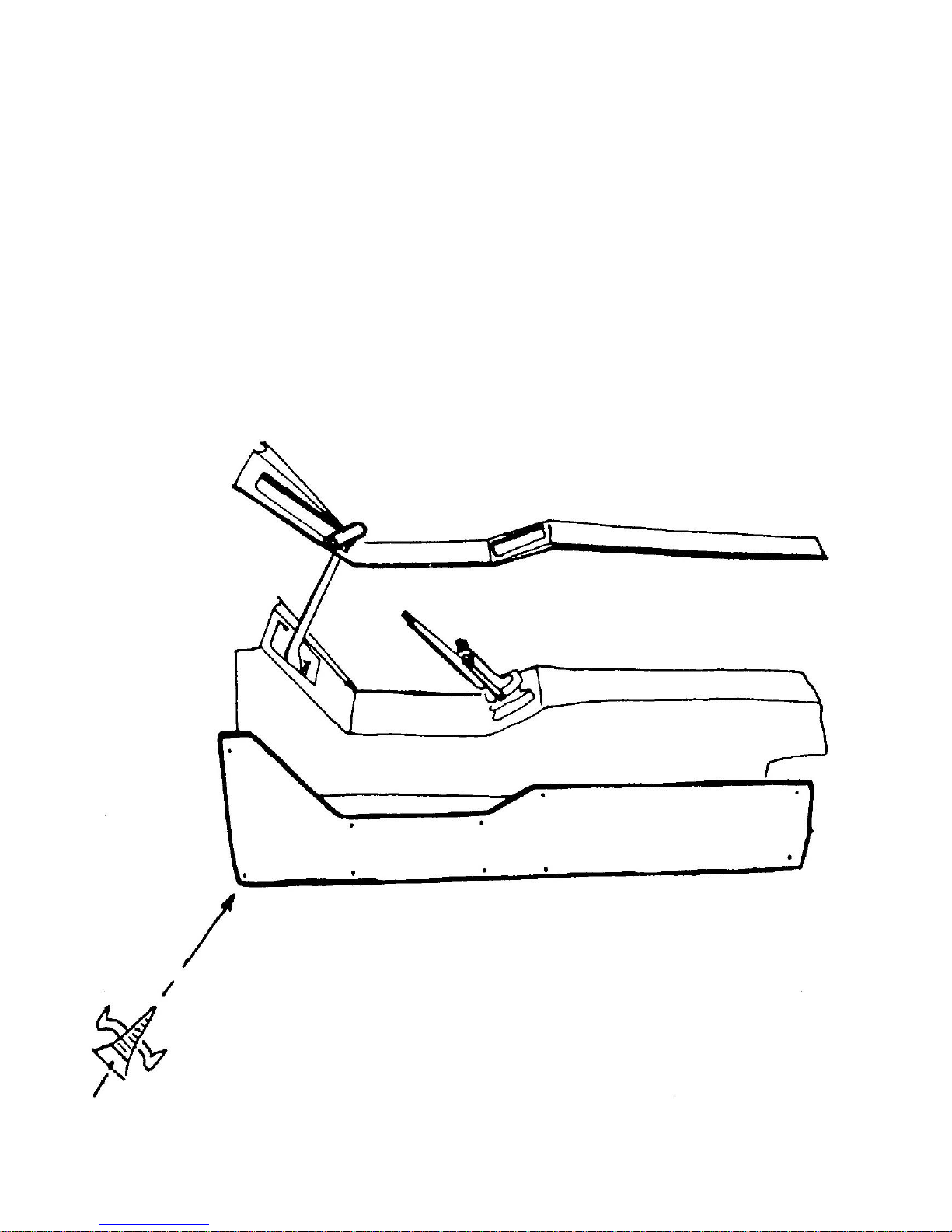
6. Upholstering Center Console
Tools Required Trim Knife
1-1/2 inch Paint Brush
Drill
1/16 inch Drill Bit
Philips Screwdriver
Parts Required Ff #Z759D Center Console Upholstery
Ff #MX194 Contact Cement
Bolt Kit #22
Refer to Figure 75
Apply contact cement to sides of console and material that covers the side. Press material in place after the
cement has dried. Install the center piece as shown using bolt kit #22
Figure 75 Upholstery to
Console
Note: One-piece type console cover to be installed in the same manner without the trim screws on the top section.
Page 68
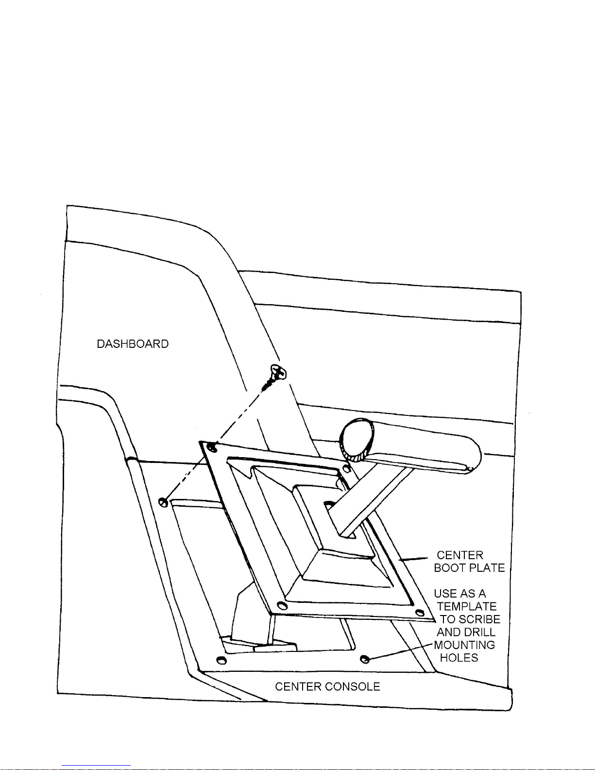
7. Installing Shifter Boot
Tools Required Drill
1/8 inch Drill Bit
Screwdriver
Parts Required Ff #X120 Shifter Boot
Refer to Figure 76
Install the shifter boot over the lever. Use the cover as a template for drilling 4 1/8 inch holes as shown in Figure
76. Fasten the boot and cover in place using the screws in the shifter kit.
Figure 76 Installing Shifter Boot.
Page 69
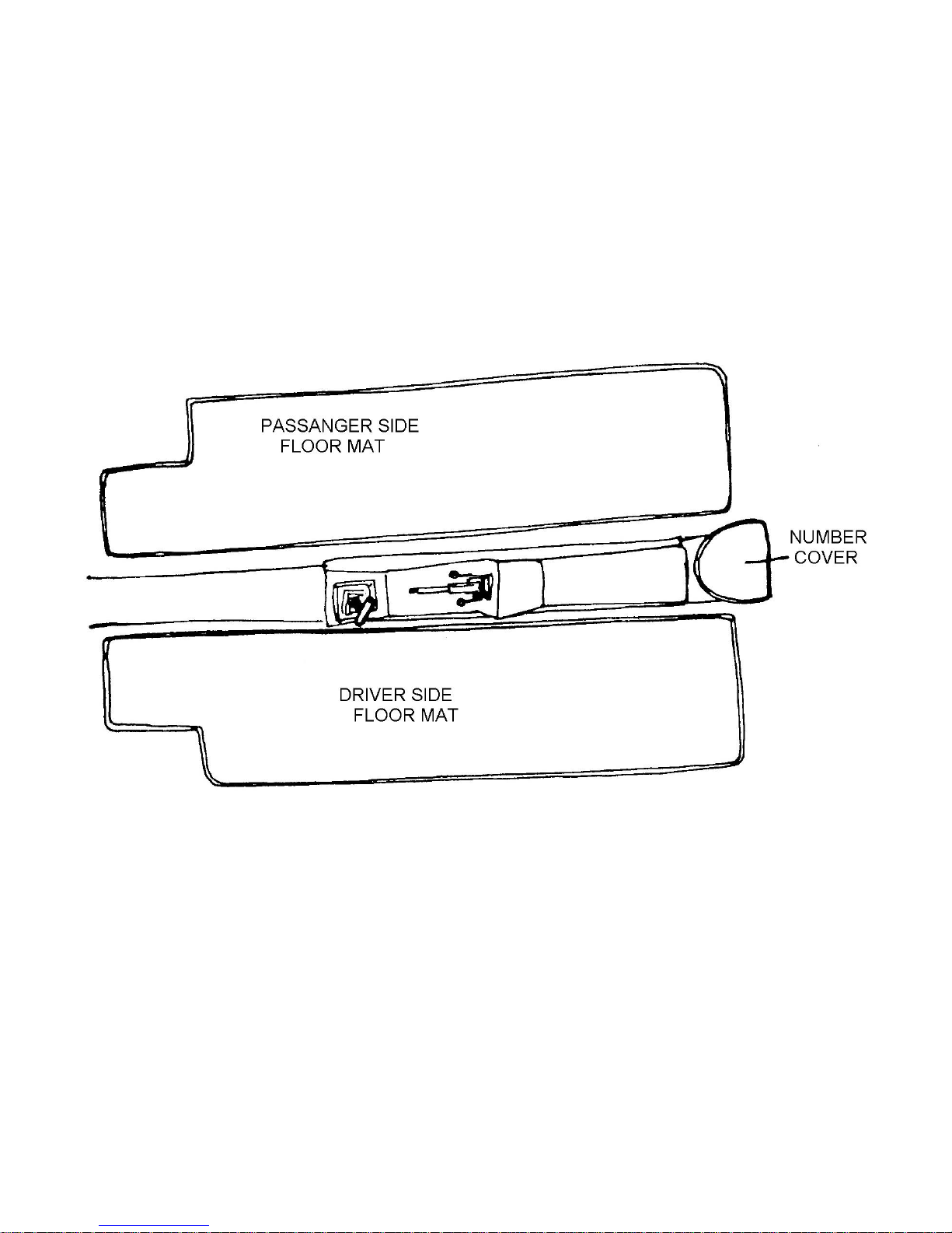
8. Installing Floor Mats
Tools Required Trim Knife
1-1/2 inch Paint Brush
Parts Required Ff #MX194 Contact Cement
Ff #Z759E Floor Mats
Refer to Figure 77
Cement the floor mats in place using the procedure for cementing upholstery described in previous operations.
Install the number cover in the same manner. Note: You may not want to cement the number cover in place yet as access
to chassis numbers may be necessary to register your completed Aztec 7.
Figure 77 Installing Floor Mats
Page 70
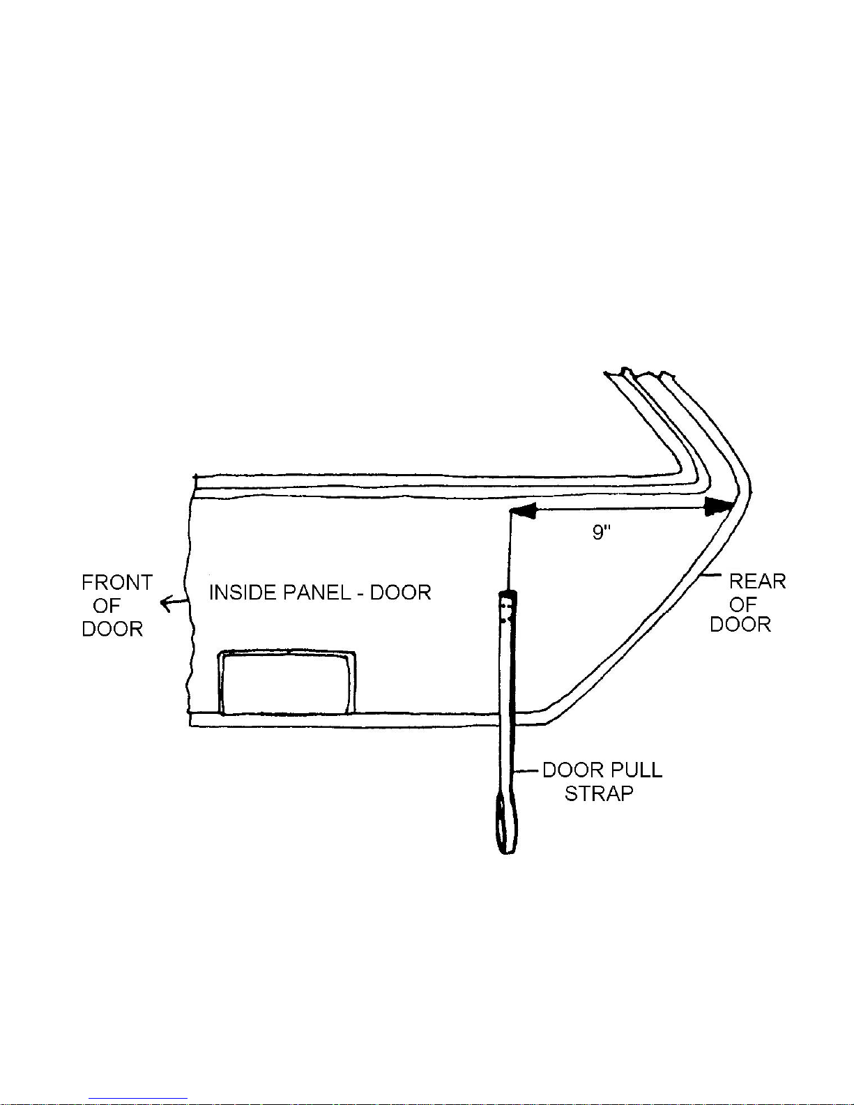
9. Installing Door Panels
Tools Required Pliers
Drill
1/16 inch Drill Bit
Philips Screwdriver
Parts Required Ff #Z759F Door Panels
Ff #Z759G Door Panel Pull straps
Bolt Kit #23
Refer to Figures 78, 79 and 80
Attach the pull strap to the inner panel of the door with 4 screws from bolt kit #23, as in Figure 78. Fasten the ‘S’
hook to the latch arm as shown and squeeze the hook closed with the pliers. Install the door panels by drilling holes
through the panel and door liner at points shown in Figure 80. Fasten the panel to the door with trim screws in bolt kit #23.
Figure 78 Door Pull Strap
Page 71
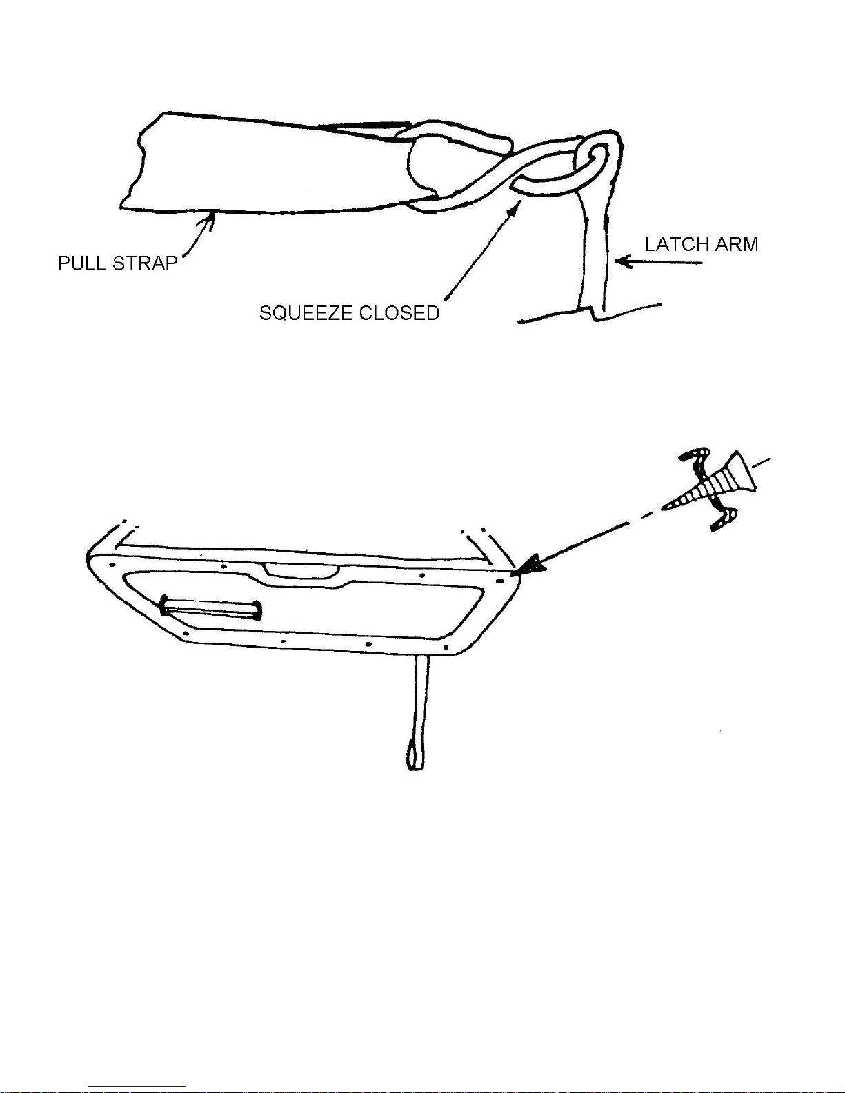
Figure 79 Door Pull Strap to Latch Arm
Figure 80 Attaching Door Panel
Page 72
10. Installing Heater Vents
Tools Required Drill
2 inch Hole Saw
Socket Set
Parts Required Ff #X181 Heater Vent Parts
Refer to Figures 83 and 84
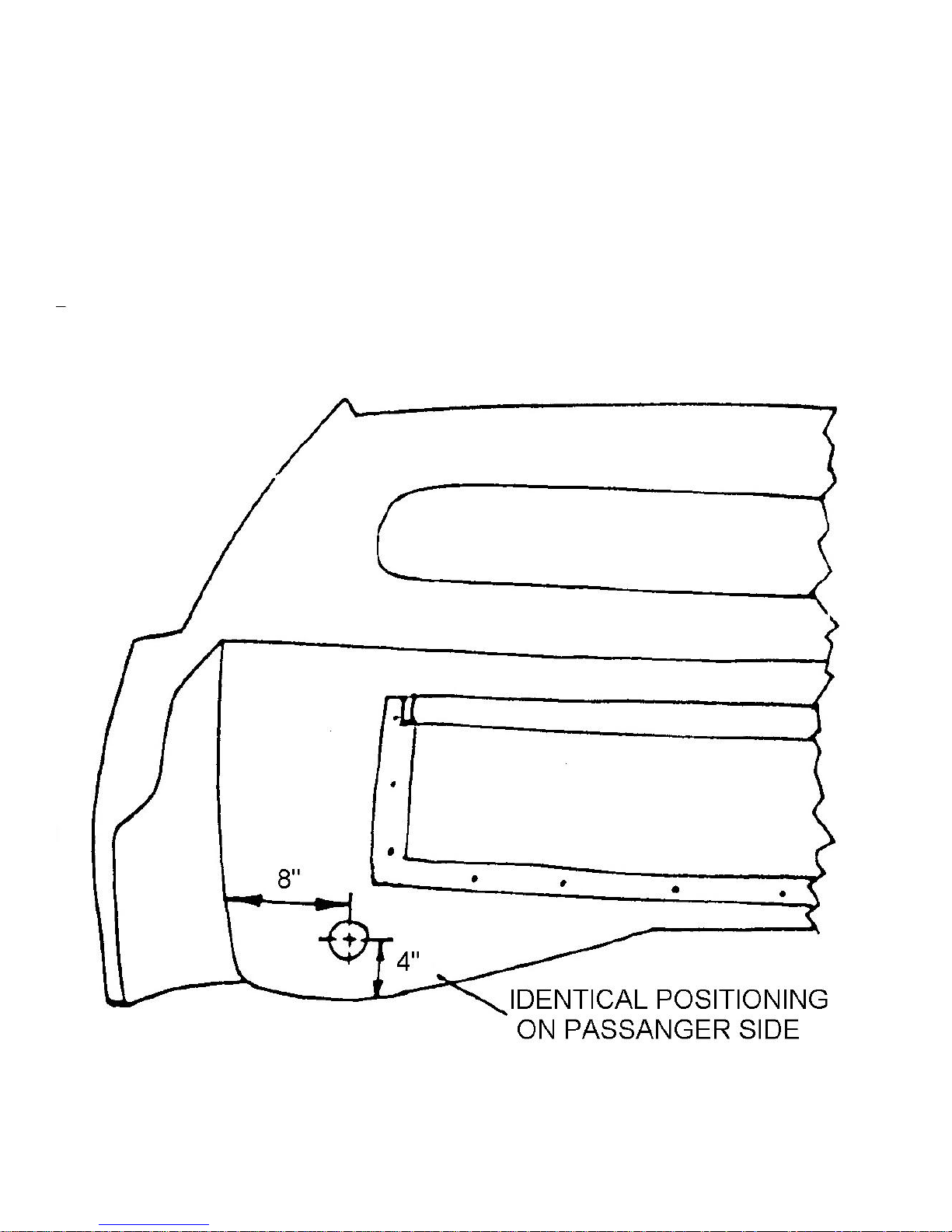
Measure the outside of the rear firewall and cut 2-inch holes as indicated by Figure 83. Install the heater vent
outlets as shown in Figure 84. Attach the hose from the heat exchanger to the outlet.
Figure 83 Locating Heater Vents
Page 73
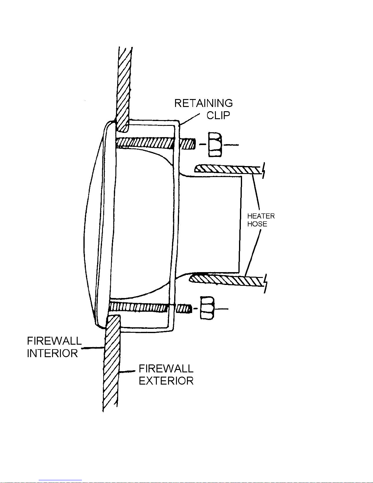
Figure 84 Installing Heater Vents and Heater Hose
Page 74
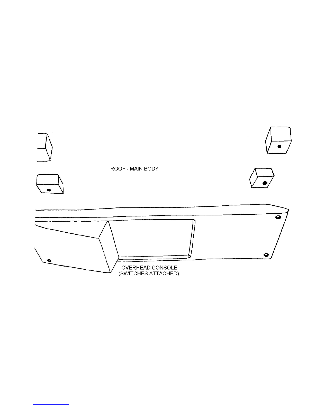
11. Installing the Overhead Console
Parts Required Drill
3/16 inch Drill Bit
1/8 inch Drill Bit
Philips Screwdriver
Parts Required Bolt Kit #25
Refer to Figure 85
Connect the overhead wiring harness to the overhead console per the instructions with the wiring kit. Drill four
3/16-inch holes as shown in Figure 85. Place the console in place and mark the molded plates in the roof through the
holes in the console. Remove the console and drill these marks with a 1/8-inch drill bit. Fasten the console in place using
bolt kit #25.
Figure 85 Installing Overhead Console
Page 75
12. Installing the Steering Shaft
Tools Required Drill
5/16 inch Drill Bit
¼ inch Drill Bit
2 inch Hole Saw
Jigsaw
Socket Set
Pliers
Screwdriver
½ inch wrench
Flat File
String
Parts Required Bolt Kit #26
Ff #Z785 Steering Column Upper Support
Ff #Z786 Steering Column Lower Support
VW Steering Column
Refer to Figures 86 through 94
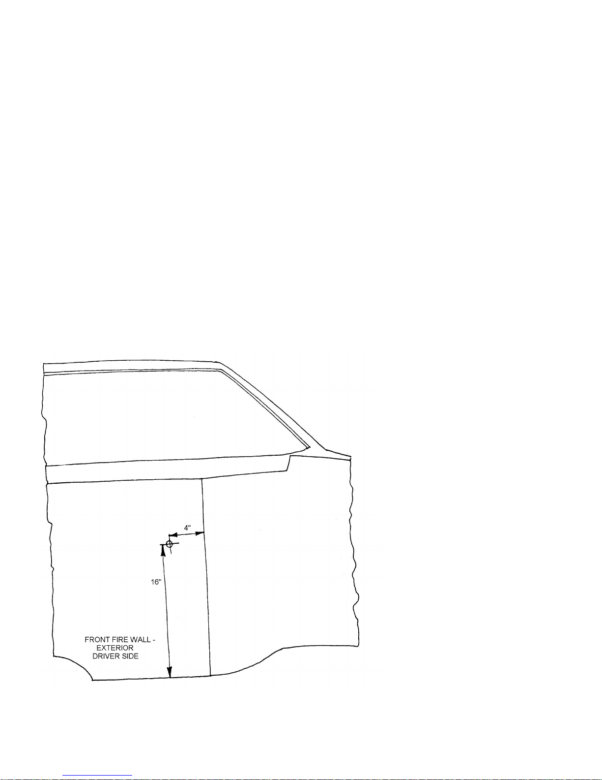
Drill a ¼ inch hole in the front firewall at the point shown in Figure 86. Place the car on jack stands and remove
the left front wheel. Thread a piece of string through the ¼ inch hole and line it up with the center of the steering box and
the center of the hole in the dashboard for the steering column. Pull the string tight and check to see if it is straight. If not,
notch the ¼ inch hole in the firewall until it is. Once the string is straight, that point will be the center for the 2-inch hole
you must now drill.
Figure 86 Locating Steering Column Hole
Remove the steering shaft from the column housing by removing the circlip at end of the shaft as in Figure 87.
Slide the column off the shaft.
Page 76
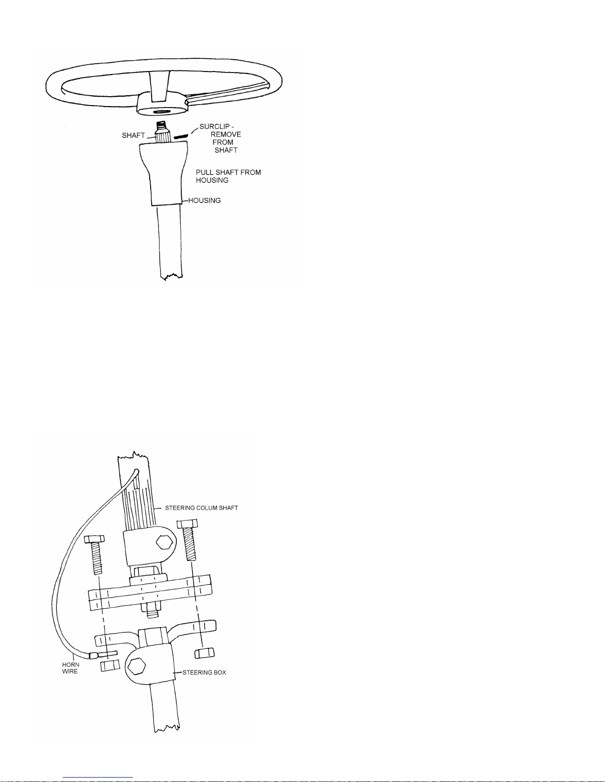
Figure 87 Steering Column and Shaft
Slide the steering shaft through the dash and the flange. Slip the column housing over the steering shaft through
the hole in the dash and into the flange. Refit the column on the steering shaft. Connect the steering shaft to the steering
box as in Figure 88.
Center the steering shaft and the flange and drill two 5/16 inch holes. Bolt the assembly together as shown in
Figure 89 using bolt kit #26.
Install the steel plate to the steering column using the clamp in bolt kit #26. Do not tighten the clamp yet. Fasten
the steel plate to the dash by drilling two 5/16 inch holes using the plate as a guide. Fasten the plate to the dash using bolt
kit #26 as shown in Figure 90. Tighten the clap around the column.
Figure 88 Steering Shaft to Steering Box
Page 77
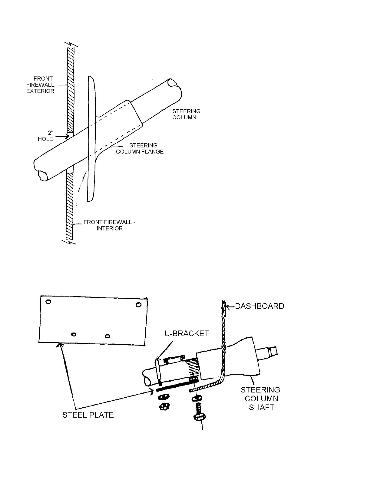
Figure 89 Steering Column Flange
Figure 90 Steering Column Support
Page 78
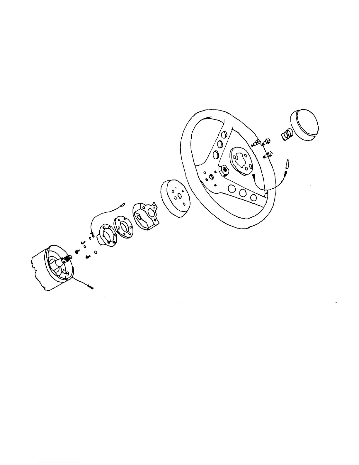
13. Installing the Steering Wheel
Tools Required Socket Set
Parts Required Horn Wire
Ff #X157 Adapter Kit
Ff #X155 Steering Wheel
Refer to the Instructions included with the steering column adapter, steering wheel kit and Figures 93 and 94
Figure 93 Steering Column Adaptors and Steering Wheel
Page 79

14. missing
Page 80
15. Installing the Rear Glass
Tools Required Knife
Silicone Lubricant
Dull Screwdriver
Parts Required Ff #Z743 Rubber Glass Gasket
Ff #Z742 Rear Window
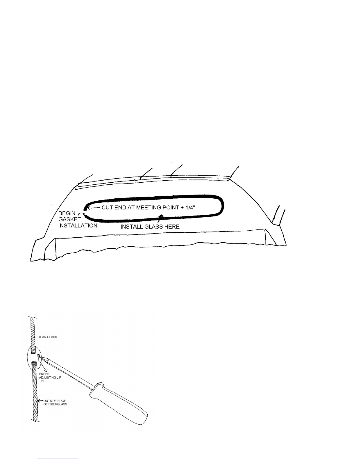
Refer to Figures 96, 97 and 98
Trim the rear section of the headliner material flush with the edge of the fiberglass as shown in Figure 96.
Figure 96 Rear Glass Gasket Installation
Place the rubber gasket in the window opening starting at one side and running the gasket all the way around.
Trim the end of the gasket off about ¼ inch longer than necessary as shown in Figure 97. Make certain the connecting lip
of the gasket is on the outside of the car.
Figure 97 Rear Glass Installation – Gasket
Insert the glass in the channel of the gasket at one corner and work the glass into the gasket channel all the way
around the window opening with a dull screwdriver blade. Once the glass is in place, push the connecting lip in place with
the screwdriver as shown in Figure 98.
Figure 98 Rear Glass Installation – Gasket Adjustment
Page 81
16. Installing the Windshield
Tools Required Knife
¾ inch Masking Tape
Car Wax
Caulking Gun
Parts Required Ff #MX193 Silicone
Ff #X100 Butyl Tape
Ff #Z740 Windshield
Ff #X137 Paint
Trim the headliner back to approximately ½ inch from the edge of the windshield opening as shown in Figure 99.
Figure 99 Headliner Over Windshield Opening Flange
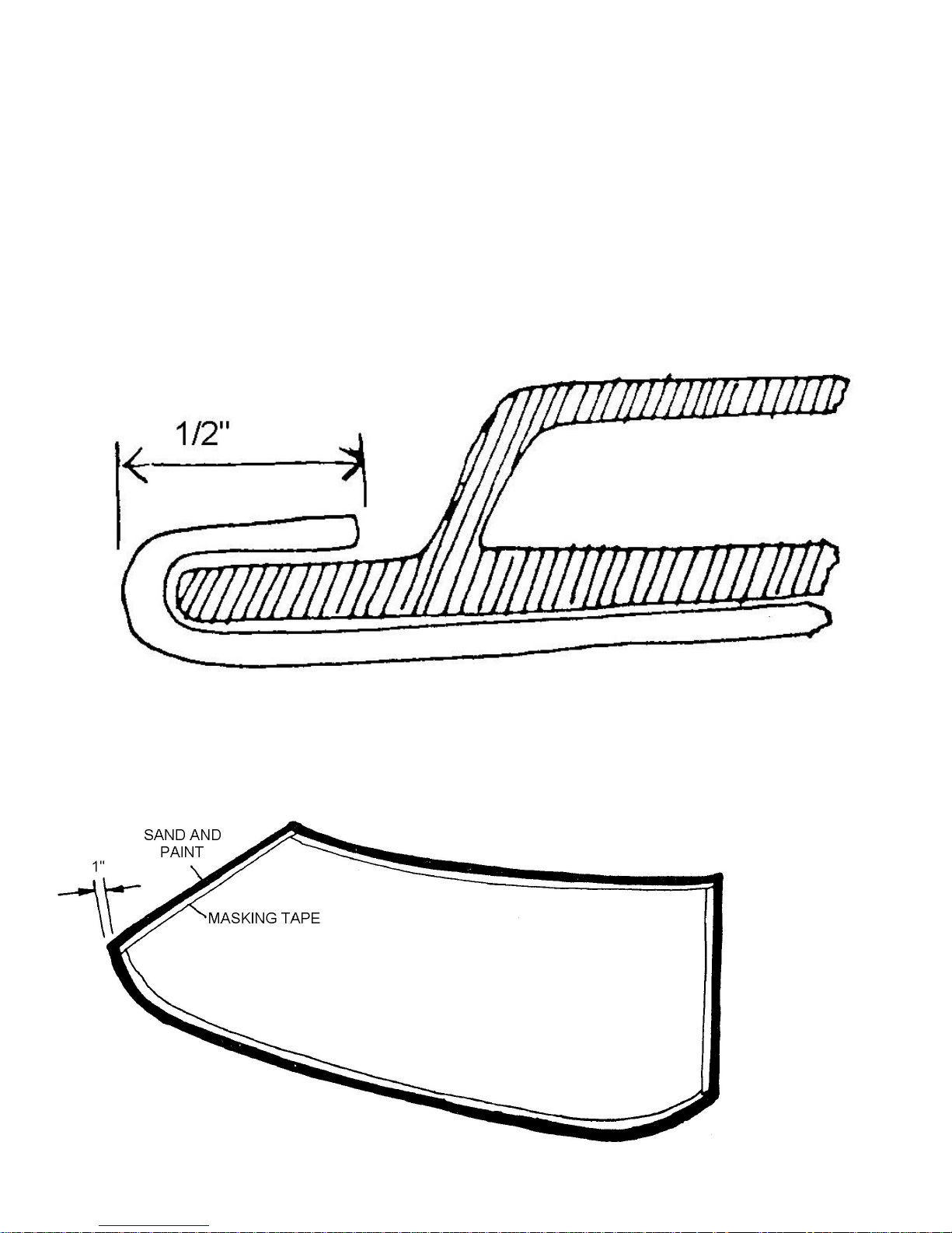
Mask the edge of the windshield inside to allow approximately 1 inch of exposed glass along the perimeter of the
windshield. The area in black in Figure 100 shows the part of the glass not taped. Spray this area with flat black paint.
Figure 100 Windshield Preparation
Page 82
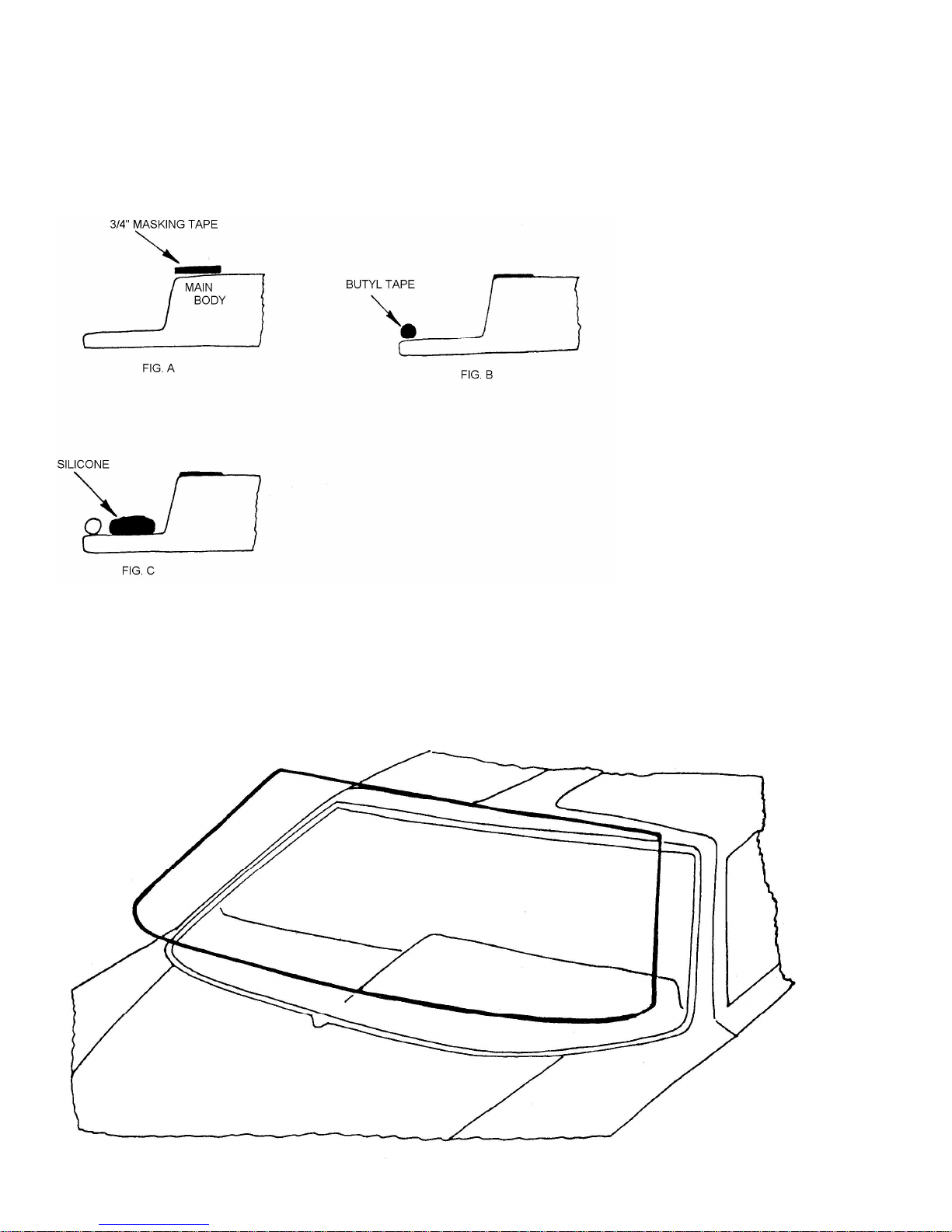
Apply commercial car wax to the outside of the windshield about 3 inches around the edge. Do not buff out the
wax. Tape the main body around the windshield area with ¾ inch tape as shown in Figure 101. Press butyl tape around
the edge of the windshield opening as in Figure 101.
Run a bead of silicone between the butyl tape and the corner of the windshield flange as shown in Figure 101.
Leave a space of about 1/16 of an inch between the butyl tape and the silicone. You must work quickly now, before the
silicone sets.
Figure 101 Windshield Installation – Body Preparation
With the aid of an assistant, lift the windshield into place and position it evenly on the windshield flange as shown
in Figure 102. Make certain the windshield rests only on the flange, not the main body. This can be insured by placing two
pieces of rubber once in place and run a second bead of silicone around the glass to fill any spaces between the glass
and the body. When this application of silicone has partly set, dip your finger in dish detergent and smooth the surface of
the silicone. Remove the masking tape and clean wax off the glass when the silicone is completely set.
Figure 102 – Installing Windshield Glass
Page 83
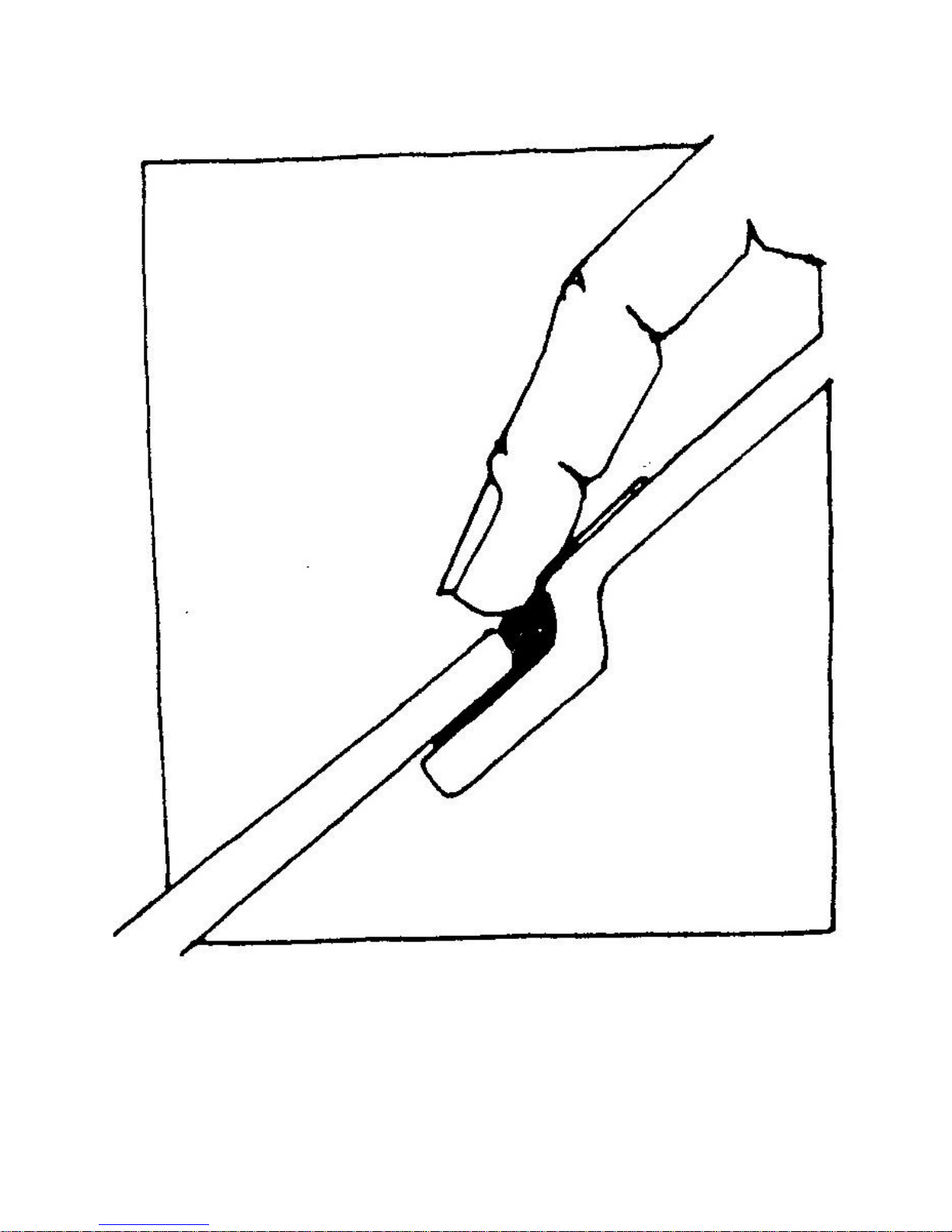
Figure 103 Detail: Smooth Silicone Along Edge of Windshield
Page 84
17. Installing the Seats
Tools Required Drill
5/16 inch Drill Bit
Socket Set
½ inch Wrench
Chalk
1-1/2 inch Paint Brush
40 Grit Sandpaper
Parts Required Ff #X127 Seat Rails
Ff #Z781 Seat Brackets
Ff #Z759H Seat Back Rugs
Ff #Z759I Seat Covers
Ff #MX194 Contact Cement
Bolt Kit #27
Bolt Kit #28
Refer to Figures 104 through 110
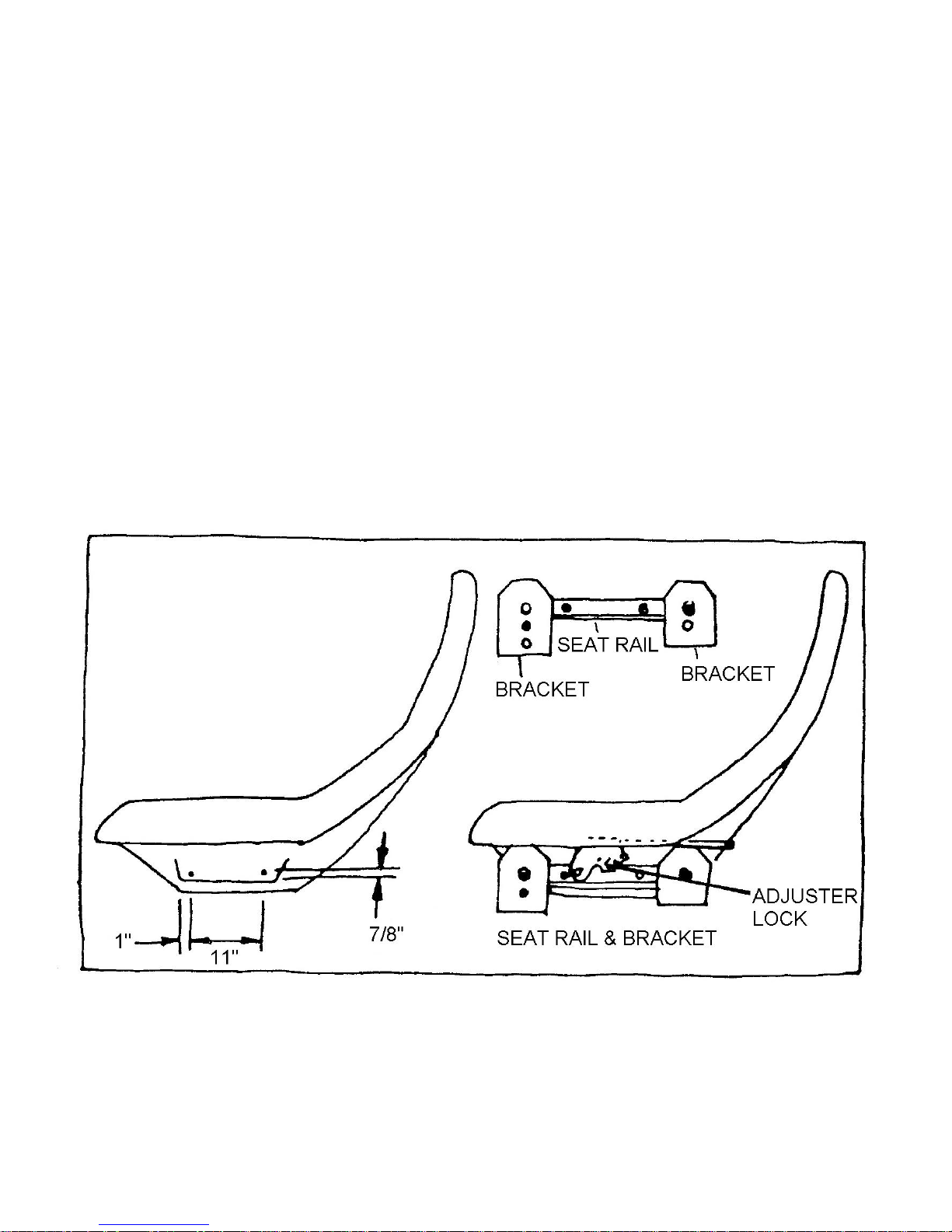
Sand all seat edges smooth and round with 40 grit sandpaper. Mark and drill four 5/16-inch holes at points
indicated in Figure 104. Attach the seat adjuster to the seat rails using bolt kit #27. Fasten the seat rail with the adjuster
lock to the side of the seat, which has the armrest as in Figure 105.
Figure 104 Locating the Seat Adjusters and Brackets
Page 85
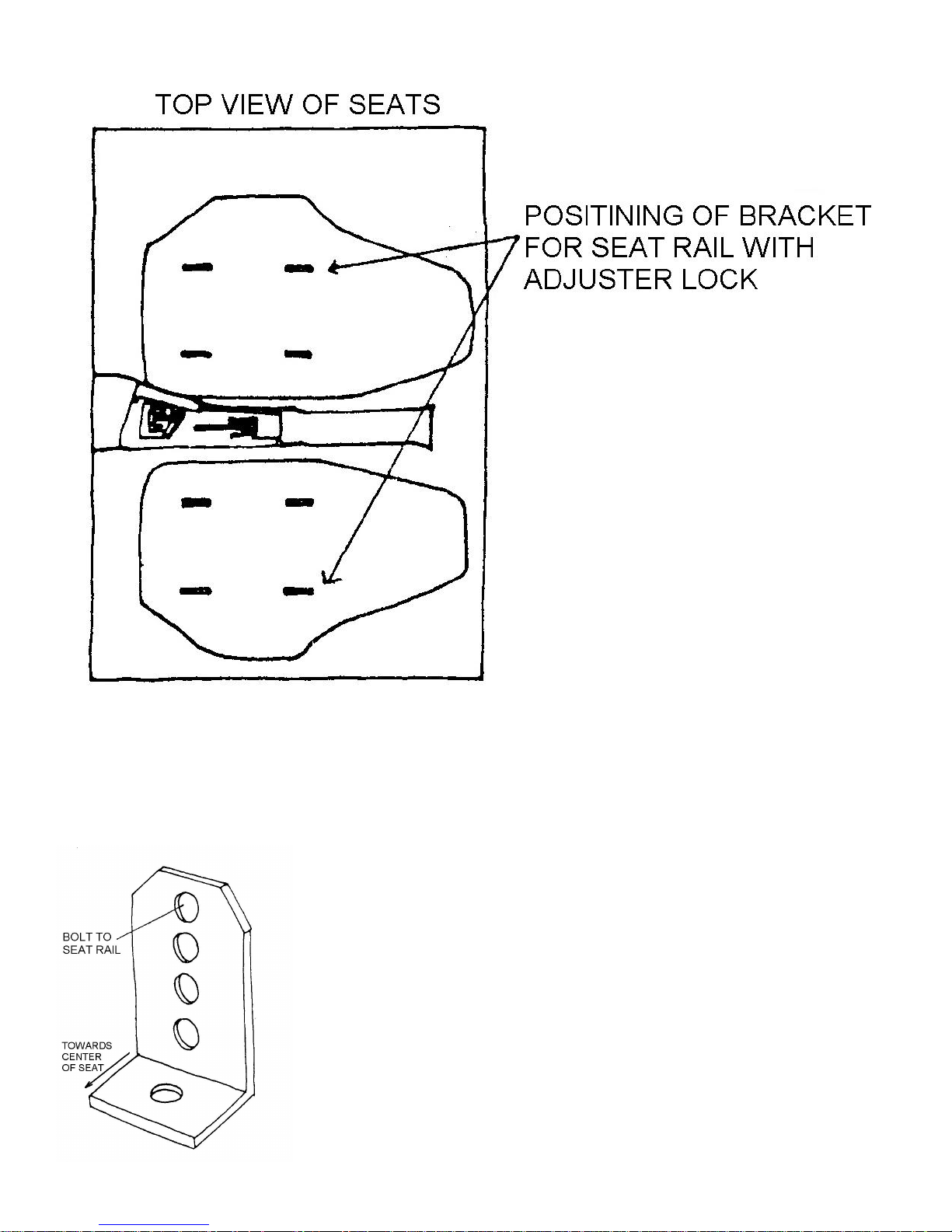
Figure 105 Location of Seat Brackets Under Seats
Figure 106 shows the seat brackets. The four holes in the vertical part are for adjustment of the seat height. Bolt
the bracket to each end of the seat rail through the top hole in the bracket. Use bolt kit #27. The ‘L’ of the bracket should
face the center of the seat. Apply contact cement to the rear of the seat back and seat back rug. Allow the cement to dry
and press the rug in place as in Figure 107. Install the seat cover in place as in Figure 108.
Figure 106 Seat Bracket
Page 86
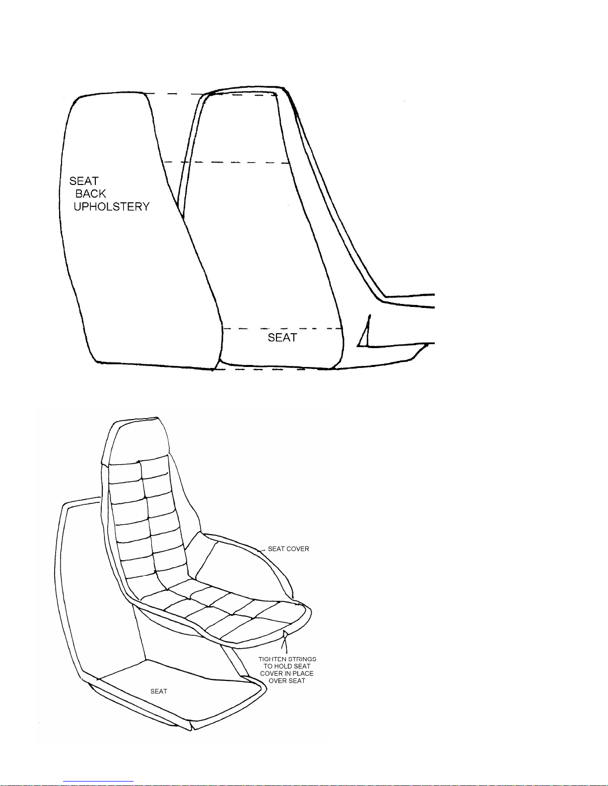
Figure 107 Seat Back Upholstery
Figure 108 Installing Seat Covers
Page 87
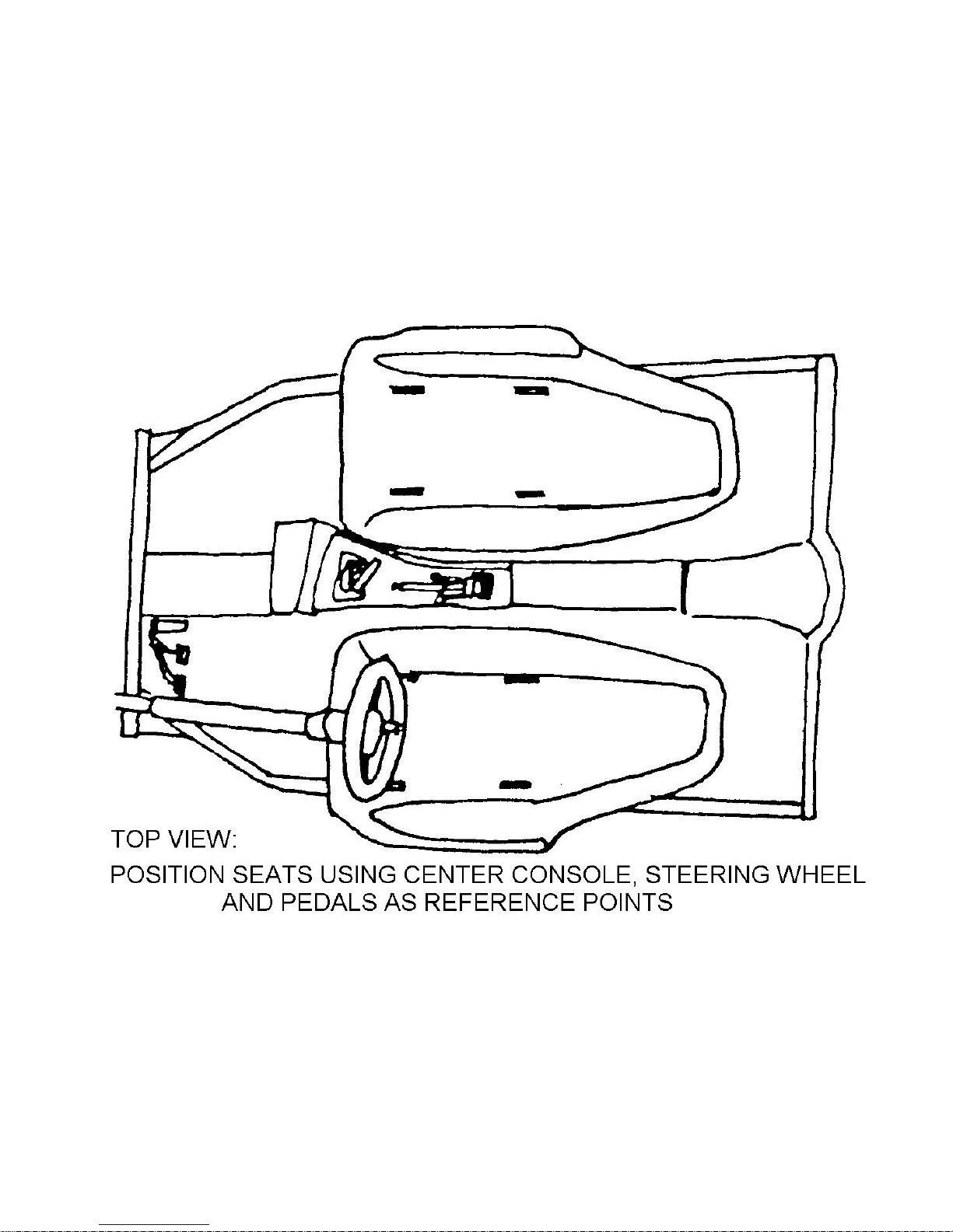
Set the lockable seat rail in the center position and place the seats in the car as shown in Figure 109. Look at the
seat bottom. It must be level from the side to side and should be slightly raised in the front. Adjust as necessary using the
vertical holes in the brackets.
Mark the location of the brackets on the carpet for reference, this can be done with a piece of masking tape and
find the seat location best suited to you by adjusting the seat as desired.
Once you find the proper seating position, mark the location of the brackets on the rug with chalk. Use the bracket
as a template and drill 5/16 inch mounting holes through the carpet and chassis. Bolt the seat brackets to the chassis floor
with bolt kit #28 as shown in Figure 110.
Figure 109 Positioning Seat in Body
Page 88
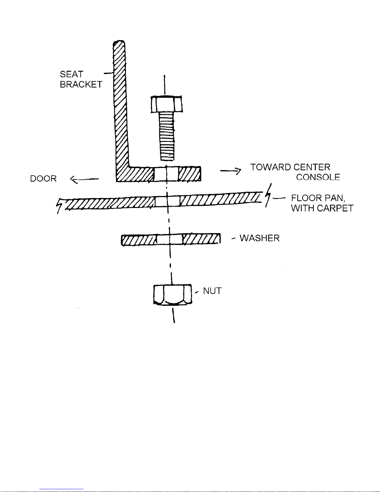
Figure 110 Detail: Seat Bracket to Chassis
Page 89
TAIL SECTION
Tools Required Drill
¼ inch Drill Bit
1/16 inch Drill Bit
3 inch Hole Saw
Jigsaw
Tape
Phillips Screwdriver
Socket Set
Carbide Router Bit
40 and 80 Grit Sandpaper
Assorted Files
Parts Required Ff #Z736 Taillights
Ff #Z737 Red Side Marker Lights
Ff #Z738 Four Light Brackets
Bolt Kit #29
Bolt Kit #30
Refer to Figures 111 through 118
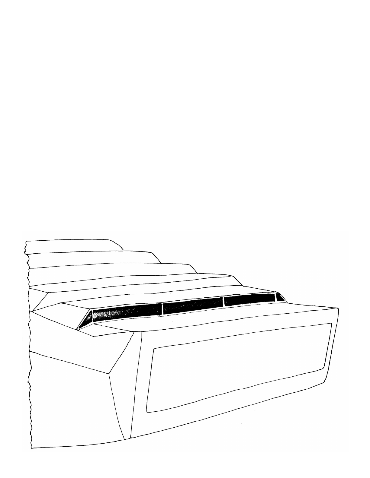
To cut the louver holes open, drill a ¼ inch hole about 1/6 inch away from the scribe line. Use a carbide router bit
to cut the holes open along the scribe lines. File and sand smooth and straighten the edges cut. Figure 111 shows louvers
being but open.
Measure and mark the rear panel for the taillight assemblies using dimensions given in Figure 112. Cut the
openings with a jigsaw.
Figure 111 Tail Louvers – Cut Recessed Lines Sand to Scribe
Page 90
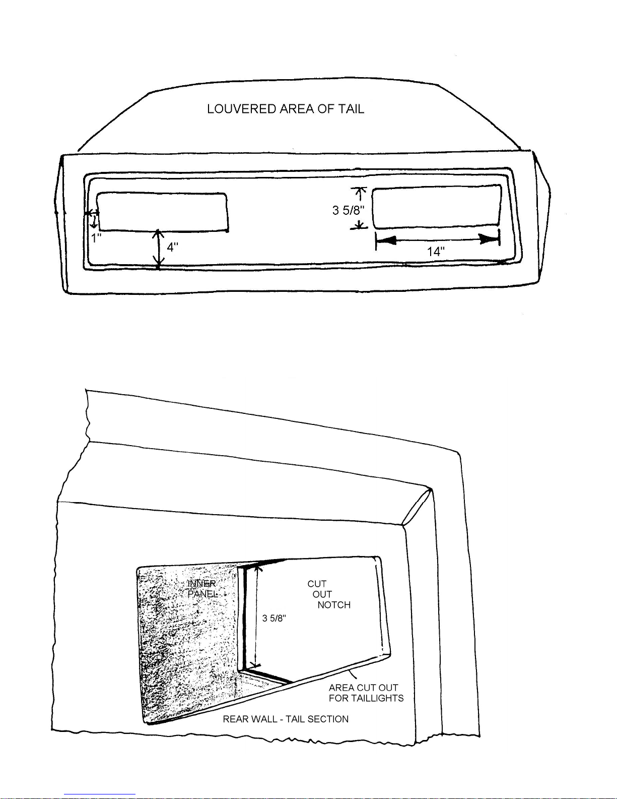
Figure 112 Locating Taillights
The rear panel will meet the inner panels at right angles on each side of the car. The inner panels must have a 3inch notch cut in them, as shown in Figure 113, to allow for the fittings of the light assembly.
Figure 113 Inner Panel Notch – Taillights
Page 91

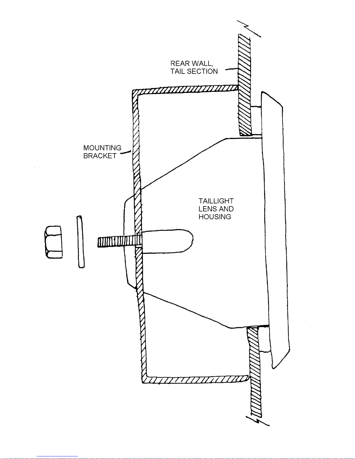
Place the taillight units in the holes and put the mounting brackets over the bolts in the light units. Secure the
taillights in place with bolt kit #29 and in Figure 114.
Figure 114 Installing Taillights
Page 92
Page 93
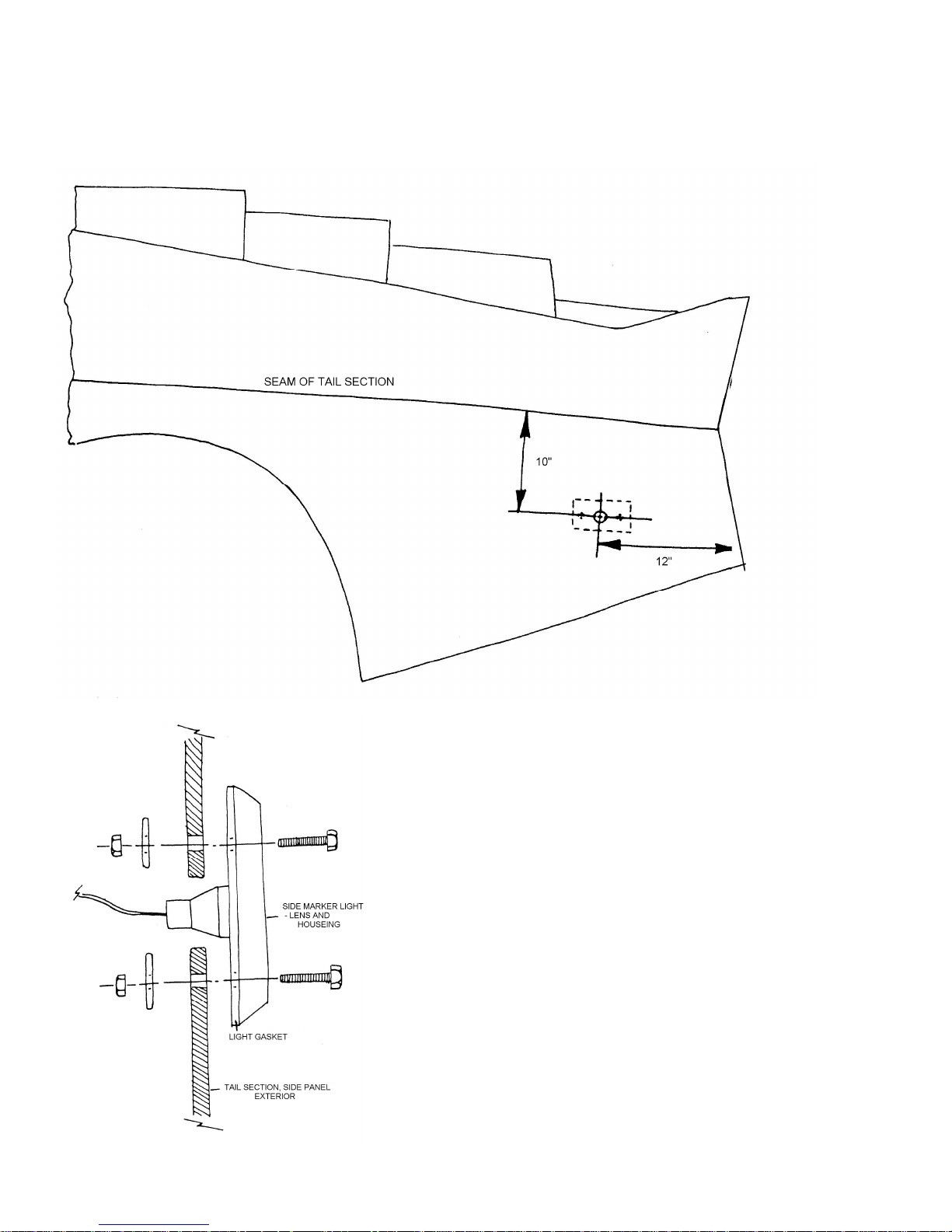
Measure and mark the center for the side marker lights using dimensions shown in Figure 115. Place the light
gasket over the center mark and scribe the outline for the lights and cut the hole open. Mark the location of the mounting
studs on the tail section and drill them with a 1/8-inch drill bit. Bolt the light in place as shown in Figure 116 using bolt kit
#30.
Figure 115 Locating Side Marker Lights
Figure 116 Installing Side Marker Lights
Page 94
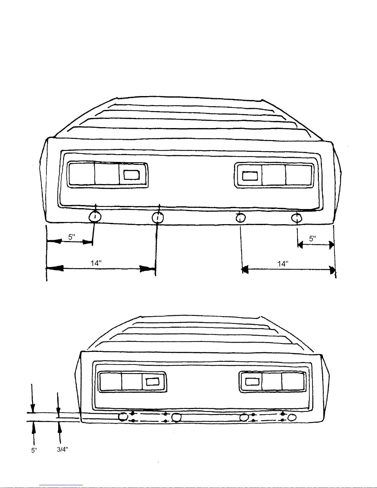
Mark the rear panel as shown in Figure 117 and cut 3-inch holes at these points. This will give access for bolting
the bumper in place and wiring.
Scribe two lines, ¾ inch and 5 inches from the bottom edge of the rear panel. Mark four points along each line
near the 3-inch access holes as shown in Figure 118. Drill the marked points with a ¼ inch drill bit. These holes will be for
the bolts that mount the rear bumper.
Figure 117 Cutting 3-Inch Access Holes
Figure 118 Locating Bumper Mounting Holes On Tail Section
Page 95
2. Installing the Rear Bumper
Tools Required Drill
¼ inch Drill Bit
Hole Saw
7/16 inch Wrench
Socket Set
120 Grit Sandpaper
Two 6-inch ‘C’ Clamps
Parts Required Bolt Kit #31 and #32
Ff #Z758 Two License Plate Lights
Two Steel Washers
Refer to Figures 119 to 122
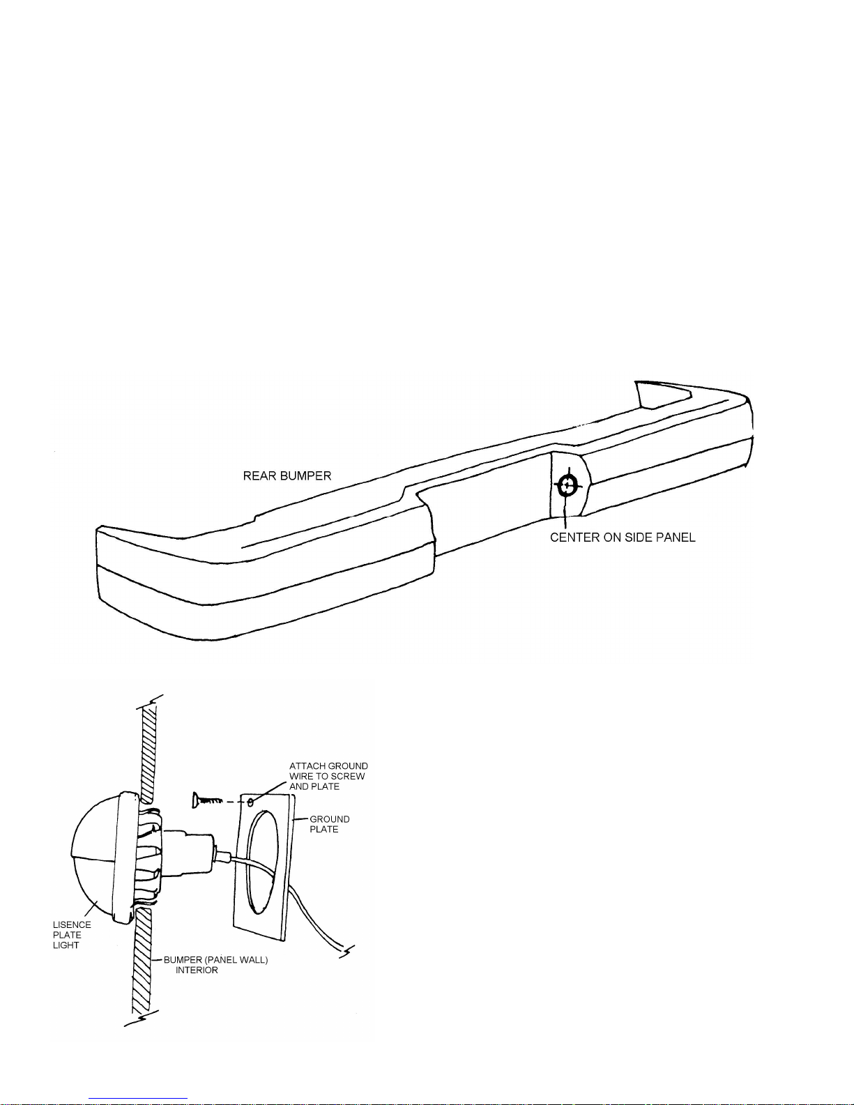
Sand the bumper flanges smooth with 120 grit sandpaper. Mark and drill the holes for the license plate lights as in
Figure 119. Install the lights as in Figure 120 using bolt kit #31
Figure 119 Locating License Plate Lights
Figure 120 Installing License Plate Lights
Page 96
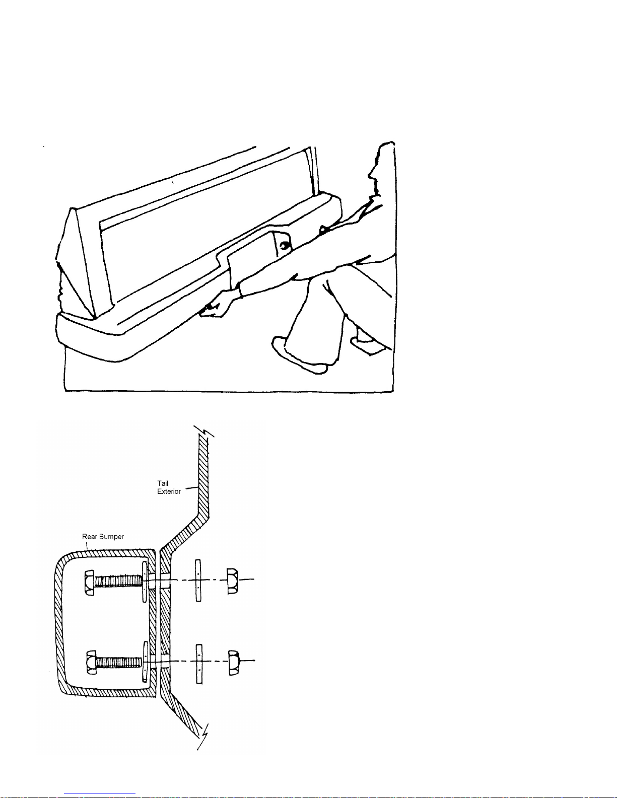
Position the bumper on the rear panel with the lower edge of the bumper even with the lower edge of the body.
Clamp the bumper to the body or have an assistant hold the bumper in place as shown in Figure 121
From inside the car, drill through the eight bumper mounting holes into the bumper flanges with ¼ inch drill bit.
Reaching through the 3-inch access holes, bolt the bumper in place as shown in Figure 122 using bolt kit #32.
Figure 121 Positioning Bumper on Tail
Figure 122 Attaching Bumper
Page 97
3. Installing the Tail Section
Tools Required Masking Tape
Drill
¼ inch Drill Bit
3/8 inch Drill Bit
9/16 inch Wrench
Socket Set
1-5/8 inch Hole Saw
Rattail File
80 Grit Sandpaper
Two ‘C’ Clamps
Parts Required Ff #M560G Wire Ties from Wiring Kit
Bolt Kit #33
Ff Z766 Two Tail Section Adjusters
Refer to Figures 123 through 128
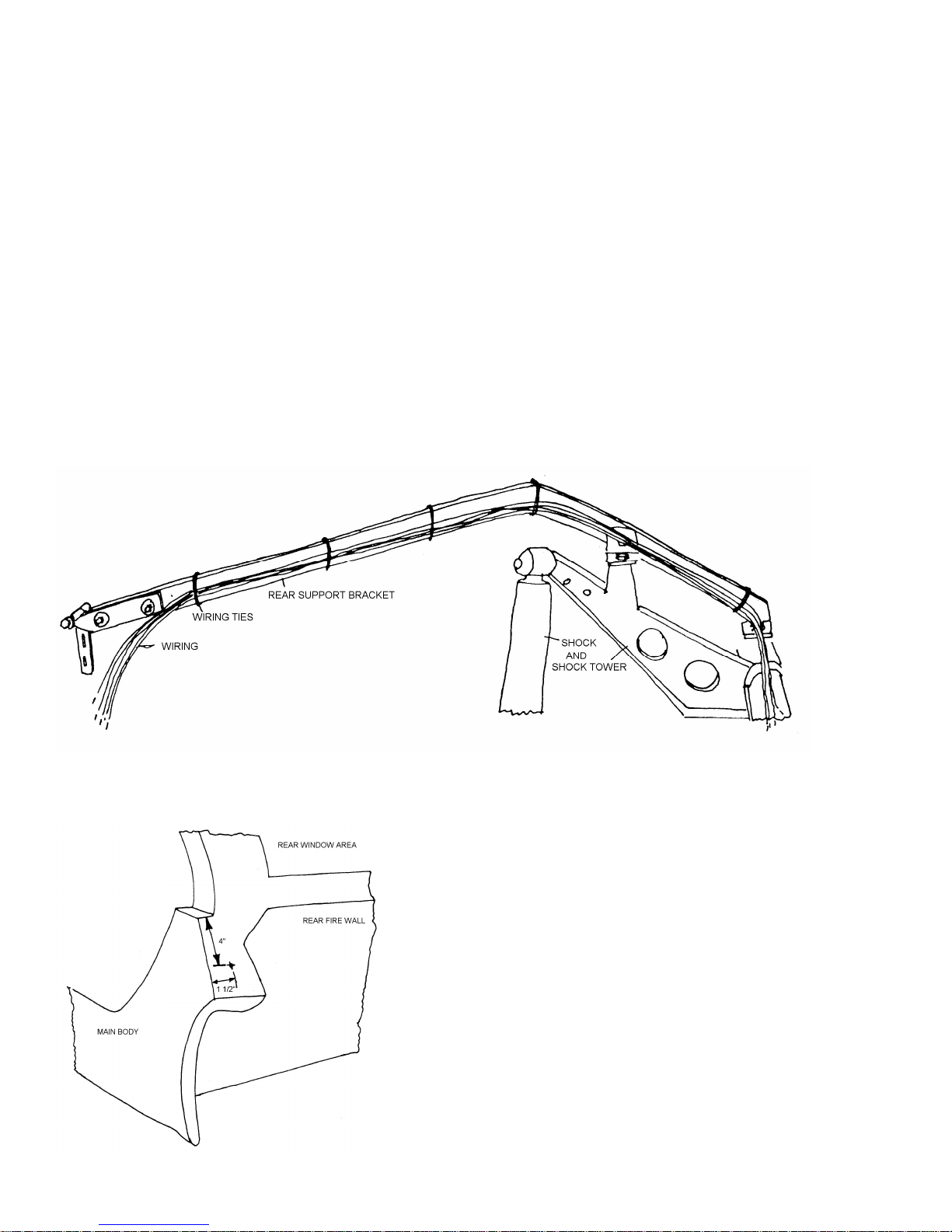
Run the wiring for the engine along the tail section supports and fasten to the supports using the wire ties in the
wiring kit as shown in Figure 123. Wire the engine according to the directions in the wiring kit.
Figure 123 Routing Wiring to Rear Section
On the rear of each side flange of the main body over the wheel well mark a point 4 inches from the top edge and
1-1/4 inches from the outer edge as in Figure 124. Drill these points using a ¼ inch drill bit.
Figure 124 Locating Holes for Anti-Sway Cushions
Page 98
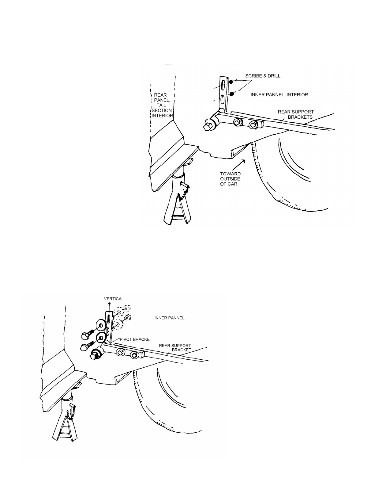
Place the tail section on the chassis. The ends of the rear support brackets should fit on the inside of the inner
panel as shown in Figure 125. The front of the tail section should meet with the doors at th top of the main body. The
wheel well flanges should aligh with those on the main body. Clamp the tail section to the main body at the wheel well
flanges. Place jack stands under the rear of the tail section for support.
Figure 125 Location Support Brackets on Inner Panel
Place the pivot brackets of the tail section supports in a vertical position. Mark the center of the slotted holes in
the pivot bracket on the inner panel. Drill these marks with a 3/8-inch drill bit. Bolt the brackets to the liner using bolts left
in bolt kit #1 as shown in Figure 126. Remove the clamps and jack stands and check the alignment of the tail section with
the main body. The tail can be moved forward or back by adjusting the horizontal pivot bracket on the rear supports. The
tail section be raised or lowered at the slotted holes in the pivot bracket attached to the inner panel. If additional
adjustments up and down is needed, this can be done at the ‘L’ bracket bolting the tail support to the chassis. Once the
proper alignment is achieved, tighten all nuts and bolts securely.
Figure 126 Pivot Brackets to Inner Panel
Page 99
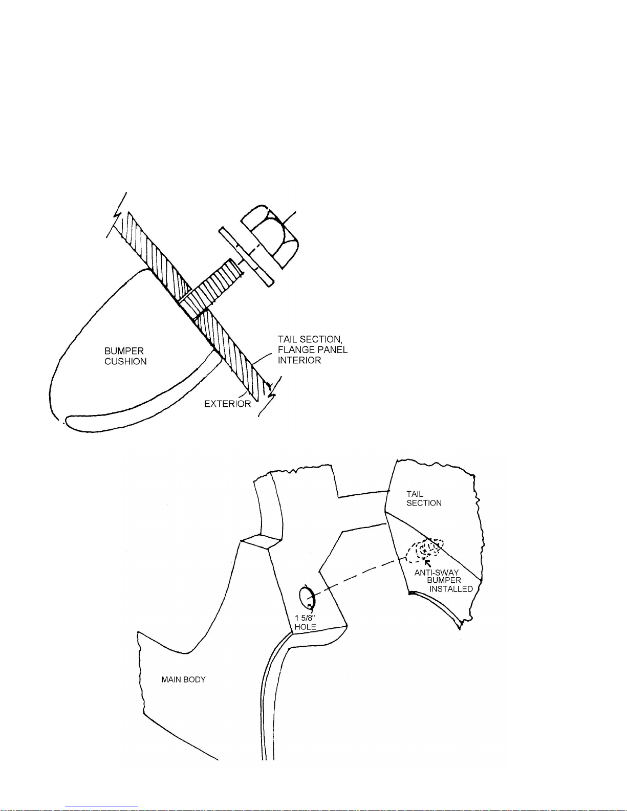
Clamp the body and tail section together at the wheel wells with ‘C’ clamps. Using the previously drilled hole in
the main body flange as a guide, reach up through the fender well and drill a ¼ inch hole in the matching tail section
flange. Remove the clamps.
Raise the tail section to the open position and enlarge the ¼ inch hole just drilled to ½ inch. Bolt the anti-sway
bumper in place with bolt kit #33 as shown in Figure 127.
Drill the matching ¼ inch in the main body flange to 1-5/8 inches with a hole saw. Close the tail section to check
alignment of the tail section adjusters with the 1-5/8 inch holes. Adjust the hole size by sanding if necessary. See Figure
128.
Figure 127 Installing Anti-Sway Bumper
Figure 128 Alignment – Anti-Sway Bumpers to Main Body
Page 100
5. Tail Section Holding Pins
Tools Required Masking Tape
Drill
1/8 inch Drill Bit
¼ inch Drill Bit
5/8 inch Drill Bit
Rattail File
Screwdriver
Crescent Wrench
Parts Required Ff #X113 Tail Section Hold Down Pins
Ff #Z766 Tail Section Adjusters
Bolt Kits #34 and #35
Refer to Figures 129 through 133
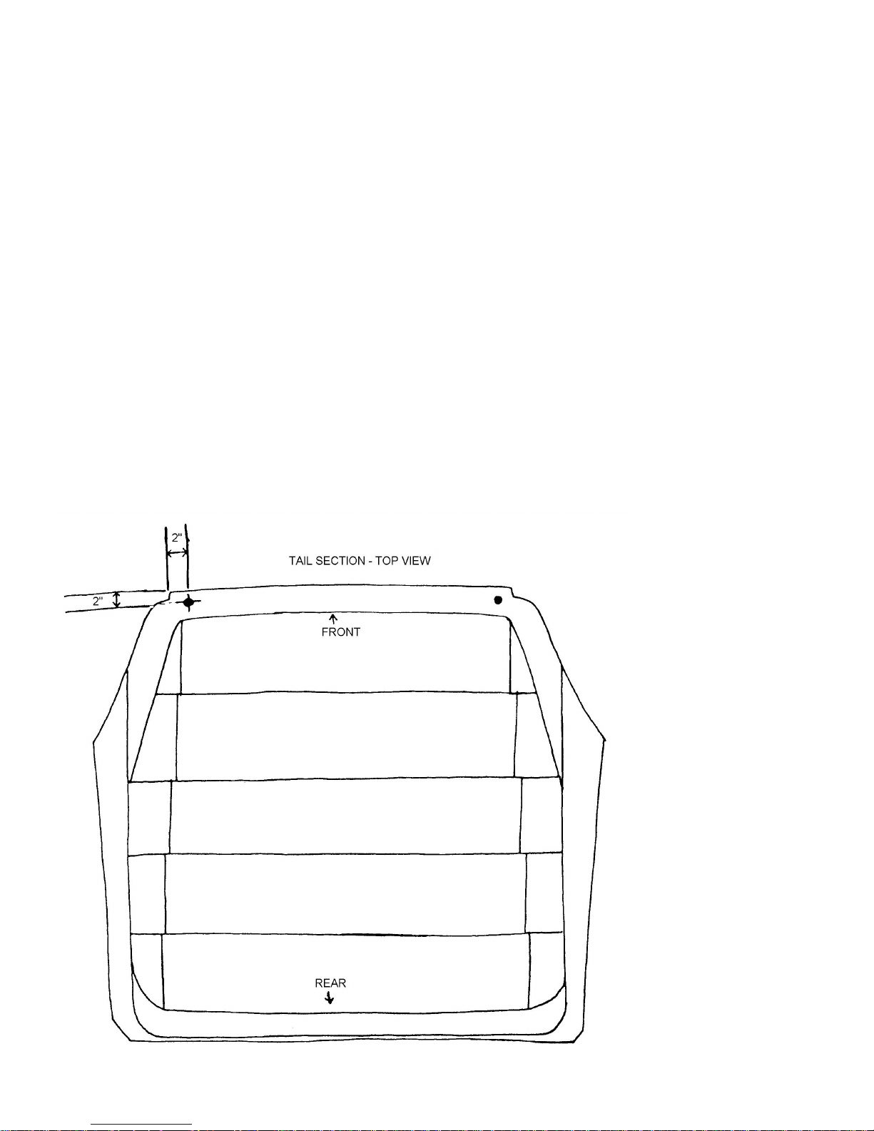
Mark the points for the hold-down pins as shown in Figure 129 and drill these marks with a ¼ inch drill bit. With
the tail section in the closed position, mark the main body section through the ¼ inch holes. Open the tail section and drill
the marks with a ¼ inch drill bit. Enlarge the hole to accept the hold-down pins by drilling the ¼ inch hole with a 5/8-inch
drill bit. Do the same with the ¼ inch holes just drilled in the tail section. Install the hold-down pins in the main body as
shown in Figure 130 using the large nuts and washers in bolt kit #34. Enlarge the holes in the tail section using a rattail file
so the pins clear the fiberglass when the tail is opened and closed.
When the pins clear the tail section close the tail and place the metal plate over the end of the hood pin. Mark the
holes in the plate to the tail section with the screws included in the hold-down pin kit.
Figure 129 Locating Holding Pins on the Tail
 Loading...