

Page 1
OPERATING
MANUAL
EN
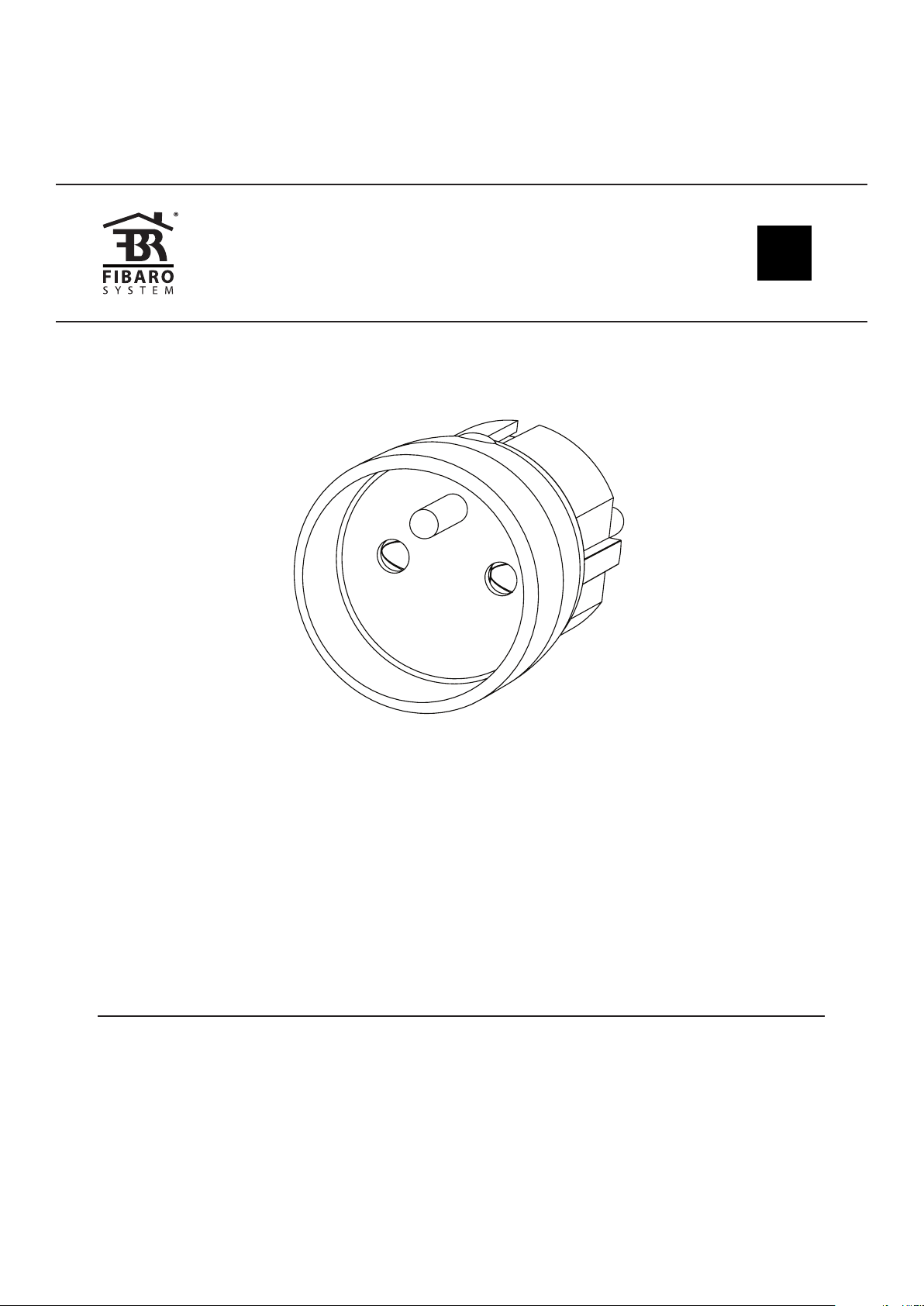
FIBARO WALL PLUG
FGWP-102
CONTENTS
#1: Description and features 3
#2: Basic activation 4
#3: Adding the device 5
#4: Removing the device 6
#5: Operating the device 7
#6: Power and energy consumption 9
v2.1
#7: Association 10
#8: Z-Wave range test 11
#9: Advanced parameters 12
#10: Specications 19
#11: Regulations 20
Page 2

2
Important safety information
Read this manual before attempting to install the device!
!
Failure to observe recommendations included in this manual
may be dangerous or cause a violation of the law. The manufacturer,
Fibar Group S.A. will not be held responsible for any loss or damage
resulting from not following the instructions of operating manual.
This product is intended for indoor use only in dry locations.
!
Do not use in damp or wet locations, near a bathtub, sink,
shower, swimming pool, or anywhere else where water or moisture
are present.
General information about
the FIBARO System
FIBARO is a wireless smart home automation system, based on the
Z-Wave protocol. All of available devices can be controlled through
a computer (PC or Mac), smartphone or tablet. Z-Wave devices are
not only receivers, but can also repeat the signal, increasing the
Z-Wave network’s range. It gives advantage over traditional wireless
systems that require direct link between transmitter and receiver, as
a result the construction of the building could aect network’s range
negatively.
Every Z-Wave network has its unique identication number (home
ID). Multiple independent networks can exist in the building without
interfering. Transmission security of FIBARO System is comparable to
wired systems.
Z-Wave technology is the leading solution in smart home automation.
There is a wide range of Z-Wave devices that are mutually
compatible, independently of manufacturer. It gives the system the
ability to evolve and expand over time. For more information visit:
www.baro.com.
Page 3
#1: Description and features
FIBARO Wall Plug is a universal, Z-Wave Plus compatible, remotely
controlled outlet adapter. This device may be applied wherever you
want to control electrical devices with up to 2500W load.
The Wall Plug is equipped with a power and energy metering
function. It uses a LED ring to visualize the current load with colour
changing illumination and operating mode. This is the smallest and
most attractive device of this type available in the world.
The Wall Plug may be operated using the B-button located on its
casing or via any Z-Wave compatible controller.
3
Main features of FIBARO Wall Plug:
• Compatible with any Z-Wave or Z-Wave+ Controller.
• Supports protected mode (Z-Wave network security mode) with
AES-128 encryption.
• Extremely easy installation - simply plug the device into the mains
socket.
• Works as a Z-Wave signal repeater.
• Active power and energy consumption metering.
• Current value of the load and operating mode are indicated by the
multi-colour LED ring.
FIBARO Wall Plug is a fully
compatible Z-Wave PLUS device.
NOTE
i
This device may be
used with all devices certied with
the Z-Wave Plus certicate and should be
compatible with such
devices produced by
other manufacturers.
NOTE
i
FIBARO Wall Plug is
a Security Enabled
Z-Wave Plus product
and a Security Enabled Z-Wave Controller must be used in order to fully utilize the
product.
DESCRIPTION AND FEATURES
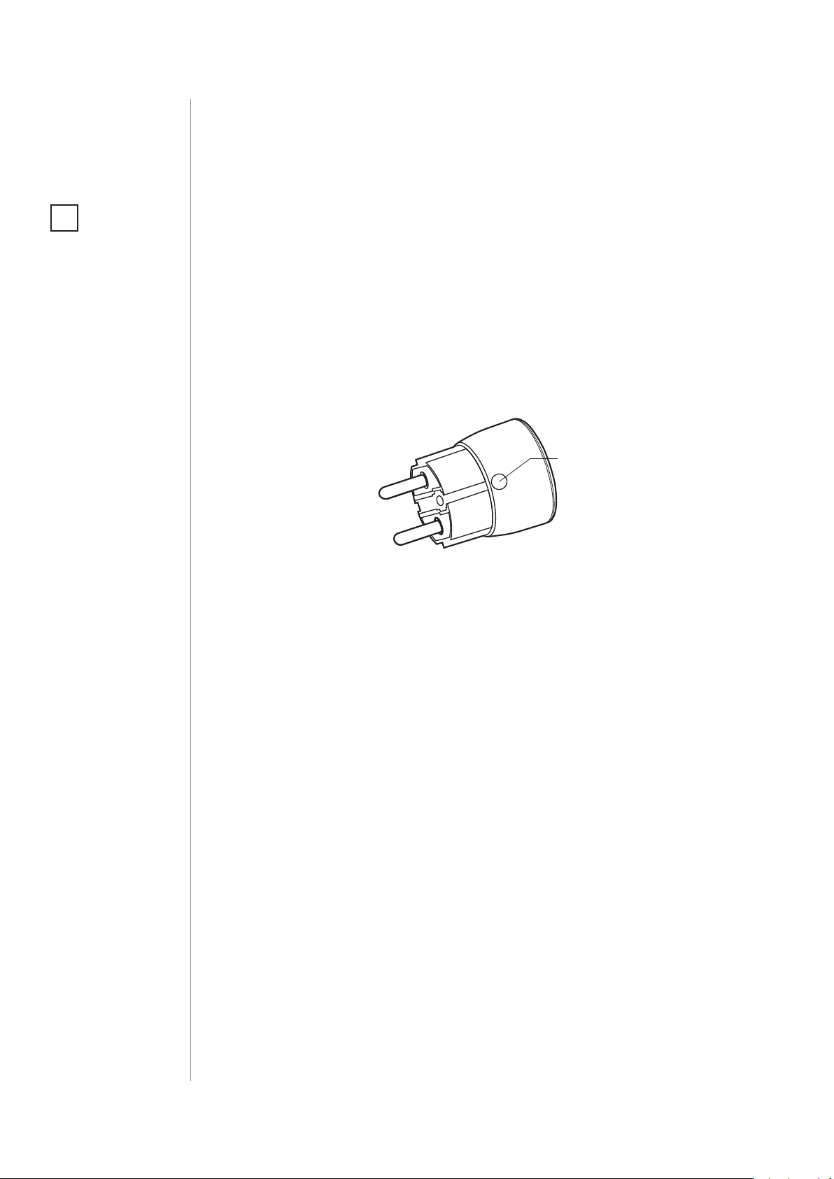
Page 4
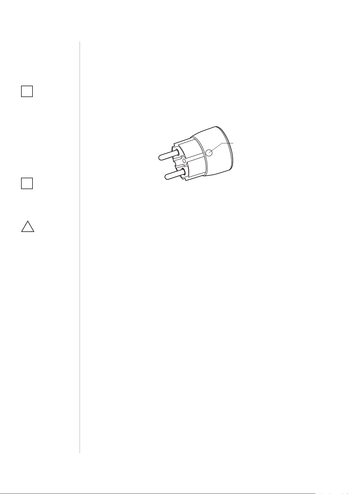
4
B-button
#2: Basic activation
NOTE
i
When powered, the
device will indicate
Z-Wave status with
colour of LED ring:
• Green - the device is
already added to the
Z-Wave network.
• Red - the device is
not added to any
Z-Wave network.
NOTE
i
Socket used for
the Wall Plug should
be easily accessible.
CAUTION
!
Do not put one
Wall Plug into another.
1. Plug the device into a socket nearby the main Z-Wave controller.
2. Set the main controller in (security/non-security) add mode (see
the controller’s manual).
3. Quickly, triple click the B-button located on the casing.
4. Wait for the device to be added to the system.
5. Successful adding will be conrmed by the controller.
6. Plug a device you want to control into the Wall Plug.
7. Test the device by turning it on and o using the B-Button.
BASIC ACTIVATION
Page 5
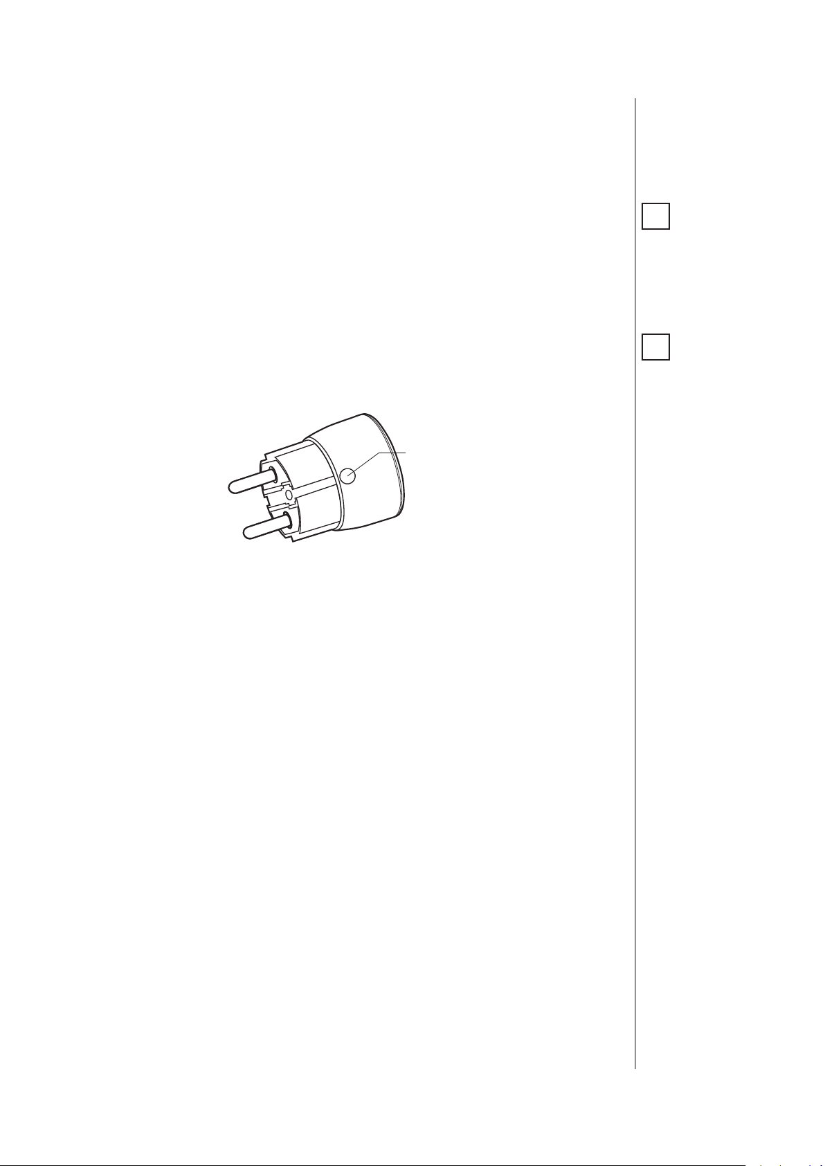
#3: Adding the device
B-button
5
Adding (Inclusion) - Z-Wave device learning mode, allowing to add
the device to existing Z-Wave network.
To add the device to the Z-Wave network:
1. Plug the device into a socket nearby the main Z-Wave controller.
2. The LED ring will glow red signalling not being added (reset or
remove the device otherwise).
3. Set the main controller in (security/non-security) add mode (see
the controller’s manual).
4. Quickly, triple click the B-button located on the casing.
5. Wait for the adding process to end.
6. Successful adding will be conrmed by the Z-Wave controller’s
message.
NOTE
i
Adding in security
mode must be performed up to 2 meters
from the controller.
NOTE
i
In case the device is
not added, please
reset the device and
repeat the adding
procedure.
ADDING THE DEVICE
Page 6
6
B-button
#4: Removing the device
NOTE
i
Removing the Wall Plug
from the Z-Wave network restores all the
default parameters of
the device.
Removing (Exclusion) - Z-Wave device learning mode, allowing to
remove the device from existing Z-Wave network.
To remove the device from the Z-Wave network:
1. Plug the device into a socket nearby the main Z-Wave controller.
2. The LED ring will glow green signalling being added (removing is
not necessary otherwise).
3. Set the main controller into remove mode (see the controller’s
manual).
4. Quickly, triple click the B-button located on the casing.
5. Wait for the removing process to end.
6. Successful removing will be conrmed by the Z-Wave controller’s
message.
REMOVING THE DEVICE
Page 7

#5: Operating the device
7
Controlling the Wall Plug using the B-button:
Wall Plug is equipped with a B-button, which allows to use the menu
and additionally perform the following actions:
1x click: turn controlled device ON/OFF, conrm selected menu option (if menu is active)
3x click: add/remove the device to/from a Z-Wave network
Holding: enter/navigate through menu
Visual indications:
The Wall Plug is equipped with a LED ring, signalling sensor’s operating modes and current active power consumption. In addition the
visual indicator may inform of the Z-Wave network range.
Visual indicator ring signalling modes:
1. By default, when the device is turned ON, the colour will vary depending on the current active power consumption.
2. Once inserted to mains socket the device signals Z-Wave network
inclusion status with blink (green - added, red - not added).
CAUTION
!
To avoid risk of electrical shock, do not operate the device with
wet or moist hands.
3. Menu position is signalled with assigned illumination colour.
4. Ongoing software update is signalled with cyan blinking.
5. Range of the Z-Wave network with colour depending on type of
communication or the lack of it (only in range tester mode).
Menu allows to perform Z-Wave network actions. In order to use the
menu:
1. Press and hold the B-button.
2. Wait for the device to indicate desired position with a colour:
• GREEN - erase energy consumption memory
• VIOLET - Z-Wave network’s range test
• YELLOW - device reset
3. Release the B-button.
4. Click the B-button to conrm selection.
NOTE
i
Menu is preceded by
two white ashes of
the LED ring 6 seconds
after the B-button is
pressed.
OPERATING THE DEVICE
Page 8

8
NOTE
i
Disabling the LED ring
indications will also
aect alarm signalization.
Disabling visual indicator:
Visual indication ring may be turned o for status signalling (turned
ON/OFF, power consumption). That means each status change will
be signalled by a short white blink of the ring. Disabling it will not
change operation of the device. To disable the LED ring:
1. Insert the Wall Plug in a socket.
2. Press and hold the B-button for about 3 seconds.
3. Release the B-button after LED ring starts pulsing white.
To restore visual indications perform above procedure again.
Controlling the Wall Plug with FIBARO Home Center controller:
The Wall Plug after successful adding is represented in the
Home Center interface with a single icon. It allows to turn on and o
the device and displays current active power and cumulative energy
consumption.
NOTE
i
Resetting the device is
not the recommended way of removing
the device from the
Z-Wave network. Use
reset procedure only
if the primary controller is missing or
inoperable. Certain
device removal can
be achieved by the
procedure of removing described in “Adding the device” on
page 5.
Resetting the device to factory defaults:
Reset procedure allows to restore the device back to its factory settings, which means all information about the Z-Wave controller and
user conguration will be deleted.
1. Make sure the device is powered.
2. Press and hold the B-button.
3. Wait for the LED ring to glow yellow (3rd menu position).
4. Release the B-button.
5. Click the B-button once to conrm selection.
6. After few seconds the device will restart with factory settings,
which is signalled with the red ring colour.
OPERATING THE DEVICE
Page 9

#6: Power and energy
consumption
The Wall Plug allows to monitor the active power and energy consumption. Data is sent to the main Z-Wave controller, e.g. Home
Center. Measuring is carried out by the most advanced micro-controller technology, assuring maximum accuracy and precision.
Electric active power - power that energy receiver is changing into a
work or a heat. The unit of active power is Watt [W].
Electric energy - energy consumed by a device through a time
period. Consumers of electricity in households are billed by suppliers on the basis of active power used in given unit of time. Most
commonly measured in kilowatt-hour [kWh]. One kilowatt-hour is
equal to one kilowatt of power consumed over period of one hour,
1kWh = 1000Wh.
9
Resetting consumption memory:
Wall Plug allows to erase stored consumption data (turning it o/on
or removing it from the socket will not erase consumption):
1. Make sure the device is powered.
2. Press and hold the B-button.
3. Release the B-button when the LED ring glows green (1st menu
position).
4. Press the B-button briey.
POWER AND ENERGY CONSUMPTION
Page 10

10
#7: Association
NOTE
i
Association ensures
direct transfer of
control commands
between devices, is
performed without
participation of the
main controller and
requires associated
device to be in the direct range.
NOTE
i
2nd association group
commands are sent
only in case of manual
operation through the
B-button.
3rd association group
commands are sent
automatically, depending on parameters 21, 22, 23 and 24.
Association (linking devices) - direct control of other devices within
the Z-Wave system network e.g. Dimmer, Relay Switch, Roller Shutter
or scene (may be controlled only through a Z-Wave controller).
The Wall Plug provides the association of three groups:
1st Association Group – “Lifeline” reports the device status and al-
lows for assigning single device only (main controller by default).
2nd Association Group – “On/O (Button)” devices in this group
will be switched on or o when relay status is changed using the
B-button (uses Basic command class).
3rd Association Group – “On/O (Power)” devices in this group will
be switched on or o depending on the current load (uses Basic command class).
The Wall Plug in 2nd and 3rd group allows to control
up to 10 regular or multichannel devices per an association group.
“LifeLine” group is reserved solely for the controller and hence only 1
node can be assigned.
It is not recommended to associate more than 10 devices in general,
as the response time to control commands depends on the number
of associated devices. In extreme cases, system response may be delayed.
ASSOCIATION
To add an association (using the Home Center controller):
1. Go to the device options by clicking the icon:
2. Select the „Advanced” tab.
3. Click the “Setting Association” button.
4. Specify to which group and what devices are to be associated.
5. Save the changes.
6. Wait for the conguration process to end.
Page 11

#8: Z-Wave range test
11
The Wall Plug has a built in Z-Wave network main controller’s range
tester.
Follow the below instructions to test the main controller’s range:
1. Press and hold the B-button.
2. Wait for the LED ring to glow violet (2nd menu position).
3. Release the B-button.
4. Click the B-button once to conrm selection.
5. Visual indicator will indicate the Z-Wave network’s range (range
signalling modes described below).
6. To exit Z-Wave range test, press the B-button briey.
Z-Wave range tester signalling modes:
Visual indicator pulsing green - the Wall Plug attempts to establish
a direct communication with the main controller. If a direct communication attempt fails, the device will try to establish a routed communication, through other modules, which will be signalled by visual
indicator pulsing yellow.
Visual indicator glowing green - the Wall Plug communicates with
the main controller directly.
CAUTION
!
To make Z-Wave range
test possible, the device must be added
to the Z-Wave controller. Testing may stress
the network, so it is
recommended to perform the test only in
special cases.
NOTE
i
Communication mode
of the Wall Plug may
switch between direct
and one using routing, especially if the
device is on the limit
of the direct range.
Visual indicator pulsing yellow - the Wall Plug tries to establish a
routed communication with the main controller through other modules (repeaters).
Visual indicator glowing yellow - the Wall Plug communicates with
the main controller through the other modules. After 2 seconds the
device will retry to establish a direct communication with the main
controller, which will be signalled with visual indicator pulsing green.
Visual indicator pulsing violet - the Wall Plug does communicate at
the maximum distance of the Z-Wave network. If connection proves
successful it will be conrmed with a yellow glow. It’s not recommended to use the device at the range limit.
Visual indicator glowing red - the Wall Plug is not able to connect
to the main controller directly or through another Z-Wave network
device (repeater).
ZWAVE RANGE TEST
Page 12

12
#9: Advanced parameters
The Wall Plug allows to customize its operation to user’s needs. The
settings are available in the FIBARO interface as simple options that
may be chosen by selecting the appropriate box.
In order to congure the Wall Plug (using the FIBARO Home Center
controller):
1. Go to the device options by clicking the icon:
2. Select the „Advanced” tab.
3. Modify values of chosen parameters.
4. Save the changes.
GENERAL SETTINGS
1. “Always On” mode
In this mode Wall Plug will turn on connected device permanently and
will stop reacting to attempts of turning it o (through Z-Wave network
or pushing the B-button).
“Always On” function turns the Wall Plug into a power and energy meter. Connected device will not be turned o upon receiving an alarm
frame from another Z-Wave device (parameter 31 will be ignored).
In “Always on” mode, connected device may be turned o after exceeding the power dened in parameter 3 or in case of detecting
current greater than 110% of rated current. In such cases, connected
device can be turned on again by pushing the B-button or sending a
control frame. By default, overload protection is inactive.
Available settings: 0 - function inactive
1 - function activated
Default setting: 0 Parameter size: 1 [byte]
2. Remember device status before the power failure
This parameter determines how the Wall Plug will react in the event
of power supply failure (e.g. power outage or taking out from the
electrical outlet).
ADVANCED PARAMETERS
After the power supply is back on, the Wall Plug can be restored to
previous state or remain switched o.
This parameter is ignored in „Always On” mode - the device automatically turns ON after plugging it into the socket.
Available settings: 0 - device remains switched o
1 - device restores the state from before the
power failure
Default setting: 1 Parameter size: 1 [byte]
Page 13

3.
Overload safety switch
This function allows to turn o the controlled device in case of exceeding the dened power. Controlled device will be turned o even
if “Always On” function is active (parameter 1).
Controlled device can be turned back on via B-button or sending a
control frame. By default this function is inactive.
Available settings: 0 - function inactive
10-30000 (1.0-3000.0W, step 0.1W) - power
threshold
Default setting: 0 Parameter size: 2 [bytes]
POWER AND ENERGY MEASUREMENT
The default values of the parameters suit most types of devices. They
were selected to show in real time the instantaneous power values,
while not overloading the Z-Wave network in the process. In specic
cases it may be necessary to modify default settings in order to optimize Z-Wave network’s use. In extreme cases it is recommended to
turn o reporting completely and congure power polling or periodic reports in the Z-Wave controller.
The Wall Plug reports the power load with specied frequency. Below
conguration parameters allow to specify how and how frequently
power load will be reported.
10. High priority power report
This parameter determines the minimum percentage change in active power that will result in sending power report to the main controller with the highest priority in the Z-Wave network.
13
CAUTION
!
The device has a protection that will turn
the load o in the case
of detecting current
greater than 110% of
rated current (>12A).
It is a safety function and it cannot be
turned o. After its
activation the load
can be turned on back
again by pressing the
B-button or sending
a control frame. This
function is independent of overload safety
switch set in the parameter no. 3.
NOTE
i
Overload safety
functionality is not an
overload safety protection nor a short circuit protection. Circuit
needs additional short
circuit and overload
protection!
switch
By default, the Wall Plug immediately sends the power report if the
power load changes by 80%.
Available settings: 1-99 - power change in percent
100 - reports are disabled
Default setting: 80 (80%) Parameter size: 1 [byte]
11. Standard power report
This parameter determines the minimum percentage change in active
power that will result in sending power report to the main controller
Compared to parameter 10, the maximum number of reports sent is
reduced (parameter 12) to 5 in a specied time interval. In addition,
the reports are not sent in mode, which may result in overloading the
Z-Wave network.
By default changes in power load may be reported up to 5 times per
30 seconds, when power load changes by 15%.
Available settings: 1-99 - power change in percent
100 - reports are disabled
Default setting: 15 (15%) Parameter size: 1 [byte]
NOTE
i
In extreme cases, reports may be sent
every second if rapid
and signicant power
load changes occur.
Frequent reporting
may overload the
Z-Wave network so
these parameter’s settings should reect
signicant changes in
power load only.
ADVANCED PARAMETERS
Page 14

14
NOTE
i
By default the Wall
Plug sends up to 5 reports each 30 seconds,
provided the power
load changes by 15%.
12. Power reporting interval
This parameter denes the time interval of sending at most 5 standard power reports when the power changes by the value set in parameter 11. The higher the value of parameter 12, the fewer reports
the device will send.
Available settings: 5-600 (in seconds)
Default setting: 30 (30s) Parameter size: 2 [bytes]
13. Energy reporting threshold
This parameter species the minimum change in energy consumption (in relation to the previously reported), that will result in sending
a new report.
Available settings: 0 - energy reports inactive
1-500 (0.01-5kWh, step 0.01kWh) - threshold
Default setting:
10 (0.1kWh)
Parameter size: 2 [bytes]
14. Power and energy periodic reports
This parameter denes time period between independent reports
sent when changes in power load have not been recorded or if changes are insignicant. By default reports are sent every hour.
Available settings: 0 - periodic reports inactive
5-32400 (in seconds)
Default setting: 3600 (1h) Parameter size: 2 [bytes]
15. Measuring energy consumed by the Wall Plug itself
This parameter determines whether power metering should include
the amount of power consumed by the Wall Plug itself. Results are
being added to the value of power consumed by controlled device.
Available settings: 0 - function inactive
1 - function activated
Default setting: 0 Parameter size: 1 [byte]
„ON/OFF” ASSOCIATION GROUPS
20. Control of „On/O (Button)” association group (2) devices
Controlling devices with the B-Button. This parameter is inactive in
“Always On” mode (parameter 1).
Control as the Wall Plug:
• switching the Wall Plug on – switch the devices on (parameter 24)
• switching the Wall Plug o – switch the devices o (parameter 24)
ADVANCED PARAMETERS
Control opposite to the Wall Plug:
• switching the Wall Plug on – switch the devices o
• switching the Wall Plug o – switch the devices on
Page 15

Available settings: 0 - control as the Wall Plug
1 - control opposite to the Wall Plug
Default setting: 0 Parameter size: 1 [byte]
21. DOWN value - „On/O (Power)” association group (3)
Lower power threshold, used in parameter 23. DOWN value cannot
be higher than a value specied in parameter 22.
Available settings: 0-24900 (0.0-2490.0W, step 0.1W)
Default setting: 300 (30W) Parameter size: 2 [bytes]
22. UP value - „On/O (Power)” association group (3)
Upper power threshold, used in parameter 23. UP value cannot be
lower than a value specied in parameter 21.
Available settings: 100-25000 (10.0-2500.0W, step 0.1W)
Default setting: 500 (50W) Parameter size: 2 [bytes]
15
23. The response after exceeding dened power values
This parameter denes the way that 3rd association group devices are
controlled. Depends on the actual measured power (as parameters 21
and 22 settings).
Available settings:
1 - turn the associated devices ON, once the
power drops below DOWN value (parameter 21)
2 - turn the associated devices OFF, once the
power drops below DOWN value (parameter 21)
3 - turn the associated devices ON, once the
power rises above UP value (parameter 22)
4 - turn the associated devices OFF, once the
power rises above UP value (parameter 22)
5 - combination of 1 and 4.
Turn the associated devices ON, once the power drops below DOWN value (parameter 21).
Turn the associated devices OFF, once the power rises above UP value (parameter 22).
6 - combination of 2 and 3.
Turn the associated devices OFF, once the power drops below DOWN value (parameter 21).
Turn the associated devices ON, once the power rises above UP value (parameter 22).
Default setting: 6 Parameter size: 1 [byte]
ADVANCED PARAMETERS
Page 16

16
NOTE
i
Setting parameter 24
to appropriate value
will result in:
0 - turning o associated devices
1-99 - forcing level of
associated devices
255 - setting associated devices to the last
remembered state or
turning them on
24. SWITCH ON value - „On/O” association groups
The value of BASIC SET command frame sent to the devices associated in „On/O” association groups (2, 3).
„On/O (Button)” association group - in accordance with parameter 20.
„On/O (Power)” association group - in accordance with parameter 23.
Available settings: 0-99 or 255
Default setting: 255 Parameter size: 2 [bytes]
ALARMS
30. Active alarms
Dene Z-Wave network alarms to which the Wall Plug will respond.
Available settings: 1 - general alarm
2 - smoke alarm
4 - CO alarm
8 - CO2 alarm
16 - high temperature alarm
NOTE
i
If “Always On” function
is active (parameter 1),
settings of parameter
31 are ignored.
NOTE
i
The alarm may be cancelled by pressing and
holding the B-button.
32 - ood alarm
Default setting: 63 (all) Parameter size: 1 [byte]
31. Response to alarm frames
This parameter denes how the Wall Plug will respond to alarms (device’s status change).
In case of values 1 or 2 the Wall Plug is operating normally and LED
ring signals an alarm through time dened in parameter 32 or until
the alarm is cancelled.
In case of values 5 to 50 the Wall Plug does not report status change,
power changes, ignores BASIC SET command frames. After time dened in parameter 32 or after the alarm cancellation, connected device is set to the previous state.
Available settings: 0 - no reaction,
1 - turn connected device on
2 - turn connected device o
5-50 (0.5-5.0s, step 0.1s) - cyclically change de-
vice state with set period
Default setting: 0 Parameter size: 1 [byte]
ADVANCED PARAMETERS
32. Alarm state duration
This parameter species the duration of alarm state. If a device sending an alarm frame through the Z-Wave network sets alarm duration as
well, this settings are ignored.
Available settings: 1-32400 (in seconds)
Default setting: 600 (10min) Parameter size: 2 [bytes]
Page 17

COLOUR SETTINGS
40. Power load for violet colour
This parameter determines maximum active power value, which when
exceeded, causes the LED ring ash violet. Function is active only when
parameter 41 is set to 1 or 2.
Available settings: 1000-30000 (100.0-3000.0W, step 0.1W)
Default setting:
41. LED ring colour when controlled device is on
When set to 1 or 2, LED ring colour will change depending on active
power and parameter 40. Other colours are set permanently and do
not depend on power consumption.
Available settings: 0 - illumination turned o completely
25000 (2500W)
1 - colour changes continuously depending on
active power
2 - colour changes in steps depending on active power
Parameter size: 2 [bytes]
17
3 - white, 4 - red, 5 - green, 6 - blue, 7 - yellow
8 - cyan, 9 - magenta
Default setting: 1 Parameter size: 1 [byte]
42. LED ring colour when controlled device is o
This parameter denes the illumination colour after turning o.
Available settings: 0 - illumination turned o completely
1 - LED ring is illuminated with a colour corresponding to the last measured power, before
the controlled device was turned o
3 - white, 4 - red, 5 - green, 6 - blue, 7 - yellow
8 - cyan, 9 - magenta
Default setting: 0 Parameter size: 1 [byte]
43. LED ring colour at the Z-Wave network alarm detection
This parameter denes the illumination colour in case of Z-Wave alarm.
Available settings: 0 - illumination turned o completely
1 - no change in colour. LED ring colour is determined by settings of parameters 41 or 42
2 - LED ring ashes red/blue/white
3 - white, 4 - red, 5 - green, 6 - blue, 7 - yellow
8 - cyan, 9 - magenta
Default setting: 2 Parameter size: 1 [byte]
ADVANCED PARAMETERS
Page 18

18
OTHERS
50. Associations in Z-Wave network security mode
This parameter denes how commands are sent in specied association groups: as secure or non-secure. Parameter is active only in
Z-Wave network security mode. This parameter does not apply to 1st
„Lifeline” group.
Available settings: 0 - none of the groups sent as secure
1 - 2nd group sent as secure
2 - 3rd group sent as secure
3 - 2nd and 3rd group sent as secure
Default setting: 3 Parameter size: 1 [byte]
ADVANCED PARAMETERS
Page 19

#10: Specications
19
Power supply:
Rated load current
(for resistive load):
Power consumption:
Power output (for resistive
load):
To be used with E or
F type (Schuko) sockets:
Active element:
EU standards compliance:
Pollution Degree:
Radio protocol:
Radio frequency:
Range:
Operating temperature:
Dimensions (Diameter x
Height):
230V AC, 50/60 Hz
11A - continuous load
up to 1.6W
2.5kW at continuous load
- CEE 7/16 - max load 2.5A
- CEE 7/17 - max load 11A
- Dual type plugs E/F
Micro-gap relay switch
RoHS 2011/65/EU
RED 2014/53/EU
2 (home and oce use, indoor only)
Z-Wave (500 series chip)
868.4 or 869.8 MHz EU;
908.4, 908.42 or 916.0 MHz US;
921.4 or 919.8 MHz ANZ;
869.0 MHz RU;
up to 50m outdoors
up to 40m indoors
(depending on terrain and building
structure)
0 - 40°C
43 x 65 mm
NOTE
i
In case of loads other
than resistive please
observe cosφ and, if
necessary, use load
lower than rated. It is
recommended not to
exceed 3A for 250 V
AC, cosφ=0.4.
NOTE
i
Radio frequency of
individual device
must be same as your
Z-Wave controller.
Check information
on the box or consult
your dealer if you are
not sure.
Safety classication rating: home and oce use only
Type 1 action according to features of automatic action as per clause
6.4.1 of EN 60730-1:2012 standard.
Software class A device, according to EN 60730-1:2012 standard.
SPECIFICATIONS
Page 20

20
#11: Regulations
Legal Notices
All information, including, but not limited to, information regarding the
features, functionality, and/or other product specication are subject
to change without notice. Fibaro reserves all rights to revise or update its products, software, or documentation without any obligation to
notify any individual or entity.
FIBARO and Fibar Group logo are trademarks of Fibar Group S.A. All
other brands and product names referred to herein are trademarks of
their respective holders.
Warning
This product is not a toy. Keep away from children and animals!
Declaration of conformity
Hereby, Fibar Group S.A. declares that the device is in compliance with
the essential requirements and other relevant provisions of Directive
2014/53/EU. The full text of the EU declaration of conformity is available
at the following internet address: www.manuals.baro.com
WEEE Directive Compliance
Device labelled with this symbol should not be disposed with other
household wastes. It shall be handed over to the applicable collection
point for the recycling of waste electrical and electronic equipment.
REGULATIONS
 Loading...