

Page 1
OPERATING
MANUAL
EN
FIBARO MOTION SENSOR
FGMS-001
CONTENTS
#1: Description and features 3
#2: Basic activation 4
#3: Adding/removing the device 5
#4: Physical installation 6
#5: Operating the device 7
v2.1
#6: Association 9
#7: Z-Wave range test 10
#8: Advanced parameters 11
#9: Specications 18
#10: Regulations 19
Page 2

2
Important safety information
Read this manual before attempting to install the device!
Failure to observe recommendations included in this manual may
be dangerous or cause a violation of the law. The manufacturer,
Fibar Group S.A. will not be held responsible for any loss or damage
resulting from not following the instructions of operating manual.
The alarm functionality of devices is an additional feature increasing
the comfort level of your home automation system. If you want to
use professional security service, please contact them to determine
what systems can provide a protection of your estate.
Compliance with safety standards:
The device is designed to be used in Z-wave home automation systems (e.g. FIBARO) and is complaint with IEC/UL/CSA 60950-1. In case
of the integration with another system, e.g. alarm system, it is required to verify the compliance with additional standards.
General information about
the FIBARO System
FIBARO is a wireless smart home automation system, based on the
Z-Wave protocol. All of available devices can be controlled through
a computer (PC or Mac), smartphone or tablet. Z-Wave devices are
not only receivers, but can also repeat the signal, increasing the
Z-Wave network’s range. It gives advantage over traditional wireless
systems that require direct link between transmitter and receiver, as
a result the construction of the building could aect network’s range
negatively.
Every Z-Wave network has its unique identication number (home
ID). Multiple independent networks can exist in the building without
interfering. Transmission security of FIBARO System is comparable to
wired systems.
Z-Wave technology is the leading solution in smart home automation.
There is a wide range of Z-Wave devices that are mutually
compatible, independently of manufacturer. It gives the system the
ability to evolve and expand over time. For more information visit
www.baro.com.
Page 3

#1: Description and features
FIBARO Motion Sensor is a universal Z-Wave multi-sensor. Along
with detecting motion the device measures the temperature and
light intensity. The sensor has a built-in accelerometer to detect any
tampering of the device. FIBARO Motion Sensor is battery powered
device and designed to be installed quickly and easily on any surface.
The LED indicator signals motion, temperature level, operating
mode and can be used to see if device is within the Z-Wave network.
The motion sensor can be used for lighting scenes and presence
monitoring systems.
3
Main features of FIBARO Motion Sensor:
• compatible with any Z-Wave or Z-Wave+ Controller
• supports protected mode (Z-Wave network security mode) with AES128 encryption
• detects motion using a passive IR sensor
• measures ambient temperature
• measures light intensity
• detects vibrations
• extremely easy installation
• may be installed anywhere - wall or any surface
• battery powered
• theft and tampering protection - once vibrations are detected, the
notication is sent to the main controller
• detected movement, temperature and vibrations are signalled by
the built-in LED diode
NOTE
i
This device may be
used with all devices
certied with Z-Wave
Plus certicate and
should be compatible
with such devices produced by other manufacturers.
NOTE
i
FIBARO Motion Sensor
is a Security Enabled
Z-Wave Plus product
and a Security Enabled Z-Wave Controller must be used in order to fully utilize the
product.
FIBARO Motion Sensor is a fully
compatible Z-Wave PLUS device.
DESCRIPTION AND FEATURES
Page 4
4
#2: Basic activation
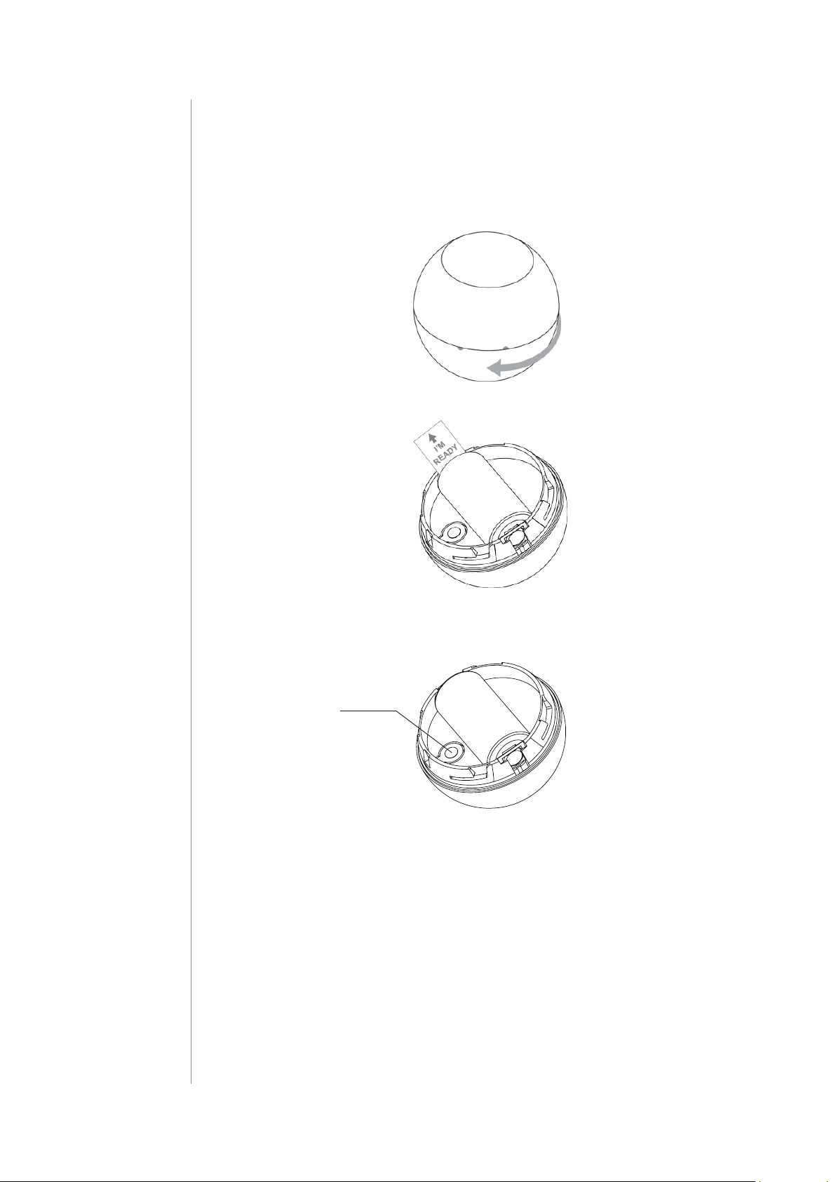
1. Turn the cover counter-clockwise and open it.
2. Remove the battery blocker.
3. Add the device (see “Adding/removing the device” on page 5).
4. Wake up the sensor by triple clicking the B-button.
B-button
5. Close the cover and turn it clockwise.
6. Install the device (see “Physical installation” on page 6).
BASIC ACTIVATION
Page 5
#3: Adding/removing the device
5
Adding (Inclusion) - Z-Wave device learning mode, allowing to add
the device to existing Z-Wave network.
To add the device to the Z-Wave network:
1. Open the cover.
2. Place the Motion Sensor within the direct range of your Z-Wave
controller.
3. Set the main controller in (security/non-security) add mode (see
the controller’s manual).
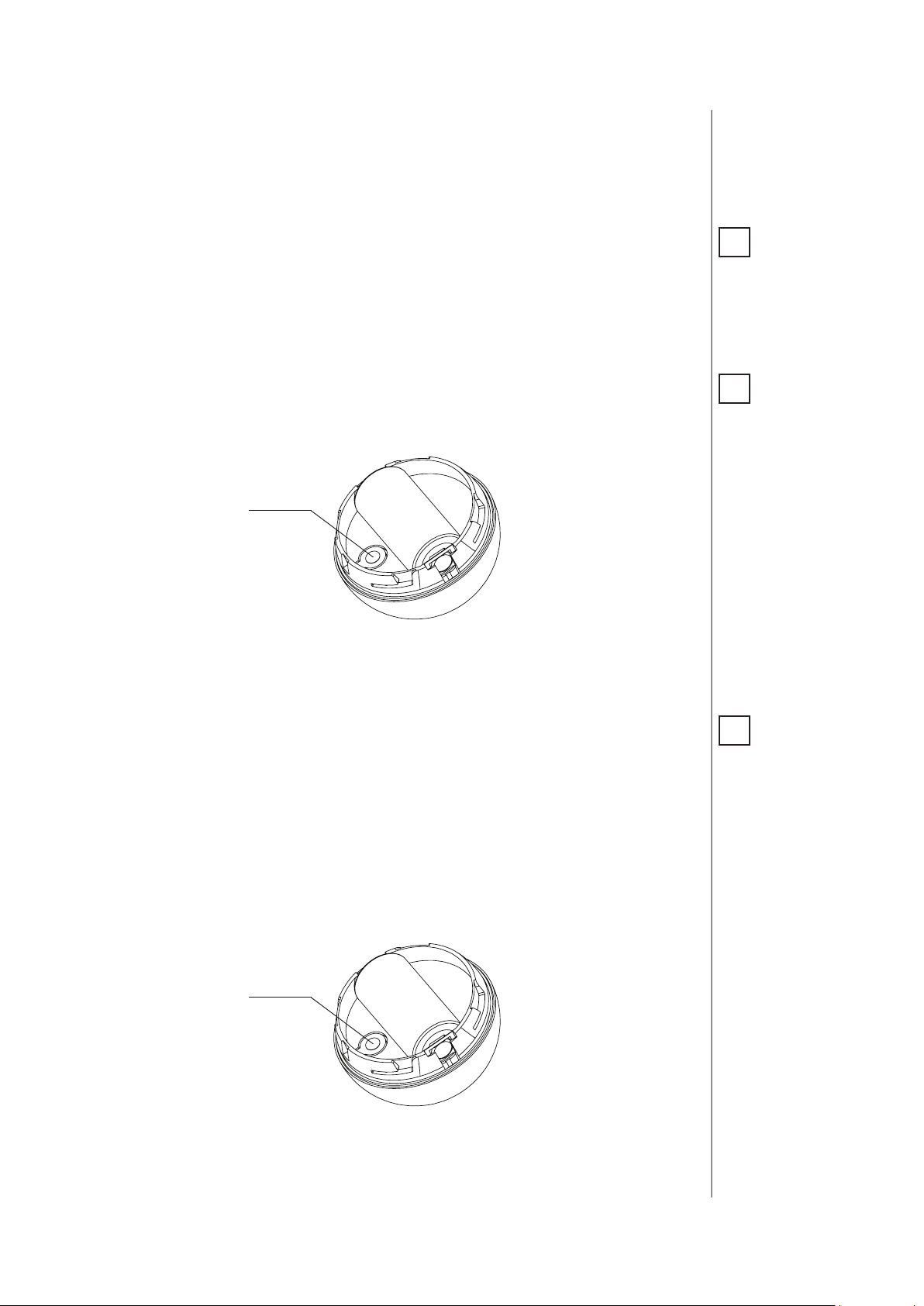
4. Quickly, three times press the B-button.
B-button
5. Wait for the adding process to end.
6. Successful adding will be conrmed by the Z-Wave controller’s
message.
NOTE
i
Adding in security
mode must be performed up to 2 meters
from the controller.
NOTE
i
In case the Sensor is
not added, please reset the Sensor and repeat the adding procedure.
Removing (Exclusion) - Z-Wave device learning mode, allowing to
remove the device from existing Z-Wave network.
To remove the device from the Z-Wave network:
1. Open the cover.
2. Place the Motion Sensor within the direct range of your Z-Wave
controller.
3. Set the main controller in remove mode (see the controller’s
manual).
4. Quickly, three times press the B-button.
B-button
5. Wait for the removing process to end.
6. Successful removing will be conrmed by the Z-Wave controller’s
message.
NOTE
i
Removing the device
from the Z-Wave network restores all the
default parameters of
the device.
ADDING/REMOVING THE DEVICE
Page 6
6
0 m
5 m
5 m
7 m
0 m
3 m
7 m
#4: Physical installation
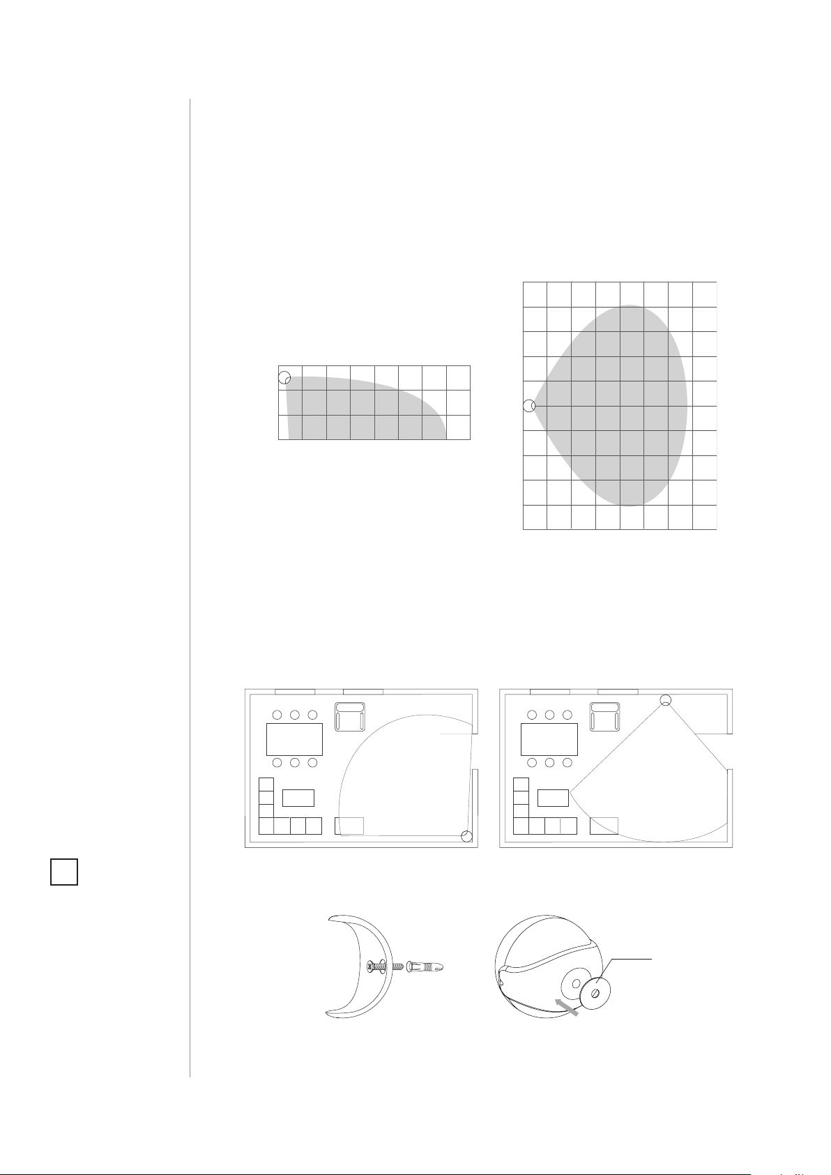
Detection range:
Detection range of the Motion Sensor is shown below. Actual range
of the Sensor can be inuenced by environmental conditions.
NOTE
i
Remember to add the
device to the Z-Wave
network prior to installation, as the adding procedure must
be performed within
the direct range of the
controller.
Installation location and working conditions:
The Motion Sensor should be installed in a corner of the room or perpendicularly to the doors.
Moving objects such as trees blowing in the wind, cars passing by,
windmills and moving masses of air and heat within detection area
of the sensor can cause false motion detection.
Installing the Motion Sensor:
1. Install the holder (using an expansion bolt or a sticker).
Sticker
2. Insert the device into the holder.
PHYSICAL INSTALLATION
3. Test the operation - check whether the device indicates motion
detection.
Page 7

#5: Operating the device
Controlling the Motion Sensor using the B-button:
The Motion Sensor is equipped with a B-button, which allows to use
the menu and additionally perform the following actions:
1x click: wake up the device or select the desired menu option (if
menu is active)
3x click: add/remove the device to/from a Z-Wave network
Holding: enter/navigate through the menu
Visual indications:
The Motion Sensor is equipped with a LED diode, signalling sensor’s
operating modes and alarms. In addition the visual indicator may inform of the Z-Wave network range and the current temperature.
7
Visual indicator signalling modes:
1. Motion Alarm colour will vary depending on the temperature. The
colour and the signalling mode can be set in parameter 80.
2. Tamper alarm is signalled with an alternating blinking in LAPD
colours (red - blue - white).
3. The Z-Wave Node Info command frame is signalled with glowing in
blue. Node Info command frame is sent each time the device wakes up.
4. Menu position is signalled with assigned illumination colour.
Menu:
Menu allows to perform Z-Wave network actions. In order to use menu:
1. Press and hold the B-button.
2. Wait for the device to indicate desired position with a colour:
• VIOLET - Z-Wave network’s range test
• YELLOW - device reset
3. Release the B-button.
4. Click the B-button to conrm selection.
Waking up the Motion Sensor:
The Motion Sensor needs to be woken up to receive information on new
congurations from the controller, like parameters and associations.
To wake up the sensor manually triple click the B-button located inside the housing.
Controlling the Motion Sensor with FIBARO Home Center controller:
The Motion Sensor has a bulit-in motion detector, temperature sensor
and light intensity sensor, which make it a multi-channel device. In the
Home Center interface it will be presented as three devices.
OPERATING THE DEVICE
Page 8

8
Seismograph mode:
The Motion Sensor can be congured to work as a simple earthquake
detector, by setting the parameter 24 value to 1. Reports with scale of
the vibrations (in the Modied Mercalli Scale) will be sent immediately after vibrations have been detected. Minimal power of vibrations
that will be reported, can be set in parametr 20. Once the vibrations
cease and time of sustaining alarm elapses, reports will be stopped.
NOTE
i
Resetting the device is
not the recommended way of removing
the device from the
Z-Wave network. Use
reset procedure only if
the primary controller
is missing or inoperable. Certain device removal can be achieved
by the procedure of
removing described in
“Adding/removing the
device” on page 6.
Orientation in space:
The Motion Sensor has a built-in accelerometer. When the parameter 24
is set to 2, Z-Wave network controller will be informed on the Sensor’s
orientation in space by sending report after triggering tamper alarm.
Resetting the Motion Sensor:
Reset procedure erases the memory, including all information on the
Z-Wave network and the main controller.
1. Open the cover.
2. Press and hold the B-button.
3. Wait for visual indicator to glow yellow (2nd menu position).
4. Release the B-button.
5. Click the B-button to conrm selection.
6. After few seconds the device will be reset, which is signalled with
the red, fading visual indicator colour.
NOTE
i
Command Class Basic
value is related to the
status of motion sensor
(0x00 - no motion, 0xFF
- motion detected).
OPERATING THE DEVICE
Notication report:
The device uses Notication Command Class to report dierent events.
Notication Type Event
Home Security Tampering, product covering removed
Home Security Motion Detection, unknown location
Page 9

#6: Association
9
Association (linking devices) - direct control of other devices within
the Z-Wave system network e.g. Dimmer, Relay Switch, Roller Shutter
or scene (may be controlled only through a Z-Wave controller).
The Motion Sensor provides the association of four groups:
1st association group – “Lifeline” reports the device status and al-
lows for assigning single device only (main controller by default).
2nd association group – “Motion” is assigned to the motion sensor
- sends Basic Set command frames to the associated devices.
3rd association group – “Tamper” is assigned to the tamper - sends
tamper alarm and alarm cancellation frames to the associated devices.
4th association group – “Motion BC” is assigned to the motion sensor - sends motion detection and alarm cancellation frames to the
associated devices. Provides backward compatibility with controllers
not supporting Z-Wave+ protocol.
5th association group – “Tamper BC” is assigned to the tamper sends tamper alarm and alarm cancellation frames to the associated
devices. Provides backward compatibility with controllers not supporting Z-Wave+ protocol.
NOTE
i
Association allows direct transfer of control
commands between
devices, is performed
without participation
of the main controller
and requires associated device to be in direct range.
The Motion Sensor in 2nd to 5th group allows to control
5 regular and 5 multichannel devices per an association group, with
the exception of “LifeLine” that is reserved solely for the controller and
hence only 1 node can be assigned.
It is not recommended to associate more than 10 devices in general,
as the response time to control commands depends on the number of
associated devices. In extreme cases, system response may be delayed.
To add an association (using the Home Center controller):
1. Go to device options by clicking the icon:
2. Select the „Advanced” tab.
3. Specify to which group and what devices are to be associated.
4. Wait for the conguration process to end. Sending relevant information to devices added to associated groups may take even a
few minutes.
5. Wake up the device manually to speed up the conguration
process.
ASSOCIATION
Page 10

10
#7: Z-Wave range test
CAUTION
!
To make Z-Wave range
test possible, the device must be added
to the Z-Wave controller. Testing may stress
the network, so it is
recommended to perform the test only in
special cases.
NOTE
i
Communication mode
of the Motion Sensor
may switch between
direct and one using
routing, especially if
the device is on the
limit of the direct
range.
The Motion Sensor has a built in Z-Wave network main controller’s
range tester.
Follow the below instructions to test the main controller’s range:
1. Open the cover.
2. Press and hold the B-button.
3. Wait for visual indicator to glow violet (1st menu position).
4. Release the B-button.
5. Click the B-button to conrm selection.
6. Visual indicator will indicate the Z-Wave network’s range (range
signalling modes described below).
7. To exit Z-Wave range test, press the B-button briey.
Z-Wave range tester signalling modes:
Visual indicator pulsing green - the Motion Sensor attempts to es-
tablish a direct communication with the main controller. If a direct
communication attempt fails, the device will try to establish a routed
communication, through other modules, which will be signalled by
visual indicator pulsing yellow.
Visual indicator glowing green - the Motion Sensor communicates
with the main controller directly.
Visual indicator pulsing yellow - the Motion Sensor tries to establish a routed communication with the main controller through other
modules (repeaters).
ZWAVE RANGE TEST
Visual indicator glowing yellow - the Motion Sensor communicates
with the main controller through the other modules. After 2 seconds
the device will retry to establish a direct communication with the
main controller, which will be signalled with visual indicator pulsing
green.
Visual indicator pulsing violet - the Motion Sensor does communicate at the maximum distance of the Z-Wave network. If connection
proves successful it will be conrmed with a yellow glow. It’s not recommended to use the device at the range limit.
Visual indicator glowing red - the Motion Sensor is not able to connect to the main controller directly or through another Z-Wave network device (repeater).
Page 11

#8: Advanced parameters
The Motion Sensor allows to customize its operation to user’s needs.
The settings are available in the FIBARO interface as simple options
that may be chosen by selecting the appropriate box.
In order to congure the Motion Sensor (using the Home Center controller):
1. Go to the device options by clicking the icon:
2. Select the „Advanced” tab.
Wake up interval
Available settings: 1-65535 (1-65535 seconds)
11
Default setting: 7200 (every 2 hours)
The Motion Sensor will wake up after each dened time interval and
always try to connect with the main controller. After a successful communication attempt, the sensor will update conguration parameters, associations and settings and will go into standby mode. After
failed communication attempt (e.g. lack of Z-Wave range) the device
will go into standby mode and retry to establish connection with the
main controller after the next time interval.
Wake up may be performed manually by a single B-button click.
Longer time interval means less frequent communication and thus a
longer battery life.
1. Motion detection - sensitivity
The lower the value, the more sensitive the PIR sensor is.
Available settings: 8-255
Default setting: 15 Parameter size: 2 [bytes]
2. Motion detection - blind time
PIR sensor is “blind” (insensitive) to motion after last detection for the
amount of time specied in this parameter.
Shorter time periods allow to detect motion more frequently, but the
battery will be drained faster.
Available settings: 0-15 (0.5-8 seconds, time [s] = 0.5 x (value+1))
Default setting: 15 Parameter size: 1 [byte]
NOTE
i
Blind time should be
shorter that the time
period set in parameter 6 (alarm cancellation delay).
ADVANCED PARAMETERS
Page 12

12
3. Motion detection - pulse counter
This parameter determines the number of moves required for the PIR
sensor to report motion. The higher the value, the less sensitive the
PIR sensor is.
It is not recommended to modify this parameter settings!
Available settings: 0 - 1 pulse
1 - 2 pulses
2 - 3 pulses
3 - 4 pulses
Default setting: 1 (2 pulses) Parameter size: 1 [byte]
4. Motion detection - window time
Period of time during which the number of moves set in parameter
3 must be detected in order for the PIR sensor to report motion. The
higher the value, the more sensitive the PIR sensor is.
It is not recommended to modify this parameter setting!
Available settings: 0 - 4 seconds
1 - 8 seconds
2 - 12 seconds
3 - 16 seconds
Default setting: 2
6. Motion detection - alarm cancellation delay
Time period after which the motion alarm will be cancelled in the
main controller and associated devices.
Any motion detected during this period resets the timer.
Available settings: 1-32767 (in seconds)
Default setting: 30 (30s) Parameter size: 2 [bytes]
8. Motion detection - operating mode
This parameter determines in which part of day the PIR sensor will be
active.
This parameter inuences only the motion reports and associations.
Tamper, light intensity and temperature measurements will be still
active, regardless of this parameter settings.
(12 seconds)
Parameter size: 1 [byte]
ADVANCED PARAMETERS
Available settings: 0 - PIR sensor always active
1 - PIR sensor active during the day only
2 - PIR sensor active during the night only
Default setting: 0 Parameter size: 1 [byte]
Page 13

9. Motion detection - night/day
This parameter denes the dierence between night and day in terms
of light intensity, used in parameter 8.
Available settings: 1-32767 (1-32767 lux)
Default setting: 200 (200 lux) Parameter size: 2 [bytes]
13
12. BASIC command class conguration
This parameter determines the command frames sent to 2nd association group (assigned to PIR sensor).
Available settings: 0 - BASIC ON and OFF command frames sent in
Basic Command Class
1 - only the BASIC ON command frame sent in
Basic Command Class
2 - only the BASIC OFF command frame sent in
Basic Command Class
Default setting: 0 Parameter size: 1 [byte]
14. BASIC ON command frame value
The command frame sent at the moment of motion detection. Further motion detections, during the cancellation time, will not result
in sending the association.
Available settings: 0-255
Default setting: 255 Parameter size: 2 [byte]
16. BASIC OFF command frame value
NOTE
i
Values of BASIC ON
and BASIC OFF command frames can be
modied with dedicated parameters (14
and 16).
The command frame sent at the moment of motion alarm cancellation, after cancellation delay time specied in parameter 6.
Available settings: 0-255
Default setting: 0 Parameter size: 2 [bytes]
18. Associations in Z-Wave network Security Mode
This parameter denes how commands are sent in specied association groups: as secure or non-secure. Parameter is active only in Z-Wave
network security mode. It does not apply to 1st group “Lifeline”.
Available settings: 0 - none of the groups sent as secure
1 - 2nd group sent as secure
2 - 3rd group sent as secure
4 - 4th group sent as secure
8 - 5th group sent as secure
Default setting: 15 Parameter size: 1 [byte]
ADVANCED PARAMETERS
Page 14

14
20. Tamper - sensitivity
This parameter determines the change in force acting on the device,
that will result in reporting tamper alarm - g-force acceleration.
Available settings: 0 - tamper inactive
1-121 - (0.08-2g; every 0.016g)
Default setting: 20 (0.4g) Parameter size: 1 [byte]
22. Tamper - alarm cancellation delay
Time period after which a tamper alarm will be cancelled in the main
controller and associated devices.
Any tampering detected during this period will not extend the delay.
Available settings: 1-32767 (in seconds)
Default setting: 30 (30s) Parameter size: 2 [bytes]
24. Tamper - operating modes
This parameter determines function of the tamper and sent reports.
It is an advanced feature serving much more functions than just detection of tampering.
NOTE
i
Device operating in
Security Mode does
not send frames in
broadcast mode. In
this case leave the default values of parameters 28 and 29.
Available settings: 0 - tamper only
1 - tamper and earthquake detector
2 - tamper and orientation in space
Default setting: 0 Parameter size: 1 [byte]
25. Tamper - alarm cancellation
This parameter allows to disable cancellation of the tamper alarm.
Available settings: 0 - do not send tamper cancellation report
1 - send tamper cancellation report
Default setting: 1 Parameter size: 1 [byte]
28. Tamper - broadcast mode
The parameter determines whether the tamper alarm frame will or
will not be sent in broadcast mode. Alarm frames sent in broadcast
mode can be received by all of the devices within range (if they accept such frames), but not repeated by them.
Available settings: 0 - tamper alarm sent to 3rd association group
1 - tamper alarm sent in broadcast mode
ADVANCED PARAMETERS
Default setting: 0 Parameter size: 1 [byte]
29. Tamper - backward compatible broadcast mode
The parameter determines whether the backward compatible tamper alarm frame will or will not be sent in broadcast mode. Alarm
frames sent in broadcast mode can be received by all of the devices
within range (if they accept such frames), but not repeated by them.
Page 15

This parameter provides backward compatibility with controllers not
supporting Z-Wave+.
Available settings: 0 - backward compatible tamper alarm sent to
5th association group
1 - backward compatible tamper alarm sent in
broadcast mode
Default setting: 0 Parameter size: 1 [byte]
40. Illuminance report - threshold
This parameter determines the change in light intensity level resulting in illuminance report being sent to the main controller.
Available settings: 0 - reports are not sent
1-32767 (illuminance in lux)
Default setting: 200 (200 lux) Parameter size: 2 [bytes]
15
42. Illuminance report - interval
Time interval between consecutive illuminance reports. The reports
are sent even if there is no change in the light intensity.
Available settings: 0 - periodical reports are not sent
1-32767 (in seconds)
Default setting: 3600 (1h) Parameter size: 2 [bytes]
60. Temperature report - threshold
This parameter determines the change in measured temperature that
will result in new temperature report being sent to the main controller.
Available settings: 0 - reports are not sent
1-255 (0.1-25.5°C, 0.1°C step)
Default setting: 10 (1°C) Parameter size: 2 [bytes]
62. Temperature measuring - interval
Time interval between consecutive temperature measurements. The
shorter the time, the more frequently the temperature will be measured, but the battery life will shorten.
Available settings: 0 - temperature is not measured
1-32767 (in seconds)
Default setting: 900 (900s) Parameter size: 2 [bytes]
NOTE
i
Frequent illuminance
reports will shorten
the battery life. Parameter value under
5 may result in blocking the temperature
reports.
NOTE
i
Temperature measurements are still
performed during the
wake up, even if the
periodic measuring is
disabled (parameter
62 set to 0).
64. Temperature report - interval
Time interval between consecutive temperature reports. The reports
are sent even if there is no change in the temperature.
Available settings: 0 - periodical reports are not sent
1-32767 (in seconds)
Default setting: 0 Parameter size: 2 [bytes]
NOTE
i
Frequent temperature
reports will shorten
the battery life. Parameter value under
5 may result in blocking the illuminance
reports.
ADVANCED PARAMETERS
Page 16

16
66. Temperature oset
The value to be added to the actual temperature, measured by the
sensor (temperature compensation).
Available settings: -1000 - 1000 (-100 - 100°C, 0.1°C step)
Default setting: 0 (0°C) Parameter size: 2 [bytes]
NOTE
i
Flashlight Mode visual indicator glows
in white for 10 seconds. If value of parameter 80 is set to 11,
each detected motion
extends the glowing
by next 10 seconds.
80. Visual LED indicator - signalling mode
This parameter determines the way in which visual indicator behaves
after motion has been detected.
Available settings: 0 - LED inactive,
Values from 1 to 9 - single long blink at the moment of reporting motion. No other motion will
be indicated until alarm is cancelled.
1 - colour is temperature dependent,
2 - Flashlight Mode, 3 - white, 4 - red, 5 - green,
6 - blue, 7 - yellow, 8 - cyan, 9 - magenta
Values from 10 to 18 - single long blink at the
moment of reporting motion and one short
blink each time the motion is detected again.
10 - colour is temperature dependent,
11 - Flashlight Mode, 12 - white, 13 - red,
14 - green, 15 - blue, 16 - yellow, 17 - cyan,
18 - magenta
Values from 19 to 26 - single long blink at the
moment of reporting motion and two short
blinks each time the motion is detected again.
CAUTION
!
The value of parameter 83 must be higher
than the value of parameter 82.
19 - colour is temperature dependent,
20 - white, 21 - red, 22 - green, 23 - blue,
24 - yellow, 25 - cyan, 26 - magenta
Default setting: 10 Parameter size: 1 [byte]
81. Visual LED indicator - brightness
This parameter determines the brightness of the visual LED indicator
when indicating motion.
Available settings: 0 - brightness determined by the illuminance
(parameters 82 and 83)
1-100 (1-100%)
Default setting: 50 (50%) Parameter size: 1 [byte]
82. Visual LED indicator - illuminance for low indicator brightness
Light intensity level below which brightness of visual indicator is set
to 1%.
Available settings: 0 to value of parameter 83 (in lux)
Default setting: 100 Parameter size: 2 [bytes]
ADVANCED PARAMETERS
Page 17

83. Visual LED indicator - illuminance for high indicator brightness
Light intensity level above which brightness of visual indicator is set
to 100%.
Available settings: value of parameter 82 to 32767 (in lux)
Default setting:
86. Visual LED indicator - temperature for blue colour
This parameter determines minimal temperature that will result in
blue visual indicator colour. Relevant only when parameter 80 has
been properly congured.
Available settings: 0 to value of parameter 87 (in Celsius degree)
Default setting:
87. Visual LED indicator - temperature for red colour
This parameter determines minimal temperature that will result in red
visual indicator colour. Relevant only when parameter 80 has been
properly congured.
1000
18 (18
°C) Parameter size: 2 [bytes]
Parameter size: 2 [bytes]
17
Available settings: value of parameter 86 to 255 (in Celsius degree)
Default setting:
89. Visual LED indicator - tamper alarm
This parameter allows to enable/disable indicating tamper alarm
(ashing white, red and blue)
Available settings: 0 - tamper alarm is not indicated
Default setting:
28 (28
°C) Parameter size: 2 [bytes]
1 - tamper alarm is indicated
1
Parameter size: 1 [byte]
ADVANCED PARAMETERS
Page 18

18
#9: Specications
CAUTION
!
Using batteries other
than specied may
result in explosion.
Dispose of properly,
observing environmental protection
rules.
NOTE
i
Radio frequency of
individual device
must be same as your
Z-Wave controller.
Check information
on the box or consult
your dealer if you are
not sure.
Power supply:
Battery type:
EU directives compliance:
Radio protocol:
Radio frequency:
Range:
Recommended
installation height:
Operating temperature:
Temperature measuring
range:
Temperature measuring
accuracy:
Illuminance measuring
range:
Dimensions (diameter):
3.0V DC battery
CR123A
RoHS 2011/65/EU
RED 2014/53/EU
Z-Wave (500 series chip)
868.4 or 869.8 MHz EU;
908.4, 908.42 or 916.0 MHz US;
921.4 or 919.8 MHz ANZ;
869.0 MHz RU;
up to 50m outdoors
up to 40m indoors
(depending on terrain and building
structure)
2.4 meters
0-40°C
-20-100°C
0.5°C (within 0-40°C range)
0-32000 lux
46 mm
SPECIFICATIONS
Page 19

#10: Regulations
This device complies with Part 15 of the FCC Rules
Operation is subject to the following two conditions:
1. This device may not cause harmful interference
2. This device must accept any interference received, including interference that may cause undesired operation. This equipment has been
tested and found to comply with the limits for a Class B digital device,
pursuant to part 15 of the FCC Rules. These limits are designed to provide reasonable protection against harmful interference in a residential installation. This equipment generates, uses and can radiate radio
frequency energy and, if not installed and used in accordance with the
instructions, may cause harmful interference to radio communications.
However, there is no guarantee that interference will not occur in a particular installation. If this equipment does cause harmful interference
to radio or television reception, which can be determined by turning
the equipment o and on, the user is encouraged to try to correct the
interference by one or more of the following measures:
• Reorient or relocate the receiving antenna.
• Increase the separation between the equipment and receiver.
• Connect the equipment into an outlet on a circuit dierent from
that to which the receiver is connected.
• Consult the dealer or an experienced radio/TV technician for help.
19
Changes and modications not expressly approved by the manufacturer or registrant of this equipment can void your authority to operate
this equipment under Federal Communications Commission’s rules.
Industry Canada (IC) Compliance Notice
This device complies with Industry Canada license-exempt RSSs. Operation is subject to the following two conditions: (1) this device may
not cause interference, and (2) this device must accept any interference, including interference that may cause undesired operation of the
device.
Cet appareil est conforme aux normes d’exemption de licence RSS d’Industry Canada. Son fonctionnement est soumis aux deux conditions
suivantes : (1) cet appareil ne doit pas causer d’interférence et (2) cet
appareil doit accepter toute interférence, notamment les interférences
qui peuvent aecter son fonctionnement.
Legal Notices
All information, including, but not limited to, information regarding the
features, functionality, and/or other product specication are subject
to change without notice. Fibaro reserves all rights to revise or update its products, software, or documentation without any obligation to
notify any individual or entity.
FIBARO and Fibar Group logo are trademarks of Fibar Group S.A. All
other brands and product names referred to herein are trademarks of
their respective holders.
REGULATIONS
Page 20

20
DGT Warning Statement
Article 12
Without permission, any company, rm or user shall not alter the frequency, increase the power, or change the characteristics and functions
of the original design of the certied lower power frequency electric
machinery.
Article 14
The application of low power frequency electric machineries shall not
aect the navigation safety nor interfere a legal communication, if an
interference is found, the service will be suspended until improvement
is made and the interference no longer exists.
第十二條
經型式認證合格之低功率射頻電機,非經許可,公司、商號或使用
者均不得擅自變更頻率、加大功率或變更原設計之特性及功能。
第十四條
低功率射頻電機之使用不得影響飛航安全及干擾合法通信;經發現
有干擾現象時,應立即停用,並改善至無干擾時方得繼續使用。
前項合法通信,指依電信法規定作業之無線電通信。
低功率射頻電機須忍受合法通信或工業、科學及醫療用電波輻射性
電機設備之干擾。
Warning
This product is not a toy. Keep away from children and animals!
Information according REACH
The included Panasonic CR123A battery contains 1,2-Dimethoxyethane substance. Normal use of the device does not expose the user to
a given substance.
Declaration of conformity
Hereby, Fibar Group S.A. declares that the device is in compliance with
the essential requirements and other relevant provisions of Directive
2014/53/EU. The full text of the EU declaration of conformity is available
at the following internet address: www.manuals.baro.com
WEEE Directive Compliance
Device labelled with this symbol should not be disposed with other
household wastes. It shall be handed over to the applicable collection
point for the recycling of waste electrical and electronic equipment.
REGULATIONS
 Loading...