

Page 1

INTERCOM
SMART VIDEO DOORBELL
Installation & Configuration Guide
Page 2

Important safety information
!
Read this manual before attempting to install the device!
Failure to observe recommendations included in this manual may be dangerous or cause a violation of the law. The manufacturer, Fibar
Group S.A. will not be held responsible for any loss or damage resulting from not following the instructions of operating manual.
The manufacturer is not responsible for any accidents related to theft, damage or breaching of the wiring, performed by an unauthorized
person.
The device is not designed to protect the owner’s property. It is recommended to use a professional alarm system for such solution.
Make sure that local law does not prohibit to record, store, and edit the video without the consent of people being recorded.
It is strongly prohibited to connect any of the device terminals to mains (110V/230V) voltage! It is designed to be powered with low volt-
age power supply. Connecting to the mains power will result in damaging the device and will void the warranty.
To be installed only by a qualied specialist! Performing the installation or maintenance on your own may void the warranty.
Please note that the usage of cellular data may cause additional charge.
Caution HOT!
Inside the operating device there are elements that may cause burns. The device may be demounted at least 30 minutes after
disconnecting the power supply. We recommend to still watch for elements marked as “Caution hot”.
Page 3

CONTENTS
Description and features
Installation
Package contents
Required equipment
Choosing location
Choosing and routing wires
Mounting the installation box
Mounting the in-wall part
Connecting wires
Mounting the on-wall part
SD Card
Conguration
Requirements
First login
Creating home
Conguration of the rst device
Connecting to the network
User conguration
Adding more devices
User roles
Inviting users
Resetting to factory settings
Device operation
Use cases
Specications
Regulations
Warranty terms and conditions
4
5
5
6
7
8
10
11
12
15
16
17
17
18
19
19
20
21
22
22
23
24
25
26
28
29
30
Page 4

Description and features
Description
FIBARO Intercom can show you everyone who has arrived at your doorstep with a 180-degree high-denition view and night vision.
This modern-looking, high-gloss device can be placed near the front door or gate to look after your safety.
The Intercom allows to control two gates, which might be opened using assigned PIN codes on rotating ring, holding up a phone towards
the device or using dedicated app to do it remotely.
The recordings can be stored on a SD card.
Main features
• Rotating ring used for PIN codes,
• Two relay outputs (to control gates),
• Full HD video resolution (1080p/30fps),
• Ultra-wide angle lens (180o),
• IR illumination (for night view),
• Noise-canceling microphones,
• Speaker,
• Proximity sensor.
Before installing the device
1) Check if the package content is complete,
2) Prepare all the required equipment,
3) Make sure the power is o.
4 DESCRIPTION AND FEATURES
Page 5
Installation
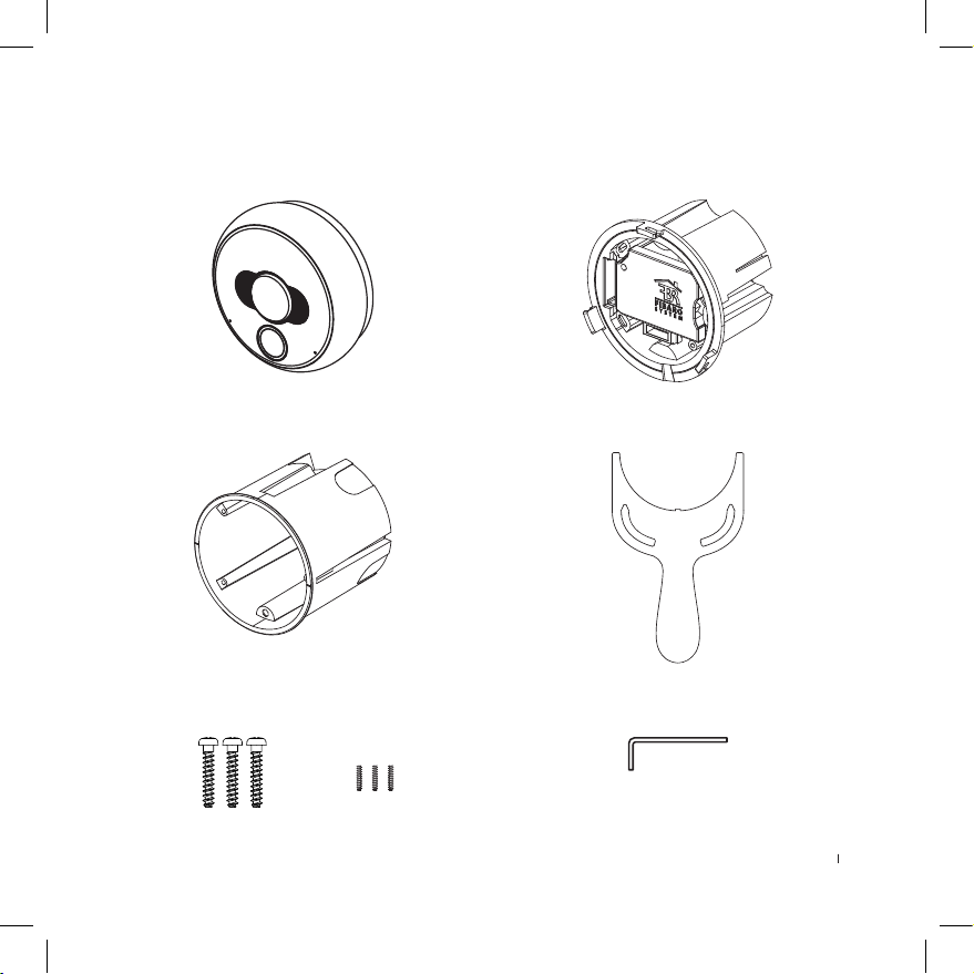
Package contents
On-wall part
In-wall part
Installation box
Mounting screws
2.2mm x 12mm
M2 x 8mm
DIN 913 hex
Tightening tool
Hex key 0.9mm
5INSTALLATION PACKAGE CONTENTS
Page 6
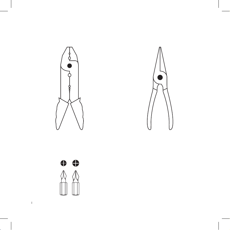
Required equipment
Wire stripper
PH0 and PH1 Phillips Screwdrivers
Needle-Nose Pliers or Tweezers
Professional equipment for mounting
the installation box depending on the
type of construction material
6 INSTALLATION REQUIRED EQUIPMENT
Page 7
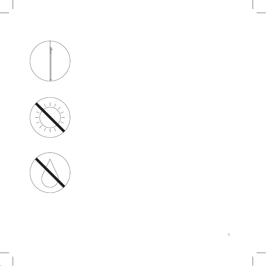
Choosing location
Recommended height of installation: 160 cm
Do not install the device in direct sunlight!
If this happens, try to shade the device to avoid overheating and to keep the sun
o the lens and reduce are.
Long-term operating in direct sunlight may cause overheating of the device, its
malfunctioning, and a signicant temperature rise of a housing above the limit of
safe operation for the user.
Do not mount the device in places exposed to rain or water drop, or prone to
ooding.
Surface around the installation box should be perfectly smooth to ensure aligning the device with the wall.
INSTALLATION CHOOSING LOCATION
7
Page 8

Choosing and routing wires
i
The device may be powered in two ways:
1) Power supply 12V DC (+/- 10%) 1A LPS (not included)
2) PoE (Power over Ethernet) PSE 48V
Both powering modes work in parallel and may be connected at the same time with no eect on the device operation.
The device may be connected to network in two dierent ways:
1) Ethernet - wired connection (recommended)
2) Wi-Fi - wireless connection
Wired connection is recommended, but if you decided to use Wi-Fi connection make sure that the device will be in range of your
router and have a good quality connection.
Before routing the wires make sure what you want to connect and how many wires you will need:
1) Power supply 12V DC - used to power the device with external power supply.
Wires required: 2
2) Ethernet - used for communication with the device and can be also used to power it using PoE Power over Ethernet.
Wires required: 1 twisted pair cable with 8 wires
3) Built-in relays - can be used to open 2 gates or doors with an electric lock (via app, BLE proximity function, PIN code or physical buttons).
Wires required: 2 wires per one gate/door
4) Two buttons for built-in relays - can be used to control built-in relay using physical buttons, switches etc.
Wires required: 1 wire per one button and 1 wire for common ground
5) Tamper - can be connected to an external system to alarm it in case of sabotage attempt.
Wires required: 2
INSTALLATION CHOOSING AND ROUTING WIRES
8
Page 9

When routing wires take into consideration:
• The installation wires of the unit must be lead separately from the mains power wires to prevent the transmission interference and
overvoltage on the control lines.
• Wires inside the installation boxes should be as short as possible to prevent curling the wires and allow for easy assembling of the
in-wall part.
• Installation wires should be carried securely and not visible from the outside, preventing from the interference by unauthorized person.
• Recommended Ethernet cable for network connection is a twisted pair cable CAT-5e. The maximum cable length is 100 meters.
• Other inputs should be connected using the solid-core wires with cross-section from 0.14 to 0.34 mm2 (26…22 AWG). Connectors are
also capable of connecting stranded wires.
• Close vicinity of mains (110V/230V) electrical wires may cause deterioration of the transmission through the Internet and potential
noise on the inputs.
INSTALLATION CHOOSING AND ROUTING WIRES
9
Page 10
Mounting the installation box
i
Before installation pay attention to:
• Installation box must be mounted using the materials which will
not cause the tension that could deform the shape of a box after
the installation (e.g. by expanding).
• Mounting in the drywall requires using screws with hooks (not
included).
• Mounting in the insulation-lled wall (e.g. drywall with mineral
wool) requires to keep at least 10cm distance from the insulation
to prevent the device from overheating.
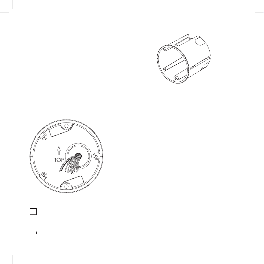
To install the box:
1) Prepare hole for 65mm x 75mm (diameter x depth) installation box.
2) Route cables to the back of the hole (see “Choosing and routing wires” on page 8).
3) Drag the cables through the rubber sealing on the back of the box, taking care to keep the tightness.
4) Mount the box in the hole and align it so the TOP arrow points up.
5) Make sure the box is ush with the wall and rmly attached.
It is recommended to use the plasterboard adhesive (type T) to securely install the box.
INSTALLATION MOUNTING THE INSTALLATION BOX
10
Page 11

Mounting the in-wall part
To install the in-wall part:
1) Use a screwdriver to unscrew the small screw that secures the
masking cap labelled with FIBARO logo.
2) Drag the wires through the hole located on the right of the inwall part.
3) Place the in-wall part of the device inside the installation box.
4) Using three attached screws fasten the part with the box, make
sure it is aligns properly and adjoins the wall.
INSTALLATION MOUNTING THE INWALL PART
11
Page 12

Connecting wires
5
4cm
4cm
5mm
i
To connect the wires:
1) Make sure that no wires are powered.
2) Remove the outer insulation to expose about 5 cm of the insulated inner wires, taking care not to damage them.
3) Separate and straighten the inner wires if twisted.
4) Cut the inner wires to 4 cm in length.
5) Remove the insulation from the inner wires to leave about 5 mm of exposed metal core on each wire.
6) Put the wires inside the terminals using long-nose pliers or tweezers according to diagrams below.
7) Make sure all wires are rmly attached.
Should you need to remove a wire from the connector we recommend to use a dedicated tool - WAGO 2059-189 (not included,
shown below) to minimize the risk of connectors damage.
12 INSTALLATION CONNECTING WIRES
Page 13

Connecting ethernet/POE cable:
ETH1-ETH8 inputs are related to specied numbers of wires in RJ-45
connector according to the T-568B standard as shown below.
o O g B b G br BR
Connecting 12V DC power supply:
Inputs for connecting an external 12V DC power supply. Please
double-check correct polarity of power supply.
12V
GND
CAUTION
!
Before connecting the power supply, or attaching the wires to device terminals, make sure that the power supply and installation
complies with the limits of current and voltage.
Use only Class II or double insulated power supplies and peripheral devices which provide operating in SELV (Safety Extra Low
Voltage) circuits.
13INSTALLATION CONNECTING WIRES
Page 14

Connecting relays:
Congurable relay outputs 30V/1A. Outputs are not designed for
long-term supplying of external devices. Contacts are not connected to the ground and can be connected with any polarity.
R2 R2R1 R1
Connecting buttons for relays:
Congurable dry contact logic inputs designed to be operated by
reed sensors, switches, and relay outputs.
N1
GND
N2
14 INSTALLATION CONNECTING WIRES
Connecting tamper switch to external system:
Anti-sabotage input, used for connecting to the external alarm
system. Normally opened contacts close after installing the
external, on-wall part of the device. Contacts are not connected to the ground and can be connected with any polarity.
Parameters: max. 12VDC/50mA.
TMP
TMP
To nd more information about potential use cases of each type of
connection see “Use cases“ on page 26.
Page 15

Mounting the on-wall part
To mount the on-wall part:
1) Install the masking cap and tighten it with a screw.
2) At this moment you can install a SD card (see “SD Card” on page
16 for more information).
3) Insert the on-wall part (metal at plate should be on the left) and
align it without using excessive force.
4) While holding the on-wall part, turn the inner black ring counter-clockwise using the included tightening tool until you feel
resistance.
5) Using the included hex key, tighten the small hex screw until it
ushes with the black ring (look at the picture on the right). Be
careful not to cause its deformation.
6) The device is ready to work. You can turn on the mains power and
move to device conguration guide.
INSTALLATION MOUNTING THE ONWALL PART
15
Page 16

SD Card
The device allows for installing the microSD Card for local storage of recordings.
FIBARO Intercom supports up to 128 GB microSDHC and microSDXC cards, Class 10 is recommended.
As for recording time, please refer to below chart.
Inserting a memory card:
1) Before inserting the microSD Card, please ensure the direction is
correct, otherwise the card and card slot may be damaged!
2) Open the plastic cover located behind the ring.
3) Use your nger to pull forward the latch that keeps the SD card
in place.
4) Lift the latch up.
5) Place the SD card into the slot with the label side facing up and
the gold contacts toward the slot.
6) Close the latch and pull it back until you feel a click.
7) Close the plastic cover.
Memory card capacity chart
128 GB
128 GB
Resolution
Storage
8 GB 16 GB 32 GB 64 GB 128 GB
1080p (1920 x 1080) 10h 19h 39h 77h 155h
720p (1280 x 720) 17h 35h 69h 139h 277h
576p (720 x 576) 25h 50h 99h 198h 395h
288p (352 x 288) 69h 139h 278h 555h 1110h
16
INSTALLATION SD CARD
Page 17

Conguration
i
i
i
Requirements
After proper installation of the FIBARO Intercom to run the device you need a:
• iOS mobile device connected to the Wi-Fi,
• FIBARO Intercom App,
• FIBARO ID account (which you can set up during the conguration process).
Make sure that during the conguration of FIBARO Intercom your smartphone is connected to the same network as your device.
During the setup stand close to the device.
Your network should be connected to the Internet at least for the conguration time.
Download FIBARO Intercom app from the App Store
https://www.baro.com/intercom/ios
17CONFIGURATION REQUIREMENTS
Page 18

First login
Having a valid FIBARO ID account is necessary to use your device. Such account may be created through the same app that is
designed to operate the Intercom. Look below and follow one of the procedures.
Without existing FIBARO ID account:
1) Launch a downloaded FIBARO Intercom app.
2) Type in your e-mail address.
3) Set a password to be used for your FIBARO ID account.
4) Read the Terms of Service and Privacy Policy.
5) Verify your e-mail address by clicking a link provided in the message.
6) After creating an account, move to Creating home.
With existing FIBARO ID account:
1) Launch a downloaded FIBARO Intercom app.
2) Log in to your FIBARO ID account.
3) After successful login, you go directly to Creating home.
18 CONFIGURATION FIRST LOGIN
Page 19

Creating home
i
i
In this step, it is possible to create a new home or login to existing one.
Conguration takes place through BLE (Bluetooth Low Energy) protocol.
Make sure that Bluetooth is enabled on your smartphone.
Create new home:
1) Create a home and name it.
2) Tap Next to move to Conguration of the rst device in Home section.
If you log in to existing home, just select it from the list and proceed to the next step.
Conguration of the rst device
1) Stand close to the device.
2) Make sure that your smartphone is connected through Wi-Fi to the same network and Bluetooth connection is enabled.
3) After opening the app, you will see the list of devices waiting for conguration.
You can see the strength of BLE signal. If the signal is too weak, try to come closer to the device.
4) Choose the right device and name it if you want. Then, the next step is Connecting to the network.
CONFIGURATION CREATING HOME & CONFIGURATION OF THE FIRST DEVICE
19
Page 20

Connecting to the network
i
i
i
i
After selecting your Intercom from the list, you can establish a network connection.
You can do this in three ways: via Wi-Fi or LAN (automatically or manually).
Wi-Fi connection
Make sure that the range of Wi-Fi signal is good enough. If the Intercom is located far from Wi-Fi router,
it is strongly recommended to use Wi-Fi signal expanders nearby the Intercom.
1) Select Connecting via Wi-Fi.
2) Choose your Wi-Fi network from the list.
3) You can choose the network from the list or set it up manually.
The list shows Wi-Fi networks in Intercom range. It is not a list of networks found by your phone.
4) Provide a password to the network.
5) It is also possible to set up Wi-Fi connection manually. Provide credentials of your network.
Automatic LAN connection
After successful connection Wizard takes you straight to User Conguration.
Manual LAN connection
Provide necessary credentials: IP Address, Subnet mask, Gateway, and DNS. After that go to User Conguration.
After successful conguration of the device (resulting in streaming the live view from the Intercom) it is strongly recommended to
assign a xed IP address of the device in your router. It makes the device integration easier.
If the connection with the device is not successful, it may be necessary to reset your device to factory settings. Reset procedure is
described in “Resetting to factory settings“ on page 24.
CONFIGURATION CONNECTING TO THE NETWORK
20
Page 21

User conguration
i
i
i
User conguration is necessary every time the rst device is congured at home.
User congured in this step becomes administrator of the system.
To congure a new user:
1) Type in your name in provided form and tap Next.
2) Set your photo. You can choose it from the library or use camera.
3) Set up your PIN Code to be used for opening the gate.
4) Set your password for local access.
Local password is obligatory when you use device in network without Internet access, stream camera image and you want to
integrate it with FIBARO Home Center.
Conguration summary
The following information will be displayed as a summary of the conguration process:
• Intercom name - given name of a device
• User name - name of the main user
• PIN Code - protection code set during conguration
• Local password - user password for local access
• Network - connection mode and name of network
Verify user information and tap Finish.
CONFIGURATION USER CONFIGURATION
21
Page 22

Adding more devices
i
In case of installation of several devices in your house, it is possible to add another device to your home.
To add another device:
1) Go to Settings.
2) Find Devices section.
3) Tap Add Device button.
The conguration of following devices should process same as setting up of the rst device.
One step will be omitted - Conguration of the user.
All devices assigned to one Home should operate in the same network and must be connected in the same way (Wi-Fi or LAN).
User roles
There are three user roles available in FIBARO Intercom interface:
1) Administrator - can congure home, add and change settings of devices and add or invite users. The administrator can fully utilize the
system (calling, opening the gate, history of actions).
2) System user - can use the device (calling, opening the gate, history of actions) and manage account’s settings (set and change name,
photo, and PIN).
3) PIN user - can only open the gate though account’s PIN.
22
CONFIGURATION ADDING MORE DEVICES & USER ROLES
Page 23

Inviting users
i
i
To invite new user:
1) Go to Settings.
2) Find Users section.
3) Tap Invite User button.
4) Fill the FIBARO ID user’s e-mail address in the form.
5) After sending an invitation, new user will be visible on the list.
You can only invite active FIBARO ID users.
On invited user’s behalf:
1) Install FIBARO Intercom App and log in to the FIBARO ID account (the same that the invitation was sent to).
2) After logging in you can see a Home list and the one that user is invited to will be marked.
3) After choosing a home, the next step is User Conguration.
Invited user’s permissions is system user by default. To become an administrator, the permissions must be granted by administrator
himself.
23CONFIGURATION INVITING USERS
Page 24

Resetting to factory settings
There are two ways of performing the reset of the device: through the mobile app or directly using the device. After completion, the
Intercom will be restored to factory settings. Please notice that all stored recordings will also be removed!
To reset the device through mobile app:
1) Open the app.
2) Go to Settings.
3) Select your device.
4) Find Status and tap it.
5) Tap Reset to factory button.
To reset the device directly:
1) Press and hold the ring and the button at the same time for about 10 seconds.
2) Release both when the device glows in red.
3) Enter the serial number using the rotating ring. Conrm each number with a short press of the ring.
4) Entering correct serial number will be conrmed by glowing in green and restarting.
CONFIGURATION RESETTING TO FACTORY SETTINGS
24
Page 25

Device operation
i
i
FIBARO Intercom allows to use rotating ring for entering PIN Codes set during the conguration process.
Correctly entered PIN code may result in authenticating the user and opening the gate.
Anyone who does not have a PIN code may use the button on the front to make a call.
To open the gate using the ring:
1) Move your hand close to the device - the button will light up in blue.
2) Rotate the ring to select the rst digit of your PIN code - numbers will light up one by one.
3) Push the ring to conrm selected digit.
4) Correct entering of the digit will be conrmed by turning o the backlight.
5) Enter next digits of your PIN code in the same way. If you entered incorrect digit, pull the ring to cancel the entire sequence and start
again from the 1st digit.
6) After selecting the last, 4th digit, make a single push to open the gate connected to the rst relay (R1).
Make a double push to open the gate connected to the second relay (R2).
7) The PIN code will be veried. In case of successful verication, all diodes will blink green ve times and the gate will be opened.
8) Entering incorrect PIN code will be indicated by two blinks in red.
The default time for which the gate stays opened is 3 seconds. Its length may be adjusted by the admin through the mobile app.
The gate may be opened by using the Bluetooth low energy proximity sensor. In order to do so, move your paired smartphone with
enabled Bluetooth connection close to the device.
To make a call:
1) Move your hand close to the device - the button will light up in blue.
2) Press the button.
3) LED diodes will start ashing - wait for a call.
4) If no one responds to your call, you will be able to leave your message in the voice mail.
Voice mail functionality:
Enabling the voice mail is indicated by the red button backlight, numbers ashing in red, and a beep.
Maximum length of the voice message is 30 seconds.
25DOORBELL MODE
Page 26

Use cases
• Opening the gate with electromagnetic lock through the app
GNDN1GNDN2TMP
TMP
R2 R2R1 R112V
+
12/24V
-
• Opening the gate through the wall switch at your home or near the exit
GNDN1GNDN2TMP
TMP
R2 R2R1 R112V
+
12/24V
-
• Connecting external alarm device
GNDN1GNDN2TMP
ALARM
SYSTEM
TMP
R2 R2R1 R112V
26 USE CASES
Page 27

• One switch for opening the wicket, another one for opening the gate
GNDN1GNDN2TMP
TMP
R2 R2R1 R112V
12/24V
12/24V
+
-
+
-
230VAC
+
-
USE CASES
27
Page 28

Specications
Power supply:
DC supply parameters:
PoE parameters (PSE):
Power consumption:
Conductor cross-section:
Communication protocols:
Ethernet cable category:
Recommended minimum Internet
connection bandwidth:
Terminals:
N1, N2
TMP
R1, R2
Operating temperature:
IP protection class:
External dimensions of on-wall part (Ø x depth):
Installation box dimensions (Ø x depth):
Weight:
12V DC and/or 48V PoE
12V +/- 10%, 1A LPS
36-57V, 350mA (802.3af, Class 0)
up to 5W
0.14 ... 0.34 mm²
(AWG 26 ... AWG 22)
Ethernet 10/100BASE-TX, Wi-Fi a/b/g/n 2.4/5GHz,
Bluetooth® low energy
CAT-5e
5 Mbit/s upload speed
5 Mbit/s download speed
NC, max. 5V/1mA, dry contact
NC, max. 12V DC/50mA, isolated
max. 30V/1A (SELV), relay
-30°C – 40°C
IP54
85 x 37 mm
65 x 75 mm
370g
28 SPECIFICATIONS
Page 29

Regulations
Legal Notices
All information, including, but not limited to, information regarding the features, functionality, and/or other product specication are
subject to change without notice. Fibar Group S.A. reserves all rights to revise or update its products, software, or documentation without
any obligation to notify any individual or entity.
FIBARO and Fibar Group logo are trademarks of Fibar Group S.A.
Wi-Fi is a registered trademark of Wi-Fi Alliance.
The Bluetooth word mark is registered trademark of Bluetooth SIG, Inc.
All other brands and product names referred to herein are trademarks of their respective holders.
MPEG-4 AVC
THIS PRODUCT IS LICENSED UNDER THE AVC PATENT PORTFOLIO LICENSE FOR THE PERSONAL USE OF A CONSUMER OR OTHER USES IN
WHICH IT DOES NOT RECEIVE REMUNERATION TO
(i) ENCODE VIDEO IN COMPLIANCE WITH THE AVC STANDARD (“AVC VIDEO”) AND/OR
(ii) DECODE AVC VIDEO THAT WAS ENCODED BY A CONSUMER ENGAGED IN A PERSONAL ACTIVITY AND/OR WAS OBTAINED FROM A VIDEO
PROVIDER LICENSED TO PROVIDE AVC VIDEO.
NO LICENSE IS GRANTED OR SHALL BE IMPLIED FOR ANY OTHER USE. ADDITIONAL INFORMATION MAY BE OBTAINED FROM MPEG LA, L.L.C.
SEE HTTP://WWW.MPEGLA.COM
Warning
This product is not a toy. Keep away from children and animals!
Declaration of conformity
Hereby, Fibar Group S.A. declares that FIBARO Intercom is in compliance with the essential requirements and other relevant provisions of Directive 2014/53/EU. The full text of the EU declaration of conformity is available at the following internet address: www.manuals.baro.com
WEEE Directive Compliance
Device labelled with this symbol should not be disposed with other household wastes. It shall be handed over to the applicable collection
point for the recycling of waste electrical and electronic equipment.
29REGULATIONS
Page 30

Warranty terms and conditions
1. FIBAR GROUP S.A. with its registered oce in Poznan, ul. Lot-
nicza 1, 60-421 Poznań, entered into the Register of Entrepreneurs
of the National Court Register maintained by the District Court for
Poznań-Nowe Miasto and Wilda in Poznań, VIII Commercial Division of the National Court Register (KRS) under number: 553265,
NIP 7811858097, REGON: 301595664, share capital PLN 1,182,100
paid in full, other contact information is available at: www.baro.
com (hereinafter “the Manufacturer”) guarantees that the device
sold (hereinafter: “the Device” is free from material and manufacturing defects.
2. The Manufacturer shall be responsible for malfunctioning of
the Device resulting from physical defects inherent in the Device
that cause its operation to be incompatible with the specications
within the period of:
- 24 months from the date of purchase by the consumer,
- 12 months from the date of purchase by a business customer (the
consumer and business customer are further collectively referred
to as “Customer”).
3. The Manufacturer shall remove any defects revealed during the
guarantee period, free of charge, by repairing or replacing (at the
sole discretion of the Manufacturer) the defective components of
the Device with new or regenerated components. The manufacturer reserves the right to replace the entire Device with a new
or regenerated device. The Manufacturer shall not refund money
paid for the device.
4. Under special circumstances, the Manufacturer may replace the
Device with a dierent device most similar in technical characteristics.
5. Only the holder of a valid guaranty document shall be entitled
to make claims under guarantee.
6. Before making a complaint, the Manufacturer recommends
using the telephone or online support available at https://www.
baro.com/support/.
7. In order to make a complaint, the Customer should contact the
Manufacturer via the email address given at https://www.baro.
com/support/.
8. After the complaint has been properly led, the Customer
will receive contact details for the Authorized Guarantee Service
(“AGS”). The customer should contact and deliver the Device to
AGS. Upon receipt of the Device, the manufacturer shall inform
the Customer of the return merchandise authorization number
(RMA).
9. Defects shall be removed within 30 days from the date of deliv-
ering the Device to AGS. The guarantee period shall be extended
by the time in which the Device was kept by AGS.
10. The faulty device shall be provided by the Customer with com-
plete standard equipment and documents proving its purchase.
11. The cost of transporting the Device in the territory of the Re-
public of Poland shall be covered by the Manufacturer. The costs
of the Device transport from other countries shall be covered by
the Customer. For unjustied complaints, AGS may charge the
Customer with costs related to the case.
12. AGS shall not accept a complaint claim when:
- the Device was misused or the manual was not observed,
- the Device was provided by the Customer incomplete, without
accessories or nameplate,
- it was determined that the fault was caused by other reasons
than a material or manufacturing defect of the Device
- the guarantee document is not valid or there is no proof of purchase,
13. The guarantee shall not cover:
- mechanical damages (cracks, fractures, cuts, abrasions, physical
deformations caused by impact, falling or dropping the device or
other object, improper use or not observing the operating manual);
- damages resulting from external causes, e.g.: ood, storm, re,
lightning, natural disasters, earthquakes, war, civil disturbance,
force majeure, unforeseen accidents, theft, water damage, liquid
leakage, battery spill, weather conditions, sunlight, sand, moisture, high or low temperature, air pollution;
- damages caused by malfunctioning software, attack of a computer virus, or by failure to update the software as recommended
by the Manufacturer;
- damages resulting from: surges in the power and/or telecommunication network, improper connection to the grid in a manner
inconsistent with the operating manual, or from connecting other
devices not recommended by the Manufacturer.
- damages caused by operating or storing the device in extremely
adverse conditions, i.e. high humidity, dust, too low (freezing) or
too high ambient temperature. Detailed permissible conditions
for operating the Device are dened in the operating manual;
- damages caused by using accessories not recommended by the
Manufacturer
- damages caused by faulty electrical installation of the Customer,
including the use of incorrect fuses;
- damages caused by Customer’s failure to provide maintenance
and servicing activities dened in the operating manual;
- damages resulting from the use of spurious spare parts or accessories improper for given model, repairing and introducing alterations by unauthorized persons;
- defects caused by operating faulty Device or accessories.
14. The guarantee shall not cover natural wear and tear of the
Device and its components listed in the operating manual and in
technical documentation as such elements have a dened operational life.
15. The Device Guarantee shall not exclude, limit or suspend the
Customer’s warranty rights.
16. The Manufacturer shall not be liable for damages to property
caused by defective device. The Guarantor shall not be liable for
indirect, incidental, special, consequential or punitive damages, or
for any damages, including, inter alia, loss of prots, savings, data,
loss of benets, claims by third parties and any other damages
arising from or related to the use of the Device.
30 WARRANTY TERMS AND CONDITIONS
Page 31

Page 32

© 2017 Fibar Group S.A.
All rights reserved
Made in Poland
www.baro.com
105446710101
 Loading...