

Page 1
OPERATING
MANUAL
EN
FIBARO FLOOD SENSOR
FGFS-101
CONTENTS
#1: Description and features 4
#2: Basic activation 5
#3: Adding/removing the device 6
#4: Diagrams and connection 7
#5: Powering modes 9
#6: Operating the device 10
v2.1
#7: Association 12
#8: Z-Wave range test 13
#9: Advanced parameters 14
#10: Specications 19
#11: Regulations 20
Page 2

Page 3

Important safety information
Read this manual before attempting to install the device!
!
Failure to observe recommendations included in this manual
may be dangerous or cause a violation of the law. The manufacturer,
Fibar Group S.A. will not be held responsible for any loss or damage
resulting from not following the instructions of operating manual.
The alarm functionality of devices is an additional feature increasing
the comfort level of your home automation system. If you want to
use professional security service, please contact them to determine
what systems can provide a protection of your estate.
Compliance with safety standards:
The device is designed to be used in Z-wave home automation systems (e.g. FIBARO) and is complaint with IEC/UL/CSA 60950-1. In case
of the integration with another system, e.g. alarm system, it is required to verify the compliance with additional standards.
3
General information about
the FIBARO System
FIBARO is a wireless smart home automation system, based on the
Z-Wave protocol. All of available devices can be controlled through
a computer (PC or Mac), smartphone or tablet. Z-Wave devices are
not only receivers, but can also repeat the signal, increasing the
Z-Wave network’s range. It gives advantage over traditional wireless
systems that require direct link between transmitter and receiver, as
a result the construction of the building could aect network’s range
negatively.
Every Z-Wave network has its unique identication number (home
ID). Multiple independent networks can exist in the building without
interfering. Transmission security of FIBARO System is comparable to
wired systems.
Z-Wave technology is the leading solution in smart home automation.
There is a wide range of Z-Wave devices that are mutually
compatible, independently of manufacturer. It gives the system the
ability to evolve and expand over time. For more information visit
www.baro.com.
Page 4

4
#1: Description and features
FIBARO Flood Sensor is a universal, Z-Wave Plus compatible, ood
and temperature sensor. The device can be powered using battery,
12/24V DC power supply or both. Flood alarm is sent to the Z-Wave
network devices or additionally to any external system through
opening a NC contact using the external power supply.
The device has built in temperature sensor that allows to monitor
ambient temperature. FIBARO Flood Sensor is designed to be placed
on the oor or mounted on a wall (in this case Flood Sensor probes
should be extended using addition wire). The device has a built-in
visual LED indicator and an acoustic alarm.
In addition, the sensor is equipped with a tilt sensor reporting tilt or
movement to the main controller e.g. when someone has taken the
Sensor from its original location.
NOTE
i
This device may be
used with all devices certied with
the Z-Wave Plus certicate and should be
compatible with such
devices produced by
other manufacturers.
NOTE
i
FIBARO Flood Sensor
is a Security Enabled
Z-Wave Plus product
and a Security Enabled Z-Wave Controller must be used in order to fully utilize the
product.
FIBARO Flood Sensor is sink-proof, which means it drifts on the water
surface and keeps on sending alarm signal in case of substantial
inundation of water.
Main features of FIBARO Flood Sensor:
• compatible with any Z-Wave or Z-Wave+ Controller,
• supports protected mode (Z-Wave network security mode) with AES128 encryption,
• may be connected to any external system (potential free output
terminal),
• extremely easy installation - simply put on a surface prone to ooding,
• may be installed anywhere - ood sensor’s contacts extended
with a wire,
• battery or VDC powered. When connected to an external 12/24V DC
power source, the battery serves as an emergency power source,
• theft protection - tilt or moving is reported to the Z-Wave network or
external system’s controller,
• two operating modes - ood/temperature sensor or just a
temperature sensor,
• alarm is signalled by sound, visual indicator (LED diode) and Z-Wave.
DESCRIPTION AND FEATURES
FIBARO Flood Sensor is a fully
compatible Z-Wave PLUS device.
Page 5
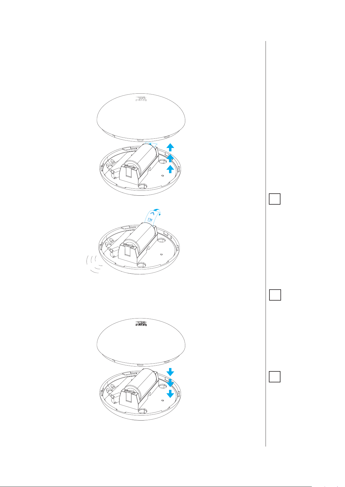
#2: Basic activation
1. Turn the cover counter-clockwise and open it.
5
2. Remove the battery blocker.
!
p
e
e
B
3. Flood Sensor will conrm being powered with a short beep and a
LED blink.
4. Add the device (see “Adding/removing the device” on page 6).
5. Close the cover and turn it clockwise.
NOTE
i
When powered, the
device will indicate
Z-Wave status with
colour of LED:
• Green - the device is
already added to the
Z-Wave network.
• Red - the device is
not added to any
Z-Wave network.
NOTE
i
After completing
installation it is recommended to test
sensor’s operation
by placing the entire
sensor or its probes’
extension wire onto
water surface.
6. Place the sensor on a surface prone to ooding. Three electrodes
underneath the device should evenly touch the surface.
NOTE
i
When changing the
Sensor’s location, it’s
recommended to wake
up the device and recongure the Z-Wave
network by triple clicking the TMP button or
removing and inserting the battery.
BASIC ACTIVATION
Page 6
6
#3: Adding/removing the device
NOTE
i
Adding in security
mode must be performed up to 2 meters
from the controller.
NOTE
i
In case the Sensor is
not added, please reset the Sensor and repeat the adding procedure.
Adding (Inclusion) - Z-Wave device learning mode, allowing to add
the device to existing Z-Wave network.
To add the device to the Z-Wave network:
1. Open the cover.
2. Place the Sensor within the direct range of your Z-Wave controller.
3. Set the main controller in (security/non-security) add mode (see
the controller’s manual).
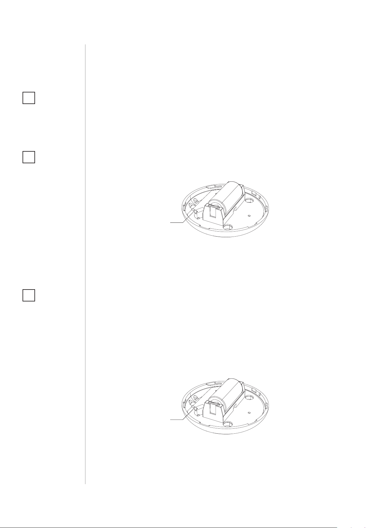
4. Quickly, three times press the TMP button.
TMP
button
5. Wait for the adding process to end.
6. Successful adding will be conrmed by the Z-Wave controller’s
message.
NOTE
i
Removing FloodSensor
from the Z-Wave network restores all the
default parameters of
the device.
Removing (Exclusion) - Z-Wave device learning mode, allowing to
remove the device from existing Z-Wave network.
To remove the device from the Z-Wave network:
1. Open the cover.
2. Place the Sensor within the direct range of your Z-Wave controller.
3. Set the main controller into remove mode (see the controller’s
manual).
4. Quickly, three times press the TMP button.
TMP
button
5. Wait for the removing process to end.
6. Successful removing will be conrmed by the Z-Wave controller’s
message.
ADDING/REMOVING THE DEVICE
Page 7
TMP
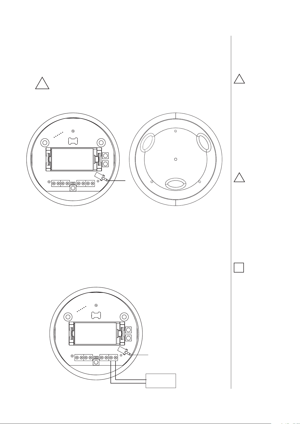
#4: Diagrams and connection
7
Connecting the FIBARO Flood Sensor in a manner
inconsistent with manual may cause risk to health, life or
!
material damage.
Notes for the diagrams and probes marking:
SENS 1
TAM P
SENS 2
ALARM
NC
NC
+ 12
GND
1 2
+12V - 12 / 24 VDC positive terminal
GND - negative (ground) terminal
CAUTION
!
Connect while observing wiring diagram
shown in this manual
only. Incorrect wiring
may be dangerous or
result in the device
breakdown.
Remember to keep
3
the device away from
water or protect holes
for wires from water to
avoid destroying the
device.
CAUTION
!
To prevent accidental
pulling out make certain that cables are
rmly attached to the
wire connectors and
screws are properly
tightened.
ALARM NC - potential-free ood sensor terminals (for wired systems)
TAMP NC - potential-free tamper terminals (for wired systems)
SENS1, SENS2 - ood sensor electrodes’ terminals
TMP - tamper button (used to add/remove the device)
Connection to a constant power source:
SENS 1
TAM P
SENS 2
ALARM
NC
NC
+ 12
GND
TMP
-
12/24 VDC
+
ADAPTER
Make sure to secure
the power cord after
connecting it to the
terminal.
NOTE
i
The TMP button has
two functions:
1. Adding / Removing
the device to / from
the Z-Wave network,
2. Tamper contact
for 4th Association
Group. When a sensor is added to the
Z-Wave network, cover open alarm may be
activated (according
to parameter 74 settings).
DIAGRAMS AND CONNECTION
Page 8

8
NOTE
i
ALARM NC and TAMP
NC connectors may
be used as end-of-line
protective loop’s terminals.
Connection with external wired system:
EXTERNAL
SYSTEM HUB
AUX COM Z1 Z2
SENS 1
TAM P
SENS 2
ALARM
NC
NC
+ 12
GND
TMP
Extending Flood Sensor contacts with a wired probe:
NOTE
i
Mounting screws
shown in a diagram
are not included in
the package. Choose
a screw type depending on the building
material it is being attached to.
NOTE
i
The Sensor detects
electrical conductivity
between electrodes
1 and 3, 1 and 2 and
electrodes connected to contacts (SENS1
and SENS2).
CAUTION
!
Contacts SENS1 and
SENS2 are dedicated to ood detection
only. Do not connect
external voltage!
If you want the device to be mounted on a wall or in a distance from
ooding source, sensor should be extended using an external probe
(not included).
We recommend using extension probes or cables designed to detect
water. Probes ends should be coated with non-corrosive metal.
Connection wires should not be longer than 3m with 18-26AWG
(0.14 - 0.82mm2). It applies also to VDC power source wires.
TAMP
NC
SENS 1
SENS 2
DIAGRAMS AND CONNECTION
Page 9

#5: Powering modes
9
There are two powering modes for the Flood Sensor. By default it is
powered by a factory included battery. In addition it can work with a
constant voltage, after connecting a 12/24V DC power supply to +12
and GND terminals (see „Diagrams and connection” on page 7).
Powering mode conguration is carried out automatically, while the
device is being added into the Z-Wave network.
When battery powered, the Flood Sensor communicates with the
main Z-Wave controller periodically. Detected alarms are sent immediately, but the conguration parameters and associations settings
will only be updated at specied wake up intervals or at manual wake
up (single TMP button click).
When added to the network as a DC powered device, the device will
update its associations and congurations immediately. It will also
allow it to serve as a signal repeater in the Z-Wave network, which
increases the chance of successful communication among devices in
the same network.
Switching to constant voltage powering mode:
1. Remove the sensor from the Z-Wave network.
CAUTION
!
Using batteries other
than specied may
result in explosion.
Dispose of properly,
observing environmental protection
rules.
2. Connect constant voltage power source (12/24 VDC) to +12 and
GND terminals in accordance with „Diagrams and connection” on
page 7.
3. Add the sensor to the Z-Wave network.
The Flood Sensor may operate without a battery if 12/24V power supply is connected. Installing a battery is recommended though, as it
will serve as an emergency power source. When constant power fails,
sensor will automatically shift to backup power mode. All reports, including ood and temperature, will be sent immediately, but it will
not be possible to modify the conguration or association settings
until constant power returns. In this mode Z-Wave signal repeating is
not possible.
FIBARO Flood Sensor’s battery life is estimated at about 2 years at
factory default settings. Current battery level is displayed in a Z-Wave
controller interface. Red battery icon means the battery needs replacement. In order to avoid triggering a tamper alarm while replacing the battery, 4th association group’s associations must be deleted
and conguration parameters should be restored back to default settings.
NOTE
i
The Flood Sensor will
automatically exit
emergency mode
once 12/24 VDC at
+12 and GND terminals is detected
POWERING MODES
Page 10

10
#6: Operating the device
Controlling the Flood Sensor using the TMP button:
The Flood Sensor is equipped with the TMP button, which allows to
perform the following actions:
1x click: send Wake Up notication (in battery mode), conrm selected menu option (if menu is active)
3x click: add/remove the device to/from a Z-Wave network
Holding: enter/navigate through menu
NOTE
i
By default, ood sensor’s insensitivity is
set to 1 second, which
means ooding will
be reported one second after it’s been detected.
Tilt tamper is insensitive to little vibrations
and turns. After its activation, insensitivity
is turned o for 15 seconds. After that, each
Sensor’s movement
will trigger audible
alarm, consisting of 3,
brief acoustic signals.
TMP
button
Controlling the Flood Sensor with FIBARO Home Center controller:
The Flood Sensor has two built-in sensors – ood and temperature
sensors. In the Home Center controller the Sensor will be shown as
two devices.
Visual indications:
The Flood Sensor is equipped with a LED diode, signalling sensor’s
operating modes and alarms. In addition the visual indicator may inform of the Z-Wave network range and the current temperature.
Visual indicator signalling modes:
1. Flood alarm is signalled with alternating white and blue light.
2. In battery powering mode, with parameter no. 63 set to 1, visual
indicator will periodically show temperature readouts (depending on parameter 50, 51, 61 and 62 settings).
3. In constant powering mode, the current temperature readouts
will be continuously signalled with a colour depending on parameter 50, 51, 61 and 62 settings.
4. Currently selected menu position is signalled with an illumination
colour.
OPERATING THE DEVICE
Page 11

Menu allows to perform Z-Wave network actions. In order to use the
menu:
1. Press and hold the TMP button.
2. Wait for the device to indicate desired position with a colour:
• WHITE - conrmation of entering the menu
• GREEN - cancel alarm for associated devices and the control-
ler (only if the device is no longer ooded)
• VIOLET - Z-Wave network’s range test
• YELLOW - full reset
3. Release the TMP button.
4. Click the TMP button to conrm selection.
Waking up the Flood Sensor:
11
When in battery mode the Flood Sensor needs to be woken up to
receive information about the new conguration from the controller,
like parameters and associations.
To wake up the sensor manually, click the TMP button located inside
the housing.
The device will also wake up and update its data upon startup when
added in battery mode.
Resetting the Flood Sensor:
Reset procedure allows to restore the device back to its factory settings, which means all information about the Z-Wave controller and
user conguration will be deleted.
1. Make sure the sensor is powered.
2. Press and hold the TMP button.
3. Wait for the visual LED indicator to glow yellow (4th position of
the MENU).
4. Release the TMP button.
5. Click the TMP button once to conrm selection.
6. After few seconds the device will restart with factory settings,
which is signalled with the red visual indicator colour and
an acoustic signal.
NOTE
i
Resetting the device is
not the recommended way of removing
the device from the
Z-Wave network. Use
reset procedure only
if the primary controller is missing or
inoperable. Certain
device removal can be
achieved by the procedure of removing
described in “Adding/
removing the device”
on page 6.
OPERATING THE DEVICE
Page 12

12
#7: Association
NOTE
i
Association ensures
direct transfer of
control commands
between devices, is
performed without
participation of the
main controller and
requires associated
device to be in the direct range.
Association (linking devices) - direct control of other devices within
the Z-Wave system network e.g. Dimmer, Relay Switch, Roller Shutter
or scene (may be controlled only through a Z-Wave controller).
The Flood Sensor provides the association of four groups:
1st Association Group – “Lifeline” reports the device status and al-
lows for assigning single device only (main controller by default).
2nd Association Group – “Flood Control” devices in this group will
be switched on or o when ood status changes (done via BASIC SET
command frames).
3rd Association Group – “Flood Alarm” is assigned to the device
status - devices in this group will receive notication about ood detection or cancellation. Useful for devices that can trigger alarms.
4th Association Group – “Tamper Alarm” is assigned to the TMP
button and tilt sensor - devices in this group will receive a notication
when the sensor is moved or the cover is taken o (which normally
holds the button). Useful for devices that can trigger alarms. Functionality can be altered by parameter 74.
The Flood Sensor in 2nd to 4th group allows to control
up to 5 regular and 5 multichannel devices per an association group,
with the exception of “LifeLine” that is reserved solely for the controller
and hence only 1 node can be assigned.
It is not recommended to associate more than 10 devices in general,
as the response time to control commands depends on the number
of associated devices. In extreme cases, system response may be delayed.
To add an association (using the FIBARO Home Center controller):
1. Go to device options by clicking the icon:
2. Select the „Advanced” tab.
3. Specify to which group and what devices are to be associated.
4. Wait for the conguration process to end. Sending relevant information to devices added to associated groups may take even a
few minutes.
5. Wake up the device by clicking the TMP button to speed up the
conguration process.
ASSOCIATION
Page 13

#8: Z-Wave range test
13
The Flood Sensor has a built in Z-Wave network main controller’s
range tester.
Follow the below instructions to test the main controller’s range:
1. Press and hold the TMP button until the visual indicator glows
violet.
2. Release the TMP button.
3. Click the TMP button once to conrm selection.
4. Visual indicator will indicate the Z-Wave network’s range (range
signalling modes described below).
5. To exit Z-Wave range test, press the TMP button briey.
Z-Wave range tester signalling modes:
Visual indicator pulsing green - the Flood Sensor attempts to es-
tablish a direct communication with the main controller. If a direct
communication attempt fails, the device will try to establish a routed
communication, through other modules, which will be signalled by
visual indicator pulsing yellow.
Visual indicator glowing green - the Flood Sensor communicates
with the main controller directly.
Visual indicator pulsing yellow - the Flood Sensor tries to establish a routed communication with the main controller through other
modules (repeaters).
CAUTION
!
To make Z-Wave range
test possible, the device must be added
to the Z-Wave controller. Testing may stress
the network, so it is
recommended to perform the test only in
special cases.
NOTE
i
Communication mode
of the Flood Sensor
may switch between
direct and one using
routing, especially if
the device is on the
limit of the direct
range.
Visual indicator glowing yellow - the Flood Sensor communicates
with the main controller through the other modules. After 2 seconds
the device will retry to establish a direct communication with the
main controller, which will be signalled with visual indicator pulsing
green.
Visual indicator pulsing violet - the Flood Sensor does communicate at the maximum distance of the Z-Wave network. If connection
proves successful it will be conrmed with a yellow glow. It’s not recommended to use the device at the range limit.
Visual indicator glowing red - the Flood Sensor is not able to connect to the main controller directly or through another Z-Wave network device (repeater).
ZWAVE RANGE TEST
Page 14

14
#9: Advanced parameters
The Flood Sensor allows to customize its operation to user’s needs.
The settings are available in the FIBARO interface as simple options
that may be chosen by selecting the appropriate box.
In order to congure the Flood Sensor (using the FIBARO Home
Center controller):
1. Go to the device options by clicking the icon:
2. Select the „Advanced” tab.
Wake up interval (battery mode)
Available settings: 0 or 60-86400 (in seconds, 1min - 24h)
Default setting: 21 600 (every 6 hours)
The Flood Sensor will wake up at each dened time interval and always try to connect with the main controller. After successful communication attempt, the sensor will update conguration parameters, associations and settings and then will go into standby mode.
After failed communication attempt (eg. no Z-Wave range) the device
will go into standby mode and retry to establish connection with the
main controller after the next time interval.
Setting wake up interval to 0 disables sending Wake Up notication
to the controller automatically. Wake up may be still performed manually by a single TMP button click.
Longer time interval means less frequent communication and thus a
longer battery life
1. Alarm cancellation delay
Determines time period (in seconds) by which a Flood Sensor will retain the ood state after the ooding itself has ceased. The sensor
will keep on reporting ooding to the main controller. This parameter
setting does not aect acoustic and visual alarms, which turn o immediately after ooding ceases.
ADVANCED PARAMETERS
Available settings: 0-3600 (in seconds, each 1s)
Default setting: 0 Parameter size: 2 [bytes]
2. Acoustic and visual signals On / O in case of ooding
The parameter allows for deactivation visual and acoustic alarm.
Parameter allows for increasing a battery life. Setting changes will not
aect the sensor’s communication with the main controller - commands to association groups, alarms and reports will still be sent.
Page 15

Available settings: 0 - acoustic and visual alarms inactive
1 - acoustic alarm inactive, visual alarm active
2 - acoustic alarm active, visual alarm inactive
3 - acoustic and visual alarms active
Default setting: 3 Parameter size: 1 [byte]
7.
Requested dimming level / roller blind opening level when send-
ing turn on / open command to 2nd association group devices
Determines the requested “on” level to be sent to devices from 2nd
association group upon ood event.
Available settings: 1-99 - requested level
255 - turn a device on
Default setting: 255 Parameter size: 2 [bytes]
9. Deactivate turning o devices in 2nd association group & alarm
cancellation in 3rd group
15
This setting decides whether device turn o commands and alarm
cancellation notications will be sent to devices in 2nd and 3rd association groups (respectively)
Setting the parameter’s value to 0 disables sending these two commands to associated devices. This means that these devices WILL NOT
be informed when the ooding has ceased. It is still possible to cancel
alarms in 3rd association group by choosing second (green) menu
position (see “Menu & visual indications” on page 10).
Available settings: 0 - alarm (ooding) cancellation inactive
1 - alarm (ooding) cancellation active
Default setting: 1 Parameter size: 1 [byte]
10. Temperature measurement interval
Time interval (in seconds) between consecutive measurements of
battery level and temperature (done by built-in temperature sensor).
If the temperature diers from previously reported by a value determined in parameter 12, it will be reported to the Z-Wave controller.
In battery mode more signicant battery level changes will be reported. Short time intervals mean more frequent communication, which
results in shortened battery life.
After consecutive FAILED and SUCCESSFUL communication attempts,
the Sensor will go to standby mode.
Available settings: 1-65535 (in seconds)
Default setting: 300 (5min) Parameter size: 4 [bytes]
12. Temperature measurement hysteresis
Determines a minimum temperature change value (insensitivity level), resulting in a temperature report being sent to the main control-
ADVANCED PARAMETERS
Page 16

16
ler, according to the parameter 10 settings.
Available settings: 1-1000 (each 0.01°C)
Default setting: 50 (0.5°C) Parameter size: 2 [bytes]
50. Low temperature alarm threshold
The parameter stores a temperature value, below which visual indicator blinks with a colour determined by a parameter 61 settings. By
default the visual indicator blinks blue.
Available settings: - 10000 to +10000 (each 0.01°C)
Default setting: 1500 (15°C) Parameter size: 2 [bytes]
51. High temperature alarm threshold
The parameter stores a temperature value, above which visual indicator blinks with a colour determined by the parameter 62 settings. By
default the visual indicator blinks red.
Available settings: - 10000 to +10000 (each 0.01°C)
Default setting: 3500 (35°C) Parameter size: 2 [bytes]
61. Low temperature alarm indicator colour
Parameter stores RGB colour value (see the note below for details).
Available settings: 0-16777215
Default setting: 255 Parameter size: 4 [bytes]
62. High temperature alarm indicator colour
Parameter stores RGB colour value (see the note below for details).
Available settings: 0-16777215
Default setting: 16711680 Parameter size: 4 [bytes]
NOTE
i
The main controller interprets colours as a sum of its component colours value. Each colours value is a number from 0 to 255.
Indicated colour = 65536 * RED + 256 * GREEN + BLUE
Colour Decimal value
Red 16711680
Green 65280
ADVANCED PARAMETERS
Blue 255
Yellow 16776960
Turquoise 65535
Orange 16750848
White 16777215
Indicator turned o 0
Page 17

63. Temperature indication using LED visual indicator
Parameter determines visual indicator’s operation. Setting to 0 turns
the temperature LED indication o, saving battery life.
Available settings: 0 - visual indicator does not indicate the
temperature
1 - visual indicator indicates the temperature
(blink) every Temperature Measurement Interval (parameter 10, constant current and battery) and Wake Up Interval (battery mode)
2 - visual indicator indicates the temperature
continuously, only in constant power mode
Default setting: 2 Parameter size: 1 [byte]
73. Temperature measurement compensation
Parameter stores a temperature value to be added to or deducted
from the current temperature measured by internal temperature sensor in order to compensate the dierence between air temperature
and temperature at the oor level.
17
Available settings: -10 000 to +10 000
Default setting: 0 (0.00°C) Parameter size: 2 [bytes]
74. Alarm frame sent to 1st and 4th Association Group activation
(MOVEMENT_TAMPER / BUTTON_TAMPER)
The device is able to report tamper alarms resulting from sensor’s
tilt/movement or TMP button state change (e.g. taking o the top
cover).
Available settings: 0 - tamper alarms inactive
1 - button tamper alarm active
2 - movement tamper alarm active
3 - button and movement tampers alarm active
Default setting: 2 Parameter size: 1 [byte]
75. Alarms signalization duration
The device is capable of automatically turning o alarm signalization
after a certain amount of time. Long lasting alarm may reduce battery
life, when constantly signalized.
The parameter determines time after which alarm will become “quiet”
- still active but the device will go into battery saving mode. Visual or
acoustic alarm will be reactivated after time specied in the parameter
76. When alarm status ceases, alarm will be turned o immediately.
NOTE
i
Parameter 75 is ignored when parameter 2 is set to 0.
Available settings: 0 - alarms active indenitely
1-65535 - time in seconds
Default setting: 0 Parameter size: 4 [bytes]
ADVANCED PARAMETERS
Page 18

18
NOTE
i
In case a time period
set in parameter 76 is
shorter than the one
specied in parameter
75, the device will not
quiet the alarm, it will
remain active.
76. Alarm signalization reactivation period
Parameter determines a time period after which an alarm will be turned
back on (in case it was turned o by parameter 75 setting). It will also
resend commands to 2nd and 3rd association groups as if the alarm
was detected again.
Available settings: 0 - alarm reactivation inactive
1-65535 - time in seconds
Default setting: 0 Parameter size: 4 [bytes]
77. Flood sensor functionality turned o
Allows to turn o the internal ood sensor. Tamper and built in temperature sensor will remain active.
Available settings: 0 - Default ood sensor operation (ood detec-
tion, reactions)
1 - Built-in ood sensor TURNED OFF (does not
change its state in the main controller, does
not send alarm notications nor turn on/o
commands to 2nd/3rd association groups with
ood state changes. Always visible in the main
controller as turned o)
Default setting: 0 Parameter size: 1 [byte]
78. Associations in Z-Wave network security mode
This parameter denes how commands are sent in specied association groups: as secure or non-secure. Parameter is active only in Z-Wave
network security mode. It does not apply to 1st “Lifeline “group.
Available settings: 0 - none of the groups sent as secure
1 - 2nd group ”Control” sent as secure
2 - 3rd group ”Alarm” sent as secure
4 - 4th group „Tamper” sent as secure
Default setting: 7 Parameter size: 1 [byte]
ADVANCED PARAMETERS
Page 19

#10: Specications
19
Power supply:
Battery type:
Supply type:
Power consumption
(at DC operation):
Maximum voltage at output terminals (ALARM NC,
TAMP NC):
Output terminals maximum current carrying
capacity:
EU standards compliance:
Radio protocol:
Radio frequency:
Range:
Operating temperature:
Measured temperature
range:
Temperature measuring
accuracy:
Dimensions (Diameter x
Height):
Battery and/or power supply unit
3V, CR123A
12–24V DC, LPS or NEC class 2
0.4W
24V DC / 20V AC
25mA
RoHS 2011/65/EU
RED 2014/53/EU
Z-Wave (500 series chip)
868.4 or 869.8 MHz EU;
908.4, 908.42 or 916.0 MHz US;
921.4 or 919.8 MHz ANZ;
869.0 MHz RU;
up to 50m outdoors
up to 40m indoors
(depending on terrain and building
structure)
0–40°C
-20–100°C
0.5°C (within 0–40°C range)
72 x 28 mm
NOTE
i
This product is
intended to be
supplied by a certied
Power Supply Unit
marked “Class 2” or
“LPS” and rated from
12V DC to 24V DC.
CAUTION
!
Using batteries other
than specied may
result in explosion.
Dispose of properly,
observing environmental protection
rules.
NOTE
i
Radio frequency of
individual device
must be same as your
Z-Wave controller.
Check information
on the box or consult
your dealer if you are
not sure.
SPECIFICATIONS
Page 20

20
#11: Regulations
This device complies with Part 15 of the FCC Rules
Operation is subject to the following two conditions:
1. This device may not cause harmful interference
2. This device must accept any interference received, including interference that may cause undesired operation. This equipment has been
tested and found to comply with the limits for a Class B digital device,
pursuant to part 15 of the FCC Rules. These limits are designed to provide reasonable protection against harmful interference in a residential installation. This equipment generates, uses and can radiate radio
frequency energy and, if not installed and used in accordance with the
instructions, may cause harmful interference to radio communications.
However, there is no guarantee that interference will not occur in a particular installation. If this equipment does cause harmful interference
to radio or television reception, which can be determined by turning
the equipment o and on, the user is encouraged to try to correct the
interference by one or more of the following measures:
• Reorient or relocate the receiving antenna.
• Increase the separation between the equipment and receiver.
• Connect the equipment into an outlet on a circuit dierent from
that to which the receiver is connected.
• Consult the dealer or an experienced radio/TV technician for help.
Changes and modications not expressly approved by the manufacturer or registrant of this equipment can void your authority to operate
this equipment under Federal Communications Commission’s rules.
Industry Canada (IC) Compliance Notice
This device complies with Industry Canada license-exempt RSSs. Operation is subject to the following two conditions: (1) this device may
not cause interference, and (2) this device must accept any interference, including interference that may cause undesired operation of the
device.
Cet appareil est conforme aux normes d’exemption de licence RSS d’Industry Canada. Son fonctionnement est soumis aux deux conditions
suivantes : (1) cet appareil ne doit pas causer d’interférence et (2) cet
appareil doit accepter toute interférence, notamment les interférences
qui peuvent aecter son fonctionnement.
Legal Notices
All information, including, but not limited to, information regarding the
features, functionality, and/or other product specication are subject
to change without notice. Fibaro reserves all rights to revise or update its products, software, or documentation without any obligation to
notify any individual or entity.
FIBARO and Fibar Group logo are trademarks of Fibar Group S.A. All
other brands and product names referred to herein are trademarks of
their respective holders.
REGULATIONS
Page 21

DGT Warning Statement
Article 12
Without permission, any company, rm or user shall not alter the frequency, increase the power, or change the characteristics and functions
of the original design of the certied lower power frequency electric
machinery.
Article 14
The application of low power frequency electric machineries shall not
aect the navigation safety nor interfere a legal communication, if an
interference is found, the service will be suspended until improvement
is made and the interference no longer exists.
第十二條
經型式認證合格之低功率射頻電機,非經許可,公司、商號或使用
者均不得擅自變更頻率、加大功率或變更原設計之特性及功能。
第十四條
低功率射頻電機之使用不得影響飛航安全及干擾合法通信;經發現
有干擾現象時,應立即停用,並改善至無干擾時方得繼續使用。
前項合法通信,指依電信法規定作業之無線電通信。
低功率射頻電機須忍受合法通信或工業、科學及醫療用電波輻射性
電機設備之干擾。
21
Warning
This product is not a toy. Keep away from children and animals!
Information according REACH
The included Panasonic CR123A battery contains 1,2-Dimethoxyethane substance. Normal use of the device does not expose the user to
a given substance.
Declaration of conformity
Hereby, Fibar Group S.A. declares that the device is in compliance with
the essential requirements and other relevant provisions of Directive
2014/53/EU. The full text of the EU declaration of conformity is available
at the following internet address: www.manuals.baro.com
WEEE Directive Compliance
Device labelled with this symbol should not be disposed with other
household wastes. It shall be handed over to the applicable collection
point for the recycling of waste electrical and electronic equipment.
REGULATIONS
 Loading...