

Page 1
OPERATING
MANUAL
EN
FIBARO DOOR/WINDOW SENSOR 2
FGDW-002
CONTENTS
#1: Description and features 3
#2: Basic activation 4
#3: Adding/removing the device 5
#4: Physical installation 6
#5: Operating the device 7
v1.1
#6: Association 9
#7: Advanced parameters 10
#8: Specications 14
#9: Regulations 15
Page 2

2
Important safety information
Read this manual before attempting to install the device!
!
Failure to observe recommendations included in this manual
may be dangerous or cause a violation of the law. The manufacturer,
Fibar Group S.A. will not be held responsible for any loss or damage
resulting from not following the instructions of operating manual.
The alarm functionality of devices is an additional feature increasing
the comfort level of your home automation system. If you want to
use professional security service, please contact them to determine
what systems can provide a protection of your estate.
Compliance with safety standards:
The device is designed to be used in Z-wave home automation systems (e.g. FIBARO) and is complaint with IEC/UL/CSA 60950-1. In case
of the integration with another system, e.g. alarm system, it is required to verify the compliance with additional standards.
General information about
the FIBARO System
FIBARO is a wireless smart home automation system, based on the
Z-Wave protocol. All of available devices can be controlled through
a computer (PC or Mac), smartphone or tablet. Z-Wave devices are
not only receivers, but can also repeat the signal, increasing the
Z-Wave network’s range. It gives advantage over traditional wireless
systems that require direct link between transmitter and receiver, as
a result the construction of the building could aect network’s range
negatively.
Every Z-Wave network has its unique identication number (home
ID). Multiple independent networks can exist in the building without
interfering. Transmission security of FIBARO System is comparable to
wired systems.
Z-Wave technology is the leading solution in smart home automation.
There is a wide range of Z-Wave devices that are mutually
compatible, independently of manufacturer. It gives the system the
ability to evolve and expand over time. For more information visit
www.baro.com.
Page 3
#1: Description and features
FIBARO Door/Window Sensor 2 is a wireless, battery powered Hall
eect contact sensor, compatible with the Z-Wave Plus standard.
Changing the device’s status will automatically send signal to the
Z-Wave controller and associated devices.
Sensor can be used to trigger scenes and wherever there is a need
for information about opening or closing of doors, windows, garage
doors, etc. Opening is detected by separating the sensor’s body and
the magnet.
In addition the FIBARO Door/Window Sensor 2 is equipped with
a built-in temperature sensor.
3
Main features of FIBARO Door/Window Sensor 2:
• Compatible with any Z-Wave or Z-Wave+ Controller,
• Supports protected mode (Z-Wave network Security Mode) with
AES-128 encryption,
• Door/window opening detected through separation of Sensor’s
body and a magnet,
• Built-in temperature sensor,
• Detects tampering, when detached or opened,
• Easily mounted on doors, windows, garage gates and roller blinds,
• Battery powered,
• Visual LED indicator signalling status of the device,
• 7 color variations.
FIBARO Door/Window Sensor 2
is a fully compatible Z-Wave
PLUS device.
NOTE
i
This device may be
used with all devices
certied with Z-Wave
Plus certicate and
should be compatible
with such devices produced by other manufacturers.
NOTE
i
Z-Wave Controller
must support Z-Wave
Security Mode in
order to fully utilize the
product.
DESCRIPTION AND FEATURES
Page 4
4
#2: Basic activation
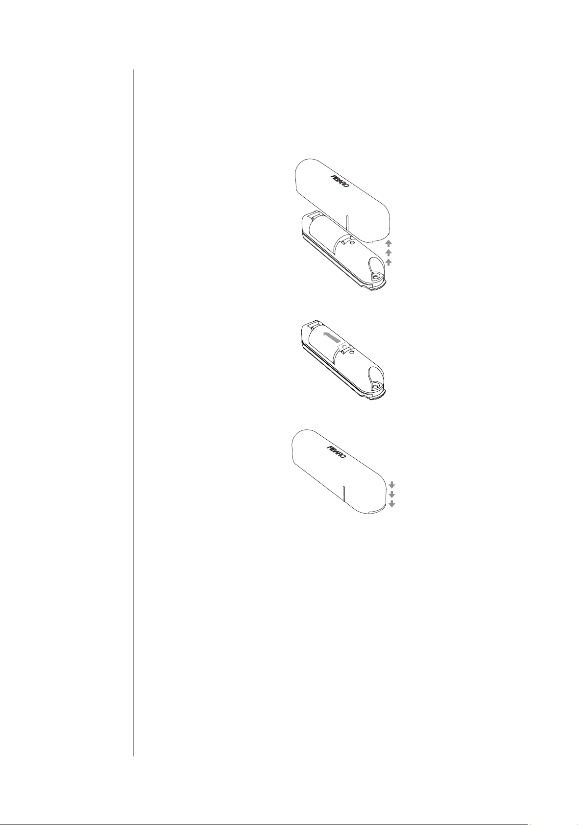
1. Take o the cover.
2. Remove the battery blocker.
3. Close the cover.
4. Add the device (see “Adding/removing the device” on page 5).
5. Install the device (see “Physical installation” on page 6).
BASIC ACTIVATION
Page 5
#3: Adding/removing the device
5
Adding (Inclusion) - Z-Wave device learning mode, allowing to add
the device to existing Z-Wave network.
To add the device to the Z-Wave network:
1. Place the Door/Window Sensor 2 within the direct range of your
Z-Wave controller.
2. Set the main controller in (Security/non-Security Mode) add mode
(see the controller’s manual).
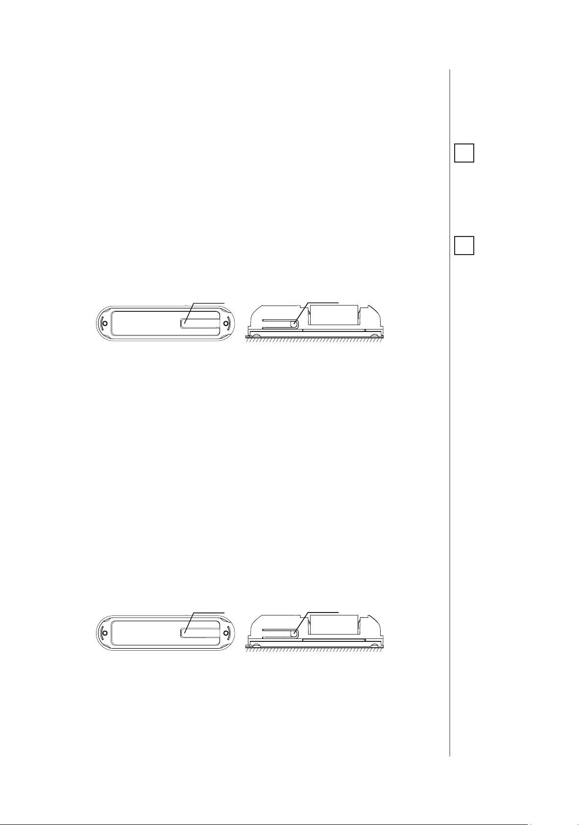
3. Quickly, three times press one of the TMP buttons (while the other
button is pressed).
TMP
button
With cover closed
TMP
button
When attached to a surface
4. Wait for the adding process to end.
5. Successful adding will be conrmed by the Z-Wave controller’s
message.
NOTE
i
Adding in Security
Mode must be performed up to 2 meters
from the controller.
NOTE
i
In case of problems
with adding the device, please reset the
device and repeat the
adding procedure.
Removing (Exclusion) - Z-Wave device learning mode, allowing to
remove the device from existing Z-Wave network.
To remove the device from the Z-Wave network:
1. Place the Door/Window Sensor 2 within the direct range of your
Z-Wave controller.
2. Set the main controller into remove mode (see the controller’s
manual).
3. Quickly, three times press one of the TMP buttons (while the other
button is pressed).
TMP
button
With cover closed
TMP
button
When attached to a surface
4. Wait for the removing process to end.
5. Successful removing will be conrmed by the Z-Wave controller’s
message.
ADDING/REMOVING THE DEVICE
Page 6

6
#4: Physical installation
NOTE
i
It is possible to install the device with
screws (not included).
We recommend using
2.5mm x 16mm countersunk head screws
with 5mm head diameter. The magnet still
has to be stuck on.
To install the Door/Window Sensor:
1. Peel o the protective layer from the sticker on the device.
2. Stick the device onto the door/window frame.
3. Peel o the protective layer from the sticker on the magnet.
4. Stick the magnet onto the moving part of the door/window, no
further than 5mm from the sensor.
Positioning of the Sensor and the magnet:
Correct positioning of the magnet in relation to the Sensor:
(vertical line marks should align)
max. 5 mm
PHYSICAL INSTALLATION
Page 7

#5: Operating the device
Tamper (TMP) button:
The Door/Window Sensor 2 is equipped with a tamper switch with
two buttons.
First TMP button is located inside the device, pressed by the closed
cover and is used to detect openning it.
Second TMP button is located at bottom of the device, pressed by the
surface on which the device is mounted and is used to detect detaching the device.
For the tamper switch to work one of the buttons must always be
pressed!
When one of the buttons is released, the tamper alarm will be send to
the controller and associated devices.
7
Additionally, tamper button allows to control the device directly.
TMP
button
With cover closed
TMP
button
When attached to a surface
Controlling the Door/Window Sensor 2 with FIBARO Home Center
controller:
After adding the Sensor to the FIBARO System, it will be represented
by two or three icons in Home Center interface.
First icon informs about the status of magnetic sensor (open/close),
second icon displays temperature measured by the built-in sensor.
Third icon is assigned to high/low temperature alarm and is visible only
if parameter 54 is not equal to 0.
Waking up the Door/Window Sensor 2:
The Door/Window Sensor 2 needs to be woken up to receive information about the new conguration from the controller, like parameters
and associations.
To wake up the sensor manually, click one of the TMP buttons (while
the other button is pressed).
OPERATING THE DEVICE
Page 8

8
NOTE
i
Opening the casing
may result in triggering an alarm. To avoid
it, remove the associations for the 3rd
group.
NOTE
i
Resetting the device is
not the recommended way of removing
the device from the
Z-Wave network. Use
reset procedure only
if the primary controller is missing or
inoperable. Certain
device removal can be
achieved by the procedure of removing
described in “Adding/
removing the device”
on page 5.
Resetting the Door/Window Sensor 2:
Reset procedure allows to restore the device back to its factory settings, which means all information about the Z-Wave controller and
user conguration will be deleted.
In order to reset the device:
1. Open the cover.
2. Remove the battery.
3. Install the battery while holding both TMP buttons.
4. Visual LED indicator will be ashing slowly for 5 seconds - keep
holding the buttons.
5. Release one button when the LED indicator starts ashing quickly.
6. Click released button once to conrm launching of reset procedure.
7. Wait a few seconds until a long blink of the LED indicator. Do not
remove the battery.
8. Visual LED indicator will blink 5 times quickly to conrm the reset.
Replacing the battery:
In FIBARO Home Center controller current battery level is displayed
in the interface. If a battery icon turns red, it means the battery needs
replacement.
NOTE
i
Command Class Basic value is related to
the status of contact
sensor (0x00 - closed,
0xFF - opened, on default setting of parameter 1. “Door/window
state “).
Notication report:
The device uses Notication Command Class to report dierent
events.
Notication Type Event
Home Security
Tampering, product covering
removed
Access Control Door/window opened
Access Control Door/window closed
Power Management Replace battery now
Heat Alarm
Heat Alarm
Overheat detected, unknown
location
Underheat detected, unknown
location
OPERATING THE DEVICE
Page 9

#6: Association
9
Association (linking devices) - direct control of other devices within
the Z-Wave system network e.g. Dimmer, Relay Switch, Roller Shutter
or scene (may be controlled only through a Z-Wave controller).
The Door/Window Sensor 2 provides the association of three
groups:
1st Association Group – “Lifeline” reports the device status and al-
lows for assigning single device only (main controller by default).
2nd Association Group – “On/O” is assigned to the device status contact sensor (sends Basic Set command frames).
3rd Association Group – “Tamper” is assigned to the TMP switch
(sends alarm command frames).
The Door/Window Sensor 2 in 2nd and 3rd group allows to control
5 devices (regular or multichannel) per an association group.
“LifeLine” group is reserved solely for the controller and hence only 1
node can be assigned.
NOTE
i
Association allows
transfer of control
commands between
devices without participation of the main
controller.
Direct range between
devices is recommended.
NOTE
i
“Lifeline“ supported
Z-Wave Command
Classes: Notication,
Battery, Sensor Multilevel, Device Reset
Locally.
To add an association (using the Home Center controller):
1. Go to device options by clicking the icon:
2. Select the „Advanced” tab.
3. Specify to which group and what devices are to be associated.
4. Save the changes.
5. Wake up the device manually or wait for the next automatic wake
up.
ASSOCIATION
Page 10

10
#7: Advanced parameters
NOTE
i
Entering invalid value
of parameter will result in response with
Application Rejected
frame and not setting
the value.
The Door/Window Sensor 2 allows to customize its operation to user’s
needs. Settings are available in the FIBARO interface as simple options that may be chosen by selecting the appropriate box.
In order to congure the Door/Window Sensor 2 (using
the Home Center controller):
1. Go to the device options by clicking the icon:
2. Select the „Advanced” tab.
Wake up interval
Available settings: 0 or 3600-64800 (in seconds (1-18h), 3600s (1h)
step)
Default setting: 21600 (6h)
The Door/Window Sensor will wake up after each dened time interval and always try to connect with the main controller. After a successful communication attempt, the sensor will update conguration
parameters, associations and settings and will go into standby mode.
After failed communication attempt (e.g. lack of Z-Wave range) the
device will go into standby mode and retry to establish connection
with the main controller after the next time interval.
NOTE
i
Parameter 2 values
may be combined, e.g.
1+2=3 means that indications for opening/
closing and waking up
are enabled.
Setting wake up interval to 0 disables sending Wake Up Notication
frame automatically. Wake up may be still performed manually by a
clicking one of the TMP buttons (while the other button is pressed).
Longer time interval means less frequent communication and thus a
longer battery life.
1. Door/window state
This parameter allows to set in what state is door/window when the
magnet is close to the sensor.
Available settings: 0 - closed when magnet near
1 - opened when magnet near
Default setting: 0 Parameter size: 1 [byte]
2. Visual LED indications
This parameter denes events indicated by the visual LED indicator.
Disabling events might extend battery life.
Available settings: 1 - indication of opening/closing status change
2 - indication of wake up (1 x click or periodical)
4 - indication of device tampering
Default setting: 6 Parameter size: 1 [byte]
ADVANCED PARAMETERS
Page 11

3. Associations in Z-Wave network Security Mode
This parameter denes how commands are sent in specied association groups: as secure or non-secure. Parameter is active only in Z-Wave
network Security Mode. It does not apply to 1st group “Lifeline”.
Available settings: 0 - none of the groups sent as secure
1 - 2nd group ”On/O” sent as secure
2 - 3rd group ”Tamper” sent as secure
3 - 2nd and 3rd group sent as secure
Default setting: 3 (all) Parameter size: 1 [byte]
11. 2nd association group triggers
Parameter denes events which result in sending on/o commands
to devices added to the 2nd association group.
These commands are sent alternately to switch the devices on and o.
Available settings: 0 - switch after opening and closing
11
1 - switch after opening (parameter 12)
2 - switch after closing (parameter 13)
Default setting: 0 Parameter size: 1 [byte]
12. Association for opening - value sent
Value sent to devices in 2nd association group when opening is
detected
The value of 0 turns OFF the device, 255 turns it ON.
In case of associating devices allowing smooth control, values 1-99
allow to set an associated device to a specied level.
Available settings: 0-99 or 255
Default setting: 255 Parameter size: 2 [bytes]
13. Association for closing - value sent
Value sent to devices in 2nd association group when closing is
detected
The value of 0 turns OFF the device, 255 turns it ON.
In case of associating devices allowing smooth control, values 1-99
allow to set an associated device to a specied level.
Available settings: 0-99 or 255
Default setting: 0 Parameter size: 2 [bytes]
14. Association for opening - time delay
Time that must elapse from opening to send the command frame to
to devices in 2nd association group.
Available settings: 0-32400 - time in seconds
Default setting: 0 Parameter size: 2 [bytes]
ADVANCED PARAMETERS
Page 12

12
15. Association for closing - time delay
Time that must elapse from closing to send the command frame to
devices in 2nd association group.
Available settings: 0-32400 - time in seconds
Default setting: 0 Parameter size: 2 [bytes]
30. Tamper - alarm cancellation delay
Time period after which a tamper alarm will be cancelled.
Available settings: 0-32400 - time in seconds
Default setting: 5 Parameter size: 2 [bytes]
31. Tamper - reporting alarm cancellation
Reporting cancellation of tamper alarm to the controller and 3rd association group.
Available settings: 0 - do not send tamper cancellation report
NOTE
i
Parameter 51 is active
only if parameter 50 is
not set to 0.
NOTE
i
Temperature measurement is performed
before sending any
report (regardless of
parameter no. 50). Excessive reporting can
aect battery lifetime.
Reporting on the basis of temperature
change (parameter
no. 51) is recommended.
1 - send tamper cancellation report
Default setting: 1 Parameter size: 1 [byte]
50. Interval of temperature measurements
This parameter denes how often the temperature will be measured.
The shorter the time, the more frequently the temperature will be
measured, but the battery life will shorten.
Available settings: 0 - temperature measurements disabled
5-32400 - time in seconds
Default setting: 300 (5min) Parameter size: 2 [bytes]
51. Temperature reports threshold
This parameter denes the change of temperature in comparison
with last reported, resulting in temperature report being sent to the
main controller.
Available settings: 0 - temperature reports based on threshold
disabled
1-300 - temperature threshold (0.1-30°C, 0.1°C
step)
Default setting: 10 (1
°C )
Parameter size: 2 [bytes]
52. Interval of temperature reports
This parameter determines how often the temperature reports will be
sent to the main controller (regardless of parameters 50 and 51).
Available settings: 0 - periodic temperature reports disabled
300-32400 - time in seconds
ADVANCED PARAMETERS
Default setting: 0 Parameter size: 2 [bytes]
Page 13

53. Temperature oset
The value to be added to the actual temperature, measured by the sensor (temperature compensation).
Available settings: -1000–1000 (-100–100°C, 0.1°C step)
Default setting: 0 (0
°C )
Parameter size: 2 [bytes]
54. Temperature alarm reports
Temperature alarms reported to the Z-Wave controller. Thresholds are
set in parameters 55 and 56.
Available settings: 0 - temperature alarms disabled
1 - high temperature alarm
2 - low temperature alarm
3 - high and low temperature alarms enabled
Default setting: 0 Parameter size: 1 [byte]
55. High temperature alarm threshold
13
If temperature is higher than set value, overheat notication will be
sent and high temperature alarm will be triggered (if activated).
Available settings: 1-600 (0.1-60°C, 0.1°C step)
Default setting: 350 (35°) Parameter size: 2 [bytes]
56. Low temperature alarm threshold
If temperature is lower than the set value, underheat notication will
be sent and low temperature alarm will be triggered (if activated).
Available settings: 0-599 (0-59.9°C, 0.1°C step)
Default setting: 100 (10°) Parameter size: 2 [bytes]
NOTE
i
Value set in parameter 55 must be higher
than value set in parameter 56.
ADVANCED PARAMETERS
Page 14

14
#8: Specications
CAUTION
!
Using batteries other
than specied may
result in explosion.
Dispose of properly,
observing environmental protection
rules.
NOTE
i
Battery life depends
on frequency of usage, number of associations/scenes, Z-Wave
routing and network
load.
NOTE
i
Radio frequency of
individual device
must be same as your
Z-Wave controller.
Check information
on the box or consult
your dealer if you are
not sure.
Power supply:
Battery type:
Battery life:
EU directives compliance:
Radio protocol:
Radio frequency:
Range:
Destined environment:
Operating temperature:
Temperature measuring
range:
Temperature measuring
accuracy:
Dimensions (L x W x H):
3.6V DC battery
ER14250 ½ AA
est. 2 years (default settings)
RoHS 2011/65/EU
RED 2014/53/EU
Z-Wave (500 series chip)
868.4 or 869.8 MHz EU;
908.4, 908.42 or 916.0 MHz US;
921.4 or 919.8 MHz ANZ;
869.0 MHz RU;
up to 50m (164ft) outdoors
up to 40m (131ft) indoors
(depending on terrain and building
structure)
Indoor use only
0-40°C (32-104°F)
0-60°C (32-140°F)
±0.5°C (±0.9°F)
71 x 18 x 18 mm
(2.8 x 0.7 x 0.7 inch)
SPECIFICATIONS
Page 15

#9: Regulations
This device complies with Part 15 of the FCC Rules
Operation is subject to the following two conditions:
1. This device may not cause harmful interference
2. This device must accept any interference received, including interfe-
rence that may cause undesired operation. This equipment has been
tested and found to comply with the limits for a Class B digital device,
pursuant to part 15 of the FCC Rules. These limits are designed to provide reasonable protection against harmful interference in a residential installation. This equipment generates, uses and can radiate radio
frequency energy and, if not installed and used in accordance with the
instructions, may cause harmful interference to radio communications.
However, there is no guarantee that interference will not occur in a particular installation. If this equipment does cause harmful interference
to radio or television reception, which can be determined by turning
the equipment o and on, the user is encouraged to try to correct the
interference by one or more of the following measures:
• Reorient or relocate the receiving antenna.
• Increase the separation between the equipment and receiver.
• Connect the equipment into an outlet on a circuit dierent from
that to which the receiver is connected.
• Consult the dealer or an experienced radio/TV technician for help.
15
Changes and modications not expressly approved by the manufacturer or registrant of this equipment can void your authority to operate
this equipment under Federal Communications Commission’s rules.
Industry Canada (IC) Compliance Notice
This device complies with Industry Canada license-exempt RSSs. Operation is subject to the following two conditions: (1) this device may
not cause interference, and (2) this device must accept any interference, including interference that may cause undesired operation of the
device.
Cet appareil est conforme aux normes d’exemption de licence RSS d’Industry Canada. Son fonctionnement est soumis aux deux conditions
suivantes : (1) cet appareil ne doit pas causer d’interférence et (2) cet
appareil doit accepter toute interférence, notamment les interférences
qui peuvent aecter son fonctionnement.
Legal Notices
All information, including, but not limited to, information regarding the
features, functionality, and/or other product specication are subject
to change without notice. Fibaro reserves all rights to revise or update its products, software, or documentation without any obligation to
notify any individual or entity.
FIBARO and Fibar Group logo are trademarks of Fibar Group S.A. All
other brands and product names referred to herein are trademarks of
their respective holders.
REGULATIONS
Page 16

16
DGT Warning Statement
Article 12
Without permission, any company, rm or user shall not alter the frequency, increase the power, or change the characteristics and functions
of the original design of the certied lower power frequency electric
machinery.
Article 14
The application of low power frequency electric machineries shall not
aect the navigation safety nor interfere a legal communication, if an
interference is found, the service will be suspended until improvement
is made and the interference no longer exists.
第十二條
經型式認證合格之低功率射頻電機,非經許可,公司、商號或使用
者均不得擅自變更頻率、加大功率或變更原設計之特性及功能。
第十四條
低功率射頻電機之使用不得影響飛航安全及干擾合法通信;經發現
有干擾現象時,應立即停用,並改善至無干擾時方得繼續使用。
前項合法通信,指依電信法規定作業之無線電通信。
低功率射頻電機須忍受合法通信或工業、科學及醫療用電波輻射性
電機設備之干擾。
Warning
This product is not a toy. Keep away from children and animals!
Declaration of conformity
Hereby, Fibar Group S.A. declares that the device is in compliance with
the essential requirements and other relevant provisions of Directive
2014/53/EU. The full text of the EU declaration of conformity is available
at the following internet address: www.manuals.baro.com
WEEE Directive Compliance
Device labelled with this symbol should not be disposed with other
household wastes. It shall be handed over to the applicable collection
point for the recycling of waste electrical and electronic equipment.
REGULATIONS
 Loading...