

Page 1
OPERATING
MANUAL
4 x BEEP
)
)
RED LED
)
BLINKING
MOVE TO
FRESH AIR!
EN
&
FIBARO CO SENSOR
FGCD-001
CONTENTS
#1: Description and features 3
#2: Basic activation 4
#3: Adding/removing the device 5
#4: Physical installation 6
#5: Operating the device 7
#6: Visual indications & acoustic signals 8
v1.1
#7: Battery 9
#8: Associations 10
#9: Advanced parameters 12
#10: Specications 16
#11: Regulations 17
Page 2

2
Important safety information
Read this manual before attempting to install the device!
Failure to observe recommendations included in this manual may be
dangerous or cause a violation of the law. The manufacturer, Fibar Group
S.A. will not be held responsible for any loss or damage resulting from
not following the instructions of operating manual.
General carbon monoxide information
Carbon monoxide (CO) is a colourless, odourless, and tasteless poison
gas that can be fatal when inhaled. It is produced when liquid, solid, or
gas fuel is burned.
Symptoms of carbon monoxide poisoning
The early symptoms of carbon monoxide poisoning can be confused
with u-like symptoms: headache, dizziness and nausea. Breathing carbon monoxide causes these symptoms even in healthy people. It can
also cause sleepiness, vision problems (including blurred vision), ringing in the ears, aching arms and legs, irregular breathing, fatigue and
confusion. At very high levels, it causes loss of consciousness and death.
Some external factors, eg. exposure to high concentration of basic
(non-acidic) gases, silicone vapors, hydrogen sulde or sulfuric acid gas,
organic vapors, contact with water, dust and oil mist, or dew condensation may aect the reliability of the device operation.
This device may not protect from long-term exposure to low levels of
carbon monoxide which can also lead to neurological symptoms.
The device is not a substitute for appropriate ventilation and exhaust
systems.
General information about
the FIBARO System
FIBARO is a wireless smart home automation system, based on the
Z-Wave protocol. All of available devices can be controlled through
a computer (PC or Mac), smartphone or tablet. Z-Wave devices (nonbattery powered) are not only receivers, but can also repeat the
signal, increasing the Z-Wave network’s range. It gives advantage
over traditional wireless systems that require direct link between
transmitter and receiver, as a result the construction of the building
could aect network’s range negatively.
Every FIBARO network has its unique identication number (home
ID). Multiple independent networks can exist in the building without
interfering. Transmission security of FIBARO System is comparable to
wired systems.
Z-Wave technology is the leading solution in smart home automation.
There is a wide range of Z-Wave devices that are mutually
compatible, independently of manufacturer. It gives the system the
ability to evolve and expand over time. For more information visit:
www.baro.com.
Page 3
#1: Description and features
FIBARO CO Sensor is an ultra-light, compact, battery-powered
carbon monoxide detector, designed to be placed on a wall.
Its high sensitivity allows to detect the presence of the carbon
monoxide (CO) gas at the early stage in order to prevent carbon
monoxide poisoning.
Alarm is signalled with a built-in siren, blinking LED indicator and by
sending commands to Z-Wave network devices.
Additionally, the device is equipped with a temperature sensor.
3
Main features of FIBARO CO Sensor:
• compatible with any Z-Wave or Z-Wave+ Controller
• supports protected mode (Z-Wave network security mode) with
AES-128 encryption
• wall-mounted
• battery-powered
• completely wireless
• alarm signalled with a built-in siren and LED diode
• built-in temperature sensor
FIBARO CO Sensor is a fully
compatible Z-Wave PLUS device.
NOTE
i
This device may be
used with all devices certied with
the Z-Wave Plus certicate and should be
compatible with such
devices produced by
other manufacturers.
NOTE
i
FIBARO CO Sensor is a
Security Enabled
Z-Wave Plus product
and a Security Enabled Z-Wave Controller must be used in order to fully utilize the
product.
DESCRIPTION AND FEATURES
Page 4
4
NOTE
i
Recommended height
of installation is dependant on the purpose of the room and
height at which head
typically is.
NOTE
i
FIBARO CO Sensor
may operate as a
stand-alone carbon
monoxide detector or
may be used in cooperation with Z-Wave
Controller (eg. FIBARO
Home Center) as a part
of smart home system.
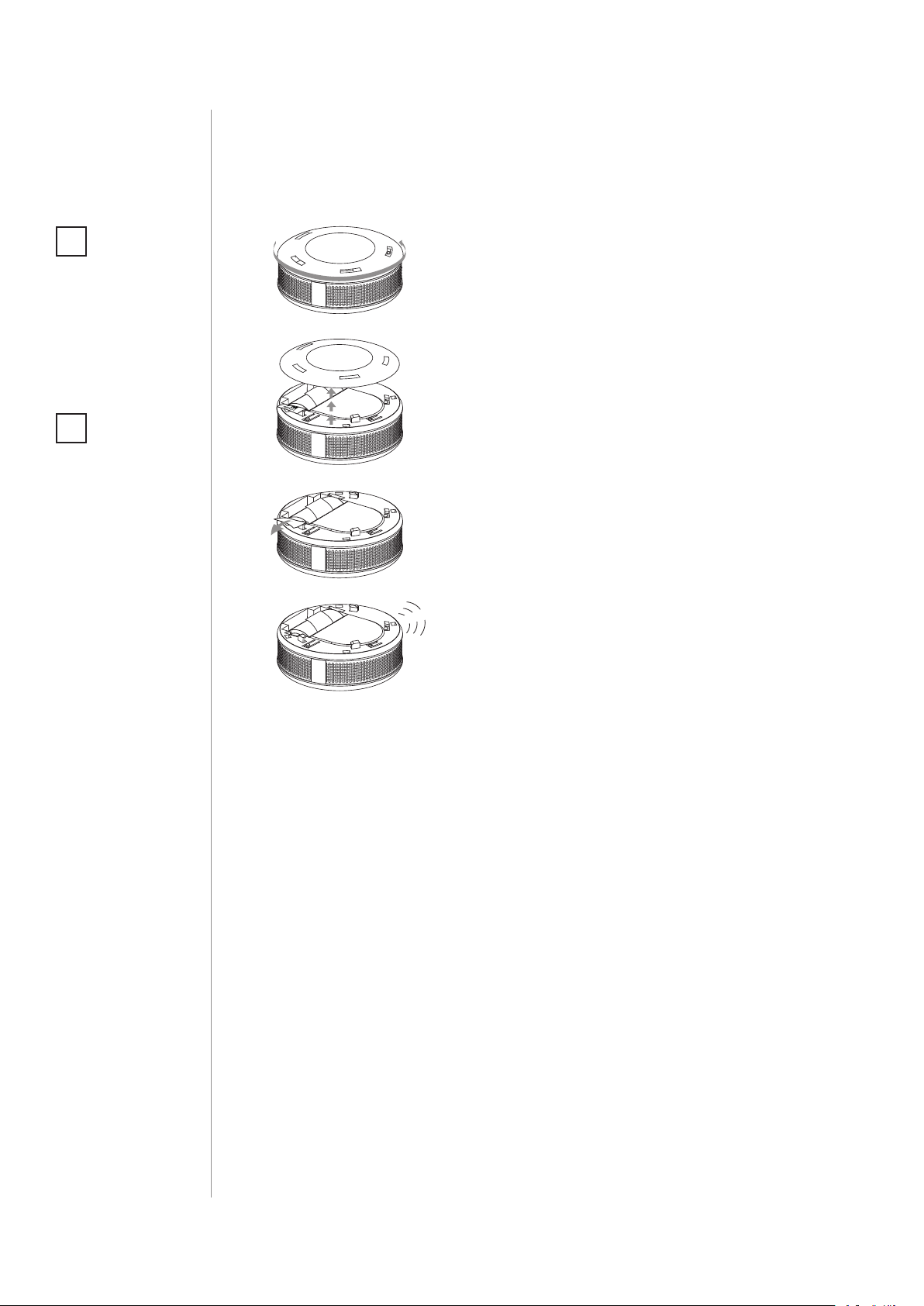
#2: Basic activation
1. Turn the cover counter-clockwise.
PULL
1xCR123A(3V)
PULL
1xCR123A(3V)
e
PULL
1xCR123A(3V)
B
2. Take o the cover.
3. Remove the paper strip protecting
the battery.
!
p
e
4. Proper powering up will be conrmed with a short beep.
5. Add the device (as described in "Adding/removing the device") if you
want to use it in the Z-Wave network.
BASIC ACTIVATION
Page 5
#3: Adding/removing the device
5
Adding (Inclusion) - Z-Wave device learning mode, allowing to add
the device to existing Z-Wave network.
To add the device:
1. Place the device within direct range of the Z-Wave controller.
2. Set the main Z-Wave controller in (security/non-security) adding
mode (see the controller’s manual).
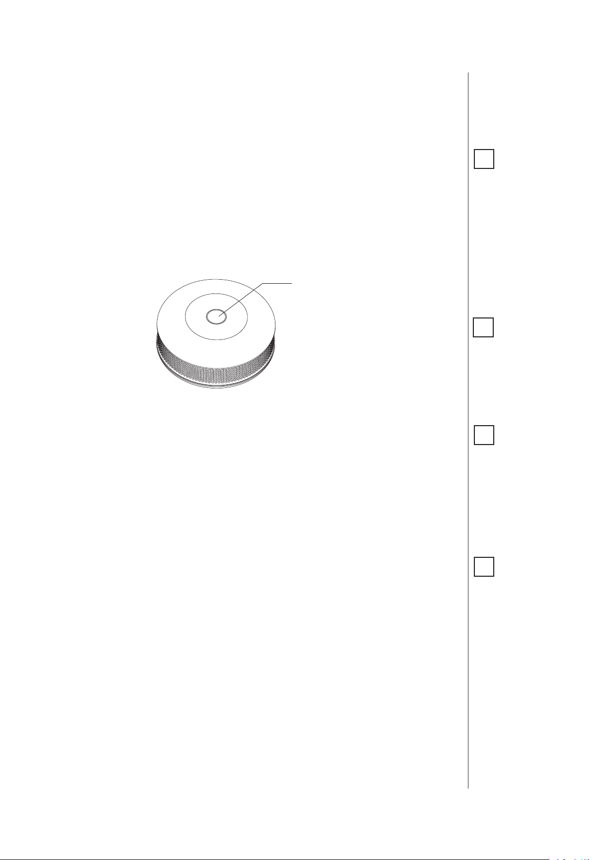
3. Quickly, triple click the button located on the casing.
Button
4. Wait for the device to be added into the system.
5. Successful adding will be conrmed by the Z-Wave controller’s
message.
Removing (Exclusion) - Z-Wave device learning mode, allowing to
remove the device from existing Z-Wave network.
NOTE
i
When powered, the
device will indicate
Z-Wave status with
colour of LED:
• Green - the device is
already added to the
Z-Wave network.
• Red - the device is
not added to any
Z-Wave network.
NOTE
i
In case the device is
not added, please reset the device and repeat the adding procedure.
NOTE
i
When changing the
Sensor’s location, it’s
recommended to wake
up the device and recongure the Z-Wave
network by clicking
the button.
To remove the device:
1. Place the device within direct range of the Z-Wave controller.
2. Set the main Z-Wave controller in remove mode (see the
controller’s manual).
3. Quickly, triple click the button located on the casing.
4. Wait for the removing process to end.
5. Successful removing will be conrmed by the Z-Wave controller’s
message.
ADDING/REMOVING THE DEVICE
NOTE
i
Removing the device
from the Z-Wave network restores all the
default parameters of
the device.
Page 6
6
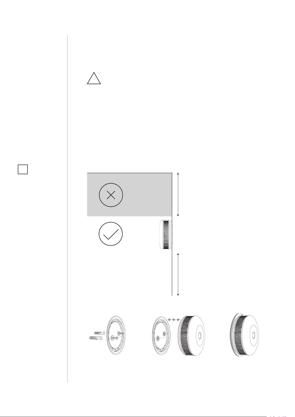
#4: Physical installation
READ BEFORE INSTALLATION
!
AND HEED ALL THE WARNINGS!
• The device should be installed below the ceiling level.
• The device should be installed on the wall, at least 30 cm (1 ft) away
from the corners.
• The device should not be installed: in a bathroom, next to heat
sources, within range of kids, obstructed from possible carbon
monoxide sources, in direct sunlight.
• The device should be installed by a qualied installator.
• Do not paint the device.
• The device should be cleaned with a slightly damp cloth or moistened tissue.
NOTE
i
Recommended height
of installation is dependant on the purpose of the room and
height at which head
typically is.
Place of installation:
NOT HERE
HERE
Installation on the wall:
CEILING
30cm/1ft
WALL
1.5m/5ft
FLOOR
PHYSICAL INSTALLATION
1.
1. Mount the cover on a wall.
2. Attach the device to its cover.
3. Turn the device clockwise to close it.
2.
3.
Page 7

#5: Operating the device
Menu allows to perform Z-Wave network actions. In order to use the
menu:
1. Press and hold the button for 3 seconds
2. You should hear a short signal while the LED diode blinks white.
3. Release the button.
7
4. Wait for the device to indicate desired menu position with a colour:
• White - conrm the start of the rmware update process
• Green - send the current state of CO Alarm
• Magenta - Z-Wave network's range test
• Yellow - the device reset
5. Press the button to conrm selection.
Waking up the device:
The CO Sensor needs to be woken up to receive information about
the new conguration from the Z-Wave controller, like parameters
and associations. To wake up the sensor manually click the button
located on the casing.
Self-test:
1. Press and hold the button.
2. The LED indicator will glow white and you will hear a short beep.
3. Release the button when you hear the rst alarm sequence.
NOTE
i
CO Sensor must be detached from the wall
and battery level must
be greater than 30%
of its full capacity to
perform the rmware
update process.
CAUTION
!
The alarm is very loud!
Only the rst alarm sequence is quieter.
4. Move away from the device to protect your hearing.
If the self-test procedure does not result in emitting sound
!
and red light signal, replace the device.
Resetting the device to factory defaults:
Reset procedure allows to restore the device back to its factory settings, which means all information about the Z-Wave controller and
user conguration will be deleted.
1. Press and hold the button.
2. Release the button when LED indicator glows white and short
beep sounds.
3. Click the button when LED indicator glows yellow.
4. After few seconds the device will be reset (conrmed by red LED
indicator and long beep).
NOTE
i
Resetting the device is
not the recommended
way of removing the
device from the Z-Wave
network. Use the reset
procedure only if the
primary controller is
missing or inoperable.
Certain device removal
can be achieved by the
procedure of removing
described in "Adding/
removing the device"
on page 5.
OPERATING THE DEVICE
Page 8

8
#6: Visual indications & acoustic
signals
Indications and signals:
The CO Sensor is equipped with a LED diode and a buzzer, signalling
menu position and status of the device.
Device status indications:
NOTE
i
Replace the device before date on the front
or if sensor error is detected.
What
you hear
4 x BEEP
every 5s
1 x BEEP
1 x BEEP
every 30s
2 x BEEP
3 x BEEP
every 30s
1 x BEEP 1 x WHITE BLINK Tamper alarm Check the housing
–
1 x BEEP
1 x BEEP
1 x BEEP
– CYAN BLINKING Firmware update Wait for completion
What you see What it means What to do
4 x RED BLINK
every 5s
1 x YELLOW BLINK
every 30s
–
2 x CYAN BLINK
every 30s
1 x BLUE BLINK
every 30s
1 x GREEN BLINK
after button press
1 x GREEN BLINK
after powering
1 x RED BLINK
after powering
1 x MAGENTA BLINK
every 10min
Detected presence of carbon
monoxide which
can kill you!
Low battery level Replace the battery
Sensor error
(does not detect
carbon monoxide)
End of lifespan
Heat alarm Be cautious of re
Device powered –
Added to Z-Wave –
Not added to
Z-Wave
Out of range
1. Open the windows
2. Move to fresh air!
3. Contact emergency
services
Reset the device,
replace if no eect
Reset the device,
replace if no eect
Check the Z-Wave
range
–
VISUAL INDICATIONS & ACOUSTIC SIGNALS
Page 9

#7: Battery
9
FIBARO CO Sensor can be powered with CR123A (included) battery.
Estimated battery life with device on default settings is 3 years (tested
with Panasonic Industrial Lithium).
Checking battery level:
FIBARO CO Sensor automatically warns about low battery with one
yellow blink and a short beep, when battery level is low.
Replacing the battery:
1. Remove the device from the cover by turning it counter-clockwise.
2. Pull the paper strip to take out the battery.
3. Press and hold the button for at least one second.
4. Insert a new CR123A battery observing the polarities shown
inside.
5. Attach the device to its cover by turning it clockwise and perform
the test (as described in #5: Operating the device).
CAUTION
!
Using batteries other
than specied may
result in explosion.
Dispose of properly,
observing environmental protection
rules.
CAUTION
!
Use only type of battery specied in this
manual and keep
proper polarity!
BATTERY
Page 10

10
#8: Associations
NOTE
i
Association ensures
direct transfer of
control commands
between devices, is
performed without
participation of the
main controller and
requires associated
device to be in the direct range.
NOTE
i
2nd and 4th association groups use BASIC
CC, but the device does
not repond to GET
commands.
Association (linking devices) - direct control of other devices within
the Z-Wave system network e.g. Dimmer, Relay Switch, Roller Shutter
or scene (may be controlled only through a Z-Wave controller).
The device provides the association of six groups:
1st association group – “Lifeline” reports the device status and al-
lows for assigning single device only (main controller by default).
2nd association group – “CO Alarm” is assigned to the device status
- devices in this group will be switched on/o when CO Alarm status
changes.
3rd association group – “CO Alarm” is assigned to the device status
- devices in this group will receive notication when CO Alarm status
changes. Useful for devices that can trigger alarms.
4th association group – “CO Level” is assigned to measured CO level - devices in this group will be switched on/o after exceeding the
level of CO concentration specied in parameter 14.
5th association group – “Tamper Alarm” is assigned to the tamper sends tamper alarm and cancellation frames to the associated devices.
6th association group – “CO Alarm BC” is assigned to the device
status - devices in this group will receive sensor alarm frames when
CO Alarm status changes. Provides backward compatibility with controllers not supporting Z-Wave+ protocol.
7th association group – “Tamper Alarm BC” is assigned to the tamper - sends tamper alarm and alarm cancellation frames to the associated devices. Provides backward compatibility with controllers not
supporting Z-Wave+ protocol.
ASSOCIATIONS
The CO Sensor in 2nd to 7th group allows to control 5 regular or multichannel devices per an association group.
“LifeLine” group is reserved solely for the controller and hence only 1
node can be assigned.
It is not recommended to associate more than 10 devices in general,
as the response time to control commands depends on the number of
associated devices. In extreme cases, system response may be delayed.
To add an association (using the Home Center controller):
1. Go to the device options by clicking the icon:
2. Select the „Advanced” tab.
3. Click the “Setting Association” button.
4. Specify to which group and what devices are to be associated.
5. Save the changes.
6. Press the button to wake up the device.
Page 11

Notication report:
The device uses Notication Command Class to report dierent events
to 1st association group (Lifeline).
Notication Type Triggering Event
1. Carbon monoxide detected, unknown location
11
CO Alarm
Heat Alarm Overheat detected, unknown location
Home Security Tampering, product covering removed
Power Management Replace battery soon
System System hardware failure
2. Carbon monoxide test
3. Replacement required
ASSOCIATIONS
Page 12

12
#9: Advanced parameters
NOTE
i
Entering invalid value
of parameter will result in response with
Application Rejected
frame and not setting
the value.
The CO Sensor allows to customize its operation to user’s needs. The
settings are available in the FIBARO interface as simple options that
may be chosen by selecting the appropriate box.
In order to congure the
CO Sensor
(using the Home Center controller):
1. Go to the device options by clicking the icon:
2. Select the „Advanced” tab.
3. Modify values of chosen parameters.
4. Save the changes.
5. Press the button to wake up the device.
Wake up interval
Available settings: 0 or 3600-43200 (in seconds, 1h - 12h)
Default setting: 21 600 (every 6 hours)
The CO Sensor will wake up at each dened time interval and always try
to connect with the main controller. After successful communication
attempt, the device will update conguration parameters, associations,
settings and then will go into Z-Wave communication standby.
After failed communication attempt (eg. no Z-Wave range) the device
will go into Z-Wave communication standby and retry to establish connection with the main controller after the next time interval.
Setting wake up interval to 0 disables sending Wake Up notication to
the controller automatically. Wake up may be still performed manually
using the button.
Longer time interval means less frequent communication and thus a
longer battery life.
2. Z-Wave notications
This parameter allows to set the actions which result in sending notications to the Z-Wave network controller.
Available settings: 0 - both actions disabled
1 - tampering (opened casing)
2 - exceeding the temperature
3 - both actions enabled
Default setting: 0 Parameter size: 1 [byte]
3. LED diode indications
This parameter allows to set the actions which result in LED diode
indications. This parameter does not apply to the most important actions, such as CO Alarm, Malfunction Alarm and Low Battery Alarm.
ADVANCED PARAMETERS
Page 13

13
Available settings: 0 - all actions disabled
1 - tampering (opened casing)
2 - exceeding the temperature
4 - lack of Z-Wave range
Default setting: 0 Parameter size: 1 [byte]
4. Acoustic signals
This parameter allows to set the actions which result in acoustic signals. This parameter does not apply to the most important actions,
such as CO Alarm, Malfunction Alarm and Low Battery Alarm.
Available settings: 0 - all actions disabled
1 - tampering (opened casing)
2 - exceeding the temperature
4 - lack of Z-Wave range
Default setting: 0 Parameter size: 1 [byte]
7. Associations in Z-Wave network security mode
Parameter denes how commands are sent in specied association
groups: as secure or non-secure. Parameter is active only in Z-Wave network security mode. It does not apply to 1st “Lifeline” association group.
NOTE
i
Parameter 3 values
may be combined, e.g.
1+2+4=7 means that
all actions will be active.
NOTE
i
Parameter 4 values
may be combined, e.g.
1+2+4=7 means that
all actions will be active.
Available settings: 1 - 2nd group sent as secure
2 - 3rd group sent as secure
4 - 4th group sent as secure
8 - 5th group sent as secure
16 - 6th group sent as secure
32 - 7th group sent as secure
Default setting: 63 Parameter size: 1 [byte]
10. Commands sent to 2nd association group (CO Alarm)
This parameter denes commands sent to devices associated in 2nd
association group (CO Alarm). Values of specied commands may be
set in parameters 11 and 12.
Available settings: 1 - BASIC ON
2 - BASIC OFF
3 - BASIC ON & BASIC OFF
Default setting: 3 (ON & OFF) Parameter size: 1 [byte]
11. Value of BASIC ON command sent to 2nd association group
NOTE
i
Parameter 7 values
may be combined,
e.g. 1+2=3 means that
2nd & 3rd group are
sent as secure.
This parameter denes the value of BASIC ON command sent to devices in 2nd association group after the CO Alarm activation.
Available settings: 0-99 or 255
Default setting: 255 (turn on) Parameter size: 2 [bytes]
ADVANCED PARAMETERS
Page 14

14
NOTE
i
Setting parameters
11-12 to appropriate
value will result in:
0 - turning associated
devices o
1-99 - forcing level of
associated devices
255 - setting associated devices to the last
remembered state or
turning them on
NOTE
i
Parameter 14 value
must be at least 4 ppm
higher than parameter 17 value.
12. Value of BASIC OFF command sent to 2nd association group
This parameter denes the value of BASIC OFF command sent to devices in 2nd association group after the CO Alarm cancellation.
Available settings: 0-99 or 255
Default setting: 0 (turn o) Parameter size: 2 [bytes]
13. Commands sent to 4th association group (CO Level)
This parameter denes commands sent to devices associated in 4th
association group (CO Level). Values of specied commands may be
set in parameters 16 and 19.
Available settings: 1 - BASIC ON
2 - BASIC OFF
3 - BASIC ON & BASIC OFF
Default setting: 3 (ON & OFF) Parameter size: 1 [byte]
14. CO level required for sending BASIC ON command to 4th association group
This parameter denes the minimum level of CO concentration which
exceeding will result in starting the timer set in parameter 15.
Available settings: 25-400 - CO concentration level in ppm
Default setting: 40 (40 ppm) Parameter size: 2 [bytes]
NOTE
i
Setting parameter 16
to appropriate value
will result in:
0 - turning associated
devices o
1-99 - forcing level of
associated devices
255 - setting associated devices to the last
remembered state or
turning them on.
NOTE
i
Parameter 17 value
must be at least 4 ppm
lower than parameter
14 value.
15. Time required for sending BASIC ON command to 4th association group
This parameter denes the time during which the level of CO concentration should remain above the value set in parameter 14 to send the
BASIC ON command to 4th association group.
Available settings: 0 - immediate sending of BASIC ON command
1-2880 (30s - 24h, in 30s steps)
Default setting: 0 Parameter size: 2 [bytes]
16. Value of BASIC ON command sent to 4th association group
This parameter denes the value of BASIC ON command sent to devices in 4th association group after exceeding the CO level set in parameter 14 through the time set in parameter 15.
Available settings: 0-99 or 255
Default setting: 255 (turn on) Parameter size: 2 [bytes]
17. CO Level required for sending BASIC OFF command to 4th association group
This parameter denes the level of CO concentration below which
falling will result in sending the BASIC OFF command to 4th association group.
Available settings: 10-400 - CO concentration level in ppm
Default setting: 25 (25 ppm) Parameter size: 2 [bytes]
ADVANCED PARAMETERS
Page 15

15
19. Value of BASIC OFF command sent to 4th association group
This parameter denes the value of BASIC OFF command sent to devices in
4th association group after falling below the CO level set in parameter 17.
Available settings: 0-99 or 255
Default setting: 0 (turn o) Parameter size: 2 [bytes]
20. Temperature reporting time interval
Time interval (in seconds) between consecutive reports of temperature
(done by built-in temperature sensor). Short time interval means more
frequent communication, which results in shortened battery life.
Available settings: 0 - no periodical reports
10-1440 (5min - 12h, in 30s steps)
Default setting: 0 Parameter size: 2 [bytes]
21. Temperature reporting hysteresis
This parameter denes a minimum change in temperature resulting
in a report being sent to the main Z-Wave controller.
Available settings: 1-20 (0.5°C - 10°C, each 0.5°C)
Default setting: 2 (1°C) Parameter size: 1 [byte]
NOTE
i
Setting parameter 19
to appropriate value
will result in:
0 - turning associated
devices o
1-99 - forcing level of
associated devices
255 - setting associated devices to the last
remembered state or
turning them on.
22. Threshold of exceeding the temperature
This parameter denes the temperature level, which exceeding will
result in sending actions set in parameters 2, 3 and 4.
Available settings: 1-85 (1°C - 85°C, each 1°C)
Default setting: 55 (55°C) Parameter size: 1 [byte]
23. CO meter activation
This parameter activates reporting the value of CO concentration level to the main Z-Wave controller.
Available settings: 0 - disabled
1 - enabled
Default setting: 1 (enabled) Parameter size: 1 [byte]
25. CO level reporting hysteresis
This parameter denes a minimum change in CO concentration level
which results in sending a new value to the main Z-Wave controller.
Available settings: 2-6 (10 ppm - 30 ppm, each 5 ppm)
Default setting: 2 (10 ppm) Parameter size: 1 [byte]
NOTE
i
Values received by
the controller may be
used for graphs of CO
concentration level.
NOTE
i
Parameter 25 is closely related to parameter 26.
26. Threshold of CO meter activation
This parameter denes the CO concentration level, which exceeding will
result in sending a new value to the main Z-Wave controller, according
to parameter 25 settings. Adjusting the value allows to get the accurate
data in case of danger and helps to save the battery in normal conditions.
Available settings: 10-255 (ppm)
Default setting: 30 (30 ppm) Parameter size: 2 [bytes]
ADVANCED PARAMETERS
Page 16

16
#10: Specications
CAUTION
!
Using batteries other
than specied may
result in explosion.
Dispose of properly,
observing environmental protection
rules.
NOTE
i
Replace the device before date on the front
or if sensor error is detected.
NOTE
i
Radio frequency of
individual device
must be same as your
Z-Wave controller.
Check information
on the box or consult
your dealer if you are
not sure.
Power supply:
Battery life:
Lifespan under typical
conditions:
CO concentration
measurement range:
Measuring accuracy:
Alarm response times on
default settings:
Alarm siren sound level:
Operating temperature:
Operating humidity:
Conformity with EU
requirements:
Radio protocol:
Radio frequency:
Range:
Dimensions (d x h):
CR123A 3.0V battery (included)
3 years on default settings
(tested with Panasonic Industrial Lithium)
8 years
0 - 450 ppm
±10ppm / ±5%
50ppm 60-90min
100ppm 10-40min
300ppm <1.5min
85 dBA at 3 meters (10 feet)
0 - 50°C
10-95%RH without condensation
RED 2014/53/EU
RoHS 2011/65/EU
EN 50291-1:2010
Z-Wave (500 series chip)
868.4, 868.42 or 869.8 MHz EU;
908.4, 908.42 or 916.0 MHz US;
921.4, 921.42 or 919.8 MHz ANZ;
869.0 or 869.02 MHz RU;
up to 50m outdoors
up to 40m indoors
(depending on terrain
and building structure)
65 x 28 mm
SPECIFICATIONS
Page 17

#11: Regulations
Warning
This product is not a toy. Keep away from children and animals!
Information according REACH
The included Panasonic CR123A battery contains 1,2-Dimethoxyethane substance. Normal use of the device does not expose the user to
a given substance.
Declaration of conformity
Hereby, Fibar Group S.A. declares that the device is in compliance with
the essential requirements and other relevant provisions of Directive
2014/53/EU. The full text of the EU declaration of conformity is available
at the following internet address: www.manuals.baro.com
17
WEEE Directive Compliance
Device labelled with this symbol should not be disposed with other
household wastes. It shall be handed over to the applicable collection
point for the recycling of waste electrical and electronic equipment.
REGULATIONS
 Loading...