

Page 1
OPERATING
MANUAL
EN
THE HEAT CONTROLLER
RADIATOR THERMOSTAT
FGBHT-001
CONTENTS
#1: Description and features 3
#2: Basic activation 4
#3: Pairing with HomeKit (FGBHT-001) 5
#4: Controlling the temperature 6
#5: Extra temperature sensor 7
#6: Dismounting the device 8
#7: Menu 9
#8: Local protection 10
#9: Head calibration 11
v1.0
#10: Standby Mode 12
#11: Factory reset 13
#12: Battery and charging 14
#13: Schedules and Override Mode 15
#14: Congurable parameters 16
#15: Status faults 17
#16: Specications 18
#17: Sensor specication (FGBRS-001) 20
#18: Regulations 21
Page 2

2
Important safety information
Read this manual before attempting to install the device!
!
Failure to observe recommendations included in this manual
may be dangerous or cause a violation of the law. The manufacturer,
Fibar Group S.A. will not be held responsible for any loss or damage
resulting from not following the instructions of operating manual.
This product is not a toy. Keep away from children and animals!
CR2032 coin cell battery is harmful if swallowed!
Battery pack warning!
The Heat Controller contains lithium-ion polymer battery pack, heed
all following warnings:
• If an unusual odor or malfunction is detected, avoid sources of
open ame and remove the device from the radiator.
• In the event of damage from crashes, etc, carefully remove to a
safe place for at least a half hour to observe.
• Do not leave the device unattended while charging.
• Do not attempt to replace the battery!
HomeKit technology
Apple HomeKit technology provides an easy, secure way to control
HomeKit-enabled accessories using Siri on your iPhone, iPad, or iPod
touch.
After installing your FIBARO Heat Controller congure it from a
compatible app with just a few simple steps.
You can even create your own custom scenes to control your home
settings. For example, you can create a scene to automatically turn
o the lights, lock your doors, close the garage door, and set the
thermostat to the desired temperature in just one step.
To control this HomeKit-enabled accessory, iOS 11.2 or later is
i
recommended.
Controlling this HomeKit-enabled accessory automatically and
away from home requires an Apple TV with tvOS 11 or later,
a HomePod or an iPad with iOS 11.2 or later set up as a home
hub.
Page 3

#1: Description and features
FIBARO Heat Controller is a HomeKit-enabled, remotely controlled
thermostatic head to control temperature in your room using
Bluetooth® low energy wireless technology.
It measures the temperature and automatically adjusts the heat level.
It can be mounted without tools on three types of thermostatic
radiator valves.
You can create schedule via app to easily manage temperature
throughout the week.
Main features of FIBARO Heat Controller:
• to be installed on three types of valves: M30 x 1.5, Danfoss RTD-N
and Danfoss RA-N,
3
• compatible with Apple HomeKit technology,
• Bluetooth® low energy technology for wireless communication,
• built-in battery recharged through standard micro-USB port,
• easy installation - no tools required,
• can use an external temperature sensor - FGBRS-001,
• supports weekly heating schedule,
• automatic calibration,
• anti-freeze function,
• decalc function,
• unconstrained rotation spherical knob to set desired temperature.
3 types of controlling the temperature in FIBARO Heat Controller:
• manually - directly on the device,
• schedule mode - creating scheduling rules to manage temperature
in the room throughout the week. Schedule is created via app,
• override mode - replaces currently scheduled temperature for a
specic time.
DESCRIPTION AND FEATURES
Page 4
4
#2: Basic activation
NOTE
i
First charging may take
up to 3 hours.
NOTE
i
In order to achieve
the best performance
install the device in
horizontal position.
CAUTION
!
If you use one of the
adapters, double check
that it is mounted
properly. It should
click when putting on
the valve, hold tight
after installing and
not rotate!
1. Connect the charger to the micro-USB port to charge the device.
2. Disconnect the charger when the LED ring pulses green (device
fully charged).
3. Dismount your current thermostatic head.
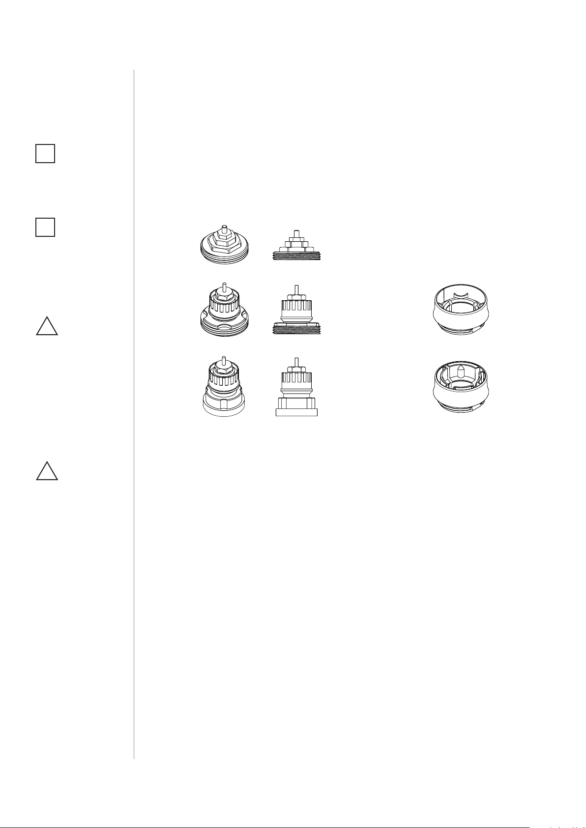
4. Depending on type of your thermostatic valve:
Proceed normally
M30 x 1.5
Use adapter:
Danfoss RTD-N
Use adapter:
Danfoss RA-N
5. Mount the device on the valve and tighten it by turning the cap
clockwise.
CAUTION
!
Do not cover or veil the
thermostatic head.
BASIC ACTIVATION
Page 5
#3: Pairing with HomeKit
1234
(FGBHT-001)
1. Open the Settings app on your iOS device.
2. Go to the Bluetooth® section, and turn the Bluetooth® on.
3. Place the accessory next to your iOS device.
4. Open a HomeKit compatible app of your choosing on your iOS
device.
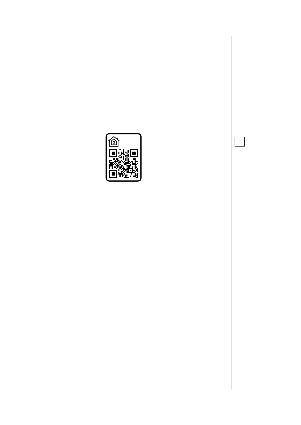
5. Find HomeKit Setup Code on the last page of Quick Start Guide
included in the box that looks like this:
5678
5
NOTE
i
You will nd the Setup
Code on the device’s
housing and on the
back of the Quick Start
Guide.
6. Start pairing with your HomeKit app.
7. Follow instructions displayed in the application.
PAIRING WITH HOMEKIT FGBHT001
Page 6
6
#4: Controlling the temperature
You can set temperature using app (10-30°C) or directly on the device
(16-24°C). During manual temperature change LED ring colour corresponds to the temperature set-point.
To check and change the temperature on the device:
1. Bring your hand close to the sphere.
2. LED ring will:
• Glow if temperature was set manually,
• Pulse slowly if device is in schedule mode,
• Pulse quickly if device is in override mode.
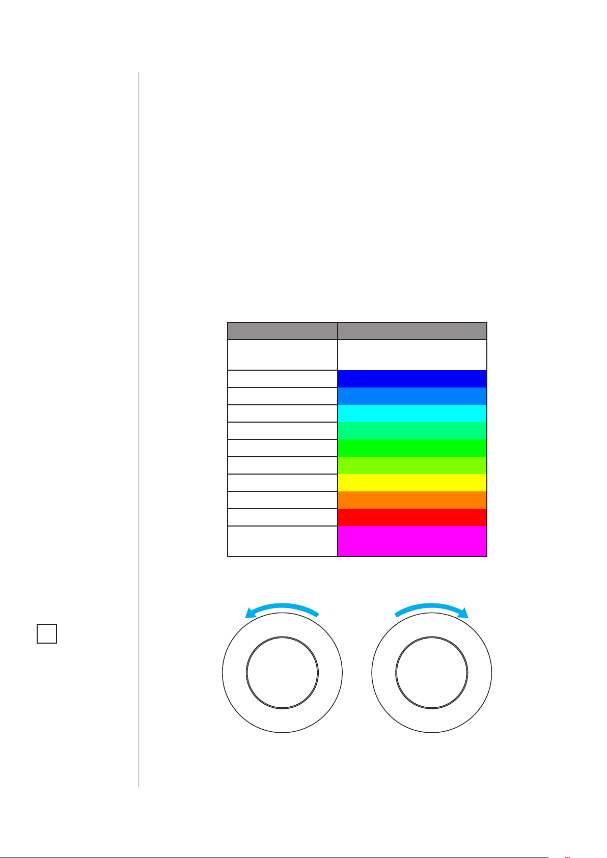
With colour depending on set temperature:
Temperature [°C] Colour
Valve closed
(anti-freeze)
16°C or lower Blue
17°C Azure
18°C Cyan
19°C Spring green
20°C Green
21°C Chartreuse
22°C Yellow
23°C Orange
24°C or higher Red
Valve fully opened
(30°C)
White
Magenta
3. Turn the sphere counter-clockwise to lower temperature or turn
clockwise to raise the temperature.
NOTE
i
If device is currently
in schedule, setting
temperature manually will override it (see
“Weekly schedule and
Override Mode” on
page 15).
4. Remove the hand from the sphere, after 5 seconds LED will fade
and new temperature will be set.
CONTROLLING THE TEMPERATURE
Lower temperature Raise temperature
Page 7
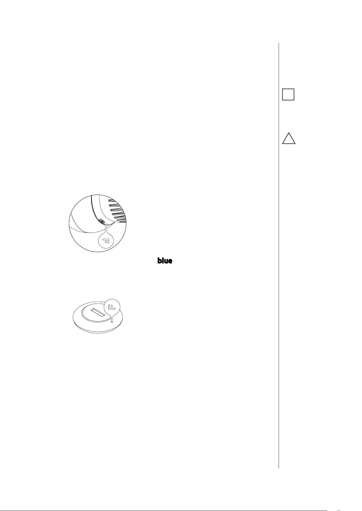
#5: Extra temperature sensor
7
The device can be used with an additional, dedicated temperature
sensor (FGBRS-001) to provide the best temperature regulation.
It can be placed anywhere in the room and the device will use it as a
reference point for the room temperature.
Before using, the sensor must be paired with the thermostatic head.
One thermostatic head can be paired with only one sensor, but one
sensor can be paired with up to three thermostatic heads.
To pair the FGBRS-001 with the device:
1. Use the included key to press and hold the button.
2. Release the button when you see blue LED colour.
NOTE
i
FGBRS-001 is the only
compatible external
temperature sensor.
CAUTION
!
This product is not a
toy. Keep away from
children and animals!
3. Quickly click the button to conrm, the LED ring will start blinking
blue.
4. Within 1 minute click button on the sensor.
5. The LED ring on thermostatic head will glow green to conrm successful pairing.
6. Place the sensor in same room as head, no further than 5 meters
from it.
To remove all paired heads:
1. Press and hold the button on the sensor for 2 seconds.
2. LED on the sensor will blink 3 times to conrm unpairing.
EXTRA TEMPERATURE SENSOR
Page 8

8
#6: Dismounting the device
Before dismounting, the device must be put in Standby Mode to
ensure safe removal. See chapter “Standby Mode” on page 12 for
more information.
To dismount the device:
1. Use the included key to press and hold the button.
2. Release the button when you see cyan LED colour.
3. Quickly click the button to conrm.
4. Wait for the LED to stop blinking.
5. Turn the cap counter-clockwise and remove adapter if used.
6. Store the device in temperature: -10°C to 25°C.
DISMOUNTING THE DEVICE
Page 9

#7: Menu
Menu allows to perform important conguration and maintenance
actions. In order to use the menu:
1. Use the included key to press and hold the button.
2. Release the button when you see desired LED colour:
Colour Action
Blue pair dedicated temperature sensor
Red
White perform head calibration
Cyan put device in Standby Mode
Yellow factory reset
enable/disable local control protection
9
3. Quickly click the button to conrm.
MENU
Page 10

10
#8: Local protection
After enabling the local control protection changing temperature directly on the device (by turning it) will not be possible.
Enabling local protection is recommended if you want to prevent accidental temperature change, e.g. by children. Local protection can
be enabled/disabled manualy or via app.
When attempting to change temperature if local protection is enabled:
• The device will not set new temperature,
• The LED ring will blink red 3 times.
To change the temperature use the app or disable the local protection.
To enable/disable local protection:
1. Use the included key to press and hold the button.
2. Release the button when you see red LED colour.
3. Quickly click the button to conrm.
LOCAL PROTECTION
Page 11

#9: Head calibration
11
Calibrating the device to your radiator valve is required for proper
controlling the temperature.
Calibration is performed:
• Automatically, after 10 minutes from turning on if no operation on
the device has been made*,
• Automatically, after 10 minutes from last manual state change*,
• Manually, using the menu (see below),
• Using Settings in FIBARO for HomeKit Devices app,
• After setting the temperature in FIBARO for HomeKit Devices
app*.
To perform calibration using the menu:
1. Use the included key to press and hold the button.
NOTE
i
Calibration cannot
be performed while
the device is being
charged.
CAUTION
!
If calibration is not
successfully completed, device will be unable to work correctly.
* Only at rst installation, after factory
reset or after exiting
Standby Mode.
2. Release the button when you see white LED colour.
3. Quickly click the button to conrm.
HEAD CALIBRATION
Page 12

12
#10: Standby Mode
In Standby Mode the device is in deep sleep state allowing for safe
dismounting, transporting and low as possible battery consumption.
The device is shipped in Standby Mode.
Entering the device in Standby Mode will not factory reset the device
nor will result in loosing any data, but calibration and sensor pairing
(after long Standby) is lost.
To enter Standby Mode:
1. Use the included key to press and hold the button.
2. Release the button when you see cyan LED colour.
3. Quickly click the button to conrm.
4. Wait for the LED to stop blinking.
To exit Standby Mode click the button once, the device will enter
rst installation procedure.
STANDBY MODE
Page 13

#11: Factory reset
Reset procedure allows to restore the accessory back to its factory
settings, including HomeKit and extra temperature sensor pairing
and device conguration.
To perform factory reset:
1. Use the included key to press and hold the button.
13
2. When the LED ring glows yellow, release the button.
3. Quickly click the button to conrm.
4. After nishing resetting the device will be put in Standby Mode.
Click the button to activate it again.
FACTORY RESET
Page 14

14
#12: Battery and charging
CAUTION
!
Make sure you are using
certied charger Class
II, marked which
complies with parameters specied in the
manual.
CAUTION
!
Do not leave the device unattended while
charging.
CAUTION
!
Set the device to OFF
(white) before charging or dismount the
thermostatic head if
not possible.
NOTE
i
The device is equipped with a rechargeable lithium-polymer battery pack that can be charged via micro-USB port using standard 5V
charger (not included).
When battery is low the LED ring will start to blink red. The device
will also report low battery status of itself and dedicated temperature
sensor (if paired) to the controller.
The device does not operate the valve and maintains the last valve
position until fully charged.
To charge the battery:
1. Connect charger to the micro-USB port.
2. During charging the LED ring will pulse red and valve control will
be disabled.
3. When LED starts pulsing green, disconnect the charger.
4. The device will restore its previous operation.
Do not use cables longer than 3 meters for
charging the device.
CAUTION
!
Make sure the device
won’t discharge during the heating season
or it may cause high
temperatures!
BATTERY AND CHARGING
Page 15

#13: Weekly schedule and
Override Mode
The device allows to create heating schedule to manage temperature
in the room throughout the week. Schedule is created via app. Up to
50 dierent rules can be created in schedule.
To create rule user should specify:
• Day of the week,
• Starting time (hour and minute),
• One of four available modes:
1. Away mode – 10-29.5°C (16.5°C by default)
2. Eco mode – 10-29.5°C (19.5°C by default)
15
3. Comfort mode – 10-29.5°C (21.5°C by default)
4. Comfort Plus mode – 10-29.5°C (23.5°C by default)
Override Mode is a special type of mode that overrides schedule.
Override Mode starts right after setting it for xed duration (4 hours
by default). Duration can be changed in FIBARO app.
To start Override Mode set temperature by turning the knob or
change the temperature via app, while schedule is active. LED ring
will pulse quickly with selected colour.
To exit Override Mode grab knob with your hand for 5 seconds.
There are 3 special types of override modes:
Vacation mode is a special override mode that sets constant temperature (between 10-29.5°C) and works until turned o.
Valve closed (anti-freeze) is a mode where valve opens only to prevent freezing. It works until turned o.
CAUTION
!
Working in override
mode for a week or
longer turns o schedule mode.
Valve fully opened (30°C) is a mode where the temperature is raised
to the maximum value, device does not regulate the temperature and
valve is fully opened. It works until turned o.
WEEKLY SCHEDULE AND OVERRIDE MODE
Page 16

16
#14: Congurable parameters
1. External sensor status (read-only)
Status of the connection with external temperature sensor.
Available settings: 0 – unpaired
1 – paired
Default setting: 0 (unpaired)
2. Lock physical control
Parental lock of manual control. When enabled the device prevents
changing the temperature by turning the knob until it is disabled by
this parameter or from the menu.
Available settings: 0 – manual control enabled
1 – manual control disabled
Default setting: 0 (enabled)
3. Calibration
Forcing automatic calibration of the device.
Available settings: 0 – device is not during calibration
1 – force autocalibration
Default setting: 0
CONFIGURABLE PARAMETERS
Page 17

#15: Status faults
The device reports the status of detected errors in the form of
a bit mask (status faults). Values can be combined, for example:
code with value 5 (1+4) means low battery and calibration error
were detected.
Code Status
0x01 Low battery of external sensor - battery level
of extra temperature sensor is low. Change the
battery.
0x02 Hardware fault - fault of the device. Device will
try to calibrate again.
0x04 Calibration error* - unsuccessful calibration.
Device is unable to work properly.
17
* After every Factory Reset and Standby Mode device reports
calibration error (status dissapears after correct calibration).
STATUS FAULTS
Page 18

18
#16: Specications
NOTE
i
Charger type: Unit shall
be supplied by a source
certied as Limited
Power Source (LPS) as
dened in clause 2.5
of IEC60950-1 2nd edition + Amd. 1 + Amd. 2.
CAUTION
!
SELV power supply
(USB supply) is used
only for battery charging. The device does
not operate the valve
during the charging.
Power supply:
Charging port:
Charger voltage (not included):
Minimum charger current
(not included):
Operating temperature:
Storage temperature
(standby mode)
Maximum water temperature:
Temperature measuring accuracy:
Regulator class:
Device Firmware Class:
Motor protection:
Actuator action:
Actuator stroke:
Purpose of control:
Construction of control:
Degree of protection by enclosure:
Classication of control according
to protection against electric shock:
Action type:
Control pollution degree:
Rated impulse voltage:
Dimensions
(Diameter x Length):
EU Directive compliance:
3.7V Li-Poly battery pack
(non-replaceable)
micro-USB
5V DC (±5%)
0.5A
0–40°C
-10–25°C
90°C
0.5°C (within 0–40°C range)
Type 1 class
A-grade
Impedance Protected
Linear variable position actuator
5mm
Operating control
Integrated control
IP20
Class III
type 1
pollution degree 2
330V (when connected to the USB
power supply)
56 x 74 mm (without the adapter)
56 x 87 mm (with the adapter)
RoHS 2011/65/EU
RED 2014/53/EU
SPECIFICATIONS
Page 19

For communication with the controller:
19
Radio protocol:
Radio frequency band:
Maximum transmit power:
For communication with the extra sensor (FGBRS-001):
Radio protocol:
Radio frequency band:
Maximum transmit power:
Bluetooth® low energy (4.2)
2.4 GHz ISM band
EIRP up to 6dBm
Bluetooth® low energy (4.2)
2.4 GHz ISM band
EIRP up to 6dBm
SPECIFICATIONS
Page 20

20
#17: Sensor specication
(FGBRS-001)
CAUTION
!
Using batteries other
than specied may result in explosion. Dispose of properly, observing environmental
protection rules.
CAUTION
!
CR2032 coin cell battery is harmful if swallowed!
Power supply:
Operating temperature:
Storage temperature:
Temperature measuring
accuracy:
Dimensions
(Diameter x Height):
Radio protocol:
Radio frequency band:
Maximum transmit power:
EU Directive compliance:
CR2032, 3.0V battery (included)
0–40°C
-10–40°C
0.5°C (within 0–40°C range)
38 x 12 mm
Bluetooth® low energy (4.2)
2.4 GHz ISM band
EIRP up to 6.5dBm
RoHS 2011/65/EU
RED 2014/53/EU
SENSOR SPECIFICATION FGBRS001
Page 21

#18: Regulations
Legal Notices
All information, including, but not limited to, information regarding the
features, functionality, and/or other product specication are subject
to change without notice. Fibaro reserves all rights to revise or update
its products, software, or documentation without any obligation to notify any individual or entity.
FIBARO and Fibar Group logo are trademarks of Fibar Group S.A.
The Bluetooth word mark and logos are registered trademarks owned
by Bluetooth SIG, Inc. and any use of such marks by Fibar Group S.A. is
under license.
Apple, iPhone, iPad, iPad Air, and iPod touch are trademarks of Apple
Inc., registered in the U.S. and other countries. HomeKit is a trademark
of Apple Inc.
All other brands and product names referred to herein are trademarks
of their respective holders.
Use of the Works with Apple HomeKit logo means that an electronic accessory has been designed to connect specically to iPod touch,
iPhone, or iPad, respectively, and has been certied by the developer to
meet Apple performance standards. Apple is not responsible for the operation of this device or its compliance with safety and regulatory standards.
21
Warning
This product is not a toy. Keep away from children and animals! CR2032
coin cells are harmful if swallowed!
Declaration of conformity
Hereby, Fibar Group S.A. declares that the device is in compliance with the essential requirements and other relevant
provisions of Directive 2014/53/EU. The full text of the EU
declaration of conformity is available at the following internet address:
www.manuals.baro.com
WEEE Directive Compliance
Device labelled with this symbol should not be disposed with
other household wastes. It shall be handed over to the applicable collection point for the recycling of waste electrical and
electronic equipment.
REGULATIONS
 Loading...