

USA
Fibaro RGBW Controller is a universal, Z-Wave compatible RGB /
RGBW controller. Fibaro RGBW Controller uses PWM output
signal, which enables it to control LED, RGB, RGBW strips,
halogen lights and fans. Controlled devices may be powered by 12
or 24 VDC. In addition the device supports up to four, 0V - 10V
analog sensors, such as temperature sensors, humidity sensors,
wind sensors, air quality sensors, light sensors etc. All IN and OUT
terminals may be user configured for LED control or 0V-10V signal
readouts.
Specifications
Power Supply:
Rated output power:
PWM output frequency:
Electricity consumption:
Radio signal power:
For installation in boxes:
Max load (e.g. halogen
bulbs):
Radio protocol:
Radio frequency:
Range:
Operational temperature:
Dimensions (L x W x H):
12 V DC
24 V DC
combined 12A (sum of all
connected output channels); 6A
for single output channel
244 Hz
0,3W
1mW
Ø≥50 mm
at 12V - 144W combined,
at 24V - 288W combined.
Z-Wave
868,4 MHz EU;
908,4 MHz US;
921,4 MHz ANZ;
869,2 MHz RU;
up to 50m outdoors / up to 30m
indoors; depending on terrain and
building structure
0 - 40
o
C
42 x 37 x 17 mm
Operating Manual
FIBARO RGBW Controller
FGRGBWM-441-USA-A-v1.01
Technical Information
• Controlled by Fibaro System devices or any Z-Wave controller
• Microprocessor controlled
• Executive element: transistor
• Active and historic (average) power consumption measuring
I General Information About Fibaro System
Fibaro is a wireless system, based on Z-Wave technology. Fibaro
provides many advantages when compared to similar systems. In
general, radio systems create a direct connection between the
receiver and transmitter. However, the radio signal is weakened by
various obstacles located in its path (apartment walls, furniture,
etc.) and in extreme cases it fails to transfer required data. The
advantage of Fibaro System is that its devices, apart from being
transmitters and signal receivers, also duplicate signal. When a
direct connection path between the transmitter and the receiver
cannot be established, the connection may be achieved through
other intermediate devices.
Fibaro is a bi-directional wireless system. This means that the
signal is not only sent to the receivers but also the receivers send
the confirmation of its reception. This operation confirms their
status, which checks whether they are active or not.
Safety of the Fibaro System transmission is comparable to the
safety of transmission in data bus wired systems.
Fibaro operates in the free bandwidth for data transmission. The
frequency depends on radio regulations in individual countries.
Each Fibaro network has its own unique network identification
number (home ID), which is why it is possible to co-operate two or
more independent systems in a single building without any
interference.
II Device Applications
Note
1) Please contact your local supplier for the
current rates.
2) Fibaro RGBW Controller stores consumed
electricity data on its memory, which means
disconnecting the module from voltage supply
does not erase the data.
i
Although Z-Wave is quite a new technology, it has already become
recognized and officially a binding standard, similarly to Wi-Fi.
Many manufacturers in various industries offer solutions based on
Z-Wave technology, guaranteeing their compatibility. This means
that the system is open and it may be extended in the future. Find
more information at www.fibaro.com.
Fibaro generates a dynamic network structure. After Fibaro System
is switched on, the location of its individual components is
automatically updated in real-time through status confirmation
signals received from devices operating in a "mesh" network.
Fibaro RGBW Controller may control:
• 12 / 24VDC powered RGB strips
• 12 / 24VDC powered RGBW strips
• 12 / 24VDC powered LED strips, bulbs, etc.
• 12 / 24VDC powered halogen lights
• 12 / 24VDC powered low output power fans
Additional features:
• 0-10V sensors signal readouts,
• 0-10V potentiometer signal readouts, and managing outputs
accordingly,
• controlled by momentary or toggle switches
III Installing the device
1. Before installation ensure the voltage supply is disconnected.
2. Connect Fibaro RGBW Controller according to wiring diagram.
First, connect outputs (R,G,B,W) RGB/RGBW/LED diodes or
Halogen lights, or inputs (I1-I4). Second, connect voltage supply.
Note the device must be powered by a dedicated stabilized power
adapter.
3. Arrange the antenna (find tips below wiring diagrams).
4. Turn the voltage on.
5. Include the module into the Z-Wave network.
Warning!
1) Fibaro RGBW Controller is dedicated to operate in low voltage
circuits of 12VDC or 24VDC. Connecting higher voltage load may
result in Fibaro RGBW Controller damage.
2) Fibaro RGBW Controller must be powered by the same voltage
as the connected light source. I.e. if controlling 12V LED strip, the
module must be connected to 12V power supply. Similarly, if
controlling 24V RGBW strip, Fibaro RGBW Controller must be
powered by 24V voltage supply.
3) Fibaro RGBW Controller has 0-10V input. There is no 0-10V
output. Output is controlled by PWM at 244Hz.
4) Fibaro RGBW Controller must be powered by 12VDC or 24 VDC
stabilized power supply with outputs load capacity matched to loads
voltage.
5) Sensors using 0-10V interface use wire connection to inputs I1 I4. Maximum length of 0-10V connection line is 10 m. Observe
sensor's manufacturer recommendations towards 0-10V line
diameter.
6) In case of connecting long RGBW/RGB/LED strips voltage drops
may occur, resulting in lower light brightness further from R/G/B/W
outputs. To eliminate this effect it's recommended to connect few
shorter strips in parallel connection instead of one long strip
connected serially.
Maximum recommended wire length, used to connect R/G/B/W
outputs with a RGBW/RGB/LED strip is 10 m. Observe connected
loads manufacturer recommendations towards connection wire
diameter.
IV Z-Wave network inclusion
Fibaro RGBW Controller may be included into Z-Wave network
using B-button or any switch key connected to I1-I4 inputs. The
device has an auto-inclusion function implemented and can be
included into the Z-Wave network automatically, by simply
connecting the voltage supply.
Adding Fibaro RGBW Controller to the Z-Wave network in
auto-inclusion mode:
1. Make sure Fibaro RGBW Controller is not connected to voltage
supply and located within direct range of the main controller.
2. Set the Z-Wave network main controller into learning mode (see
Z-Wave network controller operating manual).
3. Connect voltage supply to auto-include Fibaro RGBW Controller.
4. Fibaro RGBW Controller will be automatically recognized and
included in the Z-Wave network.
To disable auto-inclusion press the B-button briefly, after
connecting Fibaro RGBW Controller to voltage supply.
Adding Fibaro RGBW Controller to the Z-Wave network in manual
inclusion mode:
1. Connect Fibaro RGBW Controller to voltage supply.
2. Set the Z-Wave network main controller into learning mode (see
Z-Wave network controller operating manual).
3. Triple click the B-button or any switch connected to I1-I4 inputs.
4. Fibaro RGBW Controller will be automatically recognized and
included in the Z-Wave network.
V Z-Wave network exclusion
Excluding the Fibaro RGBW Controller from the Z-Wave network:
1. Connect Fibaro RGBW Controller to voltage supply.
2. Set the Z-Wave network main controller into learning mode (see
Z-Wave network controller operating manual).
3. Triple click the B-button or any switch connected to I1-I4 inputs.
VI Resetting Fibaro RGBW Controller
Reset procedure clears the Fibaro RGBW Controller's memory,
including Z-Wave network controller information, energy
consumption data and 5 user-defined programs.
Resetting Fibaro RGBW Controller:
1. Disconnect voltage supply.
2. Press and hold the B-button located inside Fibaro RGBW
Controller's casing.
3. Connect voltage supply still holding the B-button.
4. Release the B-button.
5. B channel will turn on (blue channel).
6. Disconnect power supply.
Warning
Resetting the RGBW Controller does not mean it
has been removed from Z-Wave network
controller's memory. Remove the RGBW
Controller from Z-Wave network controller's
memory before carrying out the resetting
procedure.
VII Fibaro RGBW Controller operating modes
The device may be controller by momentary or toggle switches.
Fibaro RGBW Controller may serve as 0-10V input module and
operate with any 0-10V sensor, e.g. temperature sensors, wind
speed/direction sensors, air quality sensors, light sensors, etc.
Fibaro RGBW Controller offers fully configurable operating modes,
described in pt. X, user defined in parameter 14. Operating mode
is set during first configuration in Home Center 2 interface. Other
main controllers require dedicated setting of parameter 14. Refer to
p.VIII and IX for operating modes detailed description.
Fibaro RGBW Controller's operating modes:
1) RGB/RGBW - controlling RGBW/RGB/LED strips or Halogen
lights based on signals from switches connected to I1-I4 inputs.
User may precisely set illumination colour.
2) IN/OUT - all inputs and outputs may be freely configured by the
user. All inputs I1 - I4 and outputs R, G, B, W may be independently
configured by the user. Depending on configuration the device will
be presented in Home Center 2 interface as sensors or dimmers.
User defines sensor type and its operating range. If a given
channel operates in OUT mode, user may control e.g. LED or
Halogen lamp brightness.
All of the operating modes are described in fig. 5
VIII Manual RGB/RGBW operating mode
Fibaro RGBW Controller has 4 controllable inputs I1-I4, configured
by default to work with push buttons. Each input controls
designated channel, i.e.:
- I1 controls R channel.
- I2 controls G channel.
- I3 controls B channel.
- I4 controls W channel.
Controlling I1-I4 inputs is achieved by connecting ground wire
(GND) to specified channel (see scheme).
Further, parameter's 14 settings allow for following type of manual
control:
1) NORMAL mode - controlling output assigned to given input
terminal. In this setting outputs will be controlled independently
from one another, e.g. allowing for free adjusting each colours
saturation. Double click will set a given channel's saturation to
100%. This operating mode works with momentary and toggle
switches.
2) BRIGHTNESS mode - all outputs are controlled together, i.e.
one switch controls brightness of all channels at the same time.
This operating mode works with momentary and toggle switches.
3) RAINBOW mode - 3. mode - all outputs are controlled together
giving a transition of full colours spectrum. RAINBOW mode works
with momentary switches only.
IX IN/OUT mode - 0-10V inputs, PWM outputs
Fibaro RGBW Controller has 4 controllable, analog inputs I1 - I4,
allowing for 0-10V analog signal interpretation. This functionality
may be used in operation with analog sensors and potentiometers.
What's more, in IN/OUT mode all inputs and outputs may be
configured independently, e.g. I1 may be configured as 0-10V
sensor input and I2-I4 may control LED strip or Halogen lamps.
Another option is to configure I1 as 0-10V input and connect 0-10V
potentiometer to it, and connecting Halogen lamps to R output. At
the same time, other inputs may work with 0-10V sensors.
X First configuration.
Operating through the Z-Wave network
After inclusion to the Z-Wave network, Home Center 2 interface will
present the module as un-configured device.
To configure the device please follow the steps below:
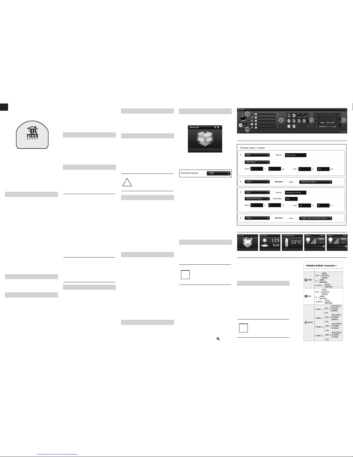
1) Specify controlled device - RGBW, RGB, IN/OUT (further
described in pt. IX)
If RGBW/RGB mode is chosen, device icon will be as follows:
Control window description:
1 - Currently chosen colour.
2 - ON/OFF button.
3 - Colours slider - allows for choosing any colour in RGB scale,
white colour saturation and all colours brightness.
4 - Favourite colours section.
5 - Predefined colour programs.
2) 2. As described in pt. IX IN/OUT mode allows for configuring each
IN/OUT independently.
Fig 3 shows an example configuration: I1 configured as a light
intensity sensor; I2 configured as a dimmer, e.g. controlling LED
strip; I3 configured as a temperature sensor; I4 configured as a
dimmer, e.g. controlling halogen lamp.
As shown in Fig.3 inputs set to work in analog mode require
following configuration:
- Actual voltage range (e.g. 0-10V, 1-10V, 0-5V)
- Measured unit range (e.g. 0-50oC for temperature sensor)
Above information can be found in sensor's operating manual.
Device icons in the main controllers interface will reflect the above
configuration settings, e.g. light sensor, temperature sensor, two
OUT devices i.e. LED strips or Halogen bulbs, as shown in fig.4.
Fig. 2 Fibaro RGBW Controller control window
Fig 1 - Unconfigured RGB device icon
Fig 4 - IN / OUT controlled devices icons
XI Associations
Through an association Fibaro RGBW Controller may control
another Z-Wave network device, e.g. another RGBW Controller,
Wall Plug, Dimmer, Relay Switch or Roller Shutter. Such a control
is done via switch keys connected to I1-I4 outputs only. Operation
through the Z-Wave network doesn't trigger the associated
devices.
Note
Association allows for direct communication
between Z-Wave network devices. Main controller
does not take part in such communication. Using
this mechanism, Fibaro RGBW Controller may
communicate with other devices even when the
main controller is damaged, e.g. in fire.
i
Fibaro RGBW Controller provides five association groups:
I association group assigned to I1 input - sends control frame to
associated devices each time the device state changes. (ON /
OFF)
II association group assigned to I2 input - sends control frame to
associated devices each time the device state changes. (ON /
OFF)
III association group assigned to I3 input - sends control frame to
associated devices each time the device state changes. (ON /
OFF)
IV association group assigned to I4 input - sends control frame to
associated devices each time the device state changes. (ON /
OFF)
V association group reports device status. Only one device may
be assigned to this group, main controller by default. It's not
recommended to modify this group's settings.
Fibaro RGBW Controller allows for controlling up to 5 regular
devices (opposed to multi channel devices) per each association
group, out of which 1 field is reserved for the main controller.
To add an association, (using Home Center 2 interface) go to
device settings and click the following icon:
Select the "device options" tab. Then specify to which group and
what devices are to be associated. Sending relevant information to
devices added to association groups may take even a few minutes.
XII Current load and energy consumption
1) Fibaro RGBW Controller allows for the current load and power
consumption monitoring. Data is sent to the main controller, e.g.
Home Center 2. Measuring is carried out by an independent
microprocessor dedicated exclusively for the purpose, assuring
maximum accuracy and precision. The microprocessor is factory
calibrated.
Electric power - power consumed by an electric device in an
instant, in Watts (W).
Electric energy - energy consumed by a device through a time
period. Most commonly measured in kilowatt-hours (kWh). One
kilowatt-hour is equal to one kilowatt of power consumed over a
period of one hour, 1kWh = 1000 Wh.
Fig 3 - IN / OUT mode settings screen
Resetting electricity consumption memory - reset the device
(see pt. VI) or choose reset electricity consumption memory option
from the main controller's menu.
Home Center 2 controller allows for choosing command frame sent
to associated devices:
Normal (Dimmer) - synchronization with dimmer
Normal (RGBW) - synchronization with other producers RGBW
controllers
Normal (RGBW-FIBARO) - synchronization with Fibaro RGBW
Controllers
Fig 5 - Modes of operation
GLOSSARY OF TERMS:
• INCLUSION (Adding) - a device sends "Node Info" frame, to
enable user to add it to Fibaro system (HC 2 or HC Lite). To send
Node Info frame and put device in permanent listening mode press
B button 3 times.
• EXCLUSION (Removing) - removing a device from the Fibaro
radio system.
• ASSOCIATION - controlling other devices of Fibaro system
© 2014 Fibar Group Sp. z.o.o. All rights reserved.
Distributed by Fibaro
1040 East Lake Ave, Glenview, IL 60025, USA
www.fibaro.com
!
XIII Advanced configuration
GENERAL:
1. ALL ON / ALL OFF function activation
Default setting: 255
0 - ALL ON inactive, ALL OFF inactive
1 - ALL ON inactive, ALL OFF active
2 - ALL ON active, ALL OFF inactive
255 - ALL ON active, ALL OFF active
Parameter size: 1 [byte]
6. Associations command class choice
Default setting: 0
0 - NORMAL (DIMMER) - BASIC SET/SWITCH_MULTILEVEL_-
START/STOP
1 - NORMAL (RGBW) - COLOR_CONTROL_SET/START/STOP_STATE_CHANGE
2 - NORMAL (RGBW) - COLOR_CONTROL_SET
3 - BRIGHTNESS - BASIC SET/SWITCH_MULTILEVEL_STAR-
T/STOP
4 - RAINBOW (RGBW) - COLOR_CONTROL_SET
Parameter size: 1 [byte]
IN/OUT:
8. Output state change mode (applies only to operation via
Z-Wave controller).
Default setting: 0
0 - MODE1 (related parameters: 9-step value, 10-time between
steps)
1 - MODE2 (related parameters: 11-time to change value, relevant
for RGB/RGBW)
Parameter size: 1 [byte]
MODE1
Example: change saturation level from 0% to 99%
Parameter 9: Step = 5
Parameter 10: Time between steps: 10ms
9. Step value (relevant for MODE1)
Default setting: 1
Available settings: 1 - 255
Parameter size: 1[byte]
10. Time between steps (relevant for MODE1)
Default setting: 10 (10ms)
0 - immediate change of state
1-60000 - (1-60000 ms)
MODE2
Example: change saturation level from 0% to 99%
Parameter 11: time for changing from start to end value = 500sec
11. Time for changing from start to end value
Default setting: 67 (3s)
0 - immediate change
1-63 - 20-126- [ms] value*20ms
65-127 - 1-63 [s] [value-64]*1s
129-191 - 10-630[s] [value-128]*10s
193-255 - 1-63[min] [value-192]*1min
Parameter size: 1[byte]
12. Maximum brightening level
Default setting: 255
Available settings: 3-255
Parameter size: 1[byte]
13. Minimum dim level
Default setting: 2
Available settings: 3-255
Parameter size: 1[byte]
14. Inputs / Outputs configuration - relevant for main
controllers other than Home Center 2 only
Default setting: 4369 Controlled device: RGBW, momentary switch
inputs (NORMAL MODE)
Each 4bit refer to given IN/OUT (channel) settings
Note
The maximum leven cannot be lower than
minimum level.
i
Channel 1
(4 bit)
Channel 2
(4 bit)
Channel 3
(4 bit)
Channel 4
(4 bit)
0000 0000 0000 0000
.... .... .... ....
1111 1111 1111 1111
If RGB/RGBW mode is chosen, settings for all 4 channels are
identical. Settings marked with X are forbidden and cannot be sent
to the module.
Settings available for single channel
15. Double-click feature (set channel to 100%)
Default setting: 1
0 - double-click disabled
1 - double-click enabled
Parameter size: 1[byte]
16. Memorize device status at power cut. Device will be set to
status memorized before power cut.
Default setting: 1
0 - device does not memorize its status at the power cut. Load is
disconnected.
1 - device memorizes its status at the power cut. Load will be set
to the status from before power cut (parameters, current outputs
status, energy)
Parameter size: 1[byte]
ALARM:
30. Alarm of any type (general alarm, flood alarm, smoke
alarm: CO, CO2, temperature alarm).
Default setting: 0
0 - INACTIVE - the device doesn't respond to alarm frames
1 - ALARM ON - the device turns on once alarm is detected (all
channels set to 99%)
2 - ALARM OFF - the device turns off once alarm is detected (all
channels set to 0%)
3 - ALARM PROGRAM - alarm sequence turns on (program
selected in parameter 38)
Parameter size: 1[byte]
38. Alarm sequence program
Default setting: 10
1 - 10 (1-10 specifies alarm program number)
Parameter size: 1[byte]
39. Active PROGRAM alarm time
Default setting: 600
1-65534 (1s-65534s)
Parameter size: 2[byte]
REPORTS:
42. Command class reporting Outputs status change
Default setting: 0
0 - reporting as a result of inputs and controllers actions (SWITCH
MULTILEVEL)
1 - reporting as a result inputs actions (SWITCH MULTILEVEL)
2 - reporting as a result of inputs actions (COLOR CONTROL)
Parameter size: 1[byte]
43. Reporting 0-10v analog inputs change threshold.
Parameter defines a value by which input voltage must change in
order to be reported to the main controller. New value is calculated
based on last reported value:
Default setting: 5 (0,5V)
1-100 - (0,1 - 10V)
Parameter size: 1[byte]
44. Power load reporting frequency (if last reported value differs
from the current value). Reports will also be sent in case of polling.
Default setting: 30 (30s)
1 - 65534 (1s-65534s) - time between reports,
0 - reports are not sent. Reports will only be sent in case of polling
or at turning OFF the device.
Parameter size: 2[byte]
45. Reporting changes in energy consumed by controlled
devices. New, reported energy value is calculated based on last
reported value.
Default setting: 10 (0,1 kWh)
1 - 254 (0,01kWh - 2,54kWh)
0 - changes in consumed energy will not be reported. Reports will
be sent only in case of polling.
Parameter size: 1[byte]
OTHER:
71. Response to BRIGHTNESS set to 0%
Default setting: 1
0 - illumination colour set to white (all channels controlled together)
1 - last set colour is memorized
Parameter size: 1[byte]
72. Starting predefined program when device set to work in
RGB/RGBW mode (parameter 14) - relevant for main
controllers other than Home Center 2 only.
Default setting: 1
1-10 animation program number
Parameter size: 1[byte]
73. Triple click action
Default setting: 0
0 - NODE INFO control frame is sent,
1 - starting favourite program
Parameter size: 1[byte]
1. The Guarantee is provided by FIBAR GROUP Sp. z o.o.
(hereinafter "Manufacturer"), based in Poznan, ul. Lotnicza 1; 60-421
Poznan, entered in the register of the National Court Register kept
by the District Court in Poznań, VIII Economic Department of the
National Court Register, no. 370151, NIP 7811858097, REGON:
301595664.
2. The Manufacturer is responsible for equipment malfunction
resulting from physical defects (manufacturing or material) of the
Device for 12 months from the date of its purchasing.
3. During the Guarantee period, the Manufacturer shall remove any
defects, free of charge, by repairing or replacing (at the sole
discretion of the Manufacturer) any defective components of the
Device with new or regenerated components, that are free of
defects. When the repair impossible, the Manufacturer reserves the
right to replace the device with a new or regenerated one, which shall
be free of any defects and its condition shall not be worse than the
original device owned by the Customer.
4. In special cases, when the device cannot be replaced with the
device of the same type (e.g. the device is no longer available in the
commercial offer), the Manufacturer may replace it with a different
device having technical parameters similar to the faulty one. Such
activity shall be considered as fulfilling the obligations of the
Manufacturer. The Manufacturer shall not refund money paid for the
device.
5. The holder of a valid guarantee shall submit a guarantee claim
through the guarantee service. Remember: before you submit a
guarantee claim, contact our technical support using telephone or
e-mail. More than 50% of operational problems is resolved remotely,
saving time and money spent to initiating guarantee procedure. If
remote support is insufficient, the Customer shall fill the guarantee
claim form (using our website - www.fibargroup.com) in order to
obtain claim authorization.
When the guarantee claim form is submitted correctly, the Customer
shall receive the claim confirmation with an unique number (Return
Merchandise Authorization -RMA).
6. The claim may be also submitted by telephone. In this case, the
call is recorded and the Customer shall be informed about it by a
consultant before submitting the claim. Immediately after submitting
the claim, the consultant shall provide the Customer with the claim
number (RMA-number).
7. When the guarantee claim form is submitted correctly, a
representative of the Authorised Guarantee Service (hereinafter as
"AGS") shall contact the Customer.
8. Defects revealed within the guarantee period shall be removed
not later than 30 days from the date of delivering the Device to AGS.
The guarantee period shall be extended by the time in which the
Device was kept by AGS.
9. The faulty device shall be provided by the Customer with complete
standard equipment and documents proving its purchase.
XIV Guarantee
10. Parts replaced under the guarantee are the property of the
Manufacturer. The guarantee for all parts replaced in the guarantee
process shall be equal to the guarantee period of the original device.
The guarantee period of the replaced part shall not be extended.
11. Costs of delivering the faulty device shall be borne by the
Customer. For unjustified service calls, the Service may charge the
Customer with travel expenses and handling costs related to the
case.
12. AGS shall not accept a complaint claim only when:
• the Device was misused or the manual was not observed,
• the Device was provided by the Customer incomplete, without
accessories or nameplate,
• it was determined that the fault was caused by other reasons than
a material or manufacturing defect of the Device
• the guarantee document is not valid or there is no proof of
purchase,
13. The Manufacturer shall not be liable for damages to property
caused by defective device. The Manufacturer shall not be liable for
indirect, incidental, special, consequential or punitive damages, or
for any damages, including, inter alia, loss of profits, savings, data,
loss of benefits, claims by third parties and any property damage or
personal injuries arising from or related to the use of the Device.
14. The guarantee shall not cover:
• mechanical damages (cracks, fractures, cuts, abrasions, physical
deformations caused by impact, falling or dropping the device or
other object, improper use or not observing the operating manual);
• damages resulting from external causes, e.g.: flood, storm, fire,
lightning, natural disasters, earthquakes, war, civil disturbance, force
majeure, unforeseen accidents, theft, water damage, liquid leakage,
battery spill, weather conditions, sunlight, sand, moisture, high or low
temperature, air pollution;
• damages caused by malfunctioning software, attack of a computer
virus, or by failure to update the software as recommended by the
Manufacturer;
• damages resulting from: surges in the power and/or telecommunication network, improper connection to the grid in a manner
inconsistent with the operating manual, or from connecting other
devices not recommended by the Manufacturer.
• damages caused by operating or storing the device in extremely
adverse conditions, i.e. high humidity, dust, too low (freezing) or too
high ambient temperature. Detailed permissible conditions for
operating the Device are defined in the operating manual;
• damages caused by using accessories not recommended by the
Manufacturer
• damages caused by faulty electrical installation of the Customer,
including the use of incorrect fuses;
• damages caused by Customer's failure to provide maintenance and
servicing activities defined in the operating manual;
• damages resulting from the use of spurious spare parts or
accessories improper for given model, repairing and introducing
alterations by unauthorized persons;
• defects caused by operating faulty Device or accessories.
15. The scope of the guarantee repairs shall not include periodic
maintenance and inspections, in particular cleaning, adjustments,
operational checks, correction of errors or parameter programming
and other activities that should be performed by the user (Buyer).
The guarantee shall not cover natural wear and tear of the Device
and its components listed in the operating manual and in technical
documentation as such elements have a defined operational life.
16. If a defect is not covered by the guarantee, the Manufacturer
reserves the right to remove such defect at its sole discretion,
repairing the damaged or destroyed parts or providing components
necessary for repair or replacement.
17. This guarantee shall not exclude, limit or suspend the Customer
rights when the provided product is inconsistent with the purchase
agreement.
MSB LSB
Controlled
device
0
1
2
3
4
5
6
7
8
9
10
11
12
13
14
15
(RGBW)
X
(RGBW)
MOMENTARY
(NORMAL MODE)
(RGBW)
MOMENTARY
(BRIGHTNESS MODE)
(RGBW)
MOMENTARY
(RAINBOW MODE)
(RGBW)
TOGGLE
(NORMAL MODE)
(RGBW)
TOGGLE
(BRIGHTNESS MODE)
(RGBW)
TOGGLE W. MEMORY
(NORMAL MODE)
(RGBW)
TOGGLE W. MEMORY
(BRIGHTNESS MODE)
(IN)
ANALOG 0-10V
(SENSOR)
(OUT)
MOMENTARY
(NORMAL MODE)
(OUT)
X
X
(OUT)
(OUT)
TOGGLE
(NORMAL MODE)
(OUT) X
(OUT)
TOGGLE W/MEMORY
(NORMAL MODE)
0 0 0 0
0 0 0 1
0 0 1 0
0 0 1 1
0 1 0 0
0 1 0 1
0 1 1 0
0 1
1 1
1 0
0 0
1 0
0 1
1 0
1 0
1 0
1
1
1 1
0 0
1 1
0 1
1 1
1 0
1 1
1 1 (OUT)
X
This Device may be used with all devices
certified with Z-Wave certificate and should be
compatible with such devices produced by
other manufacturers.
Any device compatible with Z-Wave may be added
to Fibaro system.
i
FIBARGROUP
FIBARO
In case of any technical questions contact customer service centre
in your country.
www.fibaro.com
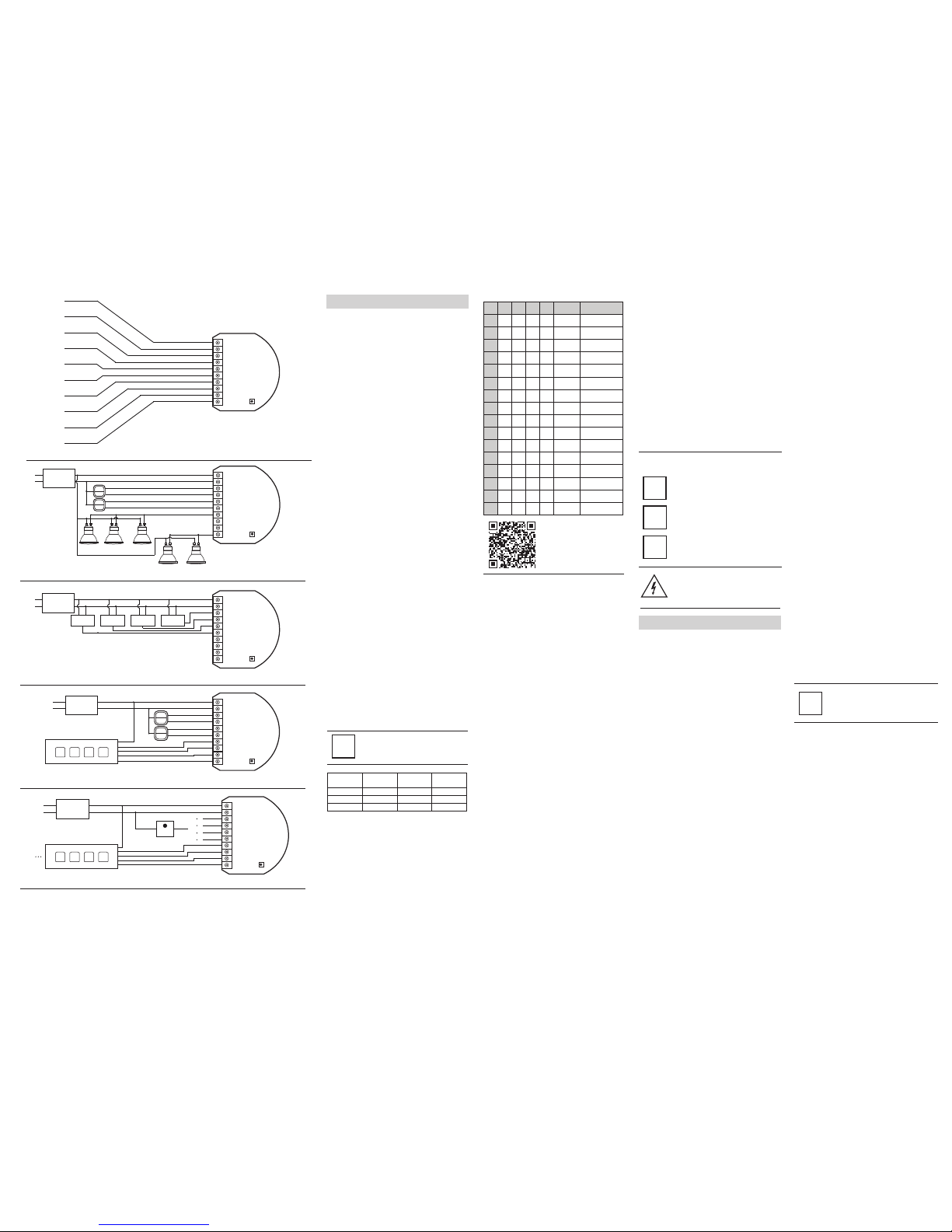
Fig. 6- Terminals description
Fig. 7 - Connecting halogen lighting
Fig. 8 - 0-10 V sensors wiring diagram
Fig. 9 - RGBW strip wiring diagram
Fig 10. - RGBW strip with 0-10 V potentiometer wiring diagram
NOTES FOR THE DIAGRAM
12/24VDC - power supply signal
GND - power supply ground signal
IN1 - potential free / 0-10V input 1
IN2 - potential free / 0-10V input 2
IN3 - potential free / 0-10V input 3
IN4 - potential free / 0-10V input 4
R - output assigned to IN1
G - output assigned to IN2
B - output assigned to IN3
W - output assigned to IN4
Note!
Parameter 14 recommended
settings, for controllers other than
Home Center 2, are available under
the following link:
http://manual.rgbw.fibaro.co.uk/
ras-rgbw-controller-en.pdf
Locate the antenna as far from metal elements as
possible (connecting wires, bracket rings, etc.) in
order to prevent interferences.
i
Metal surfaces in the direct vicinity of the antenna
(e.g. flush mounted metal boxes, metal door frames)
may impair signal reception!
i
TIPS FOR ARRANGING THE ANTENNA:
Do not cut or shorten the antenna - its length is
perfectly matched to the band in which the system
operates
i
Input type:
- ANALOG - sensor with analog, 0-10V interface. Impossible to
control from main controllers interface.
- MOMENTARY - momentary switch,
- TOGGLE - toggle switch,
- TOGGLE W/MEMORY - toggle switch (ON active for closing
switch terminals; OFF active for opening switch terminals)
Input operating mode (controlled with switch keys):
- NORMAL - each given switch key assigned to one output
channel,
- BRIGHTNESS - all of the channels are controlled together,
- RAINBOW - transition through all colours spectrum (operates on
3 RGB channels only)
Parameter size: 2[byte]
FIBARO
RGBW
CONTROLLER
B
IN1
GND
IN2
IN3
IN4
R
G
B
12/24VDC
W
B
12/24 VDC
Adapter
Wind
Sensor
Temperature
Sensor
Humidity
Sensor
Light
Sensor
12V
GND
IN1
IN2
IN3
IN4
Red
Green
Blue
White
FIBARO
RGBW
CONTROLLER
FIBARO
RGBW
CONTROLLER
B
12/24 VDC
Adapter
230V AC
12V
GND
IN1
IN2
IN3
IN4
Red
Green
Blue
White
FIBARO
RGBW
CONTROLLER
B
12/24 VDC
Adapter
230V AC
0-10V
12V
GND
IN1
IN2
IN3
IN4
Red
Green
Blue
White
12V
R
G
B
W
B
12/24 VDC
Adapter
12V
GND
IN1
IN2
IN3
IN4
Red
Green
Blue
White
FIBARO
RGBW
CONTROLLER
12V
R
G
B
W
12V
R
G
B
W
12V
R
G
B
W
EPILEPSY WARNING:
Stroboscope effect and rapid light changes may
potentially trigger seizures for people with
photosensitive epilepsy!
THE MANUFACTURER IS NOT RESPONSIBLE FOR ANY RADIO
OR TV INTERFERENCE CAUSED BY UNAUTHORIZED
MODIFICATIONS TO THIS EQUIPMENT. SUCH MODIFICATIONS
COULD VOID THE USER’S AUTHORITY TO OPERATE THE
EQUIPMENT.
This device complies with Part 15 of the FCC Rules. Operation is
subject to the following two conditions:
1. This device may not cause harmful interference
2. This device must accept any interference received, including
interference that may cause undesired operation. This equipment
has been tested and found to comply with the limits for a Class B
digital device, pursuant to part 15 of the FCC Rules. These limits are
designed to provide reasonable protection against harmful
interference in a residential installation. This equipment generates,
uses and can radiate radio frequency energy and, if not installed and
used in accordance with the instructions, may cause harmful
interference to radio communications. However, there is no
guarantee that interference will not occur in a particular installation.
If this equipment does cause harmful interference to radio or
television reception, which can be determined by turning the
equipment off and on, the user is encouraged to try to correct the
interference by one or more of the following measures:
• Reorient or relocate the receiving antenna.
• Increase the separation between the equipment and receiver.
• Connect the equipment into an outlet on a circuit different from
that to which the receiver is connected.
• Consult the dealer or an experienced radio/TV technician for help.
 Loading...