

Page 1
Fiat Spider - 2000
^,^:^y.^,v:;;-;-0^:
$$M
Page 2
SERVICE NETWORK
When your car needs Service look
for the sign which identifies all autho rized Fiat Dealers where trained personne!, specially designed equipment
and faciiities are available.
Our organization is at your füll
disposal for any Suggestion or advice
you may need.
SPARE PARTS
Authorized FIA T parts are the bsst
guarantee for top Performance and
satisfactory Operation of all compo-
nents.
When ordering, p/ease quote (see
page 2) :
— Car Model.
— Nurnber for Spates.
— PartNumber(s) of Spare (s) Ordered.
BREAK-IN RECOMMENDATIONS
Current progress in design and
manufacturing technology is so ad-
vanced that no hard-and-fast rule
need be given for break-in, However,
a few simple rules should be fol!owed for the first 1000 mües:
Avoid fierce accelerations soon after
starting and allow time for the
engme to warmup (a good habit
even after break-in).
Do not fully depress the accelerator pedal and avoid high engine
speeds, when operating in the
lower gears, that is, never allow
the tachometer pointer to move
into the yellow sector indicating
hfgh rpm rates.
Change your road speed occasionally, especially on long trips. Avoid
long drives at constant high or
Iow speeds,
Downshift whenever necessary to
cope with driving conditions on
route: you will avoid engine lugging at excessively iow rpm.
Avoid, if possible, severe stops at
sustained speeds during the first
few hundred miles: brakes will
set properly and improve their life
and effectiveness.
Remember that satisfactory Operation and iong life are dependent to a
great extent on the care with which
the car is handled during break-in.
Page 3

Fiat Spider 2000
This Manual provides the Information
necessary for satisfactory
Operation and maintenance
of your car.
We wish you pieasant motoriny
and trust the Information providsd
will help to ensure the
fang Ufe and safety of your car.
Operation maintenance specifications
Page 4
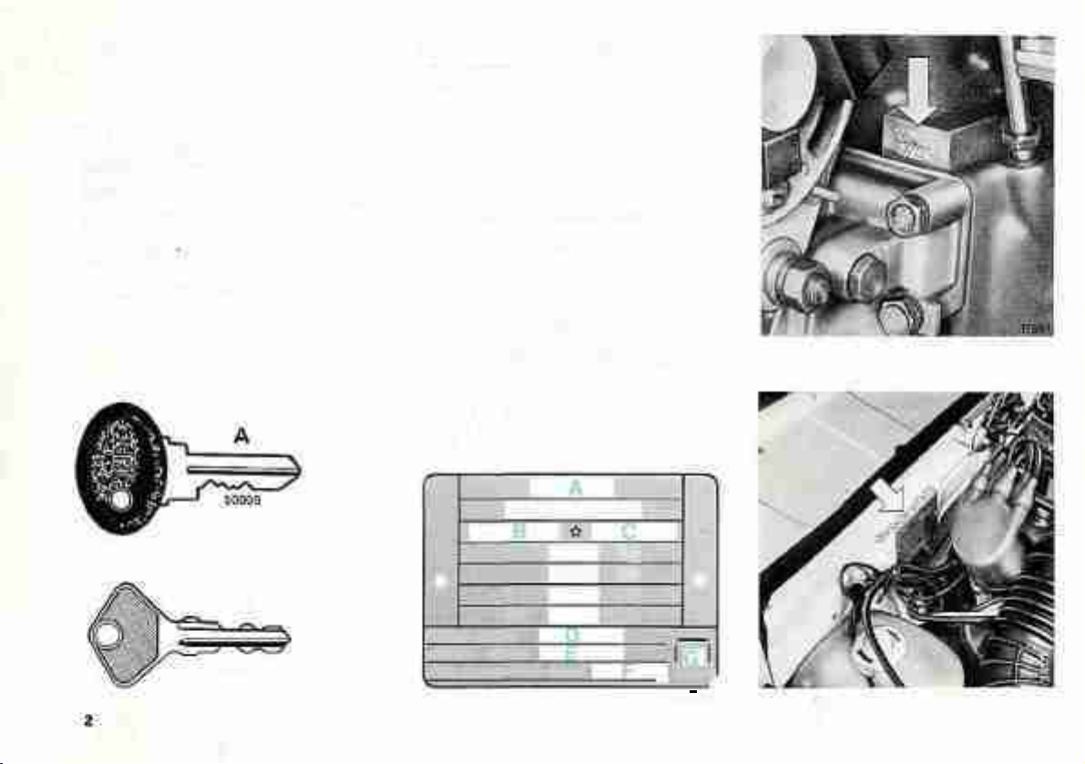
KEYS
IDENTIFICATION
DATA
Each vehicle is provided with two
keys in duplicate; quoting the number
stamped on each key is essential to
obtain a replacement from FIAT's
Sales Organization.
A For ignitron switch
B For door and trunk locks.
B
50022
• Manufacturer's Plate
A - Name of manufacturer
B - Vehicls identification code
C - Chas&is Number
D - Engine type
E - Version code
F - Number for spares
G - Space reserved for Diesel vehicles
Kg
o
MOTOFtE-ENGINE
YEFSIONF- VERSION
N'PERRICAMBI-NäFDR
1-
2-
Kg
Kg
Kg
SPAR£S
0
i i
1 1
39090
— J
Page 5

• Engine Type (132 C3.031) and
Identification Number - Punched
on crankcase, near oil filter mount.
• Chassis Type (124 CS2} and
Identification Number - Punched
on engine compartment bulkhead
(permanent structure) right side.
• F.M.V.Safety Standard 115Tag
Type of vehicle and chassis number,
located on panel top between instrument cluster and windshield.
• F.M.V.Safety Standard 110Tag
Tire data and car capacity, located
on R.H. door pillar, above striker.
• A) F.M.V. Safety Standard Conformity Tag - Month and year
of manufacture, gross vehicle weight
rating, gross axle weight rating,
chassis number and car type, located
on left door pillar.
• B) Vehicle Emission Control Information Label - Located on left
door pillar.
• E.P.A. and California Regulations Conformity Tag - Air pollution
control specifications for correct engine
tuneup and adjustments, located in
engine compartment, on cowl.
3
Page 6
1
2 3 4 5 6 7 8 9
10
11
12 13 14 15
16
35 34
33
32
31
30 27
Page 7

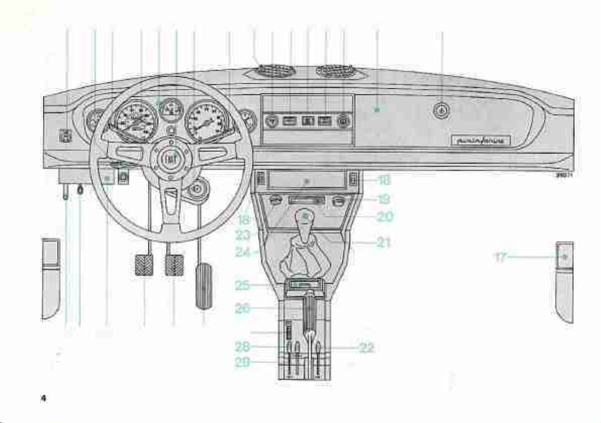
INSTRUMENTS AND CONTROLS
1 lighting switch, three-position
2 Turn signal lights switch levei
3 High/Low beams change-over
switch lever
4 Inspection lamp receptacle
5 Instrument cluster
6 Horn button
7 Steering lock ignition switch
8 Windshield washer and wiper
switch lever, three-position
9 Air outlets
10 Windshield wiper sweep rate knob
11 Low brake fluid level/hand brake
ON indicator
12 «EX. GAS SENSOR)) indicator
13 Fasten belts indicator
14 Knob switch and rheostat for
instrument cluster lighting
15 Glove compartment
16 Glove compartment lock
17 Utility recesses (two)
18 Power window switches housing
19 Courtesy light with switch
20 Vehicular hazard warning signal
indicator and switch
21 Gearshift lever
22 Lever controlling air flow through
outlets 9 and/or under dash
23 Cigar lighter
24 Optional radio housing blanking
lid
25 Ash tray
26 Hand brake lever. To release the
lever press in button on top of
handgrip
27 Two-speed heater fan switch,
three-position
28 Air volume control lever
29 Air temperature control lever
30 Accelerator pedal
31 Service brake pedal
32 Clutch pedal
33 Fusebox
34 Hood release emergency cable
35 Hood catch release lever
Page 8
FIAT Dealer for a cooling system
check (including fan circuitry).
a b
n i m n
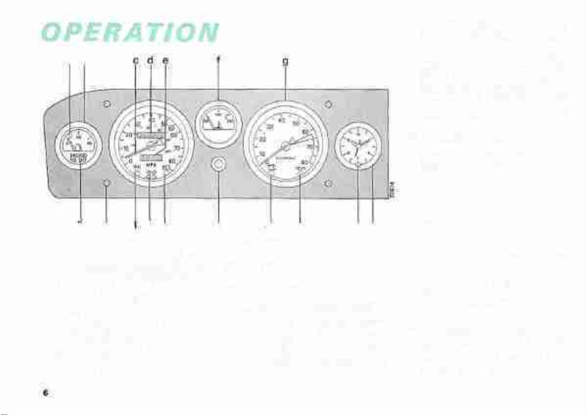
Instrument Cluster
a) Fuel Reserve Indicator (Red) -
Warning that the fuel supply available in the tank is between 5
and 7.5 liters {173to2 Gals).
b) Fuel Gage
c) Speedometer - This instrument
(which includes the odometer) is
factory-sealed: any tampering by
unauthorized persons will invalidate the warranty.
o p q f s
d) Odometer (Totalizer)
e) Trip Recorder
f) Engine Water Temperature
Gage - If the pointer enters the
red area it means that the engine is
overheating: it will then be necessary to immediately rev down the
engine to idle speed (do not $witch
off). Should the pointer remain
on the red area, contact the nearest
g) Tachometer - Electronically-op-
erated from the ignition distribu-
tor. The yellow area indicates ma-
ximum engine speed for all gears
whereas the red area shows
dangerous engineoperating speeds.
h) Type of Fuel Used (see page 33)
i) Cluster Panel Mounting Knobs
(Four)
I) Parking and Tail Lights Indi-
cator (Green)
m) Turn Signal Arrow Indicator
(Flashes green)
n) High Beams Indicator (Blue)
o) Trip Recorder Zeroing Knob -
Turn knob clockwise but never
when car is running.
p) Battery Charge Indicator (Red)
With engine inoperative, and ignition key in position MAR, the
charge indicator is on and must
go out when engine is started;
Page 9
should indicator turn on while
engine is running, this is a warn-
ing of a fault in the battery recharging system: turn immediately to a FIAT Dealer for assist-
ance.
Fasten Belts Indicator (Red) and
Buzzer - Both are operative for a
few seconds when a starting attempt
is made with seat belts (driver and/or
passenger) unfastened.
q) Insufficient Oil Pressure In-
dicator (Red) - The light should
go off when oil pressure is sufficient to ensure adequate engine
lubrication,
r) Clock Reset Knob - Push and
turn clockwise making sure that
it springs back when released.
5) Quartz Crystal Clock
Lighting Switch
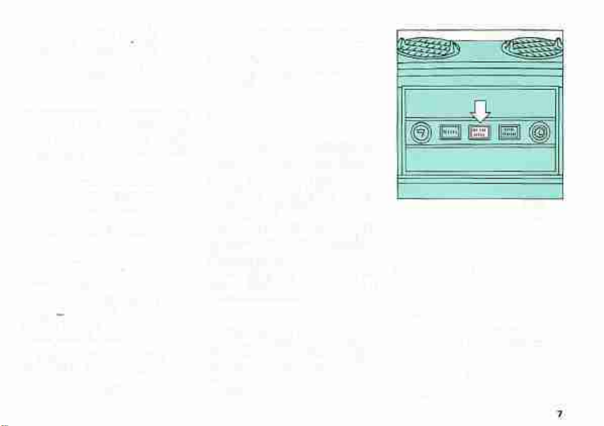
Up = All lights OFF.
With Ignition Key at MAR:
Down — Parking and tail lights,
headlight low or high beams and
flashers (main beams).
With Ignition Key Removed:
Center (night parking oniy) = Park-
ing and tail lights.
Down = All lights OFF.
Low Brake Fluid Level/Hand Brake
ON Indicator (Red)
With ignition key at MAR the indicator
lights up to warn the driver that the
bulb is efficient. In case the indicator
remains ON it means either that the
hand brake lever is pulled upwards
(brake applied) or that the brake fluid
level is too low.
Should the indicator turn on while
the vehicle is moving, stop and check
the fluid level in reservoir. If the level
is too low, great care should be taken
when applying the brakes and the
nearest FIAT Dealer contacted for a
brake system check.
Vehicular Hazard Warning Signal
Switch - Turns ON (independently of
key position in lock switch) the front
and rear turn signal lights which will all
flash simultaneously to warn of the presence of the vehicle stopped on the road.
38003
EXHAUST GAS SENSOR
INDICATOR (red)
Lights up:
— Every 30 000 miles to warn owner
of need to replace exhaust gas
sensor (Lambda probe);
— On starting; it should go out when
engine is started.
Page 10
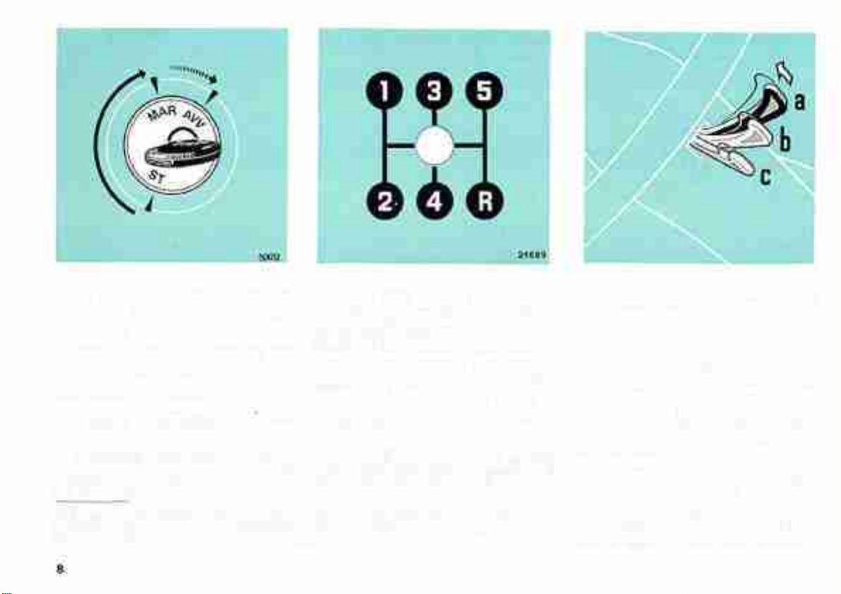
Steering Lock Ignition Switch (*)
(See page 16 for starting procedure
instructions)
MAR (Run) = Engine ignition ON and
accessories energized
Remove Key Buzzer - Operates
when the steering wheel side door is
opened to leave the car and the ignition key is forgotten in the lock switch.
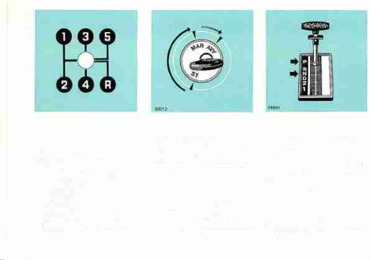
Gearshiftirtg Pattern - To engage
reverse (R), press the lever and shift
AW (Start) = Engine starting
ST [Stop) = Steering post antr-theft
lock in. Key removable
as indicated by the gating pattern.
Note: The use of fifth gear over 4B mph
improves fuel economy.
The total or partial removal oi key will lock the steering post even if car is in motion.
To facilitate the disengagement of steering post lock, slightly rock the steering wheel
while rotating the key. Key must not be left in position MAR when engine is inoperative
and must be removed only when leaving the car, especially if unattended.
(*) Even with key removed (position ST) the following circuits are stifl energized : courtesy
lights; horns; cigar lighter and housing indicator; vehicular hazard warning signal; remove
key buzzer; clock; inspection lamp receptacle.
Windshield Wiper/Washer Switch
Lever
a = Wiper off
b = Wiper On-Off intermittently (par-
ticularly useful in drizzly weather)
c = Wiper on continuously
Lifting the lever towards steering
wheel, whatever its position, will switch
on the washer.
Windshield Wiper Sweep Rate
Knob - Provides high or low sweep
rates in either wiper continuous or
intermittent operation, depending on
the position of wiper lever switch.
Page 11
25947
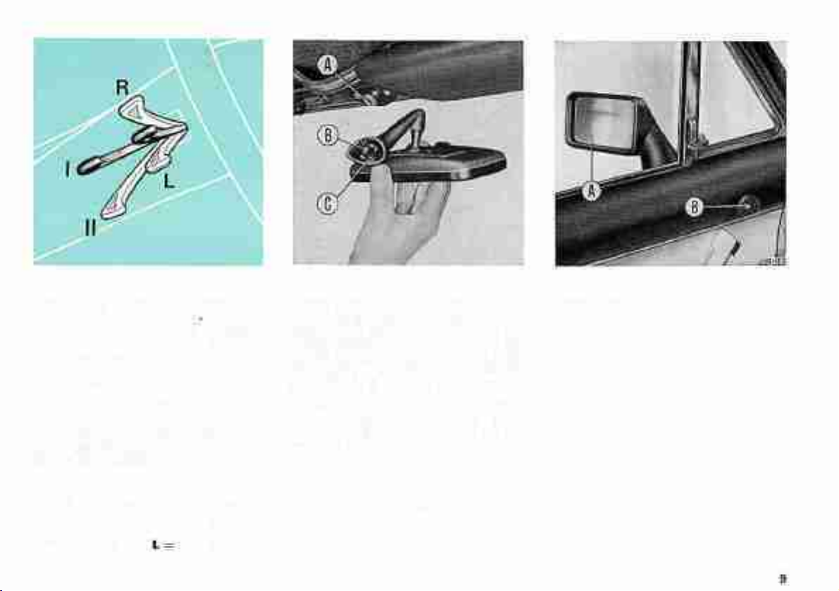
High/Low Beams Change-Over
Switch Lever {With lighting switch
down and ignition switch at MAR)
I = Low beams
II = High beams
By lifting the lever towards steering wheel headlight high beam flashes
are obtained even with all lights out
(Daylight signals).
Turn Signal Lights Switch Lever
Automatically trips back to OFF.
R = Right turn
Left turn
Inner Rear View Mirror - Collap-
sible, with anti-glare (Day/Night) po-
sition controlled by a lever. If the
mirror comes off its seat, following
an impact, refit by engaging spring B
on stud A — make sure the two
location dowels are properly registered
with relevant seats — and press
on base C. Engagement is of the
snap-on type.
Outer Rear View Mirror A on
steering wheel side door is adjustable
from driver's seat, by means of lever B.
Page 12

DOORS
Opening
From outside - Unlock and pull the
handle.
From inside - Pull up lever A.
From inside (safety latch) - With
door already shut set the lever A down.
The lever will thus first insert the
safety latch and then snap back to
rest.
SEATS
Seats may be adjusted for leg reach
after moving control lever A downwards.
Locking
From outside - Both doors are pro-
vided with key-operated locks. Step-
ping out of the car on the curb side
is thus also possible. Always use the
key; never lever A.
10
Note: Lubrication of lock cylinders is not
recommended. At most, blow some graphite powder into the cylinder keyhole.
In cold climates it is recommended to
squirt in some special antifreeze fuild for
locks. Repeat the operation every time
the car is washed or at least every 15 days,
if insertion of key in the frozen lock proves
difficult, simply warm up the key.
Once the desired position is found,
release the lever and make sure the
seat has locked.
The position of the backrest is ad-
justed by turning knob B.
Page 13

Warning
Before fastening the belts make sure
the seats and headrests are properly
positioned.
Each belt is intended for use by
one adult or one child over 6 years
of age.
For access to the rear compartment push down lever C and tilt
backrest downward.
On top of each seat backrest is fitted
a headrest: to re-set height pull up
or push down as required.
The headrest must be adjusted so
as to support the head and not the
neck of the occupant.
39078
SEAT BELTS
Seat belts provided as standard
original equipment are of the 3-point
lap type.
Pull belt fully out from retractors
without stopping as otherwise it will
be necessary to return the belt to the
stowed position to release the retractor stop mechanism.
To fasten, fit tongue A into buckle
B until a sharp click is heard.
Adjust the belt snugly around the
hips, not the waist, allowing excess
webbing to be pulled back into re-
tractor.
To free yourself from the belt
restraint: simply press in buckle
button C.
Occasionally, check that webbing
is in good condition.
In the event of an accident even
if the belt you were wearing is apparently undamaged it is suggested
that you replace it with a new belt
assembly of the same type.
To keep belts clean, wash only,
using warm water and mild soap.
Rinse and dry thoroughly. Do not
use strong detergents and avoid any
chemical that may weaken the equipment.
Users are warned to consult the
Manufacturers in case of doubt and
not to make any alterations of, or
additions to, seat belt assemblies
and/or anchorages.
11
Page 14
VENTILATION AND HEATING
Ventilation and heating are adjusta-
ble according to seasonal requirements.
To ensure best comfort to occupants it is important to become familiar
with system controls and operation.
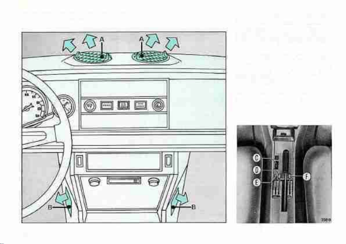
Admission of Heated or Fresh Air
Heater fan switch C is ener-
gized only when ignition key is in
position MAR.
Pressed in forward = High speed
Intermediate position = Off
Pressed in backward = Low speed
12
390 68
Page 15
Lever D controls the air tempera- Defrosting end Demisting
ture.
Pulled all back - No heating of air
Pushed allforward - Maximum heating
of afr
For quick defrosting of windshield,
pull back completely lever F, push
forward lever D and set lever E in an
intermediate position. Turn on the
heater fan by switch C.
Lever E controls the air volume.
Frost Precautions
If during cold weather the car must
remain inactive for some time at freezing temperatures and the cooling
system is not protected with antifreeze
mixture, it will be necessary while
draining the radiator and Jackets
to empty also the heater core by
shifting lever D all forward.
Pulled all back - Maximum air flow
Pushed all forward - No admission
of air
Intermediate positions are used
especially when outdoor temperature
is low to limit the flow of cold air
around heater core.
Lever F controls the amount of air
flowing through windshield outlets A
and into front lower area through
console outlets B.
Pulled all back - Air flows through
outlets A only
Pushed all forward - Air flows through
outlets A and B
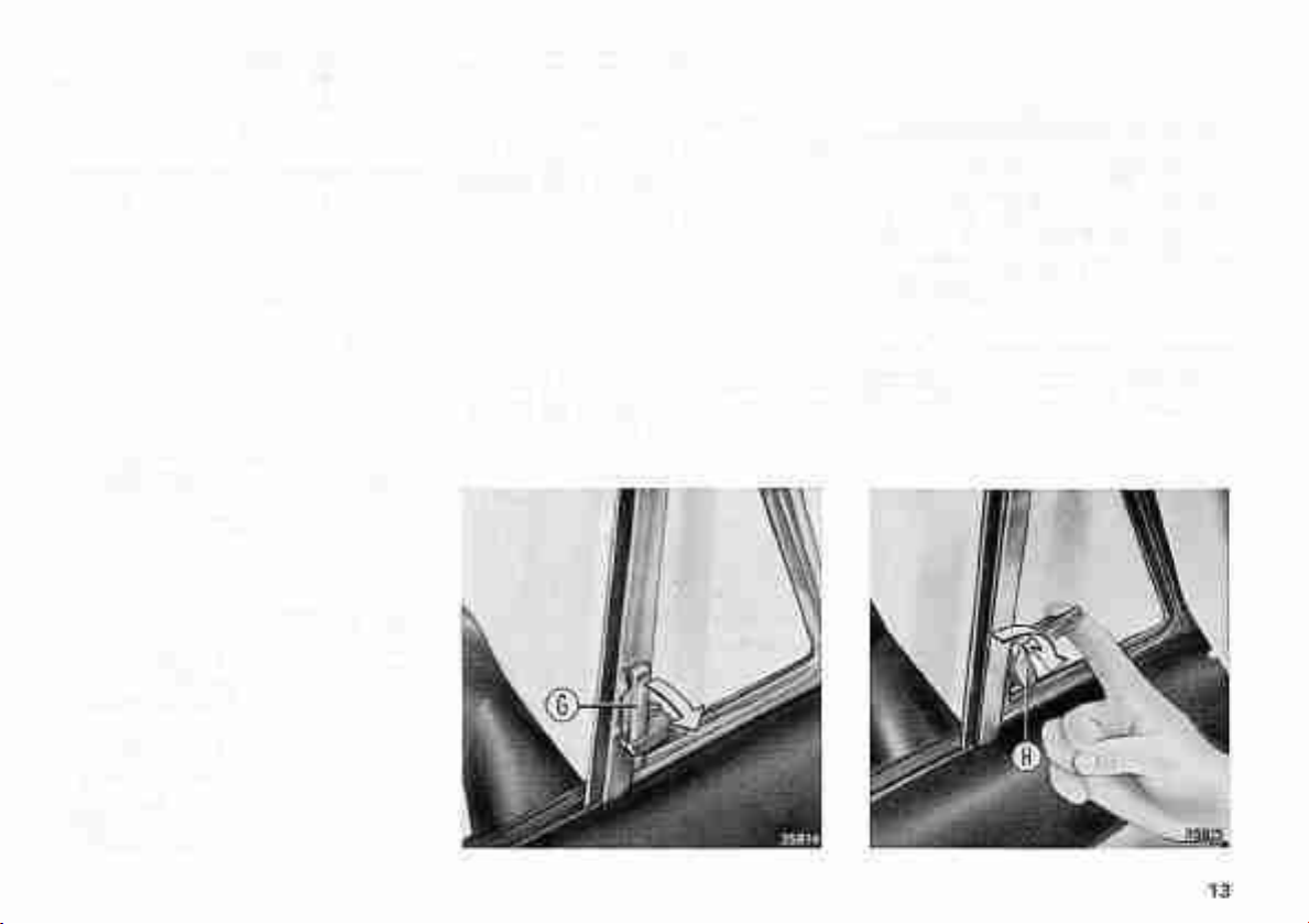
Door window ventilators are
opened by pulling lever G and tur-
ning upward lock H.
Note: If heating proves inadequate,
operation of the thermostat on the line
from cylinder block to radiator must be
checked.
Page 16
FOLD-AWAY TOP
: ti|ll
til* Bftl J.s,
*»^ *{ *rr^5^ ^^^
• ** •*&£& ^ ^JStH
1
-
-
* *
!l
r:.;
1*
> * I 1 " '" •'•' -
* *• - •
1
^^
• * * r ••
* " r "* ^ """ M * Itv
Wmgmm
^•:i •••••'•
! * i &?>*&!
J^ 1^" ^-.H
Si
14
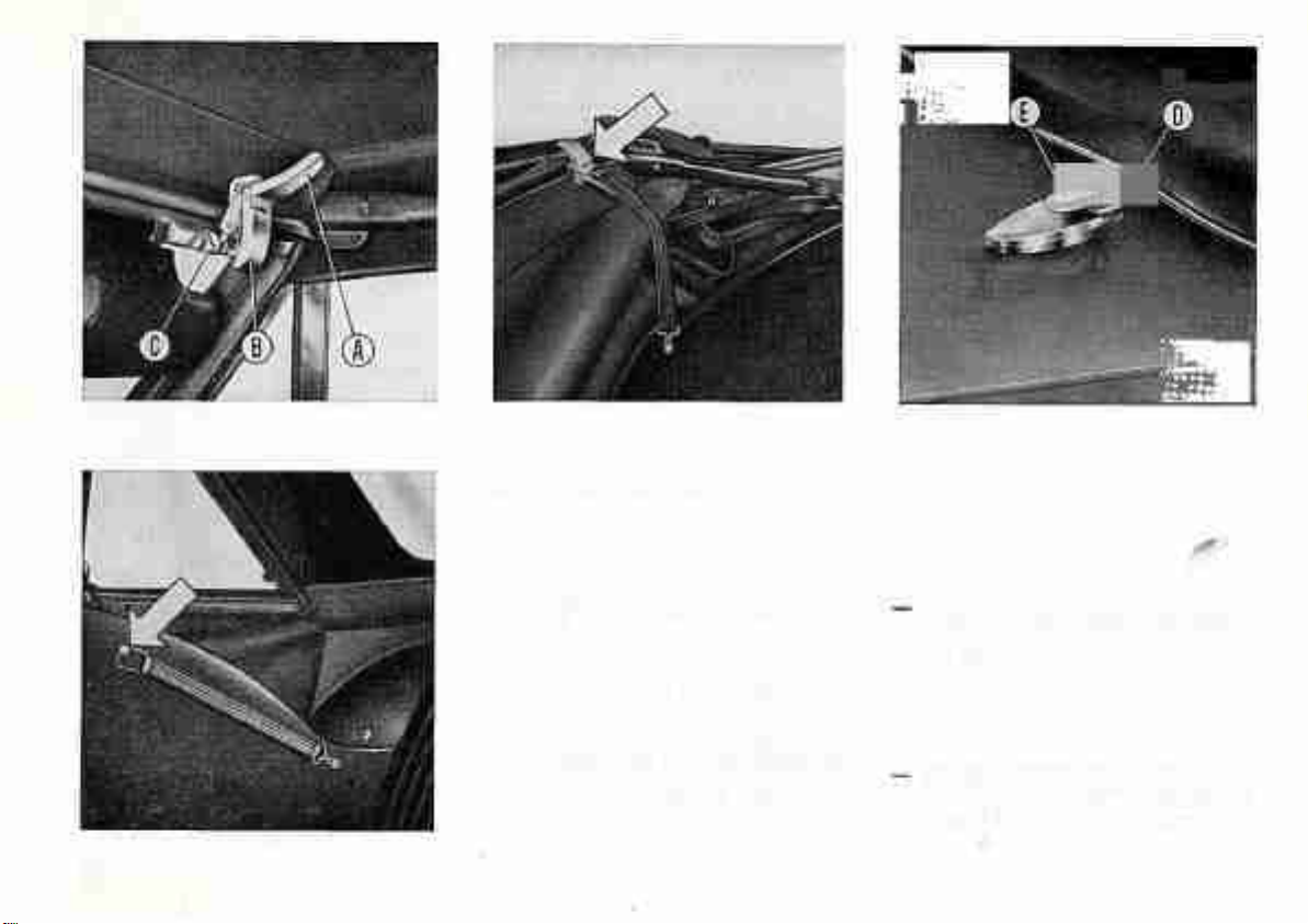
To lower the folding top, proceed as
follows:
— Wind down the door windows.
— Pull down the two latch levers A
and release clamps B from latches C
securing the top to windshield
frame.
Push the top to the rear, making
sure the back window is not pinched by the metal frame.
Free the rubber strap from the peg
on body side and strap the folded
top as shown in the figure.
Page 17
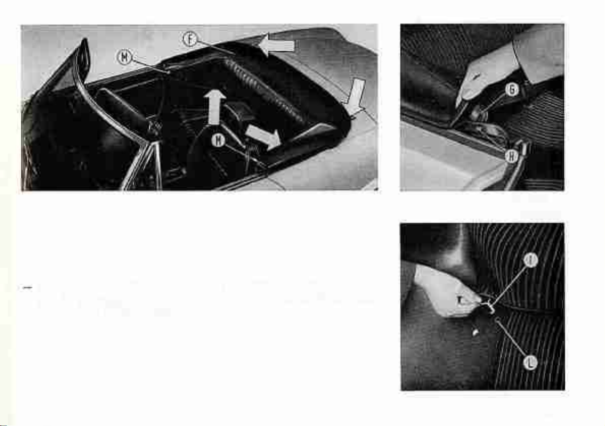
Place cover F on the folded top
well by fitting rear eyelets D on
hooks E (page 14) then catches G
in detents H, spring hooks I in
holes L and snap on the button
fasteners M.
15
Page 18
38000
STARTING THE ENGINE
Cold Starts With Manual
Transmission
— Move gearshift lever to neutral.
— Depress clutch pedal, especially in
cold climates.
— Insert and turn ignition key clock-
wise to the stop, that is position
AW. As soon as engine is started
release key which will snap back to
position MAR.
16
Should the engine fail to start
return ignition key back to ST position and repeat starting attempt.
— Do not step on accelerator pedal
until the engine is running smoothly.
— Avoid sudden acceleration when
engine is cold.
Do not continue with repeated starting attempts. If the engine fails to
start or stalls at idling have the fuel
injection and ignition systems checked
as soon as possible.
Cold Starts With Automatic
Transmission
Move the selector lever to HI or P
Engine starting is not possible with
the selector lever in any other position.
Then proceed according to manual
transmission instructions.
Hot Starts
For vehicles with manual and automatic
transmission turn ignition key without
touching accelerator pedal.
Page 19

DRIVING THE CAR
Never maintain nor exceed the
maximum allowed speeds and do
not drive with tachometer pointer
steadily on the yellow sector.
Do not travel steadily for long
intervals at top speed in any gear.
All red indicator lights should be
out while driving.
Do not coast downhill with the
clutch pedal depressed, the transmission in neutral or the engine off, as the
marginal saving in fuel consumption
which may be derived from such
practice does not compensate for the
resulting loss in brake lining life and
driving safety which is provided by the
braking effect of the engine.
Remember that upon switching off
the engine, the brake servo is
deactivated and, therefore, braking
requires more effort.
Do not allow the engine to lug,
particularly when driving up steep
hills, but shift down in good time to
benefit from maximum engine pulling
power.
Do not ride the clutch, otherwise
slippage and damage will result.
Ensure that both the foot and
hand brakes are efficient at all times.
After a car wash apply the foot-brake
a few times so as to restore full
brake effectiveness.
Always apply the foot brake progressively. Remember that wheel locking, especially with an unladen car,
will result in dangerous skidding. In
case of emergency the hand brake may
be used to stop the car.
On wet or slippery roads hard
braking will increase the likelihood of
wheel locking and consequent inevitable loss of handling control. Instead,
use the engine braking effect by
engaging a gear lower than would
normally be required. Braking, if absolutely unavoidable, should be gentle
and progressive and, in any case,
simultaneous with engine braking.
On icy roads drive slowly, turn
the steering wheel very gently, avoid
using the brakes, change gear smoothly
and do not drive with the clutch
pedal depressed. If the car starts
skidding release the accelerator pedal,
do not brake, but steer smoothly in
the direction of skid; as the car re-
gains its course straighten the wheels
and accelerate gently.
Always use tire chains or snow
tires before starting a journey on ice
or snow covered roads and remember
that while snow chains can be fitted
to the driving wheels only, studded
tires should be fitted to all wheels.
When driving in mist or fog during
daylight switch on the parking and
tail lights: do not use the high beams.
17
Page 20

Before turning or changing lanes,
in addition to giving the correct signals
glance in the mirrors to ascertain the
intentions of the drivers behind you.
Before cutting back into your lane
after overtaking a vehicle wait until
it appears in your inner mirror.
At night when meeting oncom-
ing traffic, keep your eyes on the
right side of the road rather than
looking straight into the approaching
headlights or other light sources: you
will avoid being blinded.
PARKING
Always apply the hand brake when
parking and if on a grade, for added
safety also shift into first or reverse
depending on whether the car is
heading up- or downhill.
RECOMMENDED
SHIFTING SPEEDS
1st-2nd 2nd-3rd 3rd-4th 4th-5th
15 mph 25 mph 40 mph 45 mph
Note: In any case the maximum speed
listed on page 62 should never be exceeded.
When the car is left in dark areas
always turn on the parking lights:
lighting switch pressed halfway in
at bottom.
18
Page 21
AUTOMATIC
TRANSMISSION
(Optional Extra)
OPERATION
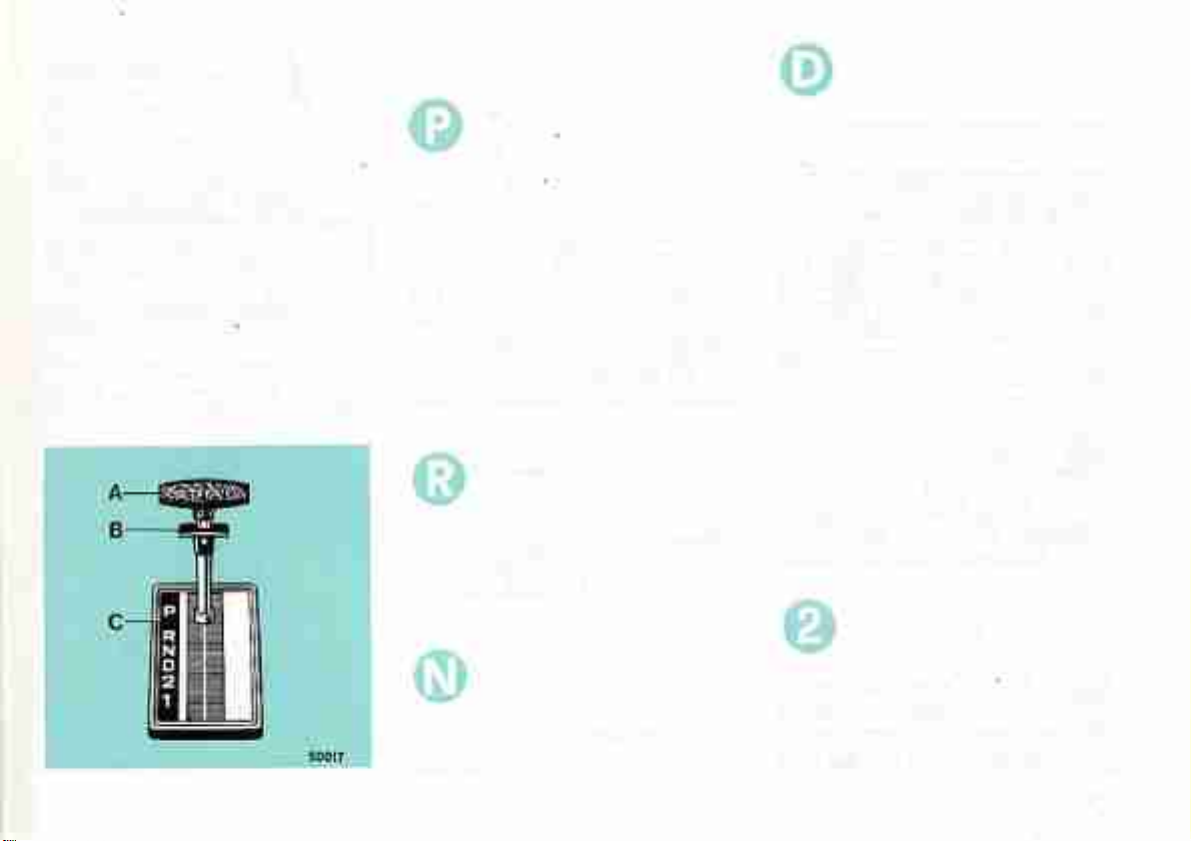
To obtain any ratio move selector
lever A to the desired position.
When shifting from P to R, R to P,
N to R, D to N or 2 to 1 lift trigger B
simultaneoulsy. When shifting from D
to 2 and viceversa do not operate
trigger B, Light C indicates the selected
position.
Selector Lever Positions
P. Park - R. Reverse - M. Neutral D. Drive - 2. Intermediate - 1. Low.
Selector Lever Positions
Park
In this position the transmission is
mechanically locked but engine starting
is possible. Park should not be selected
when the car is in motion or stationary
in busy car parks where shunting is
likely to occur.
Use of the Park position is recommended when parking on flat and
sloping ground and before servicing.
Reverse
To select Reverse bring the car to Q
dead stop and release the accelerator
pedal (engine idling).
Drive
This position is used for normal
driving.
The transmission starts in low gear
and automatically changes up or down
at suitable road speeds according to
the position of the accelerator pedal
and the demands made by the driver.
For quick down-shifting depress the
accelerator pedal through its hard spot
(kickdown position).
Kickdown permits down-shifting
from third to second below 59 to 64
mph or into first below 31 to 34 mph.
Normal change-down from D to 2
and D to 1 can be obtained by means
of the selector lever below 70 mph
and 43 mph respectively, without de-
pressing the accelerator pedal.
Intermediate
Neutral
In this position the engine can be
started.
Operation is as described under D
but no up-shift into third is possible.
This may be advantageous when driving
over hilly or difficult roads requiring
19
Page 22

consistent pull and moderate engine
braking.
Low (Lock-up in First)
o
To be selected when driving up and
down very steep hills, especially with
a trailer on tow, and when maximum
engine braking is desired.
When the selector lever is moved to
1 the transmission changes to, and
remains in first, regardless of engine
speed.
Note: With the engine idling and D,
2, 1 or R selected the car may tend to
creep forwards or backwards. This
tendency can be obviated by lightly
applying the foot brake and may well
be advantageous for difficult parking
maneuvers.
Starting
Before starting the engine move the
selector lever to l\l or P.
Engine starting is not possible with
the selector lever in any other position.
Starting instructions not described
here are as given on page 19.
Depress the brake pedal without
accelerating at all, and move the
seSector lever to 1, 2, D or R as
desired.
Release the hand brake and the foot
brake.
Depress the accelerator pedal progressively. In D the car will move off
in first gear and automatically change
up as speed is increased,
For maximum acceleration depress
the pedal through its hard spot. This
causes up-changes to occur at higher
road speeds than under part-throttle
driving {approximately 40 to 43 mph
from first to second and approximately
65 to 70 mph from second to third).
Exceptionally, when maneuvering
in confined areas or for hill-holding
the driver will find it convenient to
use the left foot on the brake pedal
and, using this pedal in conjunction
with or without the accelerator pedal,
a high degree of control is obtained.
During normal driving both the
accelerator and the brake pedals should
be operated with the right foot only.
Towing by Another Vehicle
Proving the transmission is
operating satisfactorily, the car may
be towed in N over distances up to
30 miles and at road speeds not
exceeding 30 mph, otherwise gearbox
damage may result. If the car is to
be towed over long distances, or if
the transmission is defective, the car
must be towed with the rear wheels
raised from the ground or propeller
shaft disconnected.
Warning
To prevent dangerous over-revving
do not exceed the prescribed shifting
speeds.
Stopping
To stop the car release the accele-
rator pedal and apply the brakes.
No further action is needed for
short stops, as first gear will be automatically re-engaged when moving
off again. On upgrades, hold the car
exclusively by pressing the brake pedal.
For long stops, move the selector
lever to hi and apply the handbrake.
When leaving the car unattended
shift the selector lever to P after
coming to rest. Thus, the transmission
will be locked.
20
Page 23

WHEEL CHANGING
If possible, place the car on level
ground and lock rear wheels by the
hand brake.
Release strap B and take out jack A
and spare wheel C in trunk.
38821
The jack is completed by hand
lever D and extension E,
Extension E has two drives: a hex.
shank for the jack hand lever and a
hex. socket to manipulate both the jack
and wheel bolts.
To Remove the Wheel
— Slacken about one turn the four
wheel fixing bolls using extension
E and lever D.
— Place the jack under the car at the
bracket nearest the wheel to be
removed.
— Fit extension E to jack shank, and
turn handwheel F until the jack
contacts the lift bracket under floor.
— Make sure the ground is sufficiently
hard (that is, jack base does not
sink during the lift action).
3BS24
Fit the hand lever to extension E
and actuate the lever to and fro until
the wheel is clear of the ground.
Back out completely the bolts and
remove trim and wheel.
Keep the bolts in a clean place to
prevent the threads from getting
fouled with dirt, a frequent cause
of difficulties at reassembly.
Page 24

To Fit the Wheel
— Fit the spare wheel seeing that the
location dowel fits into the location
hole in wheel disk.
— Remove the jack hand lever and
actuate handwheel F of extension
E and lower the car.
— Fully tighten the wheel bolts in
criss-cross sequence.
— Refit trim and refit and tighten
uniformly the wheel fixing bolts in
criss-cross sequence.
— Check that the newly fitted tire is
inflated to the correct pressure.
When repositioning the jack in the
trunk make sure extension E is properly
housed and Jack, bag and hand lever D
are correctly fastened by strap B.
34975
JACKING UP AND
TOWING
When either the front or rear end
of car must be raised with a garage
jack, it is necessary to fit jack head
under front suspension cross rail, in-
terposing a suitably thick (abt. 3 cm
- I'A in.) wooden block, or rear
axle bulge.
If car needs towing with a rope
this must be attached to the specially provided front brackets.
22
Page 25

MAINTENANCE
This section includes all periodical
maintenance operations essential for
continued effectiveness of the car.
The lubrication, cleaning, inspection and adjustment operations recommended in relation to given mileages
are listed on a General Maintenance
Schedule. Reference is made to the
pages where each operation is described.
The Owners Warranty and Service
Book contains a free service coupon.
This service should be performed at
1 500 miles.
Failures, other than those resulting
from defects in material or workmanship, which arise solely as a result of
owner abuse and/or lack of proper
maintenance are not covered by war-
ranty.
Particular stress is laid on
importance of reporting to a
FIAT Dealer for all the main- "
tenance operations so marked :
For oil grades not mentioned here,
seethe Fill-up Data Table.
EMISSION CONTROL
SYSTEMS
The maintenance operations necessary to ensure the proper functioning of the vehicle emission control
systems are printed in red for im-
mediate identification both in the
General Maintenance Schedule and
in the paragraphs of this section.
The engine tuneup and adjustment
specifications are also listed on the
E.P.A. and California Regulations Conformity Tag. located in the engine
compartment (see page 3).
For oil these operations it is also
recommended to refer to the instructions specified in the Owners Warranty
and Service Book,
NOTICE
Besides the routine maintenance
operations listed in the Schedule,
this section describes other operations
which must be performed only in
special cases of defective operation of
mechanical units.
23
Page 26

MAINTENANCE
GENERAL MAINTENANCE SCHEDULE
We recommend that all operations so marked be entrusted to the Fiat service network
OPERATIONS
Valve clearance: Check and adjust if necessary
Air cleaner: Renew filtering element ....
Spark plugs : Changs
See page
26
27
27
Every
15 000
miles
• *
Every
30 000
miles
0
Every
45 000
miles
Alternator and water pump drive belt; C/ieck tension and state of wear; Adjust andjor
renew as necessary
Oxygen sensor (Lambda probe): Renew , ,
28
32
o •
o
o
Brakes; Check state of wear of seals, lines and check hand brake efficiency, renew or adjust
as necessary ,
Transmission (manual and automatic) and differential: Change oil
Clutch: Check pedal height and adjust if necessary
Suspensions, steering and drive line: Check components
Wheel bearings: Check lubrication
Body: Lubricate door locks and hinges
1
These operations are not obligatory but only recommended when the car is used frequently in abnormal traffic conditions or on sandy
38
39
39
41
41
43
•
and dusty roads.
24
Page 27

SPECIAL MAINTENANCE
OPERATIONS
Engine oil -.Check level , , 26
Engine oil and filter; Change 26
Cooling system : Check coo/ant level 37
Brakes: Check brake pads and front discs 38
Automatic transmission (where fitted): Check oil level 40
Tires: Check pressure 41
Battery: Check electrolyte level, terminals and clamps 44
See page
Lubricant Designations
FIAT
VS
+
INTERNATIONAL
Single-grade low-ash content detergent oils - API Service SE, to
MIL-L.46152 and above :he CCMC
European Sequence
FIAT
Gl/A
W90/M
INTERNATIONAL
A.T.F. - DEXRON II Type
for automatic transmission
SAE 30 W/90 EP Oil to MIL-L-2105 B
Every
500
miles
(or
weekly)
0
Every
3 000
miles
•
Every
7 500
miles
ZC90
SAE SOW/90 Oil with anti-wear
additives, for manual transmission
Jotai
MR 3
Lithium-base Grease N.L.C.I. Mo. 1
Lithium-base Grease N.L.G.I. No. 3
25
Page 28

ENGINE
Engine Oil
Every 500 miles or weekly -
With engine cold, check oil level which
mus1 always be between the Min
and Max marks on dipstick, and top
up if required.
Every 7 500 miles or every six
months at most - Replace
oil with engine well warmed up.
Drain all used oil through plug B.
Oil should of course be changed
also in relation to the grade used and
outdoor temperature (Singiegrade or
Multigrade) as shown in the Fill-up
Data Table,
Engine Oil Filter
Every 7 500 miles or at every en-
gine oil renewal - Unscrew
filter A from its support on
crankcase, and replace.
Before fitting a new filter on the
support, wet its seal with engine oil.
Screw on the filler: once the seal
contacts the support, tighten 3/4 turn
more.
Tappet Clearance
Every 15 000 miles or whenever
valve operation becomes noisy.
Check clearance between tap-
pets and cams. Specified
clearance, with cold engine, is .41 10
.49 mm (.016 to .019 in) for intake
and .46 to .54 mm (.018 to .021 in)
for exhaust valves.
.
Page 29

37995
Spark P/ugs
Every 30 000 miles (*): Change
spark plugs. To disassemble
spark plugs, withdraw terminals
A and back off using a suita-
ble wrench.
New spark plugs must be of the type
specified (see page 62}; if their thermal
rating is incorrect engine malfunction
and/or failure may occur.
(*) It is recommended thai air cleaner and
spark plugs be replaced every 15 000 miles
if the vehicle is frequently driven in heavy
traffic conditions or sandy or dusty areas.
Air Cleaner
Every 30 000 miles (*) : Change fil-
tering element. To gain access
to filtering element A undo
fasteners C using a screwdriver
and remove cover B.
Change the filtering element, refit cover
and secure with fasteners C.
Reinstall fasteners by pressing on
curved section.
27
Page 30

Alternator and Water Pump
Drive Beit
Every 30 000 miles (*); Check belt
for wear and if necessary renew,
Also check belt tension and
adjust if necessary,
Belt sag should he 1 to 1.5 cm (1/3
to 1/2 in.) when firm thumb pressure
is applied. To adjust tension of belt
driving water pump A and alternator
B, slacken nuts C and D and move
alternator outwards and then retighten
the nuts.
Do not exceed the tension since this
would result in abnormal stress on the
bearings.
(') It is recommended that [hese operations
be carried out every 15,000 miles if the
vehicle is frequently driven in heavy traffic
conditions or In sandy and dusty areas.
Ignition Timing
Spark advance is set in the factory
and no further adjustment is required
during the life of the vehicle.
— For vehicles fitted with manual
transmission, engage top gear and
move vehicle until cylinder no. 1 is
in compression phase and the mark
on the crankshaft pulley is aligned
with the fixed timing mark A indicating 10u B.T.D.C.
Ignition timing:
v.);B = 5°(Adv.);C-0°(TDC)
37991 |
Ignition timing must be checked only if
the ignition distributor is removed.
To adjust proceed as follows:
Page 31

For vehicles fitted with automatic transmission use a suitable wrench to adjust
the nut D securing crankshaft pulley
until above conditions are obtained.
— Remove distributor cap and turn
shaft manually until rotor is posi-
tioned against contact for firing of
cylinder no. 1.
Without moving distributor shaft, insert
distributor1 in its seat and secure.
Connect leads going to coit, install
cap and check that the leads are
correctly connected to spark plugs,
Connect the rev counter and the stroboscopic lamp to the engine using
spark plug lead for cylinder no. 1.
EMISSION CONTROL
SYSTEMS
Vehicle emissions are controlled by
various devices that make up the crankcase emission control system, the
exhaust emission control system and
the fuel evaporative emission control
system.
38113
— Start engine and check ignition
timing with the stroboscopic lamp.
Ignition timing should be 10"
B.T.D.C. at 800 to 850 rpm for
vehicles with manual transmission
and 10" B.T.D.C. at 700 to 750 rpm
for vehicles with automatic transmission,
— If distributor calibration is not cor-
rect, slacken and rotate manually
until correct calibration is obtained,
then tighten it.
If distributor removal is not required,
proceed from this point.
Any modification of the emission control systems is subject to federal laws
and regulations and may incur penalties.
29
Page 32

Crankcase Emission Control
System
This is a closed system designed to
prevent any emission of blow-by gases
and oil vapours into the atmosphere.
These gases and vapours are piped
to an orifice downstream of the throt-
tle and are then drawn into the engine
In any rpm condition.
1. Emission feedback port
2. Throttle valve
3. Flame trap
4. Intake manifold
5. Sump-to-air cleaner line
6. Cyclone liquid/vapor separator
7. Oil drain line into sump
38004
30
Page 33

Fuel Evaporative Emission
Control System
The fuel evaporative emission control
system is designed to prevent air pol-
lution caused by evaporative tosses
from the fuel system.
This is accomplished by a proper sys-
tem which prevents the release into the
atmosphere of fuel vapors from the
fuel tank.
The fuel vapors from the fuel lank ftow
into the activated charcoal carbon canister where they are absorbed and
stored when the engine is not opera-
ting.
When the engine is running, the fuel
vapors retained in carbon canister are
purged through a line which conveys
them to intake manifold.
The system consists essentially of:
— Sealed filler cap.
— Limited-filling tank,
— Vapor-liquid separator.
— Two-way valve.
— Vapor vent line.
— Carbon canister.
— Purge line.
39069
1. Fuel pressure regulator - 2. Cold start solenoid injector - 3. Solenoid injectors -
4. Activated carbon canister - S. Two-way valve - 6. Fuel tank vapor vent fine - 7. Fuel
return line - 8. Fuel delivery line - 3. Fuel filter - 10. Electric fuel pump - 11. Sealed filler
cap - 12. Vapor-liquid separator.
31
Page 34

Ftief Injection System
General
This is an electronically controlled
intermittent low pressure injection
system.
The fuel is injected upstream of the
intake vaives by means of solenoid
injectors supplied at constant pressure.
Flow is controlled by means of varia-
tion in the opening time of the injectors.
The main factor controlling flow is
the direct measurement of drawn air
by a special sending unit which trans-
mits the most important information
for fuel metering to the electronic
control unit.
The system is also provided with a
certain number of measuring sensors
which provide the electronic control
unit with the information required to
optimize the composition of the mixture in all engine operating conditions.
Exhaust Gas Emission Control
System
For the control of exhaust gas emissions, the injection system is fitted with
an oxygen sensor {Lambda probe)
which measures the oxygen content of
the exhaust gases and transmits any
adjustment of the air-fuel mixture to
the control unit. It is thus possible
with the aid of a catalytic converter
fitted to the exhaust pipe, to reduce to
a minimum the harmful residues con-
tained in the exhaust gases.
Oxygen Sensor {Lambda probe)
Every 30,000 miles: Renew oxygen
sensor. An indicator on the
instrument panel lights up on
completion of 30,000 miles
(see page 7) signifying that the sen-
sor must be replaced.
To renew sensor proceed as follows:
— Disconnect probe cable A.
— Back off probe B from its seat C
on exhaust manifold.
— Fi 1 new probe lubricating threaded
part with anti-seize, ami-rust grease.
— Reconnect cable A.
— Press button to zero indicator.
I79H9
32
Page 35

ELECTRONIC FUEL
INJECTION DIAGRAM
1. Battery
2. Relay set - Operates electronic
control unit 3 and motor driven fuel
pump 1 7.
3. Electronic control unit
Receives information about oil quantity, coolant temperature and temperature of cylinder head, position of
throttle valve, starting phase as well
as engine rpm and injection point.
it processes this information and trans-
mits electric pulses to the solenoid
injector.
It is connGcted with the individual
components by means of a multiple
connection plug and associated con-
necting cables.
18
Vacuum
Components con rlHttiO nS
•Systam components
3800S
4. Coil
In addition to its normal function, it
transmits the number of engine rpm or
the injection point to the control unit.
33
Page 36

5. Air measuring instrument
This supplies information to electronic
control unit of quantity of air drawn
and activates fuel supply pump,
12. Fuel pressure regulator
Keeps fuel pressure constant in fuel
lines.
20. Catalytic converter
Reduces harmful residues contained
in exhaust gases to a minimum.
6. Supplementary air valve
Supplies extra air during engine heating stage, depending on temperature
level.
7. Throttle switch
Signals idle and full load to electronic
control unit.
8. Temperature sensor
Signals coolant temperature at the cy-
linder head outlet
9. Cold starting solenoid injector
During starting in low temperatures,
injects extra fuel into intake line.
10. Solenoid injectors
Inject fuel in intake port of cylinders.
11. Delay thermal switch
This automatically controls injection
of cold starting solenoid injector.
13. Fuel delivery line
14. Excess fuel exhaust line
15. Ignition switch
16. Fuel filter
Is fitted on fuel supply line for fuel
filtering.
17. Motor driven fuel supply
pump
Delivers a constant supply of fuel to
solenoid injector.
18. Fuel tank
19. Oxygen sensor {Lambda probe).
Measures the oxygen content of exhaust gases and transmits any adjustment of air-fuel mixture to control unit.
Note: You are advised to take the
following precautions:
— Never start the engine if the battery
is not properly connected.
— Do not use charger with battery
leads disconnected.
— Never disconnect battery leads with
the engine running.
— When charging battery, disconnect
clamps.
— If temperature is above 80° C
(special body work) disconnect
electronic control unit from vehicle.
— Never remove or insert control unit
harness connector with ignition
switched on.
— Jf car is to remain out of service for
some time, add 10% of engine oil to
the fuel tank.
Page 37

Idling Speed
Any adjustment to idling speed must
be carried out with a warm engine
and with gearshift lever in neutral
position for mechanical versions and
in D (drive) position for automatic
versions.
idling speed is S50 _L 50 rpm for
manual transmission and 750 ± 50 rpm
for automatic transmission.
WARNING
Fuel Refilling
Strictly adhere to the label on instrument panel and on filler cap.
The engine is warm when the radiator
electric cooling fan has been activated
at least twice.
To adjust idle the electric fan must be
off.
To adjust, turn bypass screw A.
Idle CO Setting
The idle co setting is factory adjusted
and sealed. No additional adjustment
is required when tuning up engine
during the useful life of the vehicle.
UNLEADED FUEL ONLY
Leaded fuel will damage the catalytic
converter beyond repair, Alwais refill
at Service Stations which carry unleaded fuel (small pump nozzle).
35
Page 38

COOLING SYSTEM
Coolant Circuit
Every 500 miles or weekly - Check
the coolant level in system expansion
tank, with cold engine: the level must
3lways be abt. 7 cm (2y.F in) above the
M!N mark on tank.
When engine is very hot the level
might rise noticeably: this could afso
happen immediately after stopping the
engine.
Should the coolant level drop below
the tank MIN mark, top up by removing
expansion tank cap and pouring in
coolant, seeing that its level is as
specified.
Warning: Do not remove radiator or
expansion tank caps on a hot engine
to avoid possibly scorching your hands;
wait until engine has cooled down.
Do not top up a hot engine with
cold water.
Should more than 2 consecutive top-ups be required at
short intervals, or after limited
mileages (500 miles), the system needs
checking, This applies also when
water temperature gage pointer stays
on the red sector (see page 6).
To drain cooling system, move
lever D to the left {see page 12),
open the cocks on radiator lower side
and on cylinder block, and disconnect
expansion tank hose.
To fill the system:
— Connect expansion tank hose, close
radiator cock and remove plug A.
— Pour in water siowly through radia-
tor filler port until water overflows,
then refill the expansion tank.
— Refit radiator and expansion tank
caps and plug A then run the
engfne so as to favor a thorough
mixing of the fluid in the system.
— Stop the engine, slacken plug A,
wait for a proper system bleeding
and refit the plug.
— With engine cold check the level
in expansion tank and, if nee. top up.
Antifreeze Mixture
The cooling system is filled with an
antifreeze mixture effective down to
— 35 "C (—32
(1
F). In case of coolant
change or topping-up FIAT recommends the use of a 50-50 mixture of
water and Paraflu 11 fluid {or equi-
valent), which allows the use of hard
or chlorinated water and incorporates
Page 39

oxidation, corrosion, foam and scale
inhibiting properties and is effective
down to — 35"C (—32° F). See Fill-up
Data Table.
This mixture shall subsequently be
replaced after 45 000 miles or every
two years, whichever occurs first
thus reducing the need for any servicing action on the cooling system.
Fluid Reservoir
The « Low Brake Fluid Level » indicator (see page 7), controlled by
a float and switch assembly on brake
fluid reservoir, warns the driver of a
sudden drop in brake fluid.
Every 15 000 miles - Top up brake
fluid reservoir. Use exclusively DOT 3
MotorVehicle Brake Fluid (conforming
to F.M.V.S.S. No. 116). Avoid using
any other type of fluid which would
damage the special rubber parts in the
system.
When this mixture is used, plain
water may be added only in emergencies (sudden heavy coolant losses).
As soon as possible repair the
fault and refill the system
with the recommended coolant.
BRAKES
Brake system with front and rear
independent circuits.
If pedal free travel has become
excessive, if braking unbalance
on one wheel is appreciable
or if pedal sponginess is felt with
consequent reduced brake effectiveness, a complete inspection of the
system is needed.
A - Front brake fluid section
B - Rear brake fluid section
Front Brakes
Every 7 500 miles - Check that brake
linings are not worn down to less than
1.5 mm (.06 in). Replace if required.
Lines and Fittings
Every 15 000 miles - Check hoses
and fittings for leakages and tightness.
Bleeding
Bleeding is a delicate operation
requiring the necessary know-
how and should only be needed
when air has entered either one or
both brake circuits (line disconnection,
37
Page 40

fluid drainage, etc.). This is indicated
through pedal sponginess and reduced
braking effectiveness.
POWER TRAIN
Clutch
Manual Transmission OH
Every 30 000 miles
Hand Brake
Every 15 000 miles or sooner if
hand lever stroke is excessively
long, pull up the lever three
notches and adjust through
the appropriate tensioner (see fi-
gure below).
Then release the lever and check
that the wheels are not locked.
The clutch is mechanically controlled,
with automatic wear take up and no
pedal free travel.
Every 15 000 miles
Check pedal height and adjust
if necessary.
After repeated adjustments, check
clutch facings for excessive wear:
replace if required.
Renew oil. Let drip thoroughly
from plug B before refilling. The correct
level is up to the opening of filter
plug A.
sk is
38
Page 41

Automatic Transmission
(Where fitted)
If defective transmission operation is detected contact your
nearest FIAT Dealer.
Every 3 000 miles
Check the fluid level. Correct level
is between the MIN and MAX marks
on dipstick A.
Before checking the fluid level
drive about 6 miles to reach normal
operating temperature, stop the car
on level ground but keep the engine
running at idling speed, and move the
gear selector lever to P or N.
If necessary, top up to the MAX
mark through filler B using Fiat GI/A
or equivalent grade of automatic trans-
mission fluid. Do not overfill.
The utmost care should be taken
to ensure that both the containers and
the funnel used for topping up are
absolutely clean.
Following emergency topping-up
after a sudden leak, owners are
recommended to contact the nearest
FIAT Dealer for a general inspection
of the transmission.
mm
m
Every 30 000 miles or two years -
Renew the fluid with a warm transmission. If the fluid is found to be
heavily soiled, also renew the filter in
the valve assembly, together with the
associated seal.
To renew the fuild remove plug A.
To renew the filter remove sump B.
Axle Oil
Every 30 000 miles
Renew oil after thorough draining
through plug B. The correct level is
up to the opening of filler plug A.
MIIS Hii
Page 42

SUSPENSIONS
AND STEERING
Front Suspension [Steering
Articulation Boots and Caps
Every 15 000 miles or whenever
underbody inspections are carried out,
check the condition of ball joint rubber
caps and steering gear rack rubber
boots.
If they are damaged, replace.
The new caps should be packed
with grassofiat MR 3 prior
to their installation.
At the same time inspect ball joints
for excessive play. If evidence of
looseness exists, replace the bail joint.
Proper joint maintenance is essen-
tial for car safety.
Front and Rear Suspensions
Check rubber mounts for proper
efficiency.
Front Wheel Bearings
Every 30 000 miles - Check bearings
for play and adequate lubrication. Adjust and lubricate
with grassofiat MR 3, if nee-
ded.
TIRES
Every 500 miles or weekly - Check
pressure with a gage not forgetting
the spare wheel (see page 56 for
pressures}.
Make sure pressure is exactly the
same in each pair of tires. In hot climates, do not reduce pressure as this
would only increase tire temperature.
MISCELLANEA
Windshield Washer
Every 7 500 miles approximately
Check level in the bottle located
in left headlamp compartment.
In case of incorrect jet aiming:
Clean the jet squirt hole accurately (by
a needle).
Page 43

Check also electric pump terminals.
To re-aim jets: Turn the complete
body with a screwdriver and then the
lateral pin so as to direct the water
squirt to top of wiper sweep arc.
Windshield Wiper
Every 7 500 miles approximately
Check for proper efficiency.
To remove a wiper blade, tilt out
the arm, free blade mount A from its
lock dowel B on arm and extract the
blade upwards.
2546Q
Note - When adjusting wiper arms
position on windshield ensure that
the distance from windshield base to
wiper arm fulcrum is:
driver's side = 55 to 75 mm
passenger's side = 70 to 90 mm
BODY
Every 15 000 miles
Lubricate the following items as
required using the recommended products:
Door lock cylinders with gfaphite
powder.
Door locks through the specially
provided hole (near lock) blanked
by a plastic plug, door hinges and
limiter, and front seat reclinable
backrest control with engine oil.
Window venti-pane joints and hinges with glycerine (2-door version).
Trunk lids and engine hood catches
and hinges with petroleum jelly.
Seat guide rails with grassofiat
Jotai.
Tool Kit
The tool box contains:
Wrench, socket, spark plugs
Wrench, double end, 8x10 mm
Wrench, double end, 13x17 mm
Screwdriver, double-tipped
Punch, straight
Wrench, wheel bolts
The jack is stored in trunk, on righthand side.
41
Page 44

Exterior Body Care
the paintwork extra protection. Also
remove any stain promptly.
interior Body Care
Wash the bodywork frequently with
cold or lukewarm water. Sponge down
using a good quality car shampoo -
Deterlux or equivalent. Never use
household soap or detergent, otherwise
the paintwork may be adversely affected.
If a hose is used avoid directing it
at full force against the body. Rinse
thoroughly and dry off with a clean
chamois leather.
Do not wash your car in the
sunshine, especially in hot climates or
when the hood is still hot.
When cleaning the windshield raise
the wipers clear, and do not force them
sideways.
An occasional light polish with an
approved silicone car polish will give
Grease and tar should be removed
using a clean and soft kerosene- or
gasoline-moistened cloth. Subsequently, apply a fresh coat of polish.
To clean the windows use a good
quality spray type window polish DP 1 or equivalent - and wipe dry with
water-absorbing paper.
Chromium-plate and any other
bright decorative metal parts are best
cleaned with either cold or tepid water,
or any reputable make of car chrome
cleaner.
To preserve the rubber seals of
doors, hood and trunks use silicone
grease. This will also prevent squeaking,
particularly during the cold season.
Dust the interior, preferably using a
vacuum cleaner.
To remove grease spots from cloth
lining use a good brand of stain
remover (petroleum ether or light gasoline) apply talc liberally, allow to soak
and brush off.
To remove dirt from the seats or any
other imitation leather-lined part use a
damp sponge and a neutral or bland
soap. Subsequently, rinse with a ciean
damp sponge and dry off using
chamois leather.
Textile fiber mats should be cleaned
using a moistened cloth with good
quality detergent.
Rubber mats or floor lining should
be washed with a damp sponge and
neutral detergent or water and soap.
42
Page 45

PROLONGED INACTIVITY
If the car is to remain inactive over
long periods it is advisable to carry
out the following operations:
— Store the car in a covered, dry and
ventilated place.
— Ensure that the handbrake is re-
leased.
— Do not empty the cooling system:
in cold climates, if necessary,
replace the coolant with a reliable
high grade anti-freeze mixture.
— Remove the wiper blades to pre-
vent the rubber from distorting.
— Protect the car using a non-plastics
car cover.
If the car is to be left in the open
spray the underside and the entire
engine compartment with an approved
engine preservant, PROT V or equivalent. Do not spray a hot engine.
Before starting a sprayed engine
open the hood and wait for at least
ten minutes.
ELECTRICAL SYSTEM
Battery
Located in trunk.
Every 3 000 miles or monthly With battery at rest and cold, check
the electrolyte level.
In hot climates, check the level
more often.
When liquid additions are needed,
add distilled water (battery cold), never
electrolyte fluid (which contains sulphuric acid) as only water evaporates
from the battery in service, never
the acid.
— Check the tire inflation pressures
periodically.
— Re-charge the battery about every
six weeks.
— Switch off any electrical loads and
remove the ignition key.
— Protect the finish with a coat of
good silicone wax.
— Coat all bright metal parts with a
reputable make of car chrome
preservant.
Prior to using the car following a
prolonged period of inactivity perform
the following operations:
— Remove the chrome preservant from
all bright metal parts.
— Wash the car.
— Renew the engine oil.
— Recharge the battery,
— Refit the wiper blades.
— Check the tire inflation pressures
(including that of the spare wheel).
43
Page 46

WARNING - The battery contains
sulphuric acid. Avoid contactwithskrn,
eyes or clothing.
Externalantidote: Flush with water.
Internal antidote: Drink large quan-
tities of water or milk.
Follow with milk of magnesia,
beaten egg or veg. oil.
Call physician immediately.
Eyes: Flush with water for 15
minutes and get prompt medical atten-
tion.
Batteries produce explosive gases.
Keep sparks, flame, cigarettes away.
Ventilate when charging or using
in enclosed space.
Always shield eyes when working
near batteries.
Every 3 000 miles
Check posts and clamps for tight-
ness and cleanliness.
Except in particular service condi-
tions the battery does not require any
periodical recharge.
As your car is fitted with electronic devices
never run the engine - even for a very
short while - with battery disconnected
from the alternator or wrongly connected
(positive ground) otherwise serious da-
mage will result.
Fuses
Nine 8-Amp. and three 16-Amp.
fuses in a box under dash, driver's
side, and two 8-Amp. and 16-Amp.
fuses in separate holders.
Before replacing a blown fuse trace
the cause and remedy accordingly.
Unprotected Circuits
Alternator, starting and starter refay,
ignition high beams relay coilr battery
charge indicator, radio set {where
fitted), electronic fuel injection system.
Keep out of reach of children.
44
Page 47

Protected Circuits
•
A (8 Amps)
Turn signal lamps and indicator
Stop lamps
OH pressure gage and insufficient pres-
sure Indicator
Engine coolant temperature gage
Fuel gage, with reserve indicator
Engine tachometer
Low brake fluid level and hand brake
ON indicator
Back-up lamps
Fast idle electrovalve
Fasten belts indicator and relay for
buzzer
Delay circuit for fasten seat belts indi-
cator and buzzer
Selected gear indicator light (autom.
transmission)
30 000 miles pick-up and indicator
B (8 Amps)
Windshield wiper motor
Heater fan motor
Windshield washer pump
Windshield wiper sweep rate rheostat
C (8 Amps)
Left headlight high beams
High beam indicator
D (8 Amps)
Right headlight high beams
E (8 Amps)
Left headlight low beam
F (8 Amps)
Right headlight iow beam
G (8 Amps)
Front right parking lamp
Rear left tail lamp
Front right/rear left side marker lamps
License plate lamp (right)
H {8 Amps)
Front left parking lamp
Parking and tail lamps indicator
Rear right tail lamp
Front left/rear right side marker lamps
License plate lamp (left)
Cigar lighter housing indicator
Trunk light
Instrument cluster light
Ideogram illumination optical fibers
light source
Vehicular hazard warning signal switch
light
I (8 Amps)
Quartz crystal clock
Courtesy light
Hazard warning flasher and indicator
Inspection lamp receptacle
Remove key and fasten belts buzzer
L (16 Amps)
Horns
Engine fan motor
Wl (16 Amps)
Power window motor {Left-if fitted)
N (16 Amps)
Power window motor (Right - if fitted)
In separate holder (8 Amps)
Cigar lighter
In separate holder (16 Amps}
Fuel pump
Supplementary air valve
45
Page 48

Lights
Headlights
Alignment
For aiming the headlights,
screw 6 (vertically) and C
(horizontally) are readily acces-
sible after removing retaining
ring G.
Removal
Turn off screw E and remove
retaining ring 6. Slacken 4
screws Dand,byturning counterclockwise remove headlight unit
L. Then pull off terminal socket I.
Caution: Replace blown bulbs
exclusively with bulbs of the same
type and wattage. Weaker bulbs
will diminish visibility whereas
stronger bulbs will draw a greater
amount of current and overwork
the alternator, resulting in progressi-
ve battery discharge. For bulb specifications see page 63.
Installation
Center headlight unit L on body
by aligning locating dowel H with its
seat. Turn the unit clockwise and tighten screws D. Refit retaining ring G
by tightening screw E in hole F.
Front Parking and Turn Signal
Lamps
A Lens mounting screws
B Lens
C Bayonet-coupled bulb, double fila-
ment
D Positioning tabs
46
Page 49

Rear Turn Signal, Stop
and Back-up Lamps
The bulbs are accessible from inside
trunk after removing panel A.
To remove the panel free it from
the arrowed lugs.
The bulbs are of the bayonet type. Side Marker Lamps
B Turn signal light
C Stop light
D Tail light
E Back up light
The rear bulb holders are accessible
from inside the trunk.
To remove the bulb, disconnect bulb
holder A from seat B by turning coun-
terclockwise.
Bulb C is of the plug-in type.
822
47
Page 50

Front bulbs are accessible from in-
side fenders.
Courtesy Lamp
License Plate Lamps
To remove or refit follow the proce-
dure given for the rear bulbs.
A Spring plates (two) unit mounting
B Switch
C Bulb, pressure mounted
D Lens and body unit
To withdraw bulb holder remove retaining nuts from inside the trunk.
A Body retaining screws
B Body and lens
C Bulb holder
D Bayonet-coupled bulb
E Gasket
43
1^824
Page 51

Advice
for bodywork
maintenance
Page 52

Protection from Atmospheric Agents
FIAT has introduced a series of measures to protect the automobile from the various factors that can cause damage and
corrosion.
Briefly summarized, these factors are:
— Atmospheric pollution (urban environments and industrial
zones)
— Airborne salts (marine areas, particularly those with warm
and humid climates)
— Seasonal and ambiental humidity conditions (use of salt on
roads during the winter).
The paintwork and body shell underside can be subjected not
only to the chemical action caused by the factors mentioned
above, but also to the abrasive actron of airborne dust and
sand, mud, and loose gravel thrown up by passing cars as well
as the damaging action of salt spread on the roads in winter.
FIAT's answer to this problem can be summarized as follows:
— Corrosion and abrasion resistant paints and painting
systems.
— Widespread use of pre-treated and highly corrosion resistant
sheet metal.
— Spraying of the underside of the floor plan, engine compart-
ment, wheel boxes, and the various box sections with highly
adhesive protective waxes.
— Adequate covering or protective spraying with setting plastic
of such particularly exposed parts as the door sill panels,
wing interiors, borders, and so on.
— Use of enamels with greater resistance to polluted and
industrial atmospheres.
50
Page 53

Obviously the factors we have described act in different ways
in different cases, according to the environmental conditions
and the use of the car. Equally obvious is the fact that the
owner who cares about hfs car and maintains it properly can
make it last longer. We would like to list a few useful hints and
pieces of advice which, though obvious, often pass unobserved
for that very reason. The FIAT Service Network will be happy
to supply more details on request.
Body Paintwork
Needless to say, the paintwork does not serve only an aesthetic
function, but also covers and protects the metal on which it is
deposited.
Therefore, any abrasion or deep scratches that expose the
sheet metal should be retouched immediately to avoid pitting
by rust.
This retouching should always be done with original products
(see paint indentification plate).
Washing the car is the greater part of normal paint maintenance.
The frequency or washing depends not only on the frequency
of use, but also on the nature of the car's surroundings: washing
should be more frequent in more polluted areas, or if the car
is often parked under trees which produce harmful resins.
A correct wash should be done as follows: First the car should
be wet down with water at low pressure and sponged down
with a light (2 - 4%) detergent solution. Rinse the sponge frequently. Rinse the car with a spray of water to carry away the
loosened dirt, then dry with an air jet or chamois leather.
51
Page 54

Be particularly careful to dry the less visible areas, such as the
door frames, hood and headlight housings, where standing
water can collect more easily. Similarly, avoid putting the car
in a closed space immediately after washing, so that air circulation can help evaporate any trapped water.
Do not wash the car after it has been parked in the sun, or if
the hood is still hot, as this could adversely affect the brilliancy
of the paint.
The occasional use of a silicone car wax wilt give the paintwork extra protection and keep it shiny. If the paintwork beco-
mes cloudy due to smog accumulation, a slightly abrasive light
wax polish can be used.
Body Underside
The less accessible areas of the underside and frame box
sections have already been treated to ensure longer duration.
Regular check-ups should be made on the car. The aim of these
is to survey the soundness of the body and mechanical components, as well as to repair any damage. Particular attention
should be paid during check-ups to the drainage holes in the
underbody box frames and door frame undersides. These holes
serve to drain any water that may accumulate while driving the
car in the rain or while washing it, and so should be kept clear.
52
Page 55

In harsh environmental conditions, periodic supplementary pro-
tective treatments to the box sections and door interiors are
recommended.
These treatments must be done with special products and
techniques, and so should be left to experts. It should be done
at least every two years, and, in more severe cases, annually,
preferably at the beginning of winter.
Car Interior
The maintenance of the passenger compartment is no less important than that of the exterior. The same care should be
devoted to it.
Check to see that there is no standing water under the mats or
floor lining, as this could cause rusting. Dust the seats and
cloth parts with a brush or vacuum cleaner.
To remove grease spots use petroleum ether or light gasoline,
apply talc and brush off.
To clean seats in imitation leather, use a damp sponge and a
neutral or bland soap. Rinse several times with a clean damp
sponge.
While cleaning perforated seat covers, be particularly careful
that water does not seep through the holes to the padding.
53
Page 56

Windows
To ensure perfect visibility, windows should be cleaned with a
good quality glass cleaner and then wiped dry. Always use a
clean cloth to avoid scratching the glass.
To clean the inside of the windshield, where more obstinate
grease deposits are to be found, use sulphur ether as a solvent.
The inside of the rear window can be cleaned in the same way,
but particular care should be used to avoid damaging the demister wires embedded in the glass.
Engine Compartment
The engine compartment should be well washed at the end of
every winter to avoid damage caused by salt on the roads.
54
Chromium Trim
Chromium parts should be coated occasionally with car chrome
preservant to protect them from atmospheric agents.
Page 57

Cleaning Plastic Parts
Exterior plastic parts should be washed in the same way as the
car itself. If traces of dirt remain, use special plastic cleaners,
following the manufacturer's instructions. Interior plastic parts
can be cleaned in the same way. Do not use paint cleaners.
Cleaning the Convertible Top
To properly clean the convertible top, use the following procedure:
• Do not perform cleaning procedure in direct sunlight.
• Thoroughly wet down the entire vehicle with water.
— Keep vehicle wet through entire cleaning operation.
Caution: Make sure soap and cleansers do not run onto a dry
body finish since it may cause streaks or stains if allowed to dry.
• Apply a mild foaming cleanser to the entire top.
— Use a Lestoil and Fantastic mixture with clean warm water
in a 2 to 1 ratio.
For example:
— 1 pint Lestoil
— Vs pint Fantastic
— y2 gallon clean water
55
Page 58

• Scrub the top with a small medium-soft bristle brush adding
water, as necessary, until the cleanser forms a soapy consistency.
• Remove the first accumulated dirt from the top with a cloth
(towel} or sponge before it can be rubbed back into the fabric
top.
• Apply a fresh mixture of cleanser and clean water to top.
Scrub top with brush until the top is clean.
• Thoroughly rinse the top with clean water to remove all
traces of cleanser.
If any dirt spots are still on the top, apply Lestoil directly to the
wet top, utilizing the same scrub brush and a final rinsing with
clean water.
Leaving the Car in the Garage
A car left in the garage is subject to damage by humidity, which
is generally greater in a closed space than in the open air.
Parking the car in the garage while wet or covered with snow
will increase humidity through slow evaporation. In such cases
the car should be dried. Do not store large quantities of water
in the garage. Make sure that the garage has windows or other
openings to ensure adequate ventilation.
Page 59

Prolonged Inactivity
If the car is to remain inactive over long periods, It is advisable
to carry out the following operations:
• Clean and protect the painted areas with silicone wax, Coat
the bright metal parts with a standard chrome preservant.
• Store the car in a covered, dry and ventilated place.
• Ensure that the parking brake is released.
• Disconnect the battery terminals.
• Remove the wiper, blades and coat with talc.
• Open the door windows slightly.
• Protect the car using a non-plastic car cover. This should
not be waterproof.
• Check the tire inflation pressure periodically.
• Check the battery charge every iy2 month. When necessary,
use a slow 24 hr. charge.
• Do not empty the cooling system.
57
Page 60

Page 61

SPECIFICATIONS
ENGINE
Type 132 C3.031
Number of cylinders, in line 4
Bore and Stroke .... 84x90 mm
(3.31
x 3.54 in.)
Total piston displacement. 1995 cc
(121.74cu. in.)
Compression ratio . . . 8.2 to 1
Maximum power (SAE net) 102 HP
at 5500 rpm
Value Gear
0, H.V.
Twin O. H. camshafts driven by toothed
timing belt with tensioner.
Intake
Exhaust
Tappet clearance adjust-
ment, for valve timing .80 mm (.031 in.)
Final tappet operation clearance adjust-
ment, cold engine:
Intake .41 to .49 mm (.016 to .019 in.)
Exhaust .46 to .54 mm (.018 to .021 in.)
Opens; B.T.D.C.
Closes: A.B.D.C.
Opens: B.B.D.C.
Closes: A.T.D.C.
53°
53"
Lubrication System
Forced circulation by gear pump.
Pressure limiter valve on delivery circuit.
Full-flow cartridge oil filter.
Fuel System
Electronically controlled fuel injection.
4 injectors, one per cylinder plus one
auxiliary injector for cold starting, all
supplied at constant pressure.
Gasoline flow governed by variation fn
opening time of injectors.
An air measuring instrument is used for
flow variation.
Electric sensors optimise the mixture in
all engine operating conditions, supplying
5°
information to the electronic control unit.
Air cleaner installed before air measuring
instrument with paper cartridge.
Cooling System
Radiator and translucent expansion tank.
Water circulated by centrifugal pump.
Thermostat with controlled by-pass on
cylinder head water outlet duct.
Four-blade fan driven by electric motor
controlled by thermostatic switch on
radiator: cut-in temperature about 90° C.
Ignition System
Firing order
Basic ignition timig
— at 800 to 850 rpm (manual
transmission), at 700 to 750
rpm (automatic transmis-
sion) IQo ± 1.5BTDC
Automatic advance .... 18° ±2°
1-3-4-2
Spark Plugs
Type: Champion RN9Y
Thread size: 14 x 1.25 mm
Gap: 0.7 to 0.8 mm (0.027 to 0.031 in)
POWER TRAIN
Clutch
Mechanically controlled, automatic wear
take up no pedal free travel.
59
Page 62

Manual Transmission
Five forward speeds (all synchronized)
and reverse.
Gear ratios to 1 :
1st 2nd
3.667 2.100
Automatic Transmission
(Optional Extra)
G. M. hydraulic torque converter-gearbox
unit.
Transmission ratios:
First 2.40 to 1
Second 1.48 to 1
Third 1 to 1
Reverse 1.92 to 1
Propeller Shaft
Tubular propeller shaft in two sections,
with rubber mounted central pillow block.
Front section connected to transmission
by flexible joint and slip yoke. The
second section is connected to the first
and to rear axle by universal joints.
Rear Axle
Final drive hypoid gear ratio: 10/39
— with automatic transmission 12/43
3rd
1.361
4th15th
.881
Reverse
3.244
BRAKES
Service
Hydraulically operated by pedal through
vacuum servo and tandem master cylinder.
Disk type, with floating caliper and one
cylinder to each wheel.
Independent front and rear circuits.
Proportioning valve in rear circuit for
car load and deceleration rate variation
compensations.
Device for automatic wear take-up.
Parking
Mechanical, operating on rear brake.
SUSPENS/ONS
Front
Independent wheels, by swinging arms,
with coil springs and hydraulic, doubleacting telescopic shock absorbers. Stabilizer bar. Sealed-for-life articulations.
Rear
By rigid axle anchored to body through 5
reaction rods - 4 longitudinal and 1 transversal. Coil springs, hydraulic double-
acting telescopic shock absorbers. Asymmetric wheel motions stabilized by elastic
mounts of reaction rods.
STEERING AND WHEELS
Steering
Standard , L.H.D.
Control; worm screw and roller, ratio 1/16.4.
Steering shaft in three sections, incorporat-
ing two universal joints; breakaway
mount.
Independent and symmetric track rods to
each wheel, with central link rod. Sealed-for-life articulations.
Hydraulic, double-acting damper on relay
support.
Turning circle 10.4 m
Front wheel camber,, measur-
ed at rim 0 to 6 mm (.00 to .24 in.)
Front wheel toe-in, measured
at rim 3 ± 2 mm
The above data apply to cars laden to
the equivalent of 2 adults (300 lbs) plus
130 lbs of luggage.
Wheels and Tires
Disk wheels, ventilated, with
rim size 5 J x 13"
Radial-ply tires, size . . , 165SR-13"or
(34
ft 2
in.)
or
30' ± 30'
(.118 to .079 in.)
185/60 R-14
60
Page 63

ELECTRICAL SYSTEM
Voltage
Alternator
Continuous current rating . 65 Amps
Incorporated current rectifiers.
Automatic voltage regulator.
Cut-in speed at starting of engine (with
users off),
Battery
With grounded negative; capacity at 20-hr
discharge rate 60 Amp, hr.
Cold (— 18'C) high-discharge
test current 255 Amp.
Starter
Power rating 1.3 kW
Direct engagement by solenoid and free-
wheeling pinion.
Heater Fan Motor
Power rating ....
Engine Radiator Fan Motor
Power rating 110 W
Windshield Wiper Motor
Power rating
Fuses
Nine 8-Amp, three 16-Amp fuses and two
8-Amp and 16-Amp fuses in separate
holders.
12 Volts
20 W
28 W
Bulbs
Location
Headlights (high and low beams)
Front lamps
turn signal ..........
parking
Rear lamps
turn signal
back-up
stop
Rear lamps
tail
license plate .
Courtesy light
Ideogram illumination optical fiber
light source
«EX. GAS SENSOR)) indicator
Selected gear indicator light (aut.
transmissfon)
Turn signal indicator
Headlight high beam indicator . .
Battery charge indicator
Insufficient oil pressure indicator .
Fuel reserve indicator
Parking and tail lamps indicator . .
instrument cluster lights
Fasten belts indicator
Vehicular hazard warning signal in-
dicator
Low brake fluid level and hand brake
ON indicator
Side marker lights
Vehicular hazard warning signal
switch light
Trunk lamp
Cigar lighter housing indicator . .
SAE
Standard
« Sealed Beam )> headlight unit 4002
No. 1034 (32 cp)
1/41461/90
No. 1063 (32 cp)
1/41460/90
No. 67 (4 cp)
FIAT
Std. Part No.
12V-5/21W
Norm. 1/41446/90
12V-21W
Norm. 1/41481/90
Norm. 1/08577/90
1/41459/90
12V-5W
Norm. 1/08630/90
12V-3W
Norm. 1/41439/90
No. 158 (2cp)
Norm. 1/41458/90
or Norm. 1/41439/90
12V-1.2W
Norm. 1/41437/90
12V-4W
Norm. 1/41423/90
61
Page 64

MAIN DIMENSIONS
52
1350
53.2
mm
in.
520
20,5
847
33.4
1 013
39.9
1 120441 250
49.2
1320
Overall height is measured with unladen car. Trunk volume: 180cu.dm (6.4 cu. (t).
1613
63.5
2 281
89.7
4141
163
PERFORMANCE
Speeds
Maximum speeds after break-in,fully laden
1st gear . . .
2nd gear . .
3rd gear . . .
4th gear . . .
5th gear, over
Manual T.
29
50
76
104
107
Auto-Transm
47
76
104
Gradeabi'tity
Maximum grades climbable, fully laden
%
%
1st
2nd
3rd
4th
5th
gear .
gear
gear .
gear .
gear ,
. •
• •
53
26
16
11
9,5
WEIGHTS
Curb weigh)
Vehicle load capacity (total 430 lbs):
2 adults (300 lbs) + 130 lbs of luggage
Gross weight f manual . . . 2 790 lbs
(fully laden) \ automatic . . 2 830 lbs
Designated seating capacity . 2 persons
Occupant distribution .... 2 in front
manual , . . 2 360 lbs
automatic . . 2 400 lbs
•{
45
25
17
Page 65

FiLLUP DATA
Fuel tank
Radiator, cylinder jackets and
heating system
Engine sump and filter (:) .
Manual transmission ....
Automatic transmission . . .
Rear axle
Steering box
Hydraulic brake circuits . .
Windshield washer
3
dm
It
43
8
4.125
1.65
2.80
1.30
.215
.380
Kg
3.750
1.50
2.5
1.20
.195
.380
Temperature
—
—
U.S.
units
11.4 Gals
B% Qts
47, Qts
if
km
3 Qts
21 Pt
rI
IS
% Pt
Unleaded qasolint? with octane rating
of at least 91 (Research Method)
Antifreeze mixture (J)
Low-ash content detergent oils-API
Service SE to M1L-L-46152 and above
the CCMC European Sequence. See
Table below
SAE BQW/90 oil containing special
antiuvoar additives
AXF, - Dexron typo fluid
l-EAE BOW/90 EP oil
J
DOT 3 Motor Vehicle
Brake Fluid to F.M.V.S.S.
No. 116
Solvent in bottle
above 0"C (32* F) 3%
downto—10nC (14"F)| 50%
below —ICC (14"F)| 100%
Pure water plus
high quality
windshield
washer solvent
C1) The system is filled with a 50-50
mixture of water and Para-flu 11 fluid
<S8B Page 36).
(:) Total capacity of sump, filter and lines
is 4.35 kg (SVs Qts). The amount indica-
ted is the requirement for periodical oil
changes,
Tire Pressure
Outdoor temperature
Minimum below —15°C (5"F)
Minimum between —15° and 0" C
(5"F to 32° F)
Minimum
Max. up to 35" C (95° F)
oltofiat Single-grade
VS+10 WSAE10W
VS+20 WSAE20W
VS+30SAE30
above O^C
(32° F)
Max. over 35" C (95° F)
VS+40SAE40
Do not mix oils of different brands or grades.
oliofiat Multigrade
VS+ 15 W/40
SAE15W/40
Front and rear
. . 28 psi
Mote: To obtain the required safety
in car performance strictly adhere
to the pressure rating given. Tire
inflation pressure should be checked
with cold tires.
Page 66

INDEX
General
Page
Identification data
Keys
Operation
Automatic transmission 19
Doors 10
Driving the car 17
Fold-away top 14
Instruments and controls 5
Jacking-up and towing 22
Parking •« 18
Recommended shifting speeds ... 18
Seats 10
Seat belts 11
Starting the car 16
Starting the engine 16
Ventilation and heating 12
Wheel changing 21
Maintenance
Advice for bodywork maintenance . 49
Air cleaner 27
Antifreeze 36
Axle oil 39
Battery 43
Body care 42
Brakes 37
Brake fluid reservoir 37
Brake system bleeding 39
Page
Clutch 38
2
Coolant circuit 36
2
Cooling system 36
Crankcase emission control system . 30
Emission control systems 23
Electrical system 43
Engine lubrication 26
Engine oil filter 26
Exhaust emission control system . . 32
Fuel evaporative emission control
system 32
Fuel filter 30
Fuel injection diagram 33
Fuel injection system 32
Fuses 44
General maintenance schedule ... 24
Hand parking brake 38
Headlights 46
Ignition timing ...,,.... 28
Inactivity 43
Lights 46
Lubricant designations 25
Miscellanea 40
Oxygen Sensor 32
Power train 38
Spark plugs 27
Special maintenance 25
Important - All conversions are in U.S. units. They are given merely for Owners' con-
venience and, though the closest approximation is sought, are normally rounded off
for practical reasons. It must therefore be understood that in case of any dis-
crepancy the metric units are the only valid reference.
Steering 40
Steering articulations 40
Suspensions 40
Suspension articulations 40
Tappet clearance 26
Tires 40
Toolkit 41
Transmission oil 38
Water pump drive belt 28
Wheel bearings 40
Windshield washer 40
Windshield wiper 41
Specifications
Brakes 60
Electrical system 61
Engine 59
Fill-up data 63
Main dimensions , . 62
Performance data 62
Power train 59
Steering and wheels 60
Suspensions 60
Weights 62
Page
64
Page 67

Page 68

The information contained in llu's publication is intended to he of a general nature only. The Fiat Company may st any time
and from time t<f time, for technical or other necessary reasons, modify <wy of the details at specifications of the product described
in this publication. To be sure of getting accurate, detailed and up-to-date information, an intending buyer should consult
his nearest Fiat Denier or distributor or branch.
' Fin Ami} S pA 2nd Edition - Print No. S03.05.S38 - V-7380 - 4500 - Printed in Italy • Tipogrsfia Torinese S.p.A. - Torino
Ditezione Commercials - Assistenzs Teenies • 10134 TORINO (Italia) • Cnr;:<: E. Giambone, 33
 Loading...