

Page 1

Fiamm Motive Power
®
Premium HF flex
Technical manual GB
Page 2

Contents
Warning..................................................................... 2
Aim of this manual....................................................2
Guarantee...................................................................2
Recommendations.................................................... 2
Electrical safety..........................................................2
Limitations on use.....................................................3
Destruction of the equipment.................................. 3
Improvements and modifications............................3
Receipt - Storage.......................................................3
Replacement parts.................................................... 3
Information plate.......................................................3
Glossary..................................................................... 3
EEC declaration of conformity................................. 3
Introduction............................................................... 4
Introduction............................................................... 4
External components................................................4
Control panel............................................................. 4
Menus.........................................................................5
Menu access.............................................................. 5
Memory......................................................................5
Status......................................................................... 6
Configuration.............................................................6
Contrast......................................................................6
Backlight.....................................................................6
Language................................................................... 6
Use............................................................................. 7
Unpacking.................................................................. 7
Mechanical Installation.............................................7
Electrical Connection................................................ 7
Factory configuration................................................7
Charging the battery................................................. 7
Display of the history per charging operation........9
Display of the charger’s history............................... 9
Fault messages..........................................................9
Technical characteristics......................................... 10
Warning
Aim of this manual
This manual is designed for use by any skilled worker
wishing to use Fiamm Motive Power®Premium HF flex
3-phase battery chargers for rechar
ging lead/acid unsealed or
gel batteries.
This manual provides details of:
• The chargers’ functions.
• Any adjustments required and how to use the chargers.
• The chargers’ technical characteristics.
When producing this manual, Fiamm Motive Power has
aimed to provide its information in as simple and precise a
manner as possible but cannot assume any responsibility
for any misinterpretation.
The owner of the equipment is required to retain this
manual throughout the equipment’s life and to pass it on to
any purchaser in the event of its resale.
Guarantee
The manufacturer covers the guarantee in accordance with
the local regulations. Please contact your dealer for more
detailed information.
Recommendations
This manual contains information and advice that should be
followed by the operator to ensure his safety and maintain
the equipment’s safe condition.
Recommended use
This manual should be read through carefully before using
the equipment and also read by anyone likely to use the
equipment. The equipment:
• Presents no obstacles to the free circulation of air
through the air inlet and outlet but, nevertheless, should
be cleaned of dust every six months by a qualified
person.
• Must be used in conformance with its indicated level of
protection and never come into contact with water.
• Must be used within the temperature limits stated in the
technical characteristics.
• Must not be installed on surfaces subject to vibration
(near to compressors, engines, motors, etc.).
Operator safety
Take all necessary precautions when the equipment will be
used in areas where there is the possible risk of an accident
occurring. Ensure appropriate ventilation when charging
unsealed lead/acid batteries to allow any gases released to
escape. Never disconnect the battery while it is being
charged.
General checks
Before putting the charger into service, we recommend that
you check:
• That it is correctly earthed.
• That the local power supply conforms to the charger’s
operating voltage.
• That the battery voltage conforms to that of the charger.
• That the charger’s output is suitable for the battery’s
capacity.
Electrical safety
The prevailing safety regulations must be observed.
The system protection installed on the power supply to the
charger must conform to the charger’s electrical
characteristics. The installation of a suitable circuit breaker
is recommended. It is imperative to ensure that when fuses
are being replaced only fuses of the specified type and of
the correct calibre are used. It is strictly forbidden to use
inappropriate fuses or to short-circuit the fuse holders.
This equipment conforms to Class 1 safety standards, which
means that the appliance must be earthed and requires to
be powered from an earthed supply. Earthing is provided by
means of a braid or cable of cross-section in excess of or
ENGLISH
3
Page 3

equal to 6mm2; this cable must be as short as possible.
Before opening the equipment for the purposes of
adjustment, replacement of components, maintenance or
repairs, it must be disconnected from all sources of electrical power (including mains and battery power). The battery
must only be disconnected after the Start/Stop button has
been set to “0”. Any adjustment, maintenance or repairs to
the equipment while it is open must only be carried out by
an appropriately skilled person who is aware of the risks
involved.
Contact one of the company’s trained technicians if any
problem is encountered when putting the charger into
operation.
Limitations on use
This equipment has been designed for use in a covered
environment. It is only designed to recharge lead/acid
batteries on industrial premises.
Destruction of the equipment
When the equipment becomes obsolete, the casings and the
other internal components can be disposed of by specialist
companies. Local legislation takes precedence over any
instructions in this document and must be scrupulously
observed.
Improvements and modifications
Fiamm Motive Power®reserves the right to make any improvements and/or modifications to the product described in
this manual at any time and without prior notice and is not
obliged under any circumstances whatsoever to update the
contents of this manual nor the equipment concerned.
Receipt – Storage
Upon receipt of the package, check for any external or
internal damage and, if necessary, notify the haulier at his
usual premises, by recorded delivery letter, fax or e-mail,
within 24 hours of delivery.
If the charger is to be stored before its use, it must be kept
carefully sealed in its original packaging. It must be stored
in a clean and dry location at a moderate temperature (0°C
to +40°C). Equipment stored at a temperature of less than
15°C must be brought progressively to operating
temperature (over a period of 24 hours) to avoid any risk of
condensation causing electrical faults (particularly
short-circuits).
Replacement parts
The equipment’s production number must be supplied when
ordering any replacement parts. This number can be found
on the information plate.
Information plate
This is located on one side of the charger.
Glossary
The chargers‘ advantages
Fiamm Motive Power chargers are microprocessorcontrolled. The processor calculates the battery’s capacity so
that the charging profile can be automatically adapted to the
battery’s actual state over a wide range of capacities. The
charging coefficient is maintained absolutely on all types of
batteries. Fiamm Motive Power chargers adapt to the
battery’s capacity and its discharge level.
Charging coefficient
The ratio of the number of amp hours restored during
charging to the number of amp hours consumed during
discharge.
Compensation charging
Compensation charging enables the battery to be
maintained at maximum charge all the time that it is
connected to the charger.
Desulphation charging
Desulphation charging, effected before normal charging,
enables the density of batteries that have been heavily
discharged or left a long time without use to be restored.
Equalisation charging
Equalisation charging, effected after normal charging,
balances the densities in the battery’s cells.
Fiamm Motive Power energycom
This unit, permanently mounted on the battery, ensures that
certain battery parameters can be sent to the charger, with
no additional cable required, for the purposes of optimising
the charge and monitoring the charging and discharging
characteristics.
Gel
A sealed battery with gellified electrolyte.
Charging profile
The charging profile defines the rate of current charge over
time. Different charging profiles can be selected, depending
on the type of charger. The charger adapts to the battery’s
age and level of discharge and prolongs its effective life.
Controlling the overcharge coefficient, whatever the
battery’s discharge level, reduces the amount of water
(except for sealed batteries) and electricity consumed.
“Ionic” profile
Also called “ionic mixing”. This type of charging profile
consists of sending short pulses of current to stimulate gas
formation in the active material, causing sulphuric acid to be
distributed outside the plates.
This system of mixing the electrolyte enables more rapid
charging of unsealed batteries subject to very high demands
and balances out differences in density, homogenising the
electrolyte across the surface of the plates.
Gel battery profile
The procedure for charging sealed, maintenance-free
batteries has been optimised to ensure that the particular
conditions required for recharging them are observed. The
main advantages of these batteries are that there is no
necessity to add water, thus reducing maintenance costs,
and no necessity for special charging rooms with ventilation
and water demineralisation units.
Rest function
The Rest function prevents the battery from being disconnected for a pre-defined period to ensure a period of
inactivity after charging.
EC declaration of conformity
EnerSys®hereby declares that the chargers in the
Premium HF flex range covered by this declaration
conform to the descriptions laid down in European
Directives
Directive 2006/95/EC (Low Voltage Directive):
EN60950-1
Directive 2004/108/EC (ElectroMagnetic Compatibility):
EN61000-6-2, EN61000-6-4:Immunity and emissions limits
for industrial electronics (Class A –Industrial Environments)
Directive 2002/95/EC (RoHS).
4
Page 4

Introduction
The Premium HF flex range of chargers enable batteries to
be recharged from the 3-phase mains supply. The Premium
HF flex chargers can recharge automatically batteries in the
following ranges 24-36-48V or 48-72-80V.
The microprocessor control automatically recognises the
battery’s voltage, capacity, state of charge, etc., providing
optimum battery control from highly efficient analyses of its
condition. Several charging profiles are available (for free
electrolyte “unsealed lead/acid”, sealed, gellified or “gel”
battery types), depending on the user’s
configuration. Desulphation, equalisation and compensation
charging cycles are available.
External components
The general components are shown below:
No. Function
1. Ventilation holes.
2. Controls and monitoring devices (please
see the next diagram).
3. Mains power cable.
4. Protective cover retaining screw.
5. Wall mounting bracket.
6. Battery cable.
Figure 1: The charger’s general components.
Control Panel
This contains the display and the control buttons. Please
refer to the Chapters on Menus and Use for details of the
information shown.
No. Function
1. LCD graphic display.
2. Menu navigation button (Up).
3. OK button.
4. Menu navigation button (Down).
5. Red ‘Fault’ light.
Unlit: no fault.
Flashing: fault detection in progress.
Permanently lit: fault.
6. Yellow ‘Charging in progress’ light.
Unlit: charger stopped.
Lit: charging in progress.
7. Green ‘Charging completed’ light
(battery charged).
Unlit: charger stopped or battery not
available
Flashing: relaxation phase.
Permanently lit: battery available.
8. Start-Stop switch.
9. Button for exiting the menu, initiating
equalisation and initiating desulphation.
Figure 2: The charger’s controls.
Introduction
5
1
2
3
4
5
6
7
9
8
4
5
4
1
2
3
7
3
2
6
Page 5

6
The menus provide access to the following functions:
• View of the last 100 measurements (Memory Menu).
• View of the fault and alarm statuses, etc. (Status Menu).
• Charger configuration (Configuration Menu).
• Parametering the contrast (Contrast Menu), the display’s
back-lighting (Backlight Menu) and the display language
(Language Menu).
Menu access
The buttons’ functions
The buttons have the following general functions:
Button Function
▼▲ Menu navigation.
OK Selects the active menu or confirms the
entered value.
Closes the window.
Entering the password
When the charger is in the ‘Waiting’ position (Start-Stop
switch on “0”), press OK. Enter the password using the
▼/▲ buttons until the valid number is displayed. The Main
Menu is then displayed.
Each of the six menus available is detailed below. The
current menu is automatically exited after one minute of
inactivity or can be exited voluntarily by pressing the
button.
Memory
This presents the history of each of the last 100 charging
operations.
Access
On the Main Menu, select MEMORY and press OK.
Call-up screen
The display shows here that 17 charges have been stored in
memory (title line). MEMO 1 is the latest charge
memorised. After memorising the one-hundredth charge,
the oldest record is deleted and replaced by the next oldest.
Displaying a history
Proceed as follows:
1. Select a record (MEMO x) using the
▼/▲ buttons.
2. Display the first History screen by pressing OK.
3. Display the second History screen by pressing ▼.
4. Return to the Main Menu by pressing .
The information displayed
The history is presented on two screens.
Screen No. 1 (Battery information)
No. Without With
FMP energycom FMP energycom
1. Empty line. Battery’s serial number.
2. Voltage and Voltage, capacity
programmed and temperature
operating memorised before
temperature. charging.
3. Programmed type. Detected type.
4. Empty line. Alarm symbol (Table A).
Symbol Types of alarms
Alarms present.
Low electrolyte level alarm.
Voltage balance alarm.
Battery temperature alarm.
Equalisation charges missing.
Excessive over-discharges.
Average number of daily cycles too high.
FMP energycom disconnected.
Table A: Symbols for the types of alarms.
Screen No. 2 (Charger information)
No. Without With
FMP energycom FMP energycom
1. Type, percentage of Type, percentage
charge and of charge and
parametered temperature
temperature. memorised before
charging.
2. Voltage on starting and completing
charging and current on completing charging.
3. Capacity restored and charging time (hh:mm).
4. Symbol for condition when charging complete
(Table B) and type of fault, if present (see ‘Fault
messages’ section).
5. Coded indication of the charge.
Menus
!
C
Page 6
7
The information on these screens can be reset to zero via
the Reset line on the Configuration Menu.
Symbol Condition when charging complete
Normal.
Abnormal (voluntary interruption or
interruption following a fault).
Table B: Symbols for condition when charging complete.
Status
This menu displays the status of the charger’s internal
counters (number of normal and equalisation charges, faults
by type, etc.).
Access
On the Main Menu, select STATUS and then press OK.
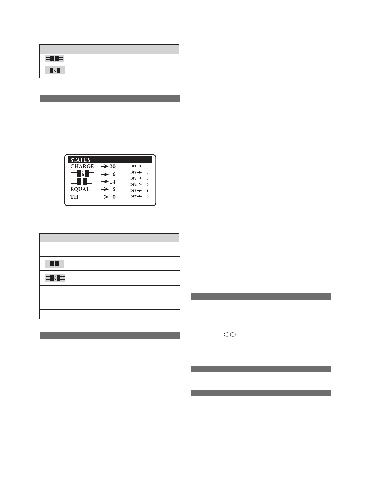
Call-up screen
An example is presented below.
The information displayed
The information on the screen can be reset to zero via the
Reset line on the Configuration Menu.
Message Information
Charge No. of charging operations performed.
This corresponds to the sum of lines 2 and 3.
No. of charging operations terminated
abnormally.
No. of charging operations terminated
normally.
Equal No. of automatic equalisation operations
performed by the charger.
TH No. of thermal faults*.
DF1, etc. No. of fault of types 1, 2, 3, 4, 5 or 7*.
(*) : See ‘Fault Messages’.
Configuration
This menus provides access to the charger’s 12
configuration menus.
Access
On the Main Menu, select Configuration and then press OK.
Profile
This defines the type of battery connected to the charger
from among different types (for example Ionic, Gel or PNEU).
To change the profile, press OK, select a profile from the list
using the ▼/▲ buttons and confirm by pressing OK.
Temperature
This value is adjustable according to the battery technology.
• Without Fiamm Motive Power®energycom: it defines the
battery’s average operating temperature before charging.
• With Fiamm Motive Power energycom: the battery’s
operating temperature is defined automatically. It is
advisable to enter the average temperature recorded,
particularly in cold areas.
Equal time
Only valid for unsealed lead/acid batteries. This defines the
length of the equalisation operation (1 to 8 hours).
Delayed equal
Only valid for unsealed lead/acid batteries. This defines the
delay before equalisation (1 to 8 hours).
Auto equal
Only valid for unsealed lead/acid batteries. This defines the
initiation method: manual or automatic. Select:
• ON for equalisation to start automatically on completion
of charging.
• OFF to prevent automatic equalisation on completion of
charging.
Delayed charge
This defines the delay (1 to 8 hours) between the time
charging is initiated and the time that charging effectively
starts. This time delay enables you to take advantage of ‘
Off-Peak’ tariff times.
Battery rest
This defines the waiting time (1 to 8 hours) after charging
has finished to allow the battery to stabilise.
Electrovalve
This defines the opening time (15 to 120 seconds – Ionic and
Pneumatic profiles only) of the electro-valve for filling the
batteries automatically. When the OK button is pressed, a
function test is immediately initiated for ten seconds. The
operator can therefore check that the electro-valve is
opening correctly.
Range
Only accessible for chargers of the Premium HF flex
48-72-80V type. This defines the battery charging voltage
(48/72V or 48/80V).
Cable length
This defines the length of the cable battery-charger
(1.0 to 10.0m).
Cable section
This defines the cross-section of the cable (battery-charger).
Select a cross-section from the values offered (10, 16, 25, 35,
50 or 70mm
2
).
Reset
This reinitialises the Status and Memory counters after entry
of the password.
Config version
This shows the charger’s configuration version.
Contrast
This modifies the display’s contrast. A zero value shows a
white screen; a value of 100 shows a black screen. The
optimum value depends on the ambient lighting conditions.
If the messages on the display are unreadable (black or
white screen):
1. Hold down and ▲ simultaneously.
2. When the LEDs flash (Fig. 2), adjust the contrast via the
▼/▲ buttons.
3. Confirm by pressing OK.
Backlight
This activates (ON) or deactivates (OFF) the display’s
backlighting.
Language
This selects the language displayed in the menus.
Page 7
8
Unpacking
The charger is supplied with the following components:
• A 2m-long mains cable.
• A 3m-long battery cable.
• The present instruction manual.
Mechanical Installation
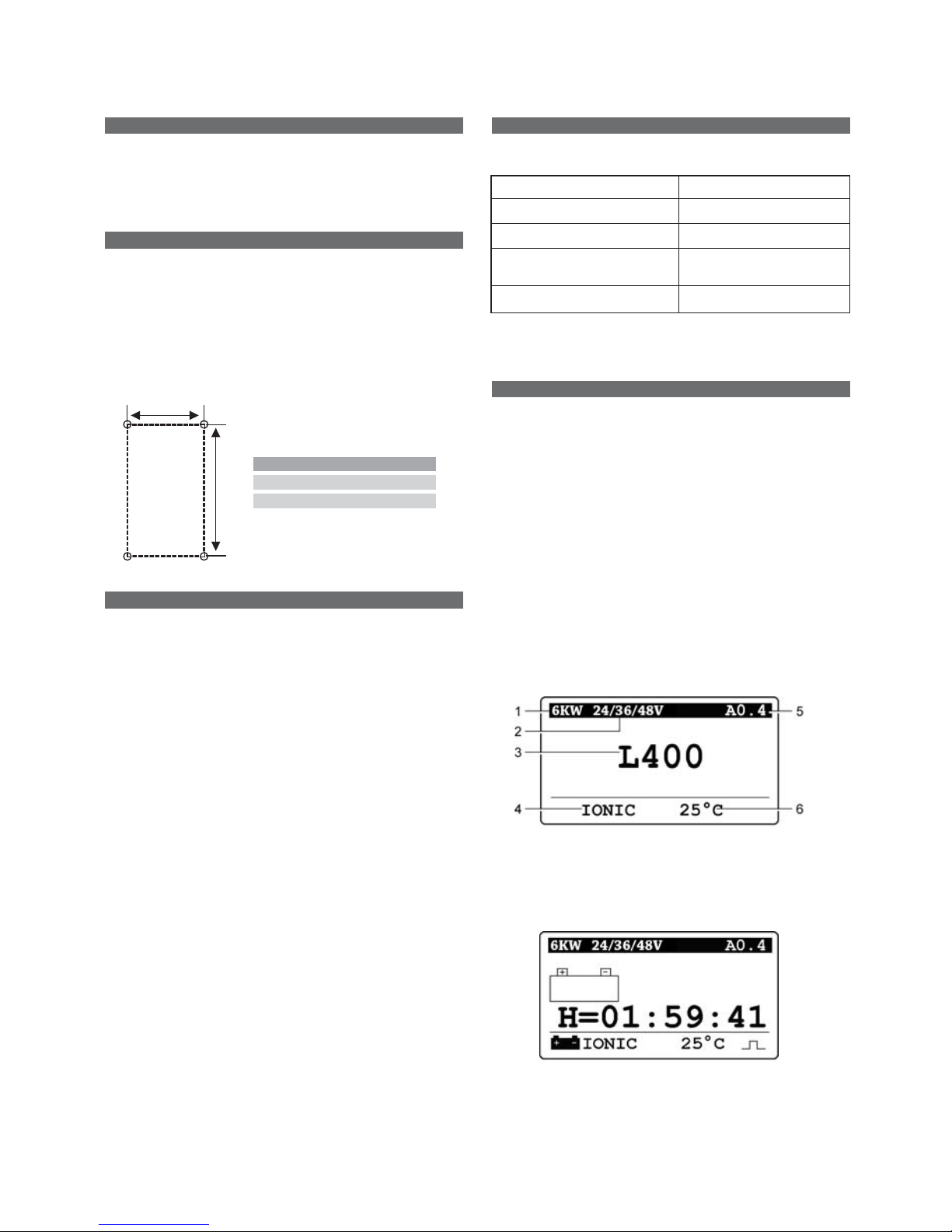
The charger must be mounted on the wall in a vertical
position. The lower part of the charger must be at least
0.60m from the floor and/or the charger below and the
upper part 1.0m from the ceiling. The minimum distance
between two chargers must be 0.30m. You must avoid areas
where the chargers may be splashed with water.
The charger is held by 4 M8 screws suitable for the type of
support. The drilling pattern varies according to the model
of charger. Follow the illustration below.
Electrical Connection
To the three-phase supply
You may only connect to the 3-phase 400V AC mains supply
via a standard socket and an appropriate circuit breaker (not
supplied). The current consumption is shown on the
charger’s information plate.
To the battery
Polarity must be observed. Any reversal of polarity will blow
the output fuse, prevent charging and cause DF2 to be
displayed. Please refer to the Fault Messages section.
The charger must be connected to the battery by the cables
supplied:
• The RED cable: to the battery’s POSITIVE terminal.
• The BLACK cable: to the battery’s NEGATIVE terminal.
Factory Configuration
The charger is supplied with the following factory
configuration:
Profile: As per the order
Output cable length: 4 m
Configuration: As per the order
Automatic equalisation No
selected:
Deferred charging activated: No
• If no modification to the above is desired, please proceed
directly to the section on ‘Charging the battery’.
• If modification is required, go to the Configuration
section.
Charging the battery
When the charger has been configured in accordance with
the Configuration section, it can only be started when a
technically compliant battery is connected to it (type,
capacity, voltage).
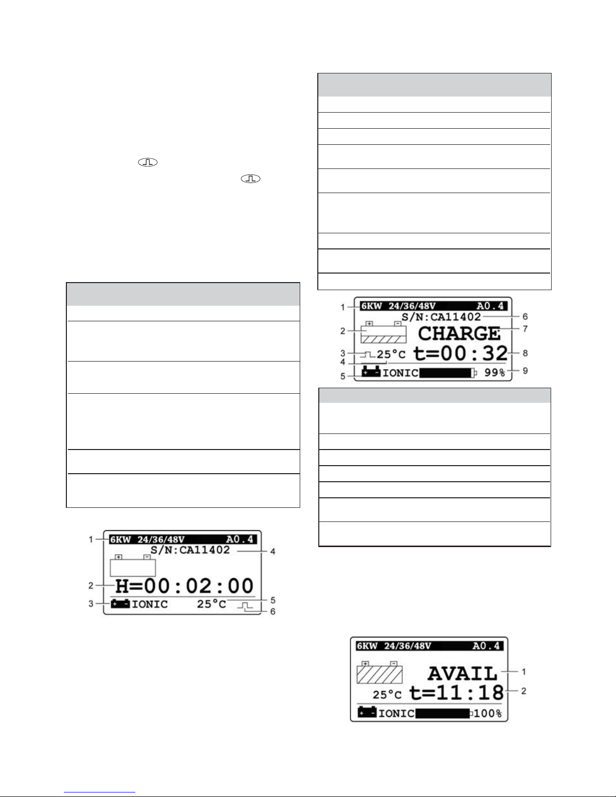
Display when not charging
When the charger is in the waiting position (Start/Stop
switch on “0”) and the OK has not been pressed, the display
shows the information regarding the charger (top and
bottom lines):
1. Type of charger.
2. Charger’s characteristics.
3. ‘Waiting’ status message.
4. Previously selected charging profile.
5. Software version.
6. Selected operating temperature.
Initiating delayed charging
If the charger has been programmed in this way
(Configuration Menu / Delayed Start), charging starts after
the time delay set. The display shows the time remaining
before charging starts.
Use
394
H
H (mm)
Type 1 540
Type 2 540
Page 8
9
Initiating desulphation before charging
Desulphation of an unsealed lead/acid battery:
• Either starts automatically when the battery is heavily
discharged; the length of the desulphating operation is
defined by the charger’s electronics. The charging
process is initiated automatically at the end of the
desulphation period.
• Or is initiated manually, as shown below.
To initiate desulphation manually:
1. Set the Start/Stop switch to “0”.
2. Hold down the button.
3. Set the Start/Stop switch to “1”. Release .
Desulphation is initiated for the programmed period
(“Equal time“ menu). The charging initiation process
must be started manually on completion of the
desulphation period.
Initiating charging
1. Set the Start/Stop switch to “ I “.
The display shows the information on the battery
connected and counts down the time remaining before
effective charging starts.
No. Without With
FMP energycom FMP energycom
1. Type of charger, software version.
2. Countdown for Countdown for 2
2 minutes before minutes maximum
charging effectively before charging
starts. effectively starts.
3. Programmed charging Detected charging
profile – flashing profile – flashing
during this phase. during this phase (*).
4. Empty line. Alternating display of
the voltage, capacity
and the serial number
detected, as the
information is received
and alarms if present (*).
5. Programmed Detected operating
operating T°. temperature (*).
6. Equalisation symbol requested on completion
of charging (see § Completion of charging with
equalisation).
(*) As the information is received.
Once the two-minute countdown is complete, the display
shows the information regarding the charging operation.
Proceed to the section on Effective Charging.
Faults DF1, DF2 and DF3 prevent charging. Please refer
to the section on Fault Messages.
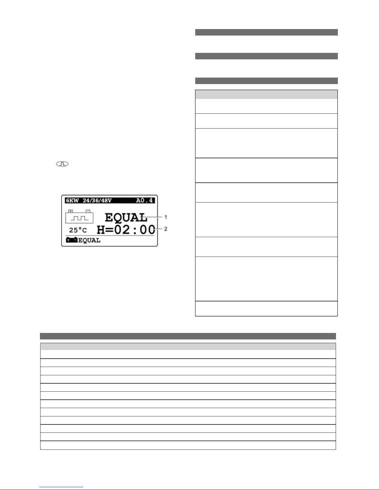
Effective charging
A few moments after charging starts, the display shows the
various charging details in alternation.
No. Without With
FMP energycom FMP energycom
1. Type of charger, software version.
2. Charging symbol. Priority alarm if present.
3. Equalisation requested on completion of charging.
4. Programmed Detected operating
operating T°. temperature.
5. Programmed charging Detected charging profile.
profile.
6. Empty line. Alternation between
the voltage, capacity, the
serial number detected
and alarms if present.
7. Charging indicator.
8. Information updated and displayed cyclically.
Please refer to Table C.
9. Percentage of charge.
Information displayed
Sign Type of measurement Example
U Battery voltage (V). 26.1
u Voltage per cell (V). 2.18
I Instantaneous charging current (A). 55
C Capacity restored (Ah). 71
t Charging time spent (hh:mm). 03:36
H Estimated remaining charging time 05
(hours).
DF No. of any fault occurring. See § Fault DF5
Messages.
Table C: Symbols for the information displayed during charging.
Completion of charging without equalisation
1. The green light (Fig. 2, No. 7) illuminates when charging
has been completed correctly.
The green ‘charging complete’ light (Fig.2, No. 7) is
illuminated and the message AVAIL is displayed (1). The
display shows, in alternation (2):
• The charging time taken.
• The number of amp hours restored.
Please refer to the sections on Memory or Status for details
of the information on completion of charging.
Any other visual indication from any of the three lights
indicates a problem during charging. Please refer to the
Control Panel section.
Page 9
10
If the battery remains connected, in order to keep it charged,
compensation and subsequent equalisation charging
operations will be initiated automatically, depending on the
type of battery.
2. If an equalisation charging operation has been
programmed (unsealed lead/acid battery), this is
initiated automatically.
If this is not the case, equalisation charging can be
initiated manually: please refer to the section on
Completion of charging with equalisation.
3. If the green light is flashing, the battery is in its resting
phase.
Wait until the light stops flashing.
4. Set the Start/Stop switch to “0”.
5. Disconnect the battery, which is now ready for use.
Completion of charging with equalisation
Equalisation only concerns unsealed lead/acid batteries. It
can be initiated either manually or automatically.
Manual initiation
1. As soon as charging is complete (the green light is
permanently lit or is flashing - Fig.2, No. 7), press
the button.
The messages EQUAL I = (equalisation current) and
EQUAL H = (remaining equalisation time) (Nos. 1 and 2
below) indicate that equalisation has been initiated.
2. The battery is ready for use as soon as the green light
(Fig. 2, No. 7) illuminates.
Automatic initiation
If equalisation has been programmed (Configuration Menu /
Equal time, Delayed equal and Auto equal set to ON),
equalisation charging is initiated automatically.
Furthermore, if the battery remains connected, in order to
keep it charged, maintenance charges (compensation and
subsequent equalisation charging operations) will be initiated automatically, depending on the type of battery. The
same information as for manual initiation is displayed (see
above).
Display of the history per charging operation
To display the memorised information and to reset it to
zero, please refer to the Memory section.
Display of the charger’s history
To display the history and to reset it to zero, please refer to
the Status section.
Fault messages
Fault Cause Remedial action
DC Appears before a DF1
fault is displayed.
DF1* Charger fault. Check the power supply
voltage.
DF2* Output fault. Check that the battery is
correctly connected (that
the cables are not
reversed) and the output
fuse.
DF3* Unsuitable battery. Battery voltage too high
or too low. Connect the
correct charger for the
battery
DF4 The battery has been Charging continues.
discharged more than
80% of its capacity.
DF5 Battery requires Check the charging
inspection. cables (cross-section too
small), the terminals
(oxidisation, not tight)
and the battery
(defective elements).
DF7 Pneumatic mixing air Check the air
circuit fault (the red circuit (pump, tubing).
light flashes).
TH* Thermal fault Check that the fan(s)
resulting in is (are) working
interruption of correctly and/or
charging. that the ambient
temperature is not too
high or whether there is
poor natural ventilation
to the charger.
STOP* Critical electrolyte level in the battery.
Fill the battery.
(*): A blocking fault preventing charging from continuing.
Technical characteristics of Premium HF flex
Units 2004 2006 2008 2010
Power supply voltage V 400 ±10% tri 400 ±10% tri 400 ±10% tri 400 ±10% tri
Frequency Hz 50/60 50/60 50/60 50/60
Current absorbed A 7 10 13 17
Power supply cable mm
2
4 x 2.5 4 x 2.5 4 x 4 4 x 4
Power supply fuse A Protistor 20A Protistor 20A Protistor 30A Protistor 30A
Battery cable (1) mm
2
25 25 50 50
Battery cable length m 1 to 10 1 to 10 1 to 10 1 to 10
IP protection level IP20 IP20 IP20 IP20
Operating temp. °C 0 to +40 0 to +40 0 to +40 0 to +40
Display LCD LCD LCD LCD
Weight kg 30 30 30 55
Dimensions (Hx W x D) mm 750x410x317 750x410x317 750x410x317 940x410x317
(1) Take the electrical installation into account when determining the actual cable cross-section.
Page 10

12.2011 / Subject to revisions without prior notice
European Headquarters:
EnerSys EMEA
EH Europe GmbH
Löwenstrasse 32
8001 Zürich
Switzerland
Phone: +41 44 215 74 10
Fax: +41 44 215 74 11
EnerSys Ltd
Oak Court
Clifton Business Park
Wynne Avenue
Swinton
Manchester M27 8FF
Phone: 0161 794 4611
Fax: 0161 727 3809
Please refer to the website address for details
of your nearest EnerSys office:
www.enersys-emea.com
© 2011. All rights reserved.
All trademarks and logos are the property of
or licensed to EnerSys and its affiliates unless
otherwise noted.
 Loading...