

Page 1

MODEL 2314/2316
SNMP ALARM ENCODER
FIAL INCORPORATED
710 CENTER STREET
OREGON CITY, OR 97045
503.607.1940
WWW.FIAL.COM
DOCUMENT NUMBER 2314/2316-042315
COPYRIGHT © 2015 BY FIAL INCORPORATED
Page 2

NOTICE OF FCC COMPLIANCE
NOTE
This equipment has been tested and found to comply with the limits for a Class A
digital device pursuant to Part 15 of FCC Rules. These limits are designed to
provide reasonable protection against harmful interference when this equipment is
operated in a commercial environment. This equipment generates, uses, and can
radiate radio frequency energy and, if not installed and used in accordance with the
instruction manual, may cause harmful interference to radio communication.
Operation of this equipment in a residential area is likely to cause harmful
interference, in which case the user will be required to correct the interference at
his/her own expense.
Page 3

Model 2314/2316 SNMP Alarm Encoder
TableofContents
1 INTRODUCTION .................................................................................................................................. 1
2 DESCRIPTION ..................................................................................................................................... 2
FRONT PANEL LEDS: .............................................................................................................................. 2
ALARM INPUTS: ....................................................................................................................................... 2
Alarm point vs. Status point: ............................................................................................................. 2
Delayed activation: ............................................................................................................................. 2
CONTROL OUTPUTS: .............................................................................................................................. 2
ANALOG INPUTS: .................................................................................................................................... 3
3 INSTALLATION .................................................................................................................................... 4
STATION GROUND CONNECTION (STA. GND) CAUTION .................................................................... 4
ALARM LED OPTOISOLATOR POWER .................................................................................................. 4
AC POWER RECOMMENDATION (AC POWER SUPPLY NOT INCLUDED) ......................................... 5
EXTERNAL I/O CONNECTOR ............................................................................................................. 5
4 CONFIGURING THE SNMP ALARM ENCODER ................................................................................. 7
INITIAL NETWORK CONFIGURATION SETTINGS WITH THE CRAFT SERIAL PORT ......................... 7
COMPLETE CONFIGURATION USING A WEB BROWSER ................................................................. 12
The Alarm Inputs Page ..................................................................................................................... 15
The Analog Inputs Page ................................................................................................................... 19
The Boolean Alarms Page ................................................................................................................ 21
The Event Log Page .......................................................................................................................... 23
The IP Settings Page ........................................................................................................................ 24
The RTC Time/Date Page .................................................................................................................. 27
The SNMP Notifications Page .......................................................................................................... 29
Web Browser interface - Logins and Passwords ........................................................................... 32
The Config File .................................................................................................................................. 34
Firmware Upgrade ............................................................................................................................ 35
Undo All Changes ............................................................................................................................. 36
Save & Reboot ................................................................................................................................... 36
5 CONFIGURING THE SNMP MASTER ............................................................................................... 37
SNMP NOTIFICATIONS: ........................................................................................................................ 37
SNMP CONTROLS: ................................................................................................................................ 37
6 NOTES ............................................................................................................................................... 40
WEB PAGE PROVISIONING CAUTION ................................................................................................. 40
REMOTE WEB OR TELNET PROVISIONING CAUTION ...................................................................... 40
HOSTNAME ............................................................................................................................................ 40
IP ADDRESS RESTRICTIONS ............................................................................................................... 41
LOGIN & PASSWORD ............................................................................................................................ 42
SAVE & REBOOT ................................................................................................................................... 42
WEB & UNIX COMPATIBLE BROWSERS ............................................................................................. 42
Fial Incorporated 2314/2316-042315 i
Page 4

Model 2314/2316 SNMP Alarm Encoder
REPLACING THE RTC BATTERY .......................................................................................................... 43
TRIVIAL FILE TRANSFER PROTOCOL (FIRMWARE UPGRADE) ....................................................... 43
7 CREATING BOOLEAN ALARM POINTS AND EXPRESSIONS ........................................................ 45
8 I/O CONNECTOR PIN DESIGNATIONS ............................................................................................ 52
9 ETHERNET CONNECTOR (RJ-45 JACK) .......................................................................................... 53
10 2314/2316 REMOTE ENCODER SPECIFICATIONS ......................................................................... 55
DC POWER SPECIFICATIONS .............................................................................................................. 56
ii 2314/2316-042315 Fial Incorporated
Page 5

Model 2314/2316 SNMP Alarm Encoder
TABLE OF FIGURES
Figure 1. Model 2314 Front Panel ................................................................................................................ 1
Figure 2. Model 2316 Front Panel ................................................................................................................ 1
Figure 3 . Positive Ground Jumper Power Input Example ............................................................................ 4
Figure 4. Battery Polarity Selection For Optoisolators .................................................................................. 5
Figure 5. Craft Port Login Window ................................................................................................................ 8
Figure 6. Main Menu ..................................................................................................................................... 8
Figure 7. Setting IP Address Via HyperTerminal .......................................................................................... 9
Figure 8. Set Netmask via Craft Screens ...................................................................................................... 9
Figure 9. Set Gateway Via HyperTerminal ................................................................................................. 10
Figure 10. Set Login & Password via Craft Screens ................................................................................... 10
Figure 11. Initial Welcome Page ................................................................................................................. 13
Figure 12. Enter User Name & Password Via The Web ............................................................................. 13
Figure 13. Event Log Page ......................................................................................................................... 14
Figure 14. Alarm Inputs Page Via The Web ............................................................................................... 15
Figure 15. Control Outputs Page Via The Web........................................................................................... 17
Figure 16. Analog Inputs Page Via The Web .............................................................................................. 19
Figure 17. Boolean Alarms Page Via The Web .......................................................................................... 22
Figure 18. Event Log Page Via The Web ................................................................................................... 23
Figure 19. The IP Settings Page ................................................................................................................. 24
Figure 20. RTC Time/Date Page Via The Web ........................................................................................... 27
Figure 21. SNMP Notifications Page Via The Web ..................................................................................... 29
Figure 22. Set Login & Password Via The Web .......................................................................................... 33
Figure 23. Configuration Text Screen ......................................................................................................... 34
Figure 24. Firmware Upgrade Via TFTP ..................................................................................................... 35
Figure 25. Undo All Changes Screen ......................................................................................................... 36
Figure 26. Save & Reboot Screen .............................................................................................................. 36
Figure 27. Browse encControlPointTable ................................................................................................... 38
Figure 28. Setting Spinlock Variable ........................................................................................................... 38
Figure 29. Set Request with Spinlock and Control Point State Variables ................................................... 39
Figure 30. TFTP Server Window ................................................................................................................ 44
Figure 31. TFTP Server Directory Window ................................................................................................. 44
Figure 32. Boolean Alarms Screen ............................................................................................................. 45
Figure 33. First point in Boolean Expression .............................................................................................. 47
Figure 34. Partial Simple AND Expression ................................................................................................. 47
Figure 35. Completed Simple AND Expression .......................................................................................... 48
Figure 36. Second Boolean Example ......................................................................................................... 49
Figure 37. Completed Unasserted Condition Expression ........................................................................... 49
Figure 38. Simple OR’d Expression ............................................................................................................ 50
Figure 39. Creating a Complex Boolean expression ................................................................................... 51
Fial Incorporated 2314/2316-042315 iii
Page 6

Model 2314/2316 SNMP Alarm Encoder
TABLE OF TABLES
Table 1. Analog Input Attenuation Versus Frequency ................................................................................... 3
Table 2. Notification/Trap and Inform Request Settings ............................................................................. 31
Table 3. Login Names and Passwords ....................................................................................................... 32
Table 4. Table of Netmasks and Addresses ............................................................................................... 41
Table 5. 2314/2316 I/O Connector Pin Assignment .................................................................................... 52
Table 6. Ethernet Connector Pin Assignments ........................................................................................... 53
Table 7. Straight-Through Ethernet Cable Wiring (T-568B Color Code) ..................................................... 53
Table 8. Cross-Over Ethernet Cable Wiring - opposite end ........................................................................ 54
iv 2314/2316-042315 Fial Incorporated
Page 7
Model 2314/2316 SNMP Alarm Encoder
1 Introduction
The 2314 and 2316 SNMP Alarm Encoders are remote devices for use with SNMP network managers.
The 2314 encodes 8 input alarm points. The 2316 encodes 16 input alarm points. Both units encode 16
Boolean (composite) alarm points, 8 analog input voltages and include 4 Form-C control relay outputs
(control points). The Boolean alarm points are created by entering Boolean expressions that combine the
true/false state of any alarm point, status point, control point or analog point using the AND, OR, XOR and
NOT operators. A 10/100BaseT LAN port connects to an IP network for access by any SNMP V2
compatible manager. With the exception of the number of alarm inputs, both the 2314 and 2316 SNMP
Alarm Encoders are identical in operation.
The 2314/2316 SNMP Alarm Encoder is provisioned using a Web browser. An RS232 craft interface can
be used to set IP Address, Netmask and Gateway. A Web browser can also be used to view the current
state of all alarms, the current values of analog inputs and to activate or deactivate any control relays. Web
access login is secured by an authorized user name and password. There are three levels of
authorizations provided: one for viewing only, one for viewing and issuing controls, and one for
administrative configuration functions. A secure HTTPS (port 443) web connection is also available if
higher security is required.
Both the 2314 and the 2316 also include a Form-C summary-alarm relay. The summary relay operates
(closes) for any critical (CR), major (MJ) or minor (MN) alarm. A status (ST) alarm does not cause the
summary relay to close.
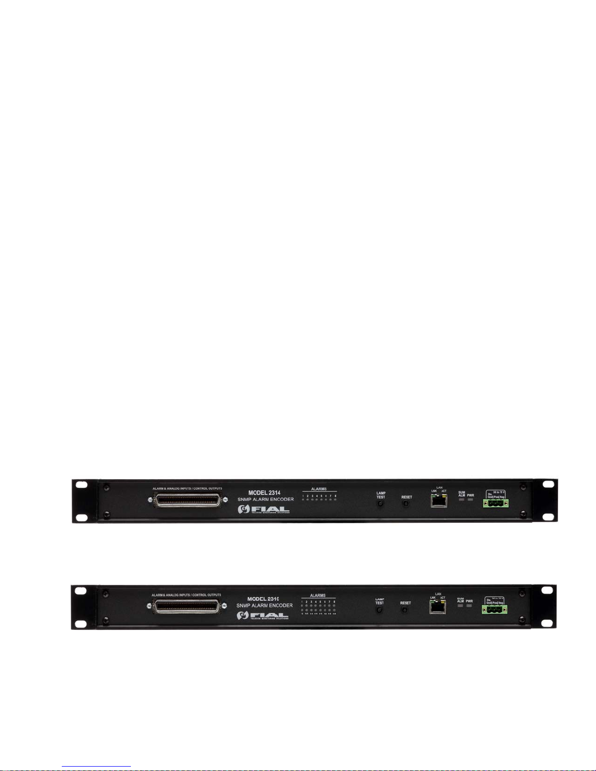
The front panel contains LED indicators for power, summary alarm, LAN connection status (link, activity),
and individual alarm (or control point) states. The 2314 displays a single row of 8 alarm input LEDs, while
the 2316 displays 16 alarm input LEDs, in 2 rows of 8 LEDs each. All connections are on the front panel.
The rear panel is blank.
Figure 1. Model 2314 Front Panel
Fial Incorporated 2314/2316-042315 1
Figure 2. Model 2316 Front Panel
Page 8

2 Description
Front Panel LEDs:
The Model 2314/2316 SNMP Alarm Encoder includes front panel LED indicators for unit power
(PWR), summary point state (SUM ALM), and LAN connection and activity status (LINK & ACT).
The 2314 includes 8 individual front panel alarm point status LEDs, while the 2316 includes 16
individual alarm point status LEDs (2 rows of 8 alarms each). These red LEDs display the current
states of the unit’s alarm points. LEDs are illuminated for asserted (ON) alarms (or controls - see
below).
Pressing the Lamp Test button turns all front panel LEDs on (except the two LAN indicators) to test
lamp functionality. If you hold the Lamp Test button down for over 3 seconds, then the first four top
row LEDs (1 through 4) will show the current state of the 4 control relays. Releasing the LAMP
TEST button returns all LEDs to their normal function.
Alarm Inputs:
The alarm inputs are optically isolated. Alarm inputs can be asserted either by connecting the
input to station ground (normal input), or by removing ground from the input (inverted input). Each
alarm input can be set for a delay (up to 9999 seconds) before asserting an alarm. The external
device driving the inputs must handle a current of 2 milliamperes. The alarm inputs are scanned
every 200 milliseconds. The alarm input connector is a female 50-pin CHAMP (AMP) on the front
panel.
Model 2314/2316 SNMP Alarm Encoder
Alarm point vs. Status point:
Each of the alarm inputs may be configured to be an alarm point or a status point. Once
asserted, an alarm point is latched until read (polled). Status points are not latched, this
means the state of the point changes in real-time with the state of the input pin.
Delayed activation:
Each of the alarm inputs may have a delay associated with it. This is useful when you
want to ignore short, intermittent events. The delay may be set from one second up to
about 9999 seconds (2.77 hours). For example, if an input has a 10 second delay set,
then the point must be continuously asserted (uninterrupted) at the input pin for a minimum
of 10 seconds before the alarm point is considered ‘ON’ in the 2314/2316.
Control Outputs:
The 4 control outputs are provided by activation of Form-C relay contacts (normally open, common,
and normally closed contac
ts). The Form-C contacts allow the power-off default to be wired as
normally off or normally on. The relay output connector is a female 50-pin CHAMP mounted on the
front panel. The contacts are rated for 1 Amp up to 48 volts DC, 0.6 Amps at 110 volts DC, and
0.6 Amps at 125 volts AC.
2 2314/2316-042315 Fial Incorporated
Page 9

Model 2314/2316 SNMP Alarm Encoder
The default mode of operation for the control point is ON/OFF. An SNMP 'set' command of ON will
close the relay, and a set OFF command will open the relay. The configuration program also
allows you to make any of the outputs act in a momentary fashion. If momentary is selected, then
the relay is operated for 200 milliseconds for ON command. OFF commands are ignored for relays
configured as momentary.
Analog Inputs:
Both the 2314 and 2316 have 8 analog (voltage measuring) inputs. Each input can measure a
voltage range of negative 90 volts to positive 90 volts.
The analog inputs are generally measured relative to a common ground. However, fixed pairs of
inputs may be set to differential input mode. A maximum of 4 differential pairs is possible. In
differential mode, the measurement is made between the two inputs of the pair, rather than
between an input and ground. For example, if input 1 is set to differential mode, then input 1
becomes the positive input and input 2 becomes the negative input of the pair. If input 3 is set to
differential mode, then input 3 becomes the positive input and input 4 becomes the negative input
of the pair, and so on. The configuration program allows you to choose either single-ended
(standard) vs. differential pair mode for analog inputs.
The input resistance for each analog input is 698k Ohms to ground.
Each analog input is RC low-pass filtered in order to reject higher frequencies. The time constant
is approximately 0.05 seconds. The attenuation versus frequency table is below.
Frequency Attenuation
DC (0 Hertz) 0x
5 Hz 1.6x
10 Hz 2.8x
20 Hz 4.1x
60 Hz 14.5x
120 Hz 29.2x
240 Hz 58.3x
1000 Hz 175x
Table 1. Analog Input Attenuation Versus Frequency
Shielded wire is recommended for connecting distant measuring points to the input connector, and
shielded pair cable is recommended for connecting differential inputs to the input connector.
Fial Incorporated 2314/2316-042315 3
Page 10
3 Installation
This 1U unit can be installed in 24 or 48 volt stations (18 to 72 volts operation) with either positive
ground or negative ground. NOTE: Original 2314/16 units (sold prior to April 2011 serial#
1116062) were 48-volt-only units. The factory default is for Positive ground operation. The
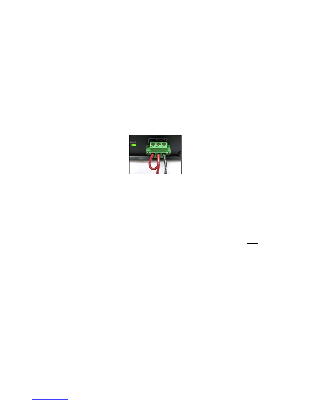
2314/2316 SNMP Alarm Encoder is shipped with a 3-wire plug (snap-in DC power connector) with
screw terminals.
The left-most connection (Sta Gnd) is chassis ground and must be grounded to station ground
(rack ground). This ground wire is the return path to the battery for alarm inputs. For Positive
Ground stations, this wire must have a conductive path back to the battery's Positive terminal. For
Negative Ground stations, this wire must have a conductive path back to the battery's Negative
terminal. The power input is reverse-voltage protected and under/over voltage protected.
Model 2314/2316 SNMP Alarm Encoder
Figure 3 . Positive Ground Jumper Power Input Example
Mounting ears are supplied for flush mounting in a 19-inch rack. The mountings may be reversed
for 1.75-inch projection mounting.
STATION GROUND CONNECTION (STA. GND) CAUTION
Some telecom sites may require all station battery connections to be grounded at only one point
near the battery bank. If your installation requires an isolated station battery input, you must run
the Sta Gnd wire from the power connector at the front of the unit to a rack-ground so it gets to the
station battery ‘common’ via the station ground.
Important! Do not attempt to operate the equipment without a dedicated station ground (STA.
GND, chassis ground, rack ground) connection, as electrical damage may occur. The unit’s rack
mounting screws alone will not provide a reliable rack ground due to their anodized surfaces. This
ground is also a reference ground for the alarm inputs, and this ground is also provided on the
alarm-input connector. See the following Alarm LED Optoisolator Power section.
ALARM LED OPTOISOLATOR POWER
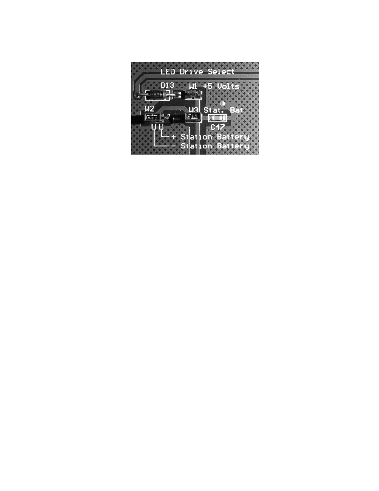
There is an internal jumper (see Figure 4) that selects the negative or positive lead of the battery
input to power the alarm input optoisolat
ors. For POSITIVE GROUND systems (factory default)
the jumper should be in the NEGATIVE - Station Battery position. This selects the proper polarity
voltage input to power the optoisolators. For NEGATIVE GROUND systems, the jumper must be
switched to the POSITIVE + Station Battery position. If this jumper is in the wrong position, an
alarm input will not be asserted when the alarm input is connected to Station Ground.
4 2314/2316-042315 Fial Incorporated
Page 11
Model 2314/2316 SNMP Alarm Encoder
Figure 4. Battery Polarity Selection For Optoisolators
AC POWER RECOMMENDATION (AC power supply not included)
For the wide range 18 to 72 VDC supply voltage 2314/2316 RTUs, if DC Station Battery is
unavailable and an AC power supply is required, the use of a 24V, 1.5 to 2.0 amp wall-mount or
desktop style switching power supply is recommended. These power supplies may be purchased
from many different sources and generally cost around $20 to $30. The power supply DC
connector (typically a barrel style plug) will need to be removed and the power supply lead wires
connected to the appropriate 2314/2316 DC power input connector terminals (provided with the
unit). Connect the power supply Positive lead to the Positive input connector terminal and the
power supply Negative lead to the Negative input connector terminal. The 2314/2316 DC power
input connector Sta. Gnd terminal needs to be connected (jumper wire) to the proper power supply
input terminal, which will depend on the ground reference used for the equipment connecting to the
2314/2316 Alarm Inputs. Make sure to follow the previous instructions regarding Station Ground
requirements on page 4.
LAN CONNECTION: The SNMP Alarm Encoder is connected to the IP network using an Ethernet
RJ45 jack and standard 10BaseT or 100BaseT wiring. The LAN port will automatically switch to
10BaseT or 100BaseT, depending on the connection type at the other end of the cable.
EXTERNAL I/O CONNECTOR
A 50-pin Champ (AMP) connector is used for alarm input, analog inputs and relay outputs.
It is best to order a pre-assembled cable assembly from a company such as Grayhill. One easy
option is to use a cable with a 50-pin AMP connectors at each end and a 66M block (punch-down
block) pre-wired to a 50-pi
should be a male, connector. The other end should mate with the 66M block. 66M blocks can be
ordered with male or female connectors. The punch down block can be mounted on the wall, and
all the station connections brought to that block. Follow the pin assignments for the connector
detailed at the end of this document (Table 8-1).
Fial Incorporated 2314/2316-042315 5
n AMP connector. The cable end that connects to the 2314/2316
Page 12

Model 2314/2316 SNMP Alarm Encoder
RELAY OUTPUTS:
Note the pin numbers carefully. Follow the pin assignments for the connector detailed at the end of
this document (Table 5).
ANALOG INPUTS
The connector has separate pins for station ground and analog ground. These are connected
together at the 'common' measurement point on the analog board.
Single ended measurements may be connected between an analog input pin and analog ground.
For the most accurate measurements, a pair of wires should run from the device being measured
to the model 2314/2316, with the 'ground' wire connected to an analog ground pin and the active
wire connected to the analog input pin. A shielded wire is recommended for electrically noisy
environments, and a shielded pair is recommended for differential input measurements.
The analog inputs are low pass filtered. There is no attenuation for frequencies below 1 Hertz. A
60-Hertz signal is attenuated 14.5 times relative to DC. Table 1 on page 3 contains attenuation
data for other frequencies.
The main steps involved in installing a Model 2314/2316 SNMP Alarm Encoder are:
Step 1: Install the unit in a 19-inch rack and connect to station battery (verify power polarity and
station ground connections). Connect the LAN cable, and 50-pin I/O cable.
Step 2: (Factory New units) Configure the unit with the proper IP address/netmask/gateway
settings. Use either the RS-232 Craft Port or Web Browser to edit the factory default
addresses. Verify that the device replies to pings for the new settings from another site in
your network. This confirms that gateway IP address and netmask are correct. If you
cannot ping the unit, check the settings using the craft interface (9600 8N1). If the unit
responds to pings, most other problems can be resolved remotely using the web interface.
Use the Web browser interface to connect to the 2314/2316 using the new IP address and
finish configuring the rest of the 2314/2316 SNMP Alarm Encoder settings.
Step 3: It is a good idea to verify that all alarm inputs, control relay outputs and analog voltage
inputs are working properly before leaving the site. This is easily done on-site using the
web interface.
Step 4: Configure your SNMP manager for the 2314/2316 SNMP Alarm Encoder. Compile the
Fial Incorporated registry MIB (fial-registry-mib.mib) and the Fial Incorporated Encoder MIB
(fial-enc-mib.mib) into the manager. Note: Fial Inc. Encoder MIB is used for the 2311,
2314 and 2316 SNMP Encoder products. Add the Network Elements to be monitored.
6 2314/2316-042315 Fial Incorporated
Page 13

Model 2314/2316 SNMP Alarm Encoder
4 Configuring the SNMP Alarm Encoder
Each SNMP Alarm Encoder must be configured prior to use. A default IP address (192.168.1.200,
netmask 255.255.255.0, gateway 192.168.1.200) is preset in each SNMP Alarm Encoder shipped from the
factory; however, you must set the actual IP address the device will use in your network. In addition, you
must configure settings that allow SNMP managers to access and control the unit, and that regulate the
sending of SNMP V2 notifications (autonomous messages or ‘traps’).
The 2314/2316 SNMP Alarm Encoder must be provisioned using a Web browser. However, a craft
interface (RS-232 (9600 8N1) is also available for initially setting IP address, netmask, gateway and
administrator name/password should you be unable to connect using a Web browser. The craft interface
screens are also accessible remotely via a telnet connection.
All 2314/2316 SNMP Alarm Encoders provisioning and configuration should be performed using a Web
browser. The Web pages also provide a configuration download /upload function. This allows one unit’s
setting to be saved and uploaded to other units. See Complete Configuration using a Web Browser on
page 12.
The web interface will not be accessible if you do not know the device's current IP settings. The physical
craft port is always accessible for changing the IP settings.
Initial Network Configuration Settings with the Craft Serial Port
The Craft (serial) port interface uses RJ45 pins 4, 5 and 8 to provide an RS-232 connection for a PC COM
port. The connections are shown in Table 8-2. The usual connection is with HyperTerminal at 9600 baud,
8-data bits, no-parity and 1-stop bit. Set Flow Control to ‘none.’ Power up the SNMP Alarm Encoder and
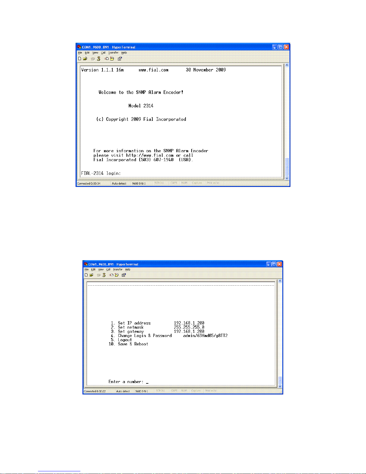
after about 30 seconds the login prompt will appear (see Figure 5). The configuration menu is identical for
both 2314 and 2316 encoders.
Fial Incorporated 2314/2316-042315 7
Page 14
Model 2314/2316 SNMP Alarm Encoder
Figure 5. Craft Port Login Window
Log in with the proper user name and password. The factory default Administrator login name is admin
and the factory default password is remote. The Main Menu will then be displayed.
8 2314/2316-042315 Fial Incorporated
Figure 6. Main Menu
Page 15
Model 2314/2316 SNMP Alarm Encoder
The Main Menu window has a list of several options for configuring the SNMP Alarm Encoder. To
configure the device, complete the following steps:
1. Set the IP Address
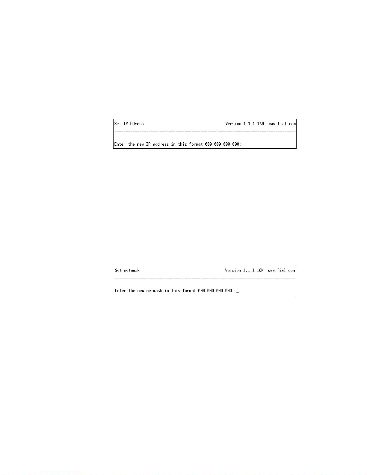
To set a new IP Address for your SNMP Alarm Encoder, select 1 and press Enter. The
Set IP Address window will appear.
Figure 7. Setting IP Address Via HyperTerminal
After the prompt, enter the new IP address and press Enter.
NOTE: Do not select option 10 (Save & Reboot) until you have made any related netmask
and gateway changes and then double-checked them. Not doing this may render the
device inaccessible from the LAN (See IP Address restrictions on page 41).
2. Set the Netmask
To set the new netmask for the SNMP Alarm Encoder, select option 2 and press Enter.
The Set netmask window will appear.
After the prompt, enter the netmask and press Enter.
NOTE: Do not select option 10 (Save & Reboot) until you have made any other changes
for the device and verified them. Doing otherwise may render the device inaccessible from
the LAN. (See IP Address restrictions on page 41).
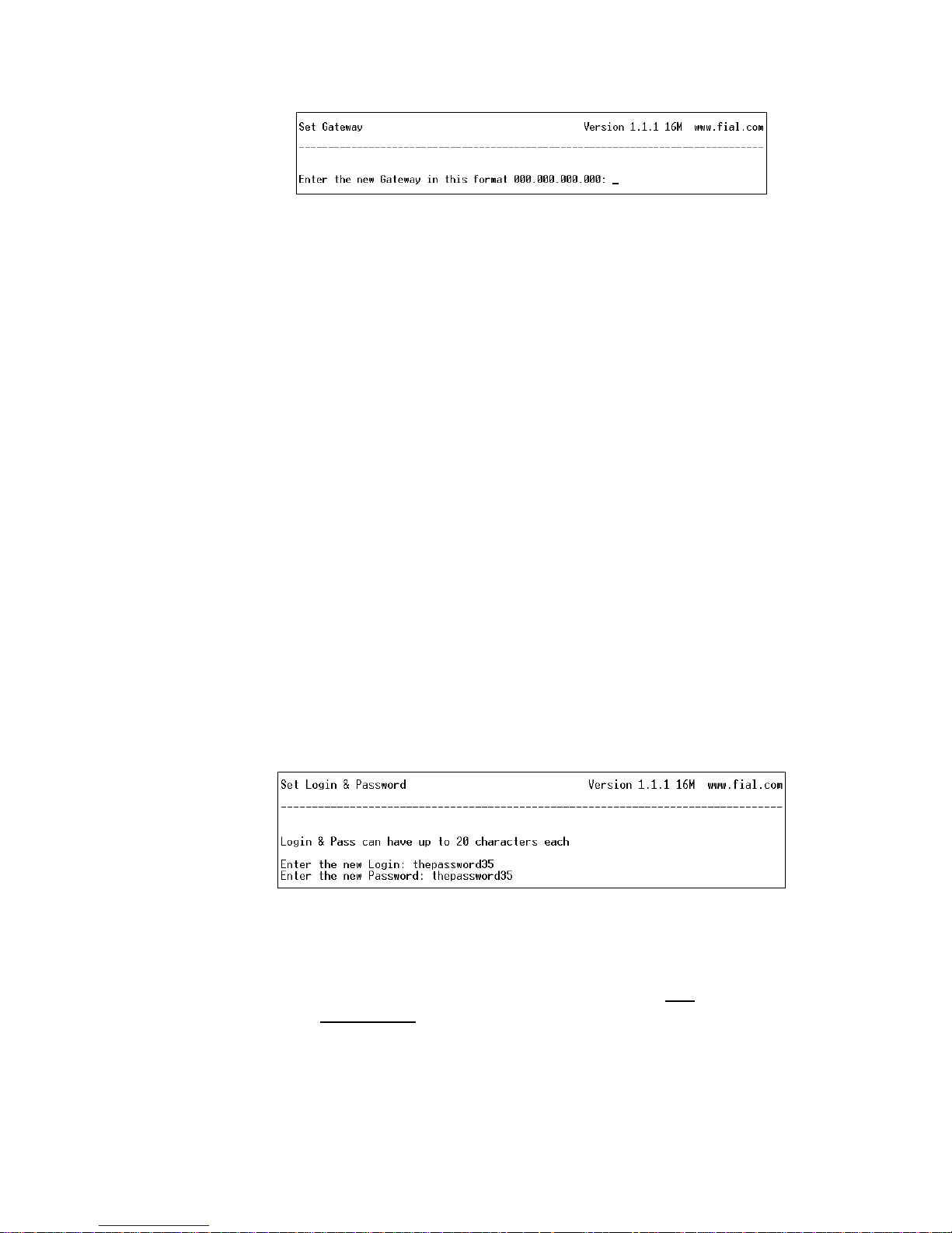
3. Set the Gateway
To set the new gateway for the SNMP Alarm Encoder, select option 3 and press Enter.
The Set Gateway window will appear.
Figure 8. Set Netmask via Craft Screens
Fial Incorporated 2314/2316-042315 9
Page 16
Model 2314/2316 SNMP Alarm Encoder
Figure 9. Set Gateway Via HyperTerminal
After the prompt, enter the Gateway address and press Enter. The gateway address
should be an IP address of the IP router port to which the 2314/2316 is connected. The
router should provide a network connection that reaches the SNMP manager(s).
NOTE: Do not select option 10 (Save & Reboot) until you have made any other changes
for the device and verified them. Doing otherwise may render the device inaccessible from
the LAN. (See IP Address restrictions on page 41).
4. Change Login & Password
Each SNMP Alarm Encoder has a default login (admin) and password (remote)
programmed at the factory. Both the login name and password are case sensitive. Any
user with the administrator login and password will have access to the Craft port of the
device and web page configurations. For security purposes, it is recommended that the
login names and passwords for each device be changed during the initial configuration.
If you forget the new login/password or are unable to log in to the device, the administrator
login and password can be reset to the factory default by holding down the lamp test
button while the device is restarted (reset). You must hold down the button for
approximately 40 seconds until the power-on lamp test is done. No other provisioning
(such as IP address) will be affected.
To change the administrator login name and password for an SNMP Alarm Encoder, select
option 4 and press Enter. The Set Login & Password window will appear.
Figure 10. Set Login & Password via Craft Screens
To change the login and password, follow the prompts: enter the new login, enter the new
password, and then re-enter the new password. Remember that both
password are case sensitive
. A-Z, a-z, 0-9, and hyphen are the only characters allowed
the login and
for the login. The password can be any combination of charters, numbers and special
characters. Passwords should be longer than 8 characters in length. For more
information, refer to Login & Password in the Notes section on page 42.
10 2314/2316-042315 Fial Incorporated
Page 17

5. Logout
To log out of the SNMP Alarm Encoder configuration session, type 5 and press Enter. If
you are using HyperTerminal you will be logged out of the device and presented with the
login screen again. If you connected using telnet, Logout will close your telnet connection.
NOTE: If you have changed settings, then select 10 (Save & Reboot) before logging out.
6. Save & Reboot
After all changes have been made for the SNMP Alarm Encoder, choose option 10 (Save
& Reboot). This will save your changes, and the device will restart with the new settings.
If you do not choose Save & Reboot, any changes made in this login session will not take
effect. The reboot process takes 30 to 40 seconds to complete.
Model 2314/2316 SNMP Alarm Encoder
Fial Incorporated 2314/2316-042315 11
Page 18

Model 2314/2316 SNMP Alarm Encoder
Complete Configuration using a Web Browser
To provision a new 2314/2316 SNMP Alarm Encoder using a Web browser, you must know the IP address
of the device and be able to ping the unit. You can connect the encoder directly to a computer with an
Ethernet Crossover cable (see Cross-Over Ethernet Cable Wiring - opposite end on page 54), or connect
both your computer and the SNMP Alarm Encoder to a hub or a switch with a standard Ethernet cable.
The computer should have Microsoft Internet Explorer Web browser 6.0 or later, or Netscape 7.1 or later or
Firefox as a default Web browser. For Netscape 7.1, verify that Enable JavaScript for Navigator is
“checked” in the Edit/Preferences/Advanced/Scripts & Plugins/Verify device. Most Opera and Mozilla
browser releases will also work.
If this is a factory new 2314/2316 and you are ONLY connecting the LAN port on your computer and on the
encoder together, set your computer to an IP address in the range of 192.168.1.2 to 192.168.1.253,
netmask to 255.255.255.0. Set your gateway address to match the IP address of your computer. (Do NOT
use IP address 192.168.1.200, since this is the SNMP Alarm Encoder factory default address).
For example, set your computer IP address to 192.168.1.10, your netmask to 255.255.255.0, and your
gateway to 192.168.1.10. Open your Web browser program.
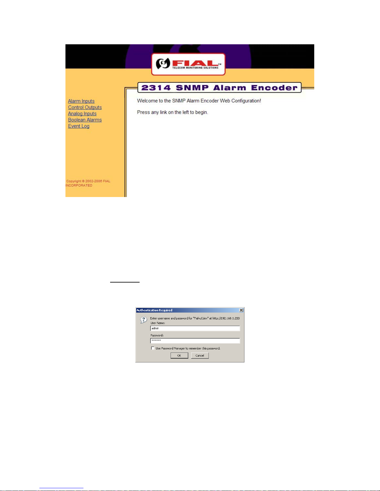
If this is the initial configuration of the SNMP Alarm Encoder, enter http://192.168.1.200 into the browser’s
URL/address bar and press Enter. The SNMP Alarm Encoder Welcome page should appear, (see Figure
11).
If the Model 2314/2316 IP address has already been changed, you will need to know its current IP address
in order to connect using a Web browser. Enter the current IP address of the encoder in the browser’s
URL/address bar. If you do not know the unit’s current IP address, you may find this out (or change it)
using the serial Craft port interface.
Warning: When you change the IP address, gateway and netmask using the Web browser or telnet
interface, you will probably lose your IP connectivity with the device. This will happen when you choose
Save & Reboot. If the device is local, you may then need to change your computer IP settings to access
the 2314/2316 SNMP Alarm Encoder's web server. You normally do not want to change the IP
address, netmask or gateway if the device is remote from you!
12 2314/2316-042315 Fial Incorporated
Page 19
Model 2314/2316 SNMP Alarm Encoder
Figure 11. Initial Welcome Page
The left side of the Welcome page has links to other pages, such as Alarm Inputs, Control Outputs,
Analog Inputs, Boolean Alarms and Event Log. To view the Event Log page or make any changes to
the provisioning, you must first select a menu item on the left side to begin a login dialog.
To access any of the main Welcome page options, click on the hot links in the left pane. Click on a link on
the left, for example the Event Log link, and the Enter Network Password login screen will appear (see
Figure 12). You must log in with a valid user name and password to access any of the links.
Figure 12. Enter User Name & Password Via The Web
If this is the first time the device has been provisioned, enter the factory set administrative user name
(admin) and password (remote) in the fields and click OK. Both entries are all lowercase. Otherwise,
enter the correct user name and password for administrative privileges in the appropriate fields and then
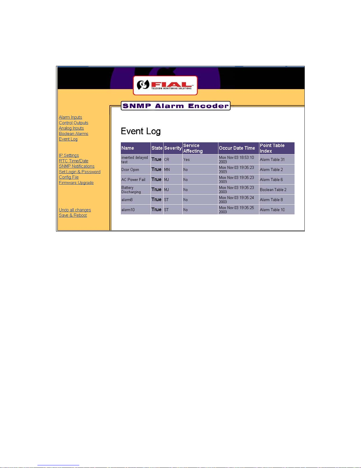
click OK. This opens up the initially selected link page, such as the Event Log page (see Figure 13).
Fial Incorporated 2314/2316-042315 13
Page 20
Model 2314/2316 SNMP Alarm Encoder
Figure 13. Event Log Page
Now that you have logged in with administrative permissions, a new set of links have been added to all of
the pages. They are IP Settings, RTC Time/Date, SNMP Notifications, Set Login & Password, Config
File, Firmware Upgrade, Undo all changes and Save & Reboot. For more login related issues, refer to
Login & Password in section 6 - Notes.
14 2314/2316-042315 Fial Incorporated
Page 21
Model 2314/2316 SNMP Alarm Encoder
The Alarm Inputs Page
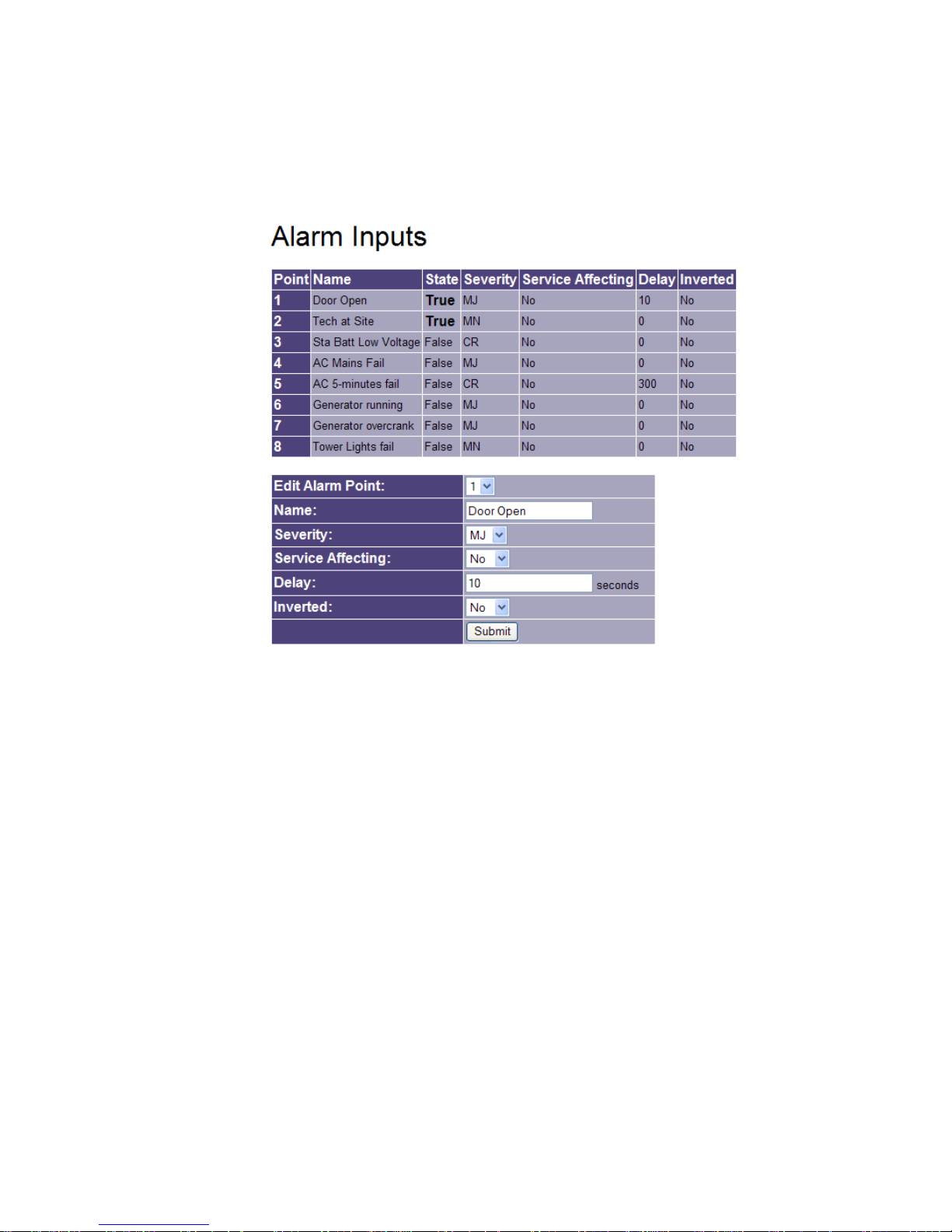
To provision or modify an Alarm point, click the Alarm Inputs link in the left pane. The Alarm Inputs page
will appear, as shown in Figure 14.
Figure 14. Alarm Inputs Page Via The Web
The Alarm Inputs page (as shown in Figure 14), displays the provisioning table for the 8 external alarm
points in this unit. You may have to use the thumb bar to view all alarm points. Alarm information includes
Alarm Point number, Name, current State, Severity, Service Affecting, Delay period and Inverted condition.
You need not provision points that are unused, but all 8 points are always present in the table as viewed by
an SNMP manager. Use the dialog table at the bottom of this screen to provision each alarm point. The
dialog table does not appear if the user is not logged in with administrator privileges. To provision an alarm
point, edit the following fields found at the bottom of the screen:
Edit Alarm Point: Use this drop-down box to select the alarm point you wish to edit.
Name: Enter a name for the selected alarm. Any characters are allowed in this field. Alarm names
can be the same as other alarms; however, this is not recommended for obvious reasons.
Names may be up to 29 characters long. The column width adjusts to fit the name.
Severity: Select the Severity level for the selected alarm point. The possible Severity levels are:
CR, MJ, MN, and ST. Only CR, MJ and MN generate notifications when asserted. To make
Fial Incorporated 2314/2316-042315 15
Page 22

Model 2314/2316 SNMP Alarm Encoder
ST (status) points generate notifications, choose YES to 'Add ST events to the event log' on
the IP Settings web page.
Service Affecting: Select Yes if the selected alarm point is Service Affecting, or No if the selected
alarm point is Not Service Affecting. The term ‘Service Affecting’ means that traffic has been
dropped or that a major communications disruption has occurred.
Delay: Enter the Alarm Delay in seconds for the selected Alarm. Only the digits 0-9 are allowed.
The maximum Delay for an Alarm is 9999 seconds (2.77 hours). The Delay is the amount of
time the alarm input pin must remain asserted before the State is changed to True. For
example, an alarm with a Delay of 30 seconds must be continuously asserted (grounded) for
30 seconds before the State is changed to True. If the assertion state of the point is ‘inverted,’
then the input pin must remain floating or connected to station battery (not grounded) for 30
continuous seconds before the State is changed to True.
Inverted: Select Yes if the selected Alarm is Inverted, or Select No if the Selected Alarm is Not
Inverted. The factory default is No. ‘No’ means the alarm is asserted by connecting the alarm
input pin to station ground. Yes (inverted) means the alarm input pin is normally connected to
station ground, and that the alarm is asserted when the pin is disconnected from ground
allowing it to be pulled to station battery.
Once all changes have been made, press the Submit button. The Submit button must be pressed to
register any changes made on each screen. Changes are stored in a temporary file on the device, keyed
to your IP address. You can submit changes on many different screens before doing a Save & Reboot.
To actually install the changes, the Save & Reboot link on the left side must be selected, and you must
confirm the request by again entering the administrator name and password. Others are thus prevented
from entering changes if you leave your desk. If you do not choose Save & Reboot, your submitted
changes will be erased after a few hours of inactivity.
After the unit reboots, you need not log in again unless you have restarted your Web browser. This is
because your Web browser still holds proper authentication keys. However, if you restart your Web
browser, you will have to log in again. The SNMP Alarm Encoder does not store HTML ‘cookies’ on your
computer.
16 2314/2316-042315 Fial Incorporated
Page 23
Model 2314/2316 SNMP Alarm Encoder
The Control Outputs Page
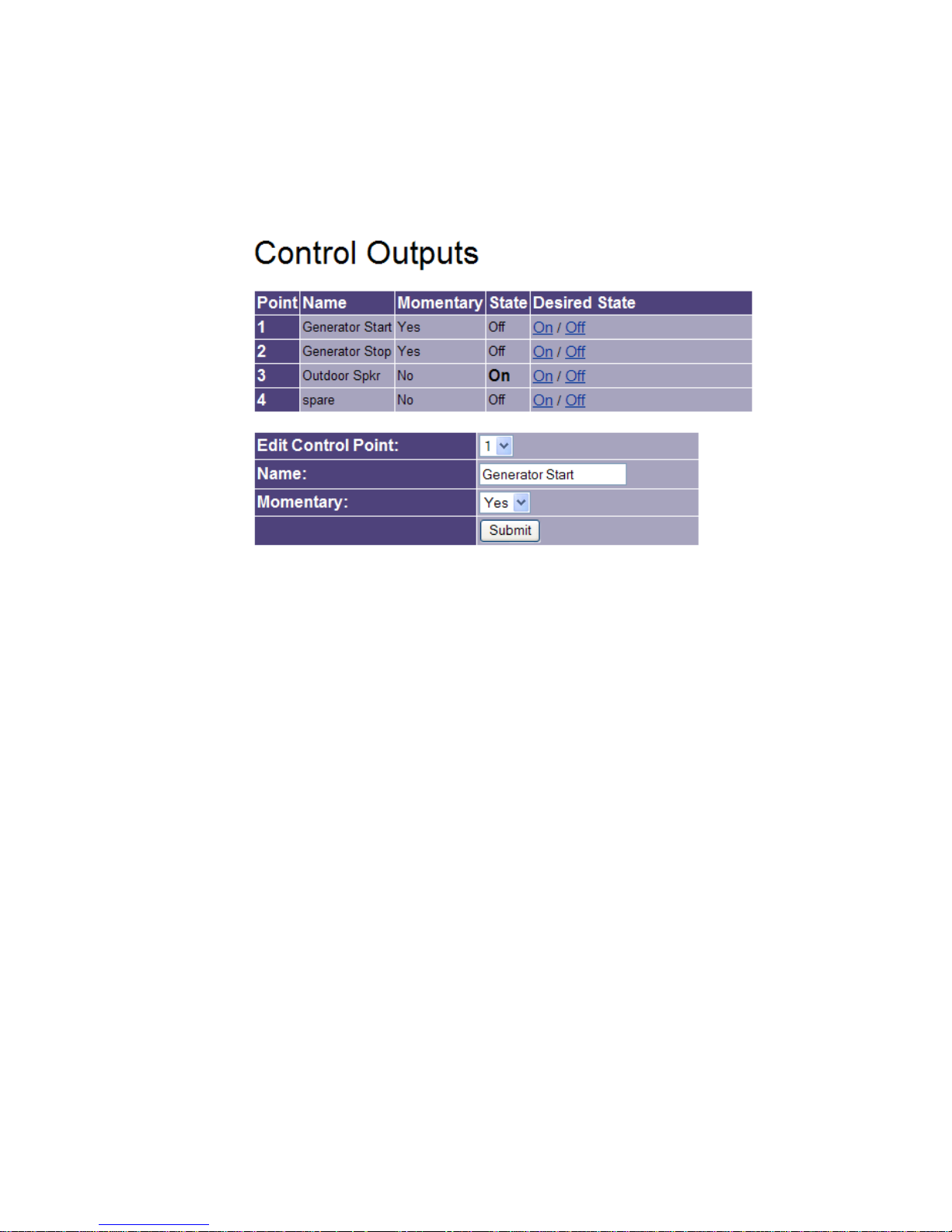
The SNMP Alarm Encoder has 4 Form-C relays, called control points. To provision or modify a control
point, click the Control Outputs link in the left pane. The Control Outputs page will appear, as shown in
Figure 15.
Figure 15. Control Outputs Page Via The Web
This page displays the table for the 4 Control Points. Control information includes: Control Point number,
Name, Momentary action setting, current State and Desired State. The Desired State column is only visible
if you have logged in as the administrator or ‘Control’ operator.
State: This column indicates the current ON/OFF condition of the control point. On means that the
relay is currently activated and that the common contact is connected to the normally open
contact. Off means that the relay is currently inactive, and that the common contact is
connected to the normally closed contact. If a control point is set for Momentary operation, the
relay will close for a minimum of 200 milliseconds and then the relay will open. You may not
be able to see the current state change for Momentary controls. This depends on how quickly
the Control Outputs page is refreshed after a Momentary control is issued.
Desired State: This column allows you to change the State of a control point. You may click on
the On or Off links in this column to turn the respective relay ON or OFF. If the control is set to
momentary, then clicking the ON link will actuate the relay for 200 milliseconds. For
momentary controls, the momentary ON will happen so quickly that you generally will not see a
change in the State column. In that case, check the event log for confirmation that the
momentary control operated correctly. However, you may also occasionally see the State
change to TRUE after a Momentary control and stay that way until you refresh the page.
Fial Incorporated 2314/2316-042315 17
Page 24

Model 2314/2316 SNMP Alarm Encoder
The state of the Controls is changed by clicking the On or Off link in the Desired State column. If the
control state information on your browser screen is old, you may get the message: “Your control could
not be done. The state of the Controls has changed.” This means that someone else has already
changed that control point to the state you requested, via an SNMP set command, or via a Web browser
action, but your web page view has not yet been updated to reflect that change. Refresh your page view to
fetch and display the current point states.
Use the dialog table at the bottom of the screen to provision the 4 control points. This dialog will not appear
unless you are logged in as administrator. To provision a Control, edit the following fields:
Edit Control Point: Use this drop-down box to select the Control point you wish to edit.
Name: Enter a name for the selected Control. Any characters are allowed in this field. Control
names can be the same as other Controls; however, this is not recommended for obvious
reasons.
Momentary: Select Yes for Momentary operation of the selected Control point. Select No for
standard ON/OFF operation of the selected Control point. If a Control point is set to
Momentary, an ON operation will cause the relay to close for a minimum of 200 milliseconds
after which the relay automatically opens again.
After all changes have been made, press the Submit button. The Submit button must be pressed to
register any changes made on this screen. You can submit changes from many screens before doing a
final Save & Reboot. To actually install the changes, click the Save & Reboot link on the left side and enter
the administrator login name and password.
18 2314/2316-042315 Fial Incorporated
Page 25
Model 2314/2316 SNMP Alarm Encoder
The Analog Inputs Page
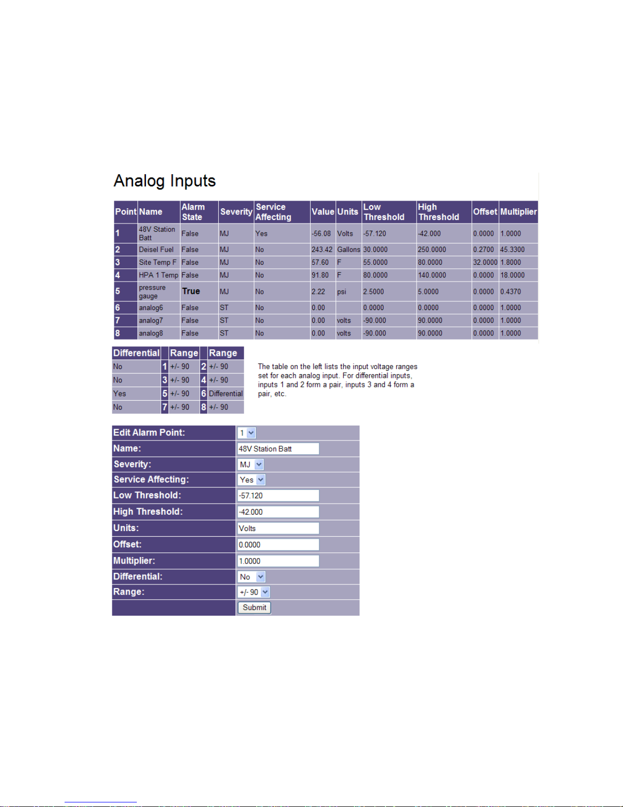
To provision or modify an analog input point, click the Analog Inputs link in the left pane. The Analog Inputs
page will appear, as shown in Figure 16. The Analog Inputs page displays three sections: the current
analog point settings section, the differential and voltage range settings section, and the edit alarm input
point dialog section.
Figure 16. Analog Inputs Page Via The Web
The Analog Inputs page current settings section displays provisioning information for the 8 analog inputs.
Each point is described by Analog Point number, Name, Alarm State, Severity, Service Affecting, Value,
Units, Low Threshold, High Threshold, Offset and Multiplier values.
Fial Incorporated 2314/2316-042315 19
Page 26

Model 2314/2316 SNMP Alarm Encoder
The middle table shows differential and range settings of the current configuration for any differential point
pairs, as well as the assigned voltage range for each analog input point. This tracks the changes you
SUBMIT on this page, but you must also SAVE & REBOOT for the changes to be implemented.
Use the edit analog point dialog section at the bottom of the screen to provision each analog point. This
dialog will not appear unless you are logged in as administrator.
To provision an analog input, edit the following fields:
Edit Analog Point: Use this drop-down box to select the Analog point you wish to edit.
Name: Enter a name for the selected Analog point. Any characters are allowed in this field.
Analog names can be the same as another Analog point; however, this is not recommended
for obvious reasons.
Severity: Select the Severity level for the selected Analog point. The possible Severity levels are:
CR, MJ, MN and ST. This indicates the seriousness of the alarm event occurring when the
value falls below the low threshold or rises above the high threshold.
Service Affecting: Select Yes if the selected alarm point is Service Affecting, or No if the selected
alarm point is Not Service Affecting when its value is outside the low and high thresholds. The
term ‘Service Affecting’ means that traffic has been dropped or that major communications
disruption has occurred.
Low Threshold: Enter the Low Threshold (most negative) value for the selected Analog point. If
the scaled Value is more negative than the Low Threshold, the Alarm State will be set to True.
This value is based on the converted input value after the offset and multiplier correction.
High Threshold: Enter the High Threshold (most positive) value for the selected Analog point. If
the scaled Value is more positive than the High Threshold, the Alarm State will be set to True.
This value is based on the converted input value, after the offset and multiplier correction.
Units: Enter the Units for the selected analog. Any characters are allowed in this field. An
example might be gallons, Volts, Amperes, gallons or dBm.
Offset: Enter the Offset for the selected analog point. The Offset is added to the raw analog
reading, and then multiplied by the Multiplier to calculate the Alarm Value. The offset is set in
measurement range units (Volts). Offsets are often used if a sensor yields a non-zero voltage
when the measured quantity is actually zero. Positive or negative offsets may be entered.
Suppose a sensor reports gallons of diesel fuel, and reads 1 volt for zero gallons, and 8 volts
for 600 gallons. Then an offset of minus 1 causes the range to become zero to 7 volts, and a
multiplier of 85.7 would yield values between zero and 600 gallons. You might also set the low
threshold to 50. Then you would get an alarm condition (and an SNMP notification) below 50
gallons.
20 2314/2316-042315 Fial Incorporated
Page 27

Model 2314/2316 SNMP Alarm Encoder
Multiplier: Enter the Multiplier for the selected Analog. The Offset is added to the raw Analog
measurement; the result is then multiplied by the Multiplier to calculate the Alarm Value.
Negative multipliers may be entered if you wish to reverse the sign or polarity of the value
measured.
Differential: Select Yes if the Selected Analog input is differential, or No if the selected Analog
input is single-ended. Single-ended measures the electrical potential between an analog input
pin and ground. Differential measures the electrical potential between a pair of pins,
irrespective of their relationship to ground. For differential inputs the pairing is fixed: Input 1 is
paired with input 2, input 3 with input 4, input 5 with input 6 and input 7 with input 8. Note that
this is different from a 2311 pairing of 1 with 9). You can have a mix of single-ended inputs
and differential-pair inputs in one unit.
Range: The analog input range is fixed at negative 90 volts to positive 90 volts. The inputs auto-
range and show values to two decimal digits of precision.
After all changes have been made, press the Submit button. The Submit button must be pressed to
register any changes made on this screen. You can submit changes from many screens before doing a
final Save & Reboot. To actually install the changes, click the Save & Reboot link on the left side and
confirm the request by entering the administrator name and password.
Note: As you submit changes, the entries in the alarm table will change, but the Value and Alarm State
columns will reflect pre-existing measurements settings currently in effect. You will not see your changes
reflected in the Value column until you save and reboot. In other words, you can change a multiplier from 1
to 1000 and units from Volts to millivolts, but the Value column will show a Volts reading obtained with the
original multiplier until you Save & Reboot.
The Boolean Alarms Page
Boolean (composite) alarm points are virtual alarm points created by combining the true/false states of
standard hardware alarm, status, analog and control points using Boolean operators (‘AND,’ ‘OR,’ ‘XOR’
and ‘NOT’). By combining hardware points this way, you can create an expression (a Boolean alarm) that
will be true if the true/false state of all of the individual points satisfy the expression. Note: Boolean alarm
points cannot include other Boolean points, only standard hardware points.
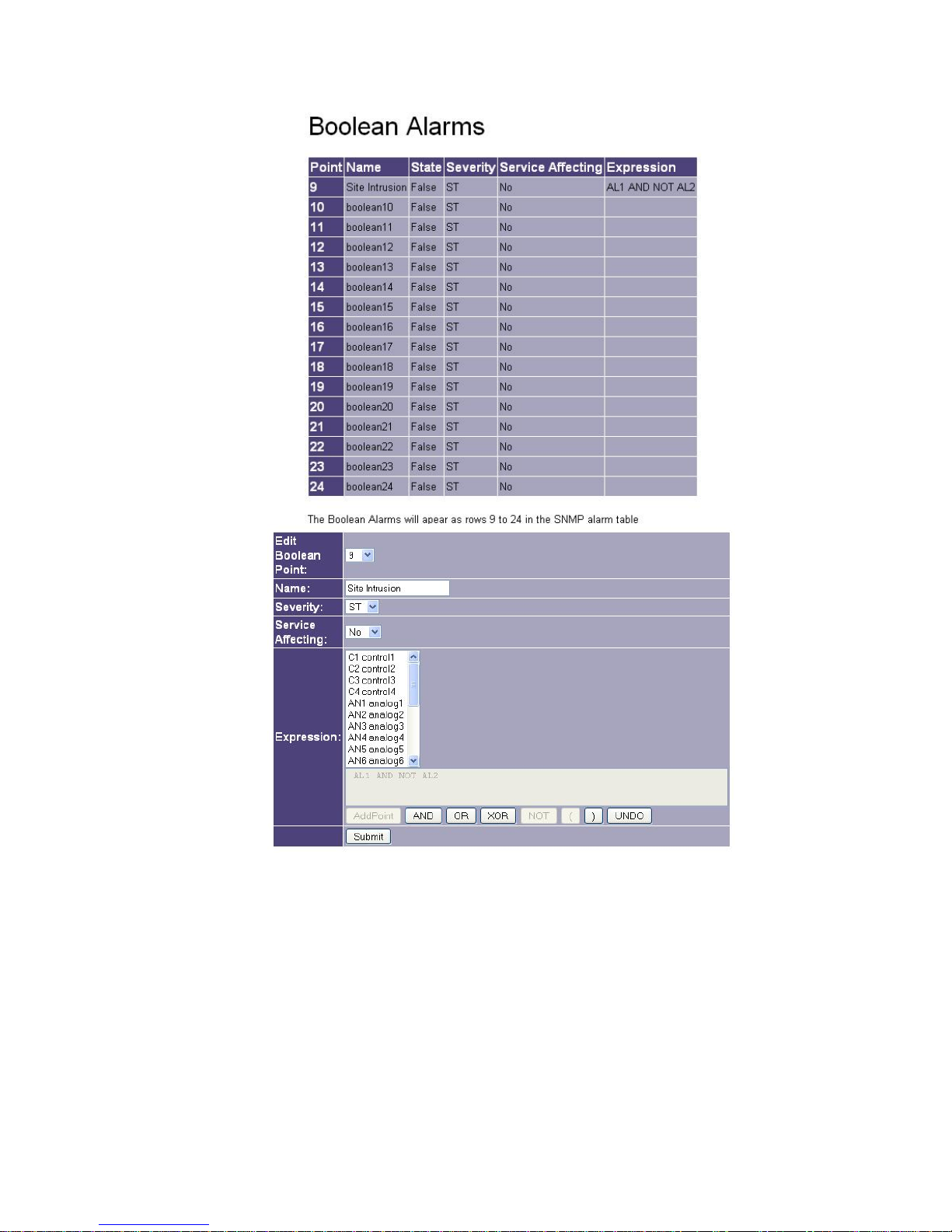
To provision or modify a Boolean point, click the Boolean Alarms link in the left pane. The Boolean Alarms
page will appear (see Figure 17), displaying a table of currently defined Boolean Alarms and an edit
Boolean Alar
m point dialog section.
Fial Incorporated 2314/2316-042315 21
Page 28
Model 2314/2316 SNMP Alarm Encoder
.
Figure 17. Boolean Alarms Page Via The Web
The top of the page displays a table listing the current provisioning information for up to 16 Boolean Points,
which are numbered 9 through 24. Boolean information includes Boolean Point Number, Name, the point’s
current State, Severity, Service Affecting and Expression.
Use the edit dialog at the bottom of the page to provision new or edit existing Boolean points. This edit
dialog will not appear unless you log in using the administrator login name and password. Note: If the point
already has an expression defined, you are only able to add additional items to the existing line or to UNDO
the last item.
22 2314/2316-042315 Fial Incorporated
Page 29
Model 2314/2316 SNMP Alarm Encoder
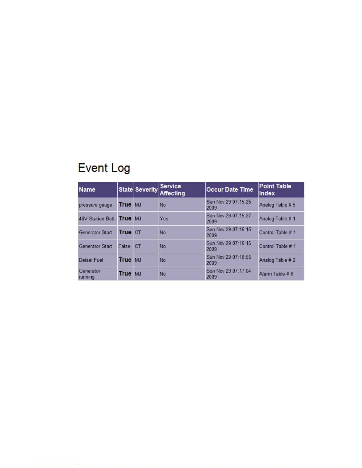
In the example above, if alarm point 1 is asserted (site door is open) and alarm point 2 is NOT asserted
(technician-at-site switch) then an intrusion alarm is activated. The door open alarm has a 10 second delay
on the alarm input page, so the technician has 10 seconds after opening the door to throw the ‘tech-at-site’
switch.
See Section 7 - Creating Boolean Alarm Points and Expressions on page 45 for detailed information on
creating Boolean Alarm points and expressions.
The Event Log Page
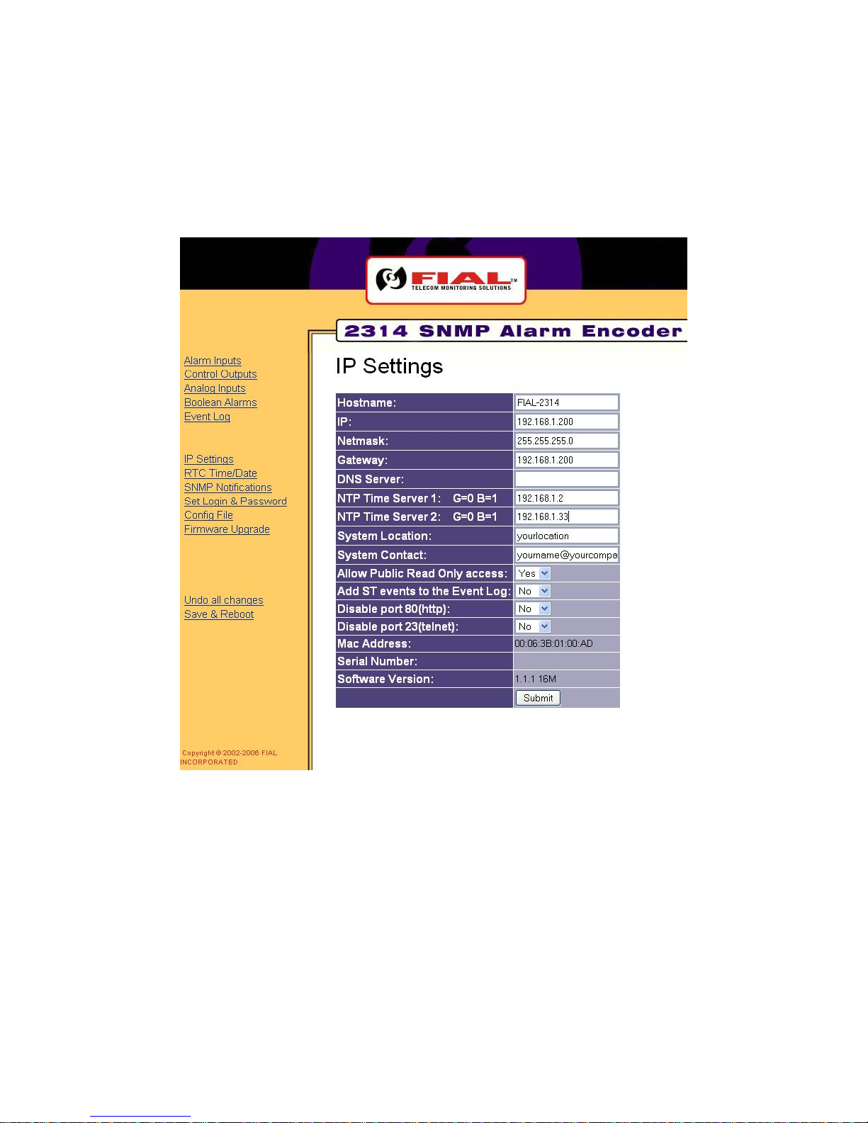
To view the Event Log, click the Event Log link in the left pane. The Event Log page will appear, as shown
in Figure 18. Each event listed also triggered an SNMPv2 notification (i.e. trap) to be sent to any SNMP
managers listed in the Notify Table.
Figure 18. Event Log Page Via The Web
The Event Log page displays a table listing the Alarm, Control, Analog and Boolean points that have
changed states and that have a Severity of CR, MJ or MN. If ‘Add ST events to the Event Log’ is set to Yes
in the IP Settings, then points with a Severity of ST are also shown in the Event Log. Event Log information
includes the point Name, State, Severity, Service Affecting, Occur Date Time and Point Table index.
The Point Table Index column indicates the type of event (Alarm, Control, Analog or Boolean) and the row
number in the corresponding static table.
Up to 100 Events (rows) can be stored in every SNMP Alarm Encoder. When the Event Log is full and a
new Event is added to the Event Log, the oldest Event is removed. In effect, the table scrolls upward. This
screen does not refresh automatically. When looking at the most recent items (bottom of table), click the
browser refresh button to see new events while maintaining the end of table position.
Fial Incorporated 2314/2316-042315 23
Page 30
Model 2314/2316 SNMP Alarm Encoder
The IP Settings Page
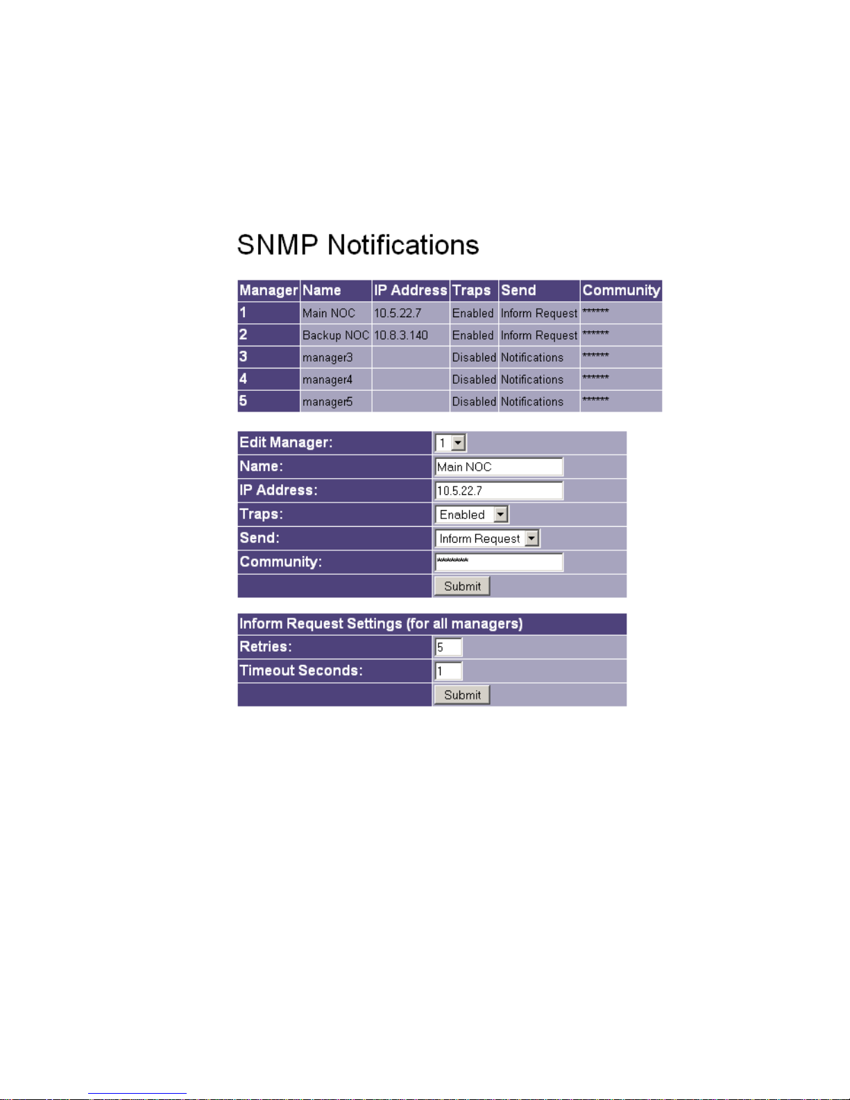
The IP settings, DNS Server address and NTP (or SNTP) Time Server address are provisioned in the IP
Settings page. To make changes, first click on the IP Settings link on the left side of the page. The IP
Settings page will appear, as shown in Figure 19 on the next page.
Enter new values for the following fields on the right-hand pane:
Hostname: Enter a host name for the device. A - Z, a - z, 0 - 9, and hyphen are the only
characters allowed. Twenty characters maximum. This name is reported as SNMP object
‘system.sysName.0.’
IP: Enter the IP address for this device. (See IP Address restrictions on page 41 for IP address
restrictions). The entry is checked for a properly formed value.
24 2314/2316-042315 Fial Incorporated
Figure 19. The IP Settings Page
Page 31

Model 2314/2316 SNMP Alarm Encoder
The default IP address for every SNMP Alarm Encoder is 192.168.1.200. At a minimum, you
must change the last three digits of the IP Address for all subsequent boxes. (Example:
192.168.1.201).
NOTE: Do not Save & Reboot after changing the IP address, Netmask or Gateway, until you
have made all other changes and verified them. Doing otherwise may render the device
inaccessible to you as a result of an IP settings change.
Recommended: Make all changes desired on the various web pages, then a single Save &
Reboot.
Gateway: Enter the gateway IP address for this device. Packets will be sent to the gateway if the
destination IP address does not match the IP address range (zone) for the device. The
gateway is usually a router that sends IP packets to their proper destination. The entry is
checked for a properly formed value.
Netmask: Enter the netmask for the device. The IP address and netmask are closely linked, and
must be determined by an IP network administrator or someone familiar with the IP address
mappings for the sites on your local area network (LAN). See NOTE 2 below for additional
netmask information.
DNS Server (optional): Enter the IP address for a Domain Name Server (DNS) on your network.
The DNS entry is only required if you enter hostname.domain instead of IP address in an NTP
Time Server entry. If you are not using an NTP Time Server to set the SNMP Alarm Encoder
time then you can leave this field empty.
NTP Time Server 1 (optional): Enter the IP address (or hostname.domain) for an NTP or SNTP
(Simple Network Time Protocol) server on your network. The SNMP Alarm Encoder can
automatically synchronize its system clock with the time server using UDP port 123. If you
enter hostname.domain you must also enter an IP address in the DNS Server field just above.
That DNS must be able to resolve the hostname to the proper IP address.
If you do not use a time server, the Encoder time and date must be set manually, and the time
may drift up to plus/minus 2.5 seconds per day.
The Primary Domain Controllers in Windows 2000 domains act as SNTP servers. Any
Windows 2000 Server can be instructed to act as a time-server. Many UNIX/Linux systems
use the xntpd program to serve NTP and SNTP requests. Use a time-server with a GPS (or
better) clock if you wish to have very accurate SNMP timestamps; or, set your time-server to
synchronize itself with a free stratum-1 or stratum-2 time-server on the Internet. The SNTP
network traffic for the 2314/2316 is extremely low. The data in the UDP synchronizing packet
is only 48 bytes long, sent and received once every 3 hours.
NTP Time Server 2 (optional backup time server): Same as above. If two time-servers are
entered, the Encoder only uses the one that continues replying. If that one later fails to reply,
the Encoder starts using the other unit, toggling between time-servers after each failure. After
a successful time update, three hours will elapse until the next check. After a failed update,
Fial Incorporated 2314/2316-042315 25
Page 32

Model 2314/2316 SNMP Alarm Encoder
one hour will elapse until the next check with the other time-server. However on startup, the
second time-server will be checked immediately if the first fails to respond.
The legends for each NTP Time Server contain data of the form: G=45 B=4. The G= counts
the number of normal time-server request/replies since startup. The B= counts the number of
requests that timed out or returned bad data. Note: If the first time-server is working normally
and the network drops very few IP packets, then the second time-server may not be used for
months or longer.
System Location (optional): Enter the location of this SNMP Alarm Encoder. Only letters,
numbers, dashes and spaces are allowed in this field (64 characters maximum). This value is
returned when a manager fetches the MIB-II value called ‘system.sysLocation.’
System Contact (optional): Enter the contact information for this SNMP Alarm Encoder. Only
letters, numbers, the @ sign, and spaces are allowed (62 characters maximum). Often a
telephone number or email address is used. This value is returned when a manager fetches
the MIB-II value called ‘system.sysContact.’
Allow Public Read Only access: Select Yes if this SNMP Alarm Encoder will allow SNMP Public
read access, or No if this SNMP Alarm Encoder will not allow SNMP Public read access. By
entering Yes, any host can fetch SNMP data using the community string public. The
community string public allows read-only access, no write access. If you select NO, then only
the mangers using one of the passwords listed under SNMP Notifications can read data from
the unit.
Add Status (ST) events to the Event Log: Select Yes if this SNMP Alarm Encoder will log ST
events, or No if this SNMP Alarm Encoder will not log ST events. CR (critical) MJ (major) and
MN (minor) events will always be logged. All events that are placed in the Event log will also
generate an SNMP v2 notification or inform request that will be sent to the SNMP managers
configured on the notify setup page.
MAC Address: All SNMP Alarm Encoders contain a factory-assigned MAC Address. The Media
Access Control (MAC) address is the network card address for the Ethernet port. It is a unique
number, different for every Ethernet network card ever manufactured and thus, cannot be
changed.
Serial Number: The serial number displays the FIAL factory serial number for the device. This
number cannot be changed.
Software Version: The software version number identifies the release or build version of the
firmware installed in the device. The user cannot change this number. The software version
may change if a TFTP firmware upgrade is performed.
26 2314/2316-042315 Fial Incorporated
Page 33

Model 2314/2316 SNMP Alarm Encoder
Once all changes have been made, press the Submit button. The Submit button must be pressed to
register any changes made on each screen. Changes are stored in a temporary file on the device, keyed
to your IP address. You can submit changes on many different screens before doing a final Save &
Reboot. To actually install the changes, the Save & Reboot link on the left side must be selected, and you
must confirm the request by again entering the administrator name and password. Others are thus
prevented from entering changes if you leave your desk. If you do not choose Save & Reboot, your
submitted changes will be erased after a few hours of inactivity.
After the unit reboots, you need not log in again unless you have restarted your Web browser. This is
because your Web browser still holds proper authentication keys. However, if you restart your Web
browser, you will have to login again. The SNMP Alarm Encoder does not store HTML ‘cookies’ on your
computer.
The RTC Time/Date Page
To modify the Real Time Clock (RTC), click the RTC Time/Date link in the left pane. The RTC Time/Date
page will appear, as shown in Figure 20.
Figure 20. RTC Time/Date Page Via The Web
The RTC Time/Date page (as shown in Figure 20), displays the current Date and Time of the RTC and the
System Clock.
Use the dialog table at the bottom of the screen to change the date and time. This entry table will not
appear unless you log in using the administrator name and password.
To set the RTC and the System Clock, edit the following fields:
Date MM: Enter the Month in this field. Only the digits 0-9 are allowed. The Month must be a
value between 1 and 12.
Fial Incorporated 2314/2316-042315 27
Page 34

Model 2314/2316 SNMP Alarm Encoder
Date DD: Enter the Day in this field. Only the digits 0-9 are allowed. The Day must be a value
between 1 and 31.
Date YYYY: Enter the Year in this field. Only the digits 0-9 are allowed. The Year must be a 4-
digit value.
Time HH: Enter the Hour in this field. Only the digits 0-9 are allowed. The Hour must be a value
between 1 and 23. UTC time is recommended. Note: Network Time Servers only provide
UTC (i.e. GMT) time.
Time MM: Enter the Minutes in this field. Only the digits 0-9 are allowed. The Minutes must be a
value between 1 and 59.
Time SS: Enter the Seconds in this field. Only the digits 0-9 are allowed. The Seconds must be a
value between 1 and 59.
After all changes have been made, press the Submit button. Pressing the Submit button will cause your
RTC clock changes to be instantly saved in the unit. For the most accurate result, press the submit button
about 1 second before the actual time you entered, to allow the transmission and processing delay. You do
not need to select Save & Reboot in order to change the time/date settings—the Submit button acts
instantly.
Most users will use UTC time for all alarm reporting devices. UTC is best for networks that span time
zones. Also, UTC does not suddenly change for daylight savings time. This unit will not perform a ‘daylight
savings time’ change. Such a change confuses many alarm managers and their reporting functions.
Note: It is useless to change the time and date if the unit is successfully using an NTP or SNTP Time
Server. The SNTP client will override your time and date settings (to match the Time Server’s) within a few
hours or so.
Note: To verify that the unit is successfully communicating with a time-server, see the IP Settings web
page. The G= # is the number of good time updates, and the B= # is the number of bad time updates. You
can also test the SNTP function. Change the time by 15 minutes or so, and then restart the unit (use Save
& Reboot on the web page screen). The time should automatically return to the correct time after the
restart is complete, if the provisioned time-server is reachable on the IP network.
28 2314/2316-042315 Fial Incorporated
Page 35
Model 2314/2316 SNMP Alarm Encoder
The SNMP Notifications Page
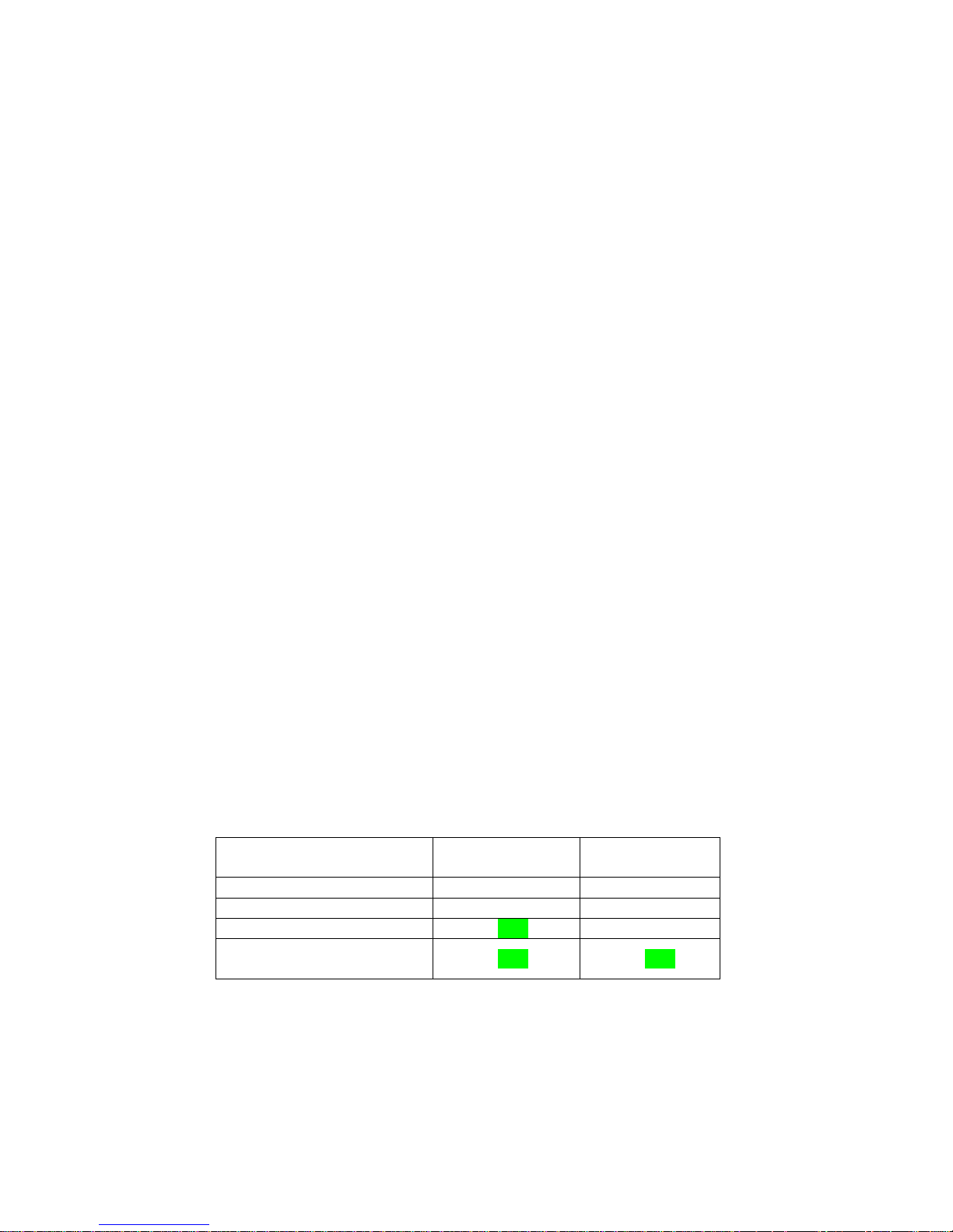
This screen configures the unit to send SNMP V2 notifications (called Traps in SNMP V1).
To specify or edit an SNMP Manager, click the SNMP Notifications link in the left pane. The SNMP
Notifications page will appear, as shown in Figure 21.
Figure 21. SNMP Notifications Page Via The Web
The SNMP Notifications page consists of three sections. The top section displays a table that lists the
provisioning information for up to five managers that can receive notifications and perform controls on this
unit. The 2314/2316 SNMP Alarm Encoder uses the manager’s IP address and the Community string to
validate a manager that is accessing it via SNMP commands. Only managers that are listed in this table
will have access to this unit via SNMP 'set' commands. Manager information includes manager table entry
Number, Name, IP Address, Traps (either enabled or disabled), Send (either Notification or Inform
Request) and Community string. The manager must also use the same community string as listed in this
table.
Use the dialog section in the middle of the page to provision each required manager. The SNMP
Notifications page will not even be listed unless you are logged in with the administrator password.
Fial Incorporated 2314/2316-042315 29
Page 36

Model 2314/2316 SNMP Alarm Encoder
To provision a Manager, edit the following fields:
Edit Manager: Use this drop-down box to select which of the five Managers you wish to edit.
Name: Enter a name for the selected Manager. Only letters, numbers, dashes and spaces are
allowed in this field. This name only helps to identify the manager and is present in the SNMP
notifications table. It is not used for any other purpose.
IP Address: Enter the IP address for the selected Manager. (See IP Address restrictions on page
41 for IP address restrictions).
Send: Select Notifications if the selected Manager will be sent SNMP v2 notifications (traps).
Select Inform Request if the selected Manager will be sent SNMP v2 inform requests.
Community: Enter the Community string (i.e. password) that the selected Manager will use to
access this unit via SNMP commands. A - Z, a - z, 0 - 9, and hyphen are the only characters
allowed. A manager must be using the IP address entered here as well as this Community
string in order to perform controls. Each manager can have a unique Community string value.
After all changes have been made, press the Submit button. The Submit button must be pressed to
register any changes made on this screen. You can submit changes from many screens before doing a
final Save & Reboot. To actually install the changes, click the Save & Reboot link on the left side and
enter the administrator login name and password to confirm.
Inform-Request Settings (for all managers):
The table on the bottom of the screen controls Inform-Request retries and timeouts. An SNMP
notification (trap) is an autonomous (automatic) message sent to a manager when an alarm
condition has occurred. An inform-request is basically a notification (trap) where the manager is
expected to reply and confirm that the manager has received the message. If the 2314/2316
SNMP agent does not receive the ‘inform’ within a certain time, the 2314/2316 SNMP agent will retransmit the same Inform-Request message again. The recommended Inform-Request retries
setting is 2. This yields a total of 3 attempts. The maximum setting is nine.
The recommended timeout seconds setting is 2 seconds. If you have network legs that transport
IP at low bit-rates, you may have to adjust this time upward. This is especially true if there are
several routers in a low bandwidth network that delay the packet by a full packet transmission time.
Most systems will use a value between 1 and 3 seconds.
The inform-request retries can be set between 1 and 9 retries. If you want zero retries, then use a
‘notification’ instead of an inform-request. A setting of ‘one’ means that two inform-requests will be
sent, unless the manager responds (confirms receipt) to the first inform-request before the Timeout
Seconds value. A ‘retries’ setting greater than 3 is probably a waste of network bandwidth and
resources.
30 2314/2316-042315 Fial Incorporated
Page 37
Model 2314/2316 SNMP Alarm Encoder
The inform-request feature helps improve performance for networks that are unreliable (dropped
packets). It cannot compensate for a manager that is shut down for a period of time. In that
situation, the manager is expected to poll the 2314/2316 SNMP Event Table to bring itself up to
date after the manager starts up. The 2314/2316 SNMP Event Table holds the last (most recent)
100 events. This typically covers a period of hours to days.
The 2314/2316 inform-request queue only processes one event at a time. If three reportable
events happen at about the same instant, the 2314/2316 will first do the notifications and all the
inform-request tries/retries for the first event. It will then process the second event, and so on.
Suppose you have two managers receiving inform-requests, and one is shut down. Informrequests to the ‘working’ manager may be delayed somewhat because of the retries to the
manager that is down. Suppose retries = 2 and timeout seconds = 2. After a fast sequence of
reportable events, the ‘working’ manager will have a wait of (3-tries * 2-seconds) = 6 seconds
between receiving inform-requests for successive events.
The 2314/2316 SNMP agent never sends notifications or inform-requests faster than one per
second. This avoids network congestion and resulting packet loss.
Note the two submit buttons on this web page. The upper submit button is used when changing
the parameters for a manager. The lower submit button is only used for setting the retries and
timeout values. Remember, you must do a ‘save & reboot’ operation for any ‘submit’ changes to
take effect.
A manager may set its Send Notifications column to True (1) or False (2) in order to turn its
notifications (or Inform-Requests) on and off.
If a manager is to receive Inform-Requests, then both columns (Send Notifications and Send
Inform-Requests) must be ‘True’. If a manager is to receive notifications, then the Send
Notifications column must be set to true and the Send Inform-Request column must be false. The
following table shows all possibilities:
Table 2. Notification/Trap and Inform Request Settings
Notification/Trap activity
Nothing sent False False
Nothing sent False True
Notifications sent True False
Inform-Requests
sent
To start/stop Notifications/Inform-Requests, a manager changes the value in the 2314/2316 MIB
using an SNMP ‘set’ command. The manager’s IP address and write community string must
match the values in the row being changed.
Fial Incorporated 2314/2316-042315 31
Send
Notifications
True True
Inform Request
Send
Page 38

Model 2314/2316 SNMP Alarm Encoder
After changing Inform-Request settings, press the Submit button. The Submit button must be pressed to
register any changes made on this screen. You can submit changes from many screens before doing a
final Save & Reboot. To actually install the changes, click the Save & Reboot link on the left side and enter
the administrator login name and password to confirm.
Web Browser interface - Logins and Passwords
There are three different web interface login types: Admin, Control and View. Each login type has its own
configurable login name and an associated password. Both login name and password are case sensitive.
Table 3. Login Names and Passwords
Login
Type
Admin
Factory default
login name
admin
Factory default
password
remote
Description
Allows provisioning and viewing of all settings in
the SNMP Alarm Encoder. Allows Save &
Reboot, Configuration download/upload, and
Firmware Upgrade. This user may also set
control points (relays) ON and OFF with the web
interface.
Control
control
remote
Allows viewing of all alarms, controls, Boolean
alarms and analog values via the web interface.
This user may also set control points (relays) on
and off with the web interface.
View
only
user
public
Allows viewing-only of alarms, controls, Boolean
alarms and analog values. No controls
permitted.
The factory default Administrator login (admin) and password (remote) for each device should be changed
for security reasons. The Control user password (and optionally the Control login name) should also be
changed; likewise, the View Only login name and password. To change the login names and passwords,
click the Set Login & Password link in the left pane.
32 2314/2316-042315 Fial Incorporated
Page 39
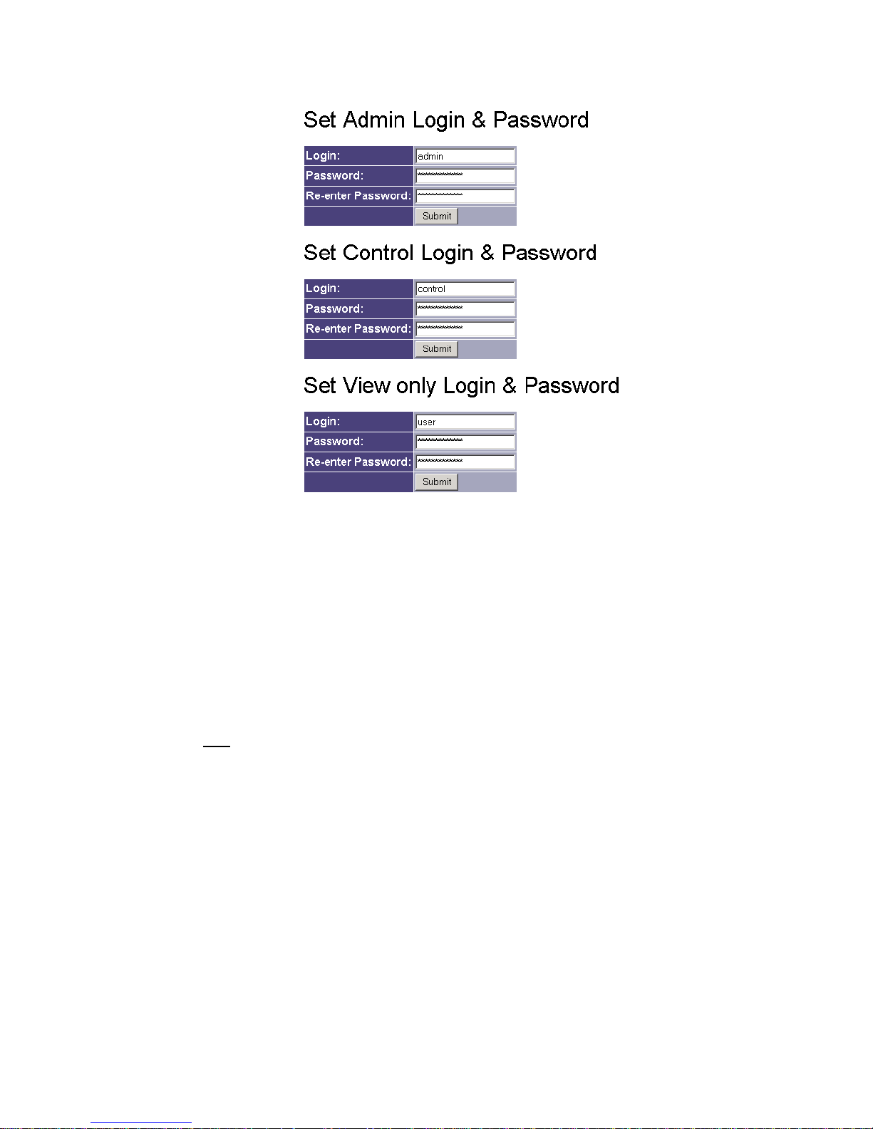
Model 2314/2316 SNMP Alarm Encoder
Figure 22. Set Login & Password Via The Web
To change the login and password, complete the following fields:
Login: Enter the new login name for the device.
Password: Enter the new password for the device.
Re-enter Password: Re-enter the new password for the device.
Remember that both
the login and password are case sensitive. A-Z, a-z, 0-9, and hyphen are the only
characters allowed for the login. The password can be any combination of characters, numbers and
special characters. Passwords should be longer than 8 characters in length.
After all changes have been made, press the Submit button. The Submit button must be pressed to
register any changes made on this screen. You can submit changes from many screens before doing a
final Save & Reboot. To actually install the changes, click the Save & Reboot link on the left side and
enter the administrator login name and password to confirm.
Fial Incorporated 2314/2316-042315 33
Page 40
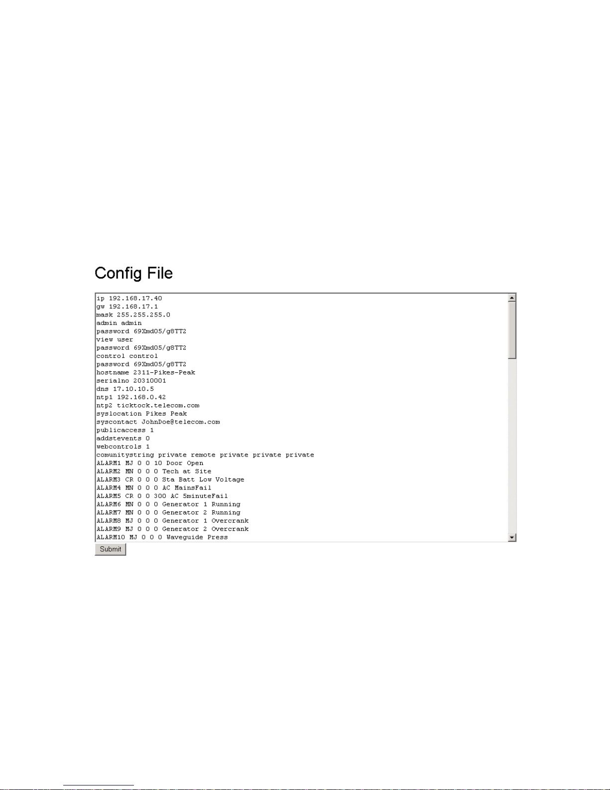
Model 2314/2316 SNMP Alarm Encoder
The Config File
The configuration file screen displays a text box of all current device settings. If you have ‘Submitted’
changes with the Submit button, the configuration file in Figure 23 will display those changes. However,
the revised data is not saved unless you perform a Save & Reboot. If you do not do a Save & Reboot,
your changes will be erased after a few hours, and you will be required to log in again. If you do not 'Save
& Reboot before you leave for a meeting, your 'submits' may be all undone. When someone resets a
remote unit you are provisioning before you save and reboot, you changes will be lost.
You can make changes to a SNMP Encoder’s configuration and ‘Submit’ them, then copy the resulting
configuration file for use in another unit – all without actually changing the original unit. You may undo your
session’s changes (back to the units ‘saved’ configuration) using the ‘Undo all Changes’ selection in the
left screen pane.
To save the contents of the Config File text box, click anywhere within the text area, and then press
control-a (control key and ‘A’ key together) to highlight all text. Follow this with a control-c (control key
and ‘C’ key together) to copy the text area to the operating system clipboard. Next, start up a text editor
(i.e. Notepad or WordPad), click anywhere within its text area, and do a control-v or a ‘paste text’
operation. Save the new file under an appropriate name for later use.
34 2314/2316-042315 Fial Incorporated
Figure 23. Configuration Text Screen
Page 41
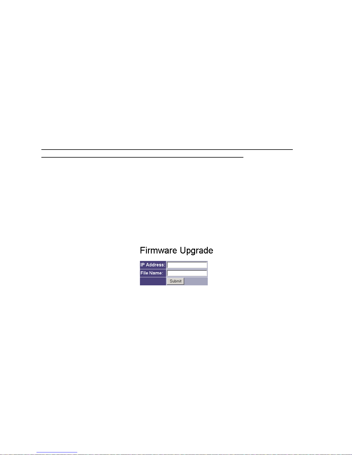
Model 2314/2316 SNMP Alarm Encoder
To upload a Config File, first open the saved file (created with NotePad or WordPad) with your text editor.
Click anywhere within the text area and type control-a to select all of it, and then type control-c to copy
the text to the clipboard. Erase the contents of the current Config File text box and paste in the contents of
the clipboard. Now, make sure to click the ‘Submit’ button at the bottom of the screen to register the
new configuration settings. When you upload and ‘submit’ a Config file, the IP address, netmask,
gateway, serial number and MAC address are not changed. This allows you to import a basic
configuration from another unit without losing the current IP address, netmask, gateway, serial number and
MAC address settings unique to each unit. You can make other last minute changes on the web pages
before the Save & Reboot. Finally, perform the Save & Reboot.
Never edit the Config File directly. There is an associated checksum saved with the Config File and there
is no way to make changes and re-enter the checksum manually.
Do not edit the saved configuration file on your computer because the checksum will become
invalid. The 2314/2316 will reject a configuration with an invalid checksum.
Firmware Upgrade
The program code (firmware) in the SNMP Alarm Encoder may be upgraded over the network. You must
set up a TFTP server on a Windows or a Unix/Linux machine. The configuration image file and an
associated checksum file must be placed in that TFTP directory. You then enter the IP address of the
TFTP server and the name of the configuration image file (currently fial23141.1.2_16m.cramfs for release
1.1.2 of the 2314, and fial23161.1.2_16m.cramfs for release 1.1.2 of the 2316). The file will be
downloaded into the unit, and will automatically program into the unit if the checksums are OK.
The unit will make two attempts to contact the TFTP server. If this fails, the SNMP alarm encoder will stop,
and reboot with the old firmware. Be sure the TFTP server is running and has the latest copies of the
following two files in its directory (fialXXXXn.n.n.cramfs and cksum_fialXXXXn.n.n.cramfs, where XXXX
is either 2314 or 2316, and n is a one or two digit number). Check the IP address and the File name
carefully before pressing the Submit button. Please see the notes section for additional information and
examples.
It is possible to run a TFTP server on any Windows machine, even a laptop machine. There are free
programs available to implement a Windows TFTP server. The following program by Ph. Jounin is
recommended: http://tftpd32.jounin.net/
Fial Incorporated 2314/2316-042315 35
Figure 24. Firmware Upgrade Via TFTP
Page 42
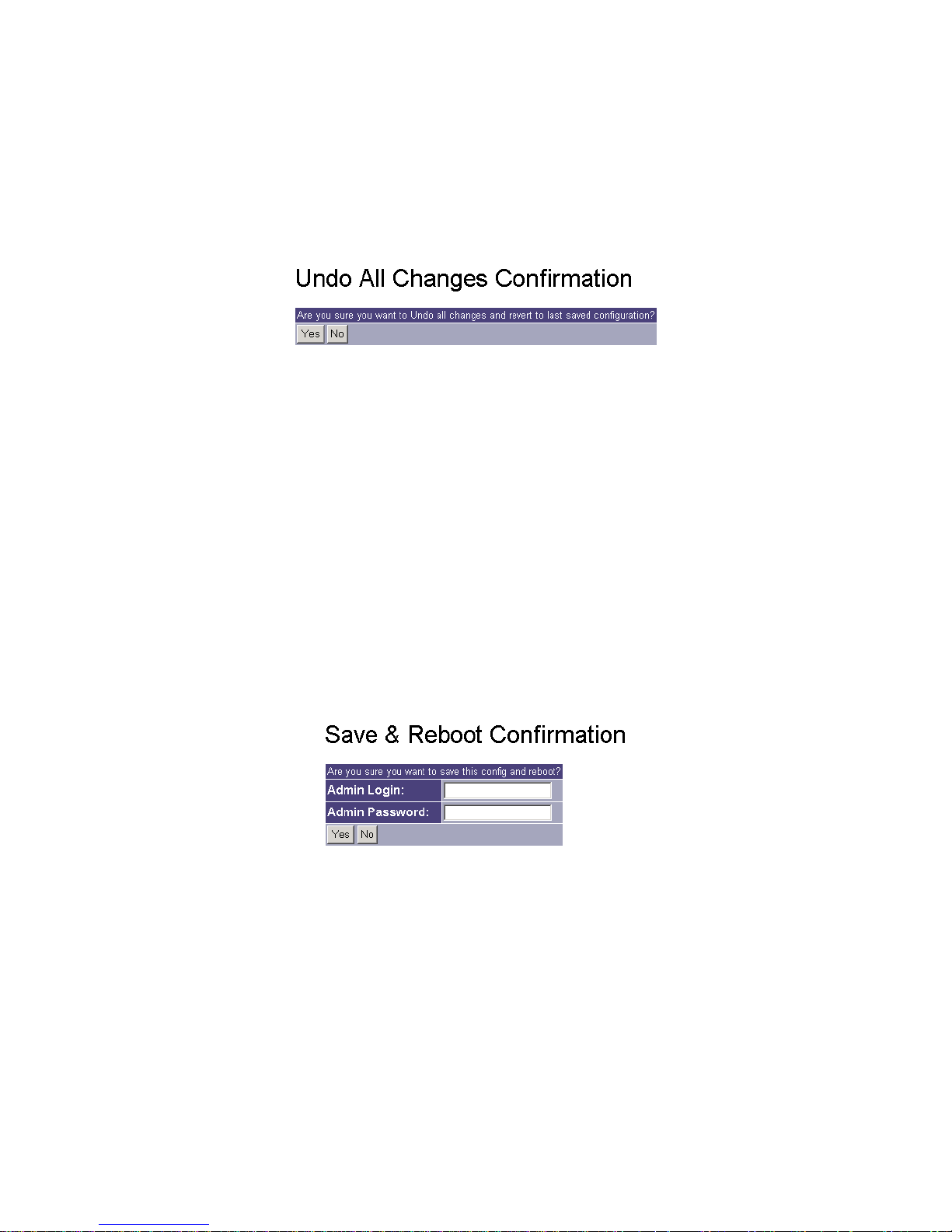
Model 2314/2316 SNMP Alarm Encoder
Undo All Changes
At times, you may wish to undo configuration changes already submitted. To undo these changes and
revert to the last saved settings, click the Undo All Changes link in the left pane. This will only work on
changes submitted during this login session, as long as you have not clicked the Save & Reboot button and
entered the appropriate name and password.
Figure 25. Undo All Changes Screen
When you undo your editing changes, it only affects ‘Submits’ you have made during this session. It does
not affect any other administrative user that has also made changes. Each administrative login gets its own
copy of the configuration file to change.
Save & Reboot
After all changes have been made, press the Save & Reboot link in the left pane. This link installs all of
the temporary changes stored each time the Submit button was pressed on the various screens. Confirm
the request by clicking YES when prompted. The reboot operation will turn OFF any controls (relays)
that are currently ON. Make sure that this will not cause any problems in your network.
Figure 26. Save & Reboot Screen
If you do not choose Save & Reboot, any submitted changes will be erased after a few hours of inactivity.
36 2314/2316-042315 Fial Incorporated
Page 43

Model 2314/2316 SNMP Alarm Encoder
5 Configuring the SNMP Master
In order for an SNMP manager to properly interrogate the 2314/2316 SNMP Alarm Encoder alarm, analog,
control, Boolean and event data, and to process any traps (notifications or inform requests), the SNMP
manager should have the Fial Incorporated Registry MIB and 2314/2316 Encoder MIB compiled into the
manager.
First, compile the Fial Incorporated registry MIB fial-registry-mib.mib into your SNMP manager, then
compile the 2314/2316 encoder MIB fial-enc-mib.mib. These MIBs are on a CD shipped with the
2314/2316 SNMP Alarm Encoder. If you do not have these MIBs, please contact Fial Incorporated
(www.fial.com) and they will be provided.
The 2314/2316 SNMP Alarm Encoder object data is contained in tables beginning at OID
1.3.6.1.4.1.4822.2.3.1. Walk or browse the encoder MIB to view the data. There are four main tables
storing the data, encEventLogTable (OID:1.3.6.1.4.1.4822.2.3.1.2), encAlarmPointTable
(OID:1.3.6.1.4.1.4822.2.3.1.3), encControlPointTable (OID:1.3.6.1.4.1.4822.2.3.1.4) and
encAnalogPointTable (OID:1.3.6.1.4.1.4822.2.3.1.5). All nodes are fully described within the MIB.
SNMP Notifications:
The 2314/2316 SNMP Alarm Encoder can report alarm and control events to SNMP managers
using SNMP v2 notifications. Up to five different SNMP managers can be sent notifications for
these events. Configuring the 2314/2316 notification table is explained in The SNMP
Notifications Page on page 29.
SNMP Controls:
Only managers provisioned in the 2314/2316 SNMP Notifications table are allowed to ‘set’ controls.
SNMP set requests from managers whose IP addresses are not present in the SNMP Notifications
table are rejected. Set requests are also rejected if the ‘write’ community string does not match
one of the strings in this table.
A set request must also contain the current spinlock value for the control point being set. The
spinlock value is a number managed internally by the 2314/2316 and associated with each control
point. A manager must first read (SNMP get) the current spinlock value for the target control point,
and then use that value in its set request. The spinlock value insures that only one manager at a
time manipulates a specific control point, and that the manager is informed of success or failure of
the set. The set request contains two variables: the spinlock and the requested state (on/off).
The following example assumes a 2314/2316 with an IP address of 192.168.1.200 and with the
Fial 2314/2316 SNMP Alarm Encoder MIBs compiled into your SNMP manager. Using your SNMP
manager, browse the 2314/2316 SNMP Alarm Encoder encControlPointTable (OID:
1.3.6.1.4.1.4822.2.3.1.4) to read the current spinlock values for the 16 control points (see Figure 27
below). Make sure the community strings match!
Fial Incorporated 2314/2316-042315 37
Page 44
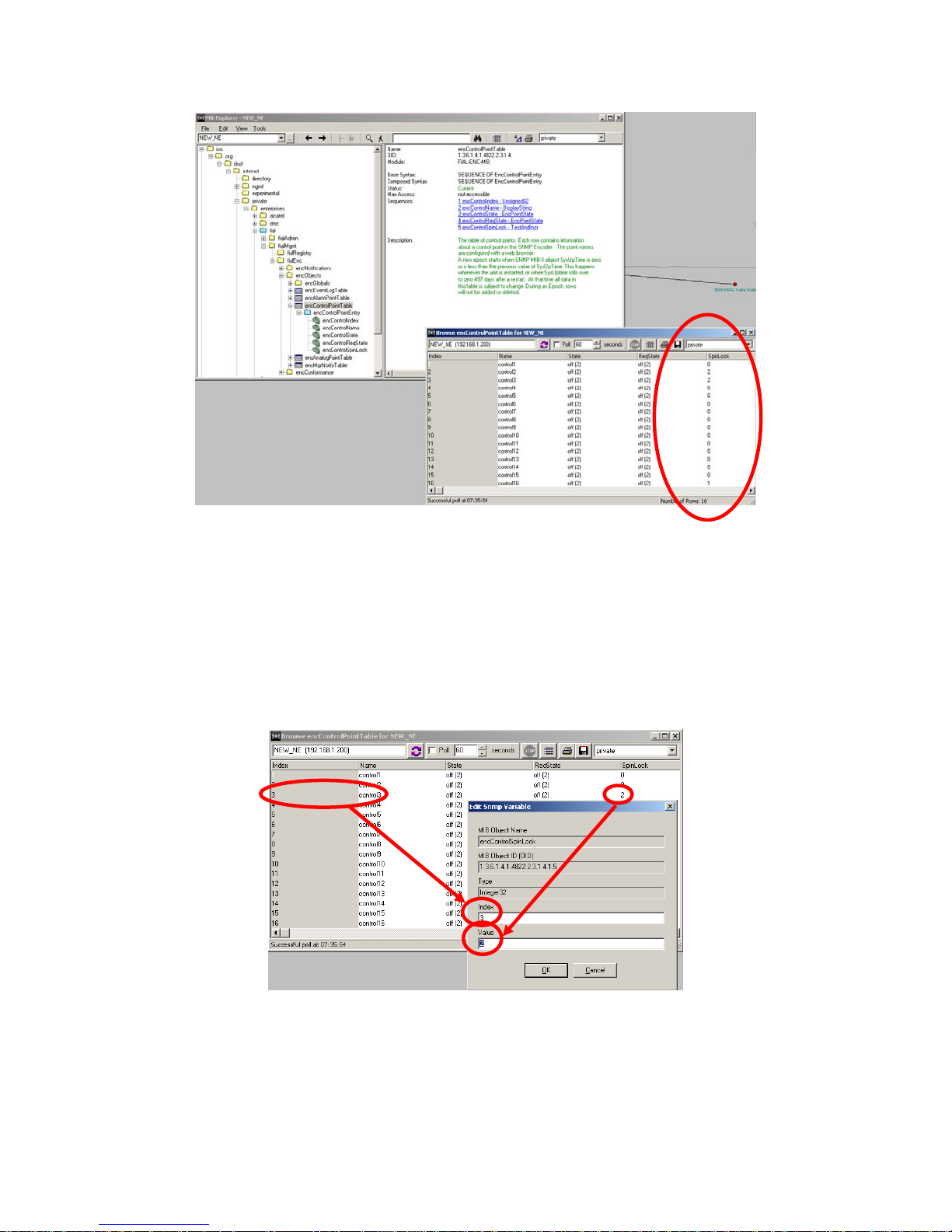
Model 2314/2316 SNMP Alarm Encoder
Figure 27. Browse encControlPointTable
Configure the first variable as the spinlock associated with the desired control point (relay). Select
the encControlSpinLock node (OID: 1.3.6.1.4.1.4822.2.3.1.4.1.5) and configure the variable (see
Figure 28). Enter the index of the spinlock that matches the index of the control point (point 3 in
this example) and set its value to match the current value of the spinlock (2 in this example).
Do the same for the requested control point state by selecting the encControlReqState node
(OID: 1.3.6.1.4.1.4822.2.3.1.4.1.4) and configuring this variable. Enter the same index of the
38 2314/2316-042315 Fial Incorporated
Figure 28. Setting Spinlock Variable
Page 45
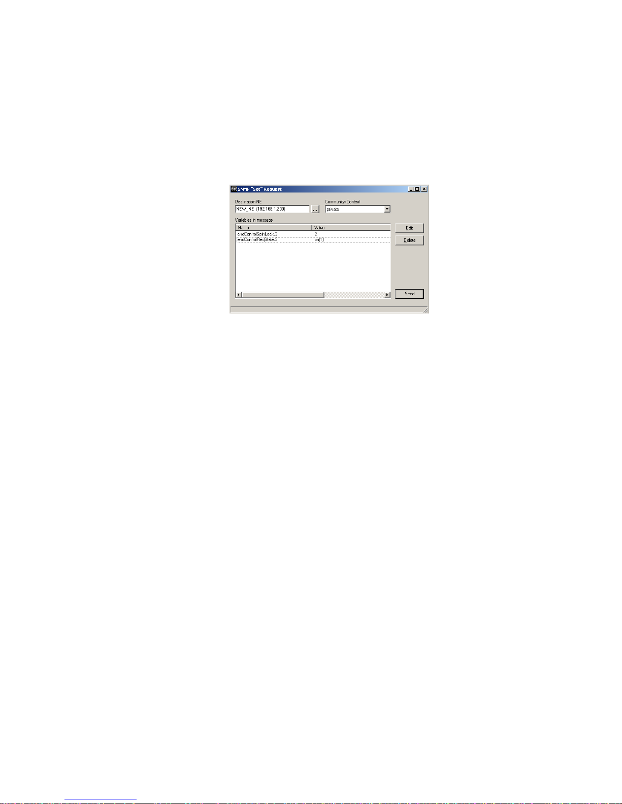
Model 2314/2316 SNMP Alarm Encoder
control point used for the spinlock above. Enter the requested control point state value as either
on(1) or off(2), as appropriate (on(1) in this example).
Now the completed Set Request (see Figure 29) contains the two variables entered above
(encControlSpinLock.3:2 and encControlReqState.3:on(1)) and is ready to be sent. Push the Send
button to initiate the set command.
Figure 29. Set Request with Spinlock and Control Point State Variables
Sending this Set Request will cause the 2314/2316 SNMP Alarm Encoder to execute the control
and change the on/off state of the control output relay to match the requested state (ON in this
example). The 2314/2316 then automatically increments the spinlock value for this control point.
Fial Incorporated 2314/2316-042315 39
Page 46

Model 2314/2316 SNMP Alarm Encoder
6 Notes
Web page provisioning caution
If two users are editing the configuration of an SNMP Alarm Encoder at the same time, the two users will
not see the changes ‘submitted’ by each other. A separate ‘changes’ buffer is created for each user. The
first user to Save & Reboot will have their changes applied. Any changes made by the second user will be
lost, and the second user will have to log in again and start over.
Remote Web or Telnet provisioning caution
If remotely provisioning the device, be careful not to enter an incorrect IP address, netmask or gateway
value. When you save and reboot, the device may become inaccessible to you. Be wary of changing IP
addresses, netmasks or gateway settings remotely. When you upload and ‘submit’ a config file, the IP
address, netmask, gateway, serial number and MAC address are not changed. This allows you to
import a configuration from another unit without losing the current IP address, netmask, gateway, serial
number and MAC address settings unique to each unit. All other settings in the config file will take effect
after you Save & Reboot.
The Craft interface can always be used to correct the IP address, netmask or gateway setting. You may
also change the administrator login name and password there. HyperTerminal is generally used with a
laptop computer to connect to the craft interface (On Unix/Linux, use minicom or equivalent). The Craft
interface parameters are: 9600-baud 8N1. Be sure that Flow Control is set to ‘none,’ in other words, no
handshaking. The craft terminal connections are on pins 4, 5 and 8 of the front panel Ethernet RJ45 . The
pin designations are in Table 8-2 At 9600 baud, the RS-232 cable should not be over 50 feet long.
Each telecommunications site generally has a specific range of IP addresses available, along with a
netmask and gateway (router) IP address suitable for the site. You may need to get that information from
your network administrator. No two devices at a site can have the same IP address. If this happens, one or
both devices will be inaccessible.
If you configure the SNMP encoder in your office, it may be best to leave the IP address, netmask and
gateway settings for last, after you have configured the device and verified your configuration. Set the finaldestination IP address, netmask and gateway as a last step, then Submit and Save & Reboot. The device
is now ready for installation at the remote site.
Hostname
The Hostname entry on the IP Settings screen allows device tracking by name instead of IP address. Enter
the hostname only, not the domain. The hostname must be a valid Internet hostname, for example:
Only a to z, A to A, 0 to 9 and hyphen are allowed.
Underscore is not allowed. Case is ignored.
Valid: 6Westlake-9 (host name can not start with a number)
Invalid: west_lake (underscore not allowed)
Invalid: west.lake (dot not allowed in host name)
Invalid: west-lake#95 (pound-sign not allowed)
40 2314/2316-042315 Fial Incorporated
Page 47

Model 2314/2316 SNMP Alarm Encoder
It is desirable to enter the assigned hostname and IP address into your network’s DNS server, so that users
and SNMP managers can refer to the SNMP Alarm Encoder by hostname.domain instead of using IP
address. If you use DHCP for all address assignments, then create a permanent lease for the IP address
assigned to the SNMP encoder. You will need to know the SNMP Encoder's MAC address to create a
permanent lease. The unit's MAC address is shown on the web page IP Settings screen, and looks
something like this: 00:06:3B:00:27:8C
Once your DNS is set up properly, if your domain name is something like ‘yourDomain.com’ and your
hostname is something like ‘pikespeak’, you can then enter ‘telnet pikespeak.yourDomain.com’ or
‘http://pikespeak.yourDomain.com’ instead of remembering IP addresses for each unit.
Note that there is no ‘www’ in this URL (web address).
IP Address restrictions
The first and last IP address in the range defined by the netmask cannot and must not be used. Netmasks
are used to divide the 4 billion possible IP addresses into smaller groups or “zones.” This is called subnetting.
For example: Given a netmask of 255.255.255.0, IP address n.n.n.0 and n.n.n.255 cannot be used. The
first is the network address, and the last is the network broadcast address. Commonly used netmasks, for
Class-C and smaller zones, are shown in the following table.
Table 4. Table of Netmasks and Addresses
Number of
Netmask
255.255.255.0 254 1 254 n.n.n.0 n.n.n.255
255.255.255.128 126
255.255.255.192 62
255.255.255.224*
*see example
below
255.255.255.240 14 16 14
255.255.255.248 6 32 6
255.255.255.252 2 64 2
Useable
Addresses
30 8 30
Number of
networks
2 126
4 62
Useable
addresses
per network
Addresses That Are Not Useable
n.n.n.0 n.n.n.127
n.n.n.128 n.n.n.255
n.n.n.0 n.n.n.63 n.n.n.64 n.n.n.127
n.n.n.128 n.n.n.191 n.n.n.192 n.n.n.255
n.n.n.0 n.n.n.31 n.n.n.32 n.n.n.63
n.n.n.64 n.n.n.95 n.n.n.96 n.n.n.127
n.n.n.128 n.n.n.159 n.n.n.160 n.n.n.191
n.n.n.192 n.n.n.223 n.n.n.224 n.n.n.255
n.n.n.0 n.n.n.15 n.n.n.16 n.n.n.31
n.n.n.32 n.n.n.47 etc.
n.n.n.0 n.n.n.7 n.n.n.8 n.n.n.15
n.n.n.16 n.n.n.23 etc.
n.n.n.0 n.n.n.3 n.n.n.4 n.n.n.7
n.n.n.8 n.n.n.11 etc.
Fial Incorporated 2314/2316-042315 41
Page 48

Model 2314/2316 SNMP Alarm Encoder
For example: If the IP address zone starts at 192.168.0.64, and the netmask is 255.255.255.224, then 32
addresses exist in the zone, from 192.168.0.64 to 192.168.0.95. However, the address ending in 64 is
never used for a host device, since it is the network address. Also, the address ending in 95 cannot be
used since it is the broadcast address for the zone. So, only the 30 addresses from 192.168.0.65 to
192.168.0.94 may be used. Most networks use the first or the last useable IP address in a zone (.65 or .94
in this example) for the gateway (router). If the destination IP address of an IP packet is not in a device's IP
address zone, then the packet is sent to the gateway. The gateway (router) 'knows' how to reach the other
addresses on the LAN or Internet. While it is common practice to assign the first or last useable address in
an IP address zone to the gateway device, this is not required.
Login & Password
A login (admin) and password (remote) is present in each SNMP Alarm Encoder shipped from the factory.
Remember that both the login name and password are case sensitive. The administrator login and
password will allow you to have access to the Craft port or telnet and web page configuration screens. For
security purposes, it is recommended that you change the login names and passwords of each device
installed to values known only to you or other administrators and trusted users.
If you forget the new administrator login name and password, the administrator login name and password
can be reset to the factory default. To do this, hold in the lamp test button after power-up or reset, until the
power-on function completes. This will take about 40 seconds. This will not change the IP address.
If the login/password page rejects your login, it is possible that someone has changed the login name
and/or password; or possibly your Caps Lock key is activated. Enter the correct user login name and
password, or see the directions above for restoring the factory default values.
Remember: Both login names and passwords are case sensitive.
Save & Reboot
For detailed information on Save & Reboot versus Submit, refer to the section Save & Reboot on page 36.
Web & UNIX Compatible Browsers
The web configuration pages use JavaSc
ript and Cascading Style Sheets. Microsoft Internet Explorer (IE)
version 6.0 or later is recommended. Firefox also works well. Netscape browsers must have JavaScript
enabled. This is not the same as Sun corporations ‘Java’ language. The Netscape 7.1 UNIX version does
not show the currently active login names for the control user and the view user. However, the proper login
names/passwords are submitted.
42 2314/2316-042315 Fial Incorporated
Page 49

Model 2314/2316 SNMP Alarm Encoder
Replacing the RTC Battery
The design lifetime for the RTC battery is 10 years. The battery is held in a holder and is easily
replaceable. Battery type BR2330 is used. Substituting a CR2330 will only last about 5 years due to
higher seal leakage.
Trivial File Transfer Protocol (firmware upgrade)
The 2314/2316 firmware upgrade consists of two files, and checksum file and a main file.
The checksum file is named: cksum_fial2314n.n.n.cramfs or cksum_fial2316n.n.n.cramfs
The main file is named: fial2314n.n.n.cramfs or fial2316n.n.n.cramfs
Where n.n.n is the firmware revision number. The current revision is 1.1.2, so the web page entry to start a
download of that file must be either: fial23141.1.2.cramfs or fial23161.1.2.cramfs.
The TFTP server (TFTPd32) must be downloaded and unzipped into its own directory. Put the two
firmware upgrade files in that same directory. Start the TFTP32.exe program. You will see a screen like
that shown below. Click on the settings button and un-check the DHCP server box, so it does not interfere
with other DHCP servers on your network. Then stop and restart TFTPd32.exe.
Be careful and double check the IP address and the filename you enter into the SNMP Alarm Encoder's
firmware update screen. Make sure the TFTP server program is running at that IP address and that it
contains the cksum_fialXXXXn.n.n.cramfs and fialXXXXn.n.n.cramfs files in the TFTPd32 program
directory. The unit will restart with the old firmware if it cannot contact the TFTP server or if the TFTP
server says it does not have the filename(s) requested by the 2314/2316. The craft interface (9600 8N1)
reports the progress of the TFTP transfers and any errors that occur.
When commanded to perform a firmware upgrade, the 2314/2316 resets and after 18 seconds it restarts
and begins the TFTP transfer of the cksum_fialXXXXn.n.n.cramfs file. That is a small file, so about one
second later the 2314/2316 asks for the fialXXXXn.n.cramfs file, which is about 1.6 Megabytes long.
Here are actual test results of upgrades over the Internet with a 256 kilobit/second connection at the
2314/2316 site and a 768 kilobit/second at the TFTP server, with 18 routers in between. The ping
turnaround time was 26 milliseconds. With little or no other traffic, the transfer took about 2 minutes,
averaging about 14,000 bytes per second. The 2314/2316 then takes an additional 45 seconds to flash the
new firmware and restart.
The slowest transfer seen was 36 minutes over the same Internet connection (256k to 768k connection),
with a very large TCP download on the 768 kilobit side at the same time. This caused encoder-to-TFTPserver ping-return times of 850 milliseconds and an average transfer rate of only 750 bytes per second.
The result of this slow 6000 bits per second firmware upgrade transfer took 36 minutes to complete, but the
new firmware was loaded successfully. In this situation though, timeouts and retries caused the TFTP
server to show messages like the following in its activity screen:
Ack block 521 ignored (received twice)(06/05 17:19:14.896
Ack block 543 ignored (received twice)(06/05 17:19:30.268
Fial Incorporated 2314/2316-042315 43
Page 50
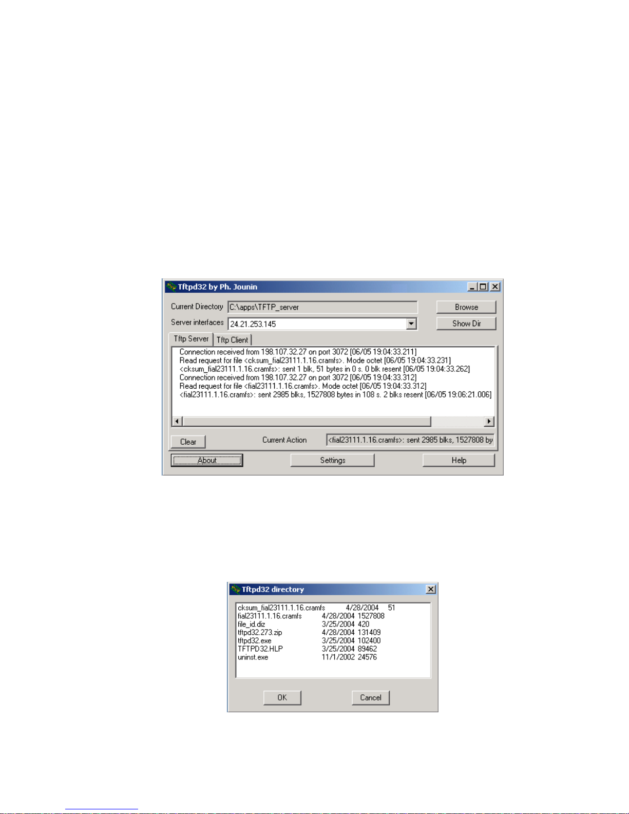
Model 2314/2316 SNMP Alarm Encoder
When the firmware update starts, the TFTP client makes two attempts to contact the server with an interval
of 4 seconds. If the server does not respond, the 2314/2316 will stop until it is physically reset. Since the
download requests are UDP packets, there is a chance that they may both be lost in a very busy network or
in a degraded network. If the network is very poor, it may be necessary to visit the site of the 2314/2316 to
do the firmware update. A laptop should be loaded and tested with the TFTPd32 server program before
leaving for the remote site. We have had no problems with the TFTPd32 server running on Windows
2000/2003. TFTPd32 is recommended by Cisco, HP and other major companies.
TFTP Server (TFTPd32 by Ph. Jounin) main screen after successful download. This is a model 2311
download, the model 2314/2316 will be similar:
Figure 30. TFTP Server Window
TFTP Server directory (Show Dir button), including the two fial2311 firmware files for firmware
version 1.1.16:
Figure 31. TFTP Server Directory Window
44 2314/2316-042315 Fial Incorporated
Page 51
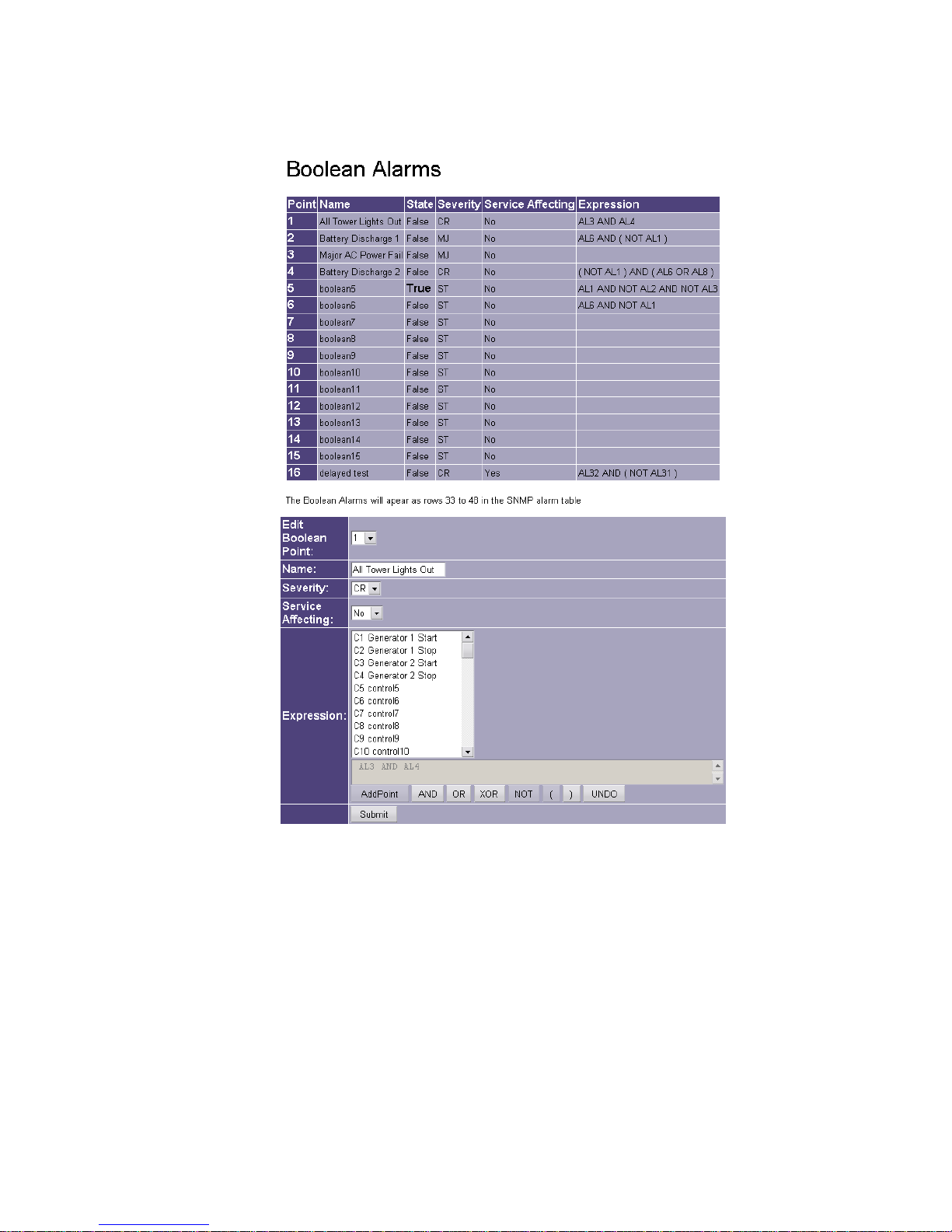
Model 2314/2316 SNMP Alarm Encoder
7 Creating Boolean Alarm Points and Expressions
To provision a Boolean Alarm point, edit the following fields in the edit dialog at the bottom of the Boolean
Alarms screen:
Edit Boolean Point: Use this drop-down box to select the Boolean point you wish to edit.
Name: Enter a name for this selected Boolean point. Any characters are allowed in this field. Two
Boolean points can have the same name; however, this is not recommended for obvious
reasons.
Fial Incorporated 2314/2316-042315 45
Figure 32. Boolean Alarms Screen
Page 52

Model 2314/2316 SNMP Alarm Encoder
Severity: Select the Severity level for the selected Boolean point. The possible Severity levels are:
CR, MJ, MN, and ST.
Service Affecting: Select Yes if the selected Boolean point is Service Affecting, or No if the
selected alarm point is Not Service Affecting.
Expression: Use the list box and buttons along the bottom to build a Boolean expression.
Entering an expression creates a new alarm point whose state depends on specified
combinations of other alarms. You create expressions using the true/false state of any alarm
point, status point, control point or analog point, combined in various ways with the true/false
state of one or more additional alarm, status, control or analog points. A built-in Boolean
expression checker helps enforce the correct syntax.
Note: An analog point is ‘true’ (asserted) only if the current value exceeds the high or low
threshold setting for that point.
Alarm and control point names can be quite long. The maximum length of an expression is
128 characters. A pop-up box will warn you when reaching that limit. Therefore, abbreviations
are automatically used within the Boolean expression when the expression is created. The
appropriate point number is appended to the abbreviation. Alarms are signified by the
abbreviation “AL” (AL1 to AL8), Controls are signified by the abbreviation “C” (C1 to 4) and
Analog alarms by the abbreviation “AN” (AN1 to AN4).
The simplest example of a Boolean Alarm is one that depends on the combined state of two
points. If you want a Boolean Alarm to be asserted when both hardware points are asserted,
just AND them together. For example, suppose there are two predefined alarm points, named
“Tower Beacon” (AL3) and “Tower Side Light” (AL4). You want to create a new Boolean
Alarm point (#1) that is asserted when both AL3 and AL4 are asserted.
Start by selecting the desired point number from the Edit Boolean Point drop-down list (select
#1 for this example). This will typically be an unused point number. Enter a descriptive name
for the new point, something like “All Tower Lights Out.” Note: Only alphanumeric and space
characters are allowed. Enter the correct Severity level and Service Affecting state for the new
Boolean Alarm point in the corresponding boxes. In this example change the Severity to “CR”
and leave the Service Affecting state at “No.”
Next, build the expression. Select the first point for the expression from the scrollable point list
box (see Figure 33). You may need to use the thumb-bar to get to the desired point. In this
example select “AL3 Tower Beacon.” N
otice that the point abbreviation is listed for alarm
point #3 before the point name. With the correct point selected, click on the AddPoint button
at the bottom of the dialog screen. Notice that the point abbreviation (AL3) has been added to
the expression field (gray area at the bottom of the dialog) as shown in Figure 33. Only
function and operator buttons that are appropriate for the next entry in the expression are
enabled after each entry is made (light gray and able to be highlighted). Notice that you can
now only select from the AND, OR, XOR,) and UNDO buttons for the next entry.
46 2314/2316-042315 Fial Incorporated
Page 53
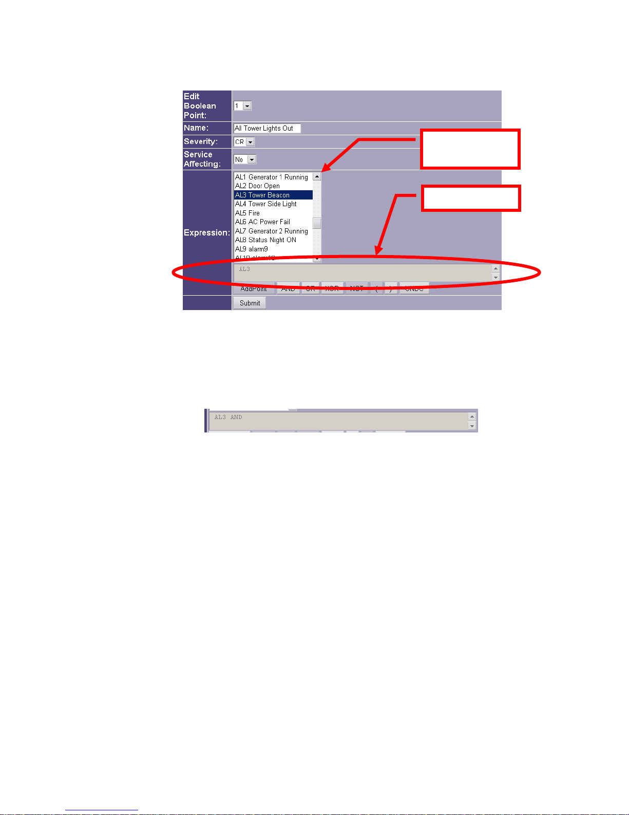
Model 2314/2316 SNMP Alarm Encoder
Scrollable Point
List Box
Expression Field
Figure 33. First point in Boolean Expression
Since we want to combine two asserted points, we need to click on the AND button next. This
adds the AND operator to the expression (see Figure 34).
Figure 34. Partial Simple AND Expression
Now add the final point to the expression by going back to the scrollable point list box and
selecting “AL4 Tower Side Light.” Press the AddPoint button to add the final point to the
expression. The expression now should read: “AL3 AND AL4” (see Figure 35).
Fial Incorporated 2314/2316-042315 47
Page 54
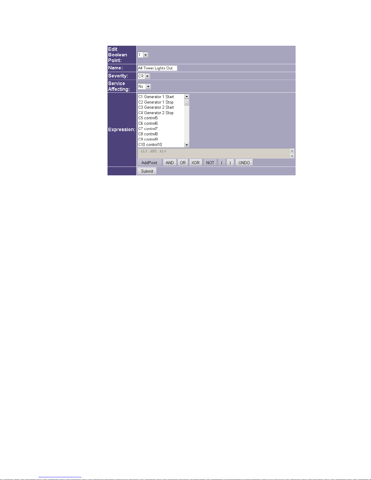
Model 2314/2316 SNMP Alarm Encoder
Figure 35. Completed Simple AND Expression
After all changes have been made, press the Submit button at the very bottom of the Boolean
Alarms page. The Submit button must be pressed to register any changes made on this
screen. To actually install the changes, you must click the Save & Reboot link on the left side
and confirm the request by entering the administrator name and password.
The next example is a Boolean Alarm that depends on the state of two alarm input points, but
with one that is in its unasserted (NOT asserted) state. The NOT operator inverts the
true/false asserted state of the selected point. Suppose that there are two predefined alarm
points. One is named “AC Power Fail” (AL6) and the other is named “Generator 1 Running”
(AL1). “AC Power Fail” is asserted whenever AC power is lost, while “Generator 1 Running” is
asserted whenever the generator is running. You want to create a new Boolean Alarm point
(#2) that is asserted when AC power is lost (AL6 asserted = true), but only if the generator is
not running (AL1 unasserted = false).
Start by selecting the desired point number from the Edit Boolean Point drop-down list (#2 for
this example). Enter a descriptive name for the new point, something like “Battery Discharge
1.” Enter the correct Severity level and Service Affecting state for the new Boolean Alarm point
in the corresponding boxes. In this example, change the Severity to “MJ” and leave the
Service Affecting state at “No.”
48 2314/2316-042315 Fial Incorporated
Page 55
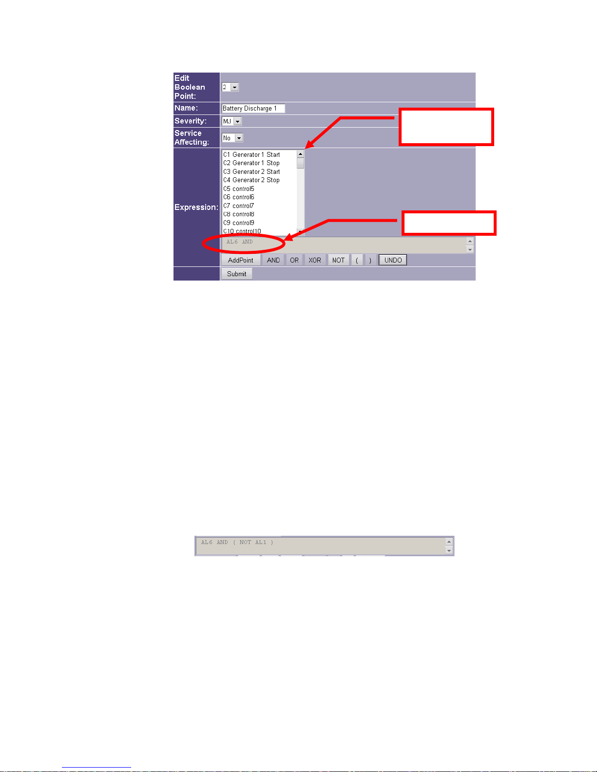
Model 2314/2316 SNMP Alarm Encoder
Scrollable Point
List Box
Expression Field
Figure 36. Second Boolean Example
In the scrollable point list box, select the first point for the expression. In this example, select
“AL6 AC Power Fail.” Remember that you may have to use the thumb-bar to access the
desired point. With the correct point selected, click on the AddPoint button at the bottom of
the dialog screen. Click on the AND button next. Notice that the point abbreviation (AL6) and
the AND operator have been added to the expression field (see Figure 36).
Now, to add an unasserted point (unasserted = false) to the expression we need to use the
NOT operator. It is always a good idea to enclose various parts of an expression within
parentheses to make sure they are evaluated in the correct order and for easier understanding
of the expression. To do this, click on the open-parenthesis ( button, then click on the NOT
operator button. The expression field should now read: “AL6 AND ( NOT.” Add the second
point in the expression for this example by selecting “AL1 Generator 1 Running” from the
point list box and clicking on the AddPoint button. Finish the expression by clicking on the
close-parenthesis ) button (see Figure 37).
Figure 37. Completed Unasserted Condition Expression
After all changes have been made, press the Submit button to register the settings and click
the Save & Reboot link on the left side to save the changes if you are done with creating and
editing Boolean Alarms.
Use the OR operator to combine two points such that the true/false state of either one causes
the expression to evaluate to TRUE. For example, suppose you want a Boolean Alarm to be
Fial Incorporated 2314/2316-042315 49
Page 56
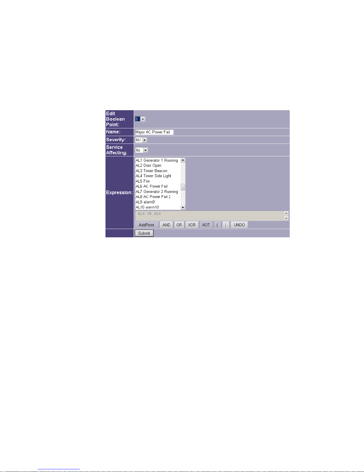
Model 2314/2316 SNMP Alarm Encoder
generated if either one of two point states are true (in this case asserted). Assume there is
another alarm point named “AL8 AC Power Fail 2” for this example. Perform the point
creation and main settings as done for the previous examples, but this time use the OR
operator to combine the two points. Name the Boolean point “Major AC Power Fail“ with a
Severity level of MJ. Select “AL6 AC Power Fail” and “AL8 AC Power Fail 2” as the two
points to be OR’d together. The expression should simply read “AL6 OR AL8” when finished.
Figure 38. Simple OR’d Expression
We can also change the order of evaluation of an expression by using parentheses. Multiple
points and conditions almost always need parentheses to make sure the expression is
evaluated as intended. In this example, suppose you want to create a fourth Boolean Point
that is asserted only if the station battery is discharging because a generator is not running and
either one of two AC power sources have failed. To insure the proper order of evaluation of
the points, use the parentheses to logically group the points together.
For this example, create a new point by selecting point #4 from the Edit Boolean Point dropdown list. Enter a point name of “Battery Discharge 2,” a Severity of “CR” and “No” for the
Service Affecting state in the corresponding boxes. Since we want the unasserted state for
this first point, start by clicking on the open parenthesis ( button, then the NOT operator button.
The expression should read: “( NOT.” Next, select “AL1 Generator 1 Running” from the
scrollable point list box, press the AddPoint button, then click on the close parenthesis )
button. The expression should now read: “( NOT AL1 ).” We need to add another condition to
the expression, so press the AND button. The expression now reads: “( NOT AL1 ) AND.”
The next part of the expression combines two alarm points. This is done with the OR operator
and enclosing this part of the expression within parentheses. We want to create a true
condition if either one of these two points is asserted (true). Start by clicking on the open
50 2314/2316-042315 Fial Incorporated
Page 57
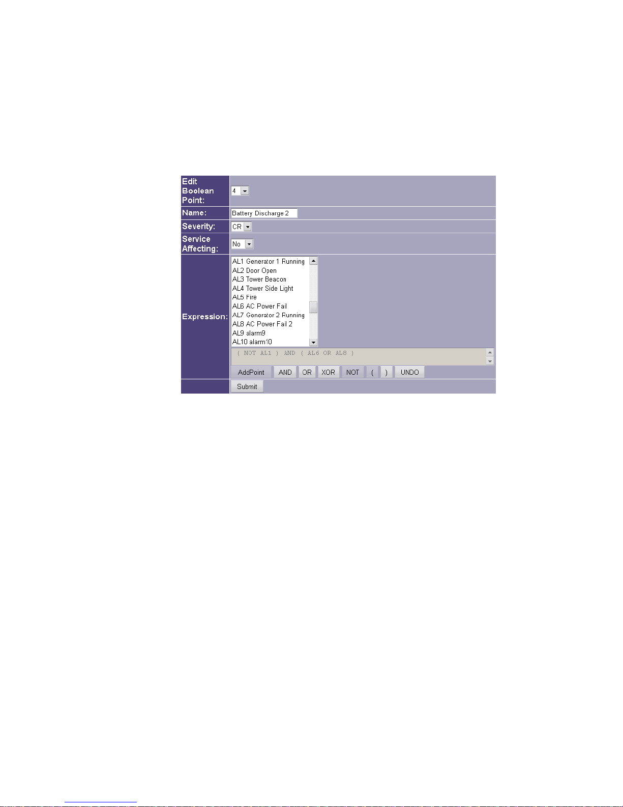
Model 2314/2316 SNMP Alarm Encoder
parenthesis ( button to enclose the OR condition of the two points. Select alarm point “AL6 AC
Power Fail” from the list box, then press the AddPoint button. Next, click on the OR operator
button. Select the second alarm point “AL8 AC Power Fail 2” from the point list box and again
press the AddPoint button. Finally, press the close parenthesis ) button to finish the
expression (see Figure 39).
Figure 39. Creating a Complex Boolean expression
This expression will assert the Boolean Alarm point only if alarm point 1 is unasserted
(false) and either alarm point 2 or alarm point 3 are asserted (true).
The current expression is always displayed in the gray area between the point list and the
buttons. Expressions cannot be edited, other than with a simple Undo operation. Pressing
the Undo button simply removes the last item in the expression. You can keep removing
the last item until you get to the point in the expression you want to change, then enter the
correct item and re-enter the remaining operators and points to finish the expression.
Remember to press the Submit button after all changes have been made. The Submit button
must be pressed to register any changes made on this screen. You can submit changes from
many screens before doing a final Save & Reboot. To actually install the changes, click the Save
& Reboot link on the left side and confirm the request by entering the administrator name and
password.
Fial Incorporated 2314/2316-042315 51
Page 58

Model 2314/2316 SNMP Alarm Encoder
8 I/O Connector Pin Designations
Left Column: 50-pin CHAMP (AMP) front-panel connector
Right Column: 66M Block pins numbered top to bottom (not the telco pairing/numbering)
Table 5. 2314/2316 I/O Connector Pin Assignment
AMP
50-pin
26 Alarm Input 1
1 Alarm Input 2
27 Alarm Input 3
2 Alarm Input 4
28 Alarm Input 5
3 Alarm Input 6
29 Alarm Input 7
4 Alarm Input 8
30 Alarm Input 9 (2316)
5 Alarm Input 10 (2316)
31 Alarm Input 11 (2316)
6 Alarm Input 12 (2316)
32 Alarm Input 13 (2316)
7 Alarm Input 14 (2316)
33 Alarm Input 15 (2316)
8 Alarm Input 16 (2316)
34 Station Gnd (Alm)
9 Station Gnd (Alm)
35 Analog Input 1
10 Analog Input 2
36 Analog Input 3
11 Analog Input 4
37 Analog Input 5
12 Analog Input 6
38 Analog Input 7
Connection 66
Block#
1
2
3
4
5
6
7
8
9
10
11
12
13
14
15
16
17
18
19
20
21
22
23
24
25
AMP
50-pin
13 Analog Input 8
39 Analog Ground 27
14 Analog Ground 28
40 +5 Volts for sensors
15 Expansion 1
41 Expansion 2
16 Expansion 3
42 Spare
17 Station Ground 34
43 Relay 1 N.O.
18 Relay 1 Common
44 Relay 1 N.C.
19 Relay 2 N.O.
45 Relay 2 Common
20 Relay 2 N.C.
46 Relay 3 N.O.
21 Relay 3 Common
47 Relay 3 N.C.
22 Relay 4 N.O.
48 Relay 4 Common
23 Relay 4 N.C.
49 Summary N.O.
24 Summary Common
50 Summary N.C.
25 Station Ground 50
Connection 66
Block#
26
29
30
31
32
33
35
36
37
38
39
40
41
42
43
44
45
46
47
48
49
See the 66M Block cut-out sheet at the end of
this manual for 50-pin to 66 block pin-outs.
52 2314/2316-042315 Fial Incorporated
NOTE: The summary relay N.O contact closes
due to any alarm of CR, MJ, or MN severity. An
alarm of ST (status) severity will not close this
relay.
Page 59
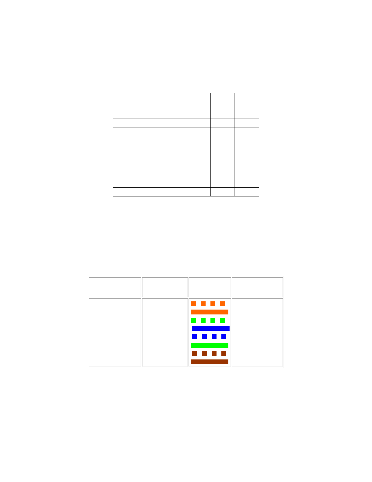
Model 2314/2316 SNMP Alarm Encoder
9 ETHERNET CONNECTOR (RJ-45 JACK)
Table 6. Ethernet Connector Pin Assignments
Signal Name RJ-45
pin #
DB9
pin #
TX data + 1
TX data - 2
RX data + 3
RS232 RX data
4 2
Encoder to PC COM port
RS232 TX data
5 3
from PC COM port to Encoder
RX data - 6
N.C. 7
RS232 Ground 8 5
Note: Hold the cable in your hand with the RJ-45 connector pointed away from you (with the hook/tab
underneath). Looking at the cable and pins you may see the following on some clear RJ-45 connectors,
from left to right. Note that one pair (green in the example below) is always split between pins 3 and 6.
Table 7. Straight-Through Ethernet Cable Wiring (T-568B Color Code)
Pin 1 TX data +
Pin 2 TX data -
Pin 3 RX data +
Pin 4
Pin 5
Pin 6 RX data -
Pin 7
Pin 8
COLOR
CODE
White/orange
orange
white/green
blue
white/blue
green
white/brown
brown
COLOR
Pin 1 TX data +
Pin 2 TX data -
Pin 3 RX data +
Pin 4
Pin 5
Pin 6 RX data -
Pin 7
Pin 8
A regular Ethernet cable will have both ends wired as in Table 7.
Fial Incorporated 2314/2316-042315 53
Page 60
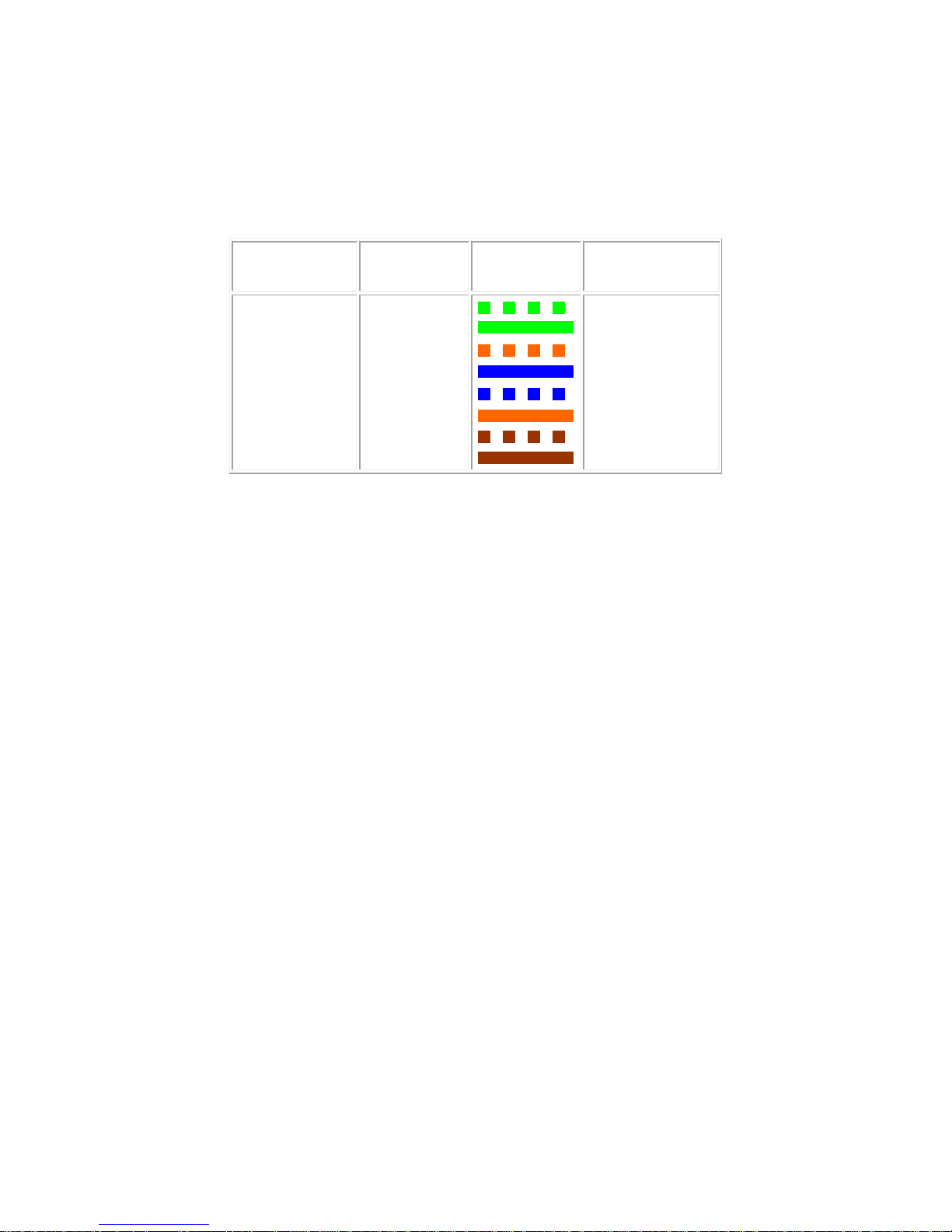
Model 2314/2316 SNMP Alarm Encoder
A cross-over Ethernet cable will have one end wired as in Table 7 and the other end wired as in
Table 8.
Table 8. Cross-Over Ethernet Cable Wiring - opposite end
Pin 1 RX data +
Pin 2 RX data -
Pin 3 TX data +
Pin 4
Pin 5
Pin 6 TX data -
Pin 7
Pin 8
COLOR
CODE
White/green
green
white/orange
blue
white/blue
orange
white/brown
brown
COLOR
Pin 1 TX data +
Pin 2 TX data -
Pin 3 RX data +
Pin 4
Pin 5
Pin 6 RX data -
Pin 7
Pin 8
54 2314/2316-042315 Fial Incorporated
Page 61

Model 2314/2316 SNMP Alarm Encoder
10 2314/2316 Remote Encoder Specifications
Case
1U-high 19-inch rack mount box, aluminum & steel, anodized
Connections (All connections on the front panel)
24 or 48-volt Station Battery (18 to 72 volts)
RJ-45 Connector for Ethernet/IP & Craft Interface
Alarm Input, analog input & relay output connector (CHAMP 50-pin Telco Connector)
Reset switch
Lamp test switch
Indicators
Power: 1 Green LED
SUM Alarm: 1 Red LED
Alarms: 8 (2314), or 16 (2316), Red LEDs
Controls: 4 Red LEDs (top row 1-4 when lamp test button pushed over 3 seconds)
Ethernet: 1 Green link LED & 1 Amber traffic LED (on RJ-45 connector)
Features
Wide-range 18 to 72 volt input power (Isolated power supply)
8-each ON/OFF alarm-inputs (external contact to ground to assert)
SNMP V2 with Notifications and Inform Requests
Web Browser Interface for configuration with HTTP or Secure Socket Layer (SSL)
(Similar to Fial 2311 Interface)
Serial craft interface to set initial IP address/netmask/gateway
Battery backed-up real-time clock
IP configuration:
IP Address, Netmask, Gateway,
NTP Time Server (main NTP and backup NTP IP addresses)
Event Log (table of recent SNMP notifications)
Manager table: Configure up to 5 managers, each manager can receive Notifications (Traps) or
Alarm configuration:
Alarm name
Severity (CR, MJ, MN ST)
Normal-or-inverted input
Alarm delay (0 to 999 seconds)
Inform Requests
Fial Incorporated 2314/2316-042315 55
Page 62

Model 2314/2316 SNMP Alarm Encoder
DC Power Specifications
Supply Voltage:
2314/2316 RTUs
18 volts to 72 volts DC supply (04/2011, serial # 1116062 and later), positive or negative
ground
36 volts to 75 volts DC supply (pre-04/2011, serial # 1116062), positive or negative ground
Supply Current:
2314 RTU:
70 ma @55 volts no alarm LEDs no relays activated
140 ma @55 volts ALL8 alarm LEDs ALL 4 relays activated
150 ma @24 volts no alarm LEDs no relays activated
265 ma @24 volts ALL 8 alarm LEDs ALL 4 relays activated
Supply Current: 2316 RTU:
60 ma @55 volts no alarm LEDs no relays activated
160 ma @55 volts ALL 16 alarm LEDs ALL 4 relays activated
135 ma @24 volts no alarm LEDs no relays activated
290 ma @24 volts ALL 16 alarm LEDs ALL 4 relays activated
(note: current draw decreases as voltage increases)
supply fuse:
internal 1 Amp 250 Volt 2AG fuse
connections:
3-contact receptacle w/screw terminal plug - front panel
56 2314/2316-042315 Fial Incorporated
Page 63

Alarm 1 26 Alarm 1 26
Alarm 2 1 Alarm 2 1
Alarm 3 27 Alarm 3 27
Alarm 4 2 Alarm 4 2
Alarm 5 28 Alarm 5 28
Alarm 6 3 Alarm 6 3
Alarm 7 29 Alarm 7 29
Alarm 8 4 Alarm 8 4
Unused 30 Alarm 9 30
Unused 5 Alarm 10 5
Unused 31 Alarm 11 31
Unused 6 Alarm 12 6
Unused 32 Alarm 13 32
Unused 7 Alarm 14 7
Unused 33 Alarm 15 33
Unused 8 Alarm 16 8
Station GND 34 Station GND 34
Station GND 9 Station GND 9
Analog in 1 35 Analog in 1 35
Analog in 2 10 Analog in 2 10
Analog in 3 36 Analog in 3 36
Analog in 4 11 Analog in 4 11
Analog in 5 37 Analog in 5 37
Analog in 6 12 Analog in 6 12
Analog in 7 38 Analog in 7 38
Analog in 8 13 Analog in 8 13
Analog GND 39 Analog GND 39
Analog GND 14 Analog GND 14
+5 Volts for sensors
40
+5 Volts for sensors
40
Expansion 1 15 Expansion 1 15
Expansion 2 41 Expansion 2 41
Expansion 3 16 Expansion 3 16
Spare 42 Spare 42
Station GND 17 Station GND 17
Relay 1 N.O. 43 Relay 1 N.O. 43
Relay 1 COM 18 Relay 1 COM 18
Relay 1 N.C. 44 Relay 1 N.C. 44
Relay 2 N.O. 19 Relay 2 N.O. 19
Relay 2 COM 45 Relay 2 COM 45
Relay 2 N.C. 20 Relay 2 N.C. 20
Relay 3 N.O. 46 Relay 3 N.O. 46
Relay 3 COM 21 Relay 3 COM 21
Relay 3 N.C. 47 Relay 3 N.C. 47
Relay 4 N.O. 22 Relay 4 N.O. 22
Relay 4 COM 48 Relay 4 COM 48
Relay 4 N.C. 23 Relay 4 N.C. 23
Summary N.O. 49 Summary N.O. 49
Summary COM 24 Summary COM 24
Summary N.C. 50 Summary N.C. 50
Station GND 25 Station GND 25
Alarm, Relay and Analog input Legends for
66M block covers.
Cutout for 2314 on the left
Cutout for 2316 on the right
Cut out appropriate Legend and slit at marked
positions.
Numbers in 2nd column are 50-pin Champ
connector pin numbers.
FIAL 2314/2316 (66M cover cut-outs)
Page 64

 Loading...