

Page 1
r
e
v
o
c
.
s
e
p
s
a
u
c
n
e
i
r
t
u
o
s
n
n
E
n
e
h
w
s
t
e
k
c
o
s
E
V
R
E
S
WA
R
N
I
N
G
AV
E
R
T
I
S
S
E
M
E
N
T
C
H
A
RG
E
I
N
T
E
WA
L
L
I
B
P
R
ATT
O
N
E
R
W
Y
I
N
E
AV
G
R
E
R
T
I
S
W
S
0
1
E
0
9
M
-
F
2
D
0
E
0
L
0
N
K
-
M
S
T
W
C
.
M
A
X
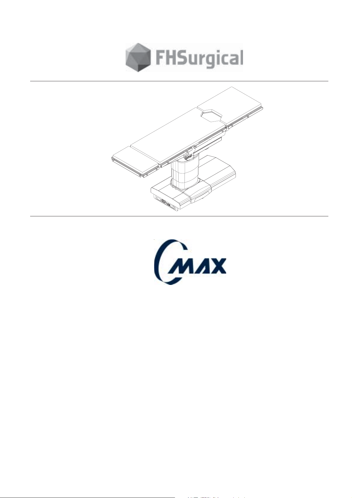
Operating table
C-MAX 38
Operator Manual
C-MAX/NU/11/02 Edition 01F Ref. 022710201
Page 2

Operating table
TABLE OF CONTENTS
1 - Quality Standard ............................................................................................................. 4
2 - Guarantee ...................................................................................................................... 5
3 - Safety instructions .......................................................................................................... 6
3.1 Summary of warnings .....................................................................................................6
3.2 Pinch points .................................................................................................................. 8
3.3 Symbols........................................................................................................................ 11
4 - General description ........................................................................................................... 11
4.1.1 Classification................................................................................................................ 11
4.1.2 Description .................................................................................................................. 13
4.2 Specifications ................................................................................................................ 15
5 - Installation instructions .................................................................................................... 17
5.1 Installing headrest .......................................................................................................... 17
5.2 Headrest manual adjustment ............................................................................................ 17
5.3 Removing and installing leg section................................................................................... 19
5.4 Installing and removing battery fuse.................................................................................. 19
5.5 Connecting and disconnecting mains power cord ................................................................ 21
5.6 Electric power mode ....................................................................................................... 21
5.7 Battery power mode ....................................................................................................... 21
5.8 Connecting and disconnecting hand control ....................................................................... 23
5.9 Connecting and disconnecting optional foot control............................................................. 25
5.10 Connecting to SUB-D socket for E-Serve.......................................................................... 25
6 - Operating instructions......................................................................................................26
6.1 Hand control operations .................................................................................................. 28
6.2 ALS description.............................................................................................................. 32
6.3 Optional foot control operations .......................................................................................34
6.4 Tabletop pads ................................................................................................................ 34
6.5 Optional X ray top ..........................................................................................................35
7 - Patient positioning........................................................................................................... 37
7.1 Surgical procedure : Eye, E.N.T., facial plastic, open heart, abdominal vascular....................... 37
7.2 Surgical procedure : Ophtalmology ................................................................................... 38
7.3 Surgical procedure : Neck surgery .................................................................................... 38
7.4 Surgical procedure : Cranial surgery .................................................................................. 39
a) Prone or supine position .................................................................................................... 39
b) Lateral position ................................................................................................................ 40
7.5 Surgical procedure : Cranial surgery .................................................................................. 40
- Sitting position .................................................................................................................. 41
7.6 Surgical procedure : Plastic and breast surgery................................................................... 42
7.7 Surgical procedure : spinal surgery ................................................................................... 43
a) Prone position .................................................................................................................. 43
b) Knee chest position ..........................................................................................................43
7.8 Surgical procedure : Kidney and thoracic surgery ................................................................ 44
7.9 Surgcial procedure : Urology, Proctology, and Gynecology ................................................... 45
7.10 Surgical procedure : Shoulder Arthroscopy....................................................................... 46
7.11 Surgical procedure : Vascular and Angioplasty.................................................................. 47
A
2
Réf. 022710201
Operator manual
CMAX NU 01F
Page 3

Operating table
8 - Override system ............................................................................................................... 49
8.1 Operating instruction ........................................................................................................ 49
8.2 Replacing override hand control .......................................................................................... 51
9 - Cleaning and disinfecting .................................................................................................... 52
9.1 General instructions ......................................................................................................... 52
9.2 Cleaning and disinfecting ................................................................................................... 52
9.3 Recommended and unsuitable products................................................................................. 53
10 - Maintenance .................................................................................................................. 54
10.1 Key points to be checked every year.................................................................................. 54
10.2 Maintenance tasks for operator ........................................................................................ 55
10.3 Routine maintenance procedure ........................................................................................ 55
10.4 Environmental protection ................................................................................................. 56
10.5 Operator troubleshooting ................................................................................................. 57
10.6 Service procedure .......................................................................................................... 58
10.7 Recommended spare parts ............................................................................................... 58
10.8 Inspection sheet............................................................................................................. 59
CMAX NU 01F
Operator manual Réf. 022710201
3
Page 4
Operating table
Dear customer,
Thank you for choosing the C-MAX operating table, newly proposed by FHSurgical to fully meet your needs.
Please read the instructions carefully to ensure optimum efficiency and safety when using the C-MAX operating
table.
Philippe DAURY, President.
FHSurgical
645, rue des Châtaigniers, BAT 405 - B2,
F 45770 SARAN
QUALITY REQUIREMENTS
Company certifiation and applicable standards
The FHSurgical quality system is certified :
ISO 9001 (2000)
ISO 13488 (2001)
Certificate N° 1605/9001/13488/1
By the G-MED (Medical Device Assessment Body) for the manufacturing, sales, installation and after sales
service for operating tables, table tops, trolleys for transfert system, and for their extensions and accessories.
Note : the ISO 13488 is the international standart dedicated to the medical devices manufacturers.
This table is designed in compliance with international standards IEC 601-1 (EN 60-601-1) electromedical
devices, Part 1: general safety rules and IEC 601-2-46 “electromedical devices, Part 2 : specific safety rules
applicable to operating tables”, and IEC 601-1-2 (EN 60-601-1-2) concerning electromagnetic interference.
CE and UL Marking
The CE marking applied to the table (only for CMAX version 220Volts) is covered by a statement issued by
FHSurgical , and a registration with the l’AFSSAPS (French Agency governing the Sanitary Safety of Health
Products).
The UL2601 certification applied to the table (only for CMAX version 110Volts) has been delivered by
Underwriters Laboratory, to FHSurgical. FILE : N° E237575
4
Réf. 022710201
CMAX NU 01F
Operator manual
Page 5

Operating table
GUARANTEE
FHSurgical warrants the equipment against all defects of materials or manufacture for 12 months after delivery.
The warranty covers only equipment supplied by FHSurgical.
It is limited to replacement of parts acknow-ledged to be defective. The labour, travel, living and insurance expenses
of the crew replacing parts acknowledged to be defective are incumbent on the customer.
Title to replaced parts reverts to FHSurgical and they must be returned to it within one month of replacement;
otherwise FHSurgical reserves the right to bill the value of the replaced part.
Warranty repairs and deplacements do not extend the initial warranty period.
This guarantee does not cover the normal wear and tear of parts, nor does it apply to consumables (in particular
bulbs, fuses, neon tubes, UV tubes, semi-conductors, valves and diodes, rubber seals, mattress, cushions, etc.).
In order to benefit from the terms of this gua-rantee, the Purchaser must inform us of any defect by letter or by
telex followed by letter of confirmation within three days of discovering the defect.
The Buyer must submit to FHSurgical all evidence that the defect is incumbent on FHSurgical and afford FHSurgical
every facility to investigate the same.
The customer may buy spare parts simulta-neously with the equipment.
FHSurgical may use the Buyer's spare parts subject to replacement thereof.
On request, FHSurgical will supply the principal electrical diagrams and lists of parts to duly accredited technicians.
The warranty determines if the supplies are altered or repaired by the Buyer or other par-ties without FHSurgical's
prior written consent.
No damages are recoverable under this warranty, which is personal to the Buyer and determines forthwith if it
disposes of the equipment.
The warranty does not cover:
• incidents caused by fortuitous events or force majeure as described in article X of the general conditions of sales,
• repair or replacement required by normal wear of the equipment,
• damage or accidents due to the customer's act such as negligence, lack of supervision, faulty connection and use/
procedures, disre-gard of the operating or maintenance instructions or improper use due inter alia to overload of any
kind.
CMAX NU 01F
Operator manual Réf. 022710201
5
Page 6
Operating table
3 - Safety instructions :
3.1 Summary of warnings :
During table top operation, several possible pinch points are generated and could result in medical staff or patient
!!
!
!!
injuries. Cutting or crushing injury may occur if any part of a patient or staff member is caught in a pinch point.
People involved must be aware of these risks and review drawings of FIG 3.1, 3.2. (page 8)
If an antistatic path is necessary, we recommend that you only use recommended antistatic pads, specifically
!!
!
!!
designed for this product and on which the patient must be in direct contact.
The operating table must be set on an antistatic floor or connected to an equalization device (equipotential
connector (page 13).
In case of use of other equipments near the table, verify that these equimpents respect the Electromagnetic
!!
!
!!
compatibility medical standards (page 13).
When using high frequency surgical equipment such as defibrillators or defibrillator-monitors, carefully follow the
!!
!
!!
manufacturer’s instructions (page 13).
The table is earthed when table is connected to mains by power cord with earth (page 13).
!!
!
!!
Where the integrity of the external Protective Earth Conductor arrangement is in doubt, equipment shall be
!!
!
!!
operated from its Internal Electrical Power Source (page 13).
Table must be equipped with 2 flame retardant lead sealed batteries 12V, available through the FHSurgical
!!
!
!!
network (page 13).
Do not remove leg plate while patient is not correctly positioned .
Patient’s torso and buttocks must be firmly held in position by the operating table seat plate and his legs
supported by additional leg supports correctly attached to seat plate side rails (refer to leg support’s instructions for use). (page 19)
When leg section is not correctly secured, corresponding LCD angle value does not appear (FIG.5.3) (page 19).
!!
!
!!
Do not use the table in the presence of flammable anesthetics. (page 21)
Prior to all surgical procedures, ensure that battery charge is sufficient for anticipated duration. (page 21)
!!
!
!!
Ensure socket cap covers the socket properly. (page 25)
!!
!
!!
The plug is equipped with a safety lock feature : do not pull on hand control cord to disconnect it from the table
as this will damage it. (page 25)
Only FHSurgical representatives are authorised to use this socket. Otherwise, FHSurgical cannot be held
!!
!
!!
responsible and guarantee does not apply. (page 25)
If the hand control unit and the foot pedal used at the same time, the hand control unit has priority (page 25).
!!
!
!!
Hand control “OFF” key also switches off the foot control. (page 25)
!!
!
!!
The values in the LCD display are given as guidelines. Their accuracy may vary according to environmental
!!
!
!!
conditions (altitude, hydrometry, temperature etc.).
Take care to check patient positioning visually. (page 27)
Table top movements can not be operated when table is unlocked.
!!
!
!!
Lock table before positioning patient on the table and before pressing any table top movement key. (page 28)
6
Réf. 022710201
CMAX NU 01F
Operator manual
Page 7
Operating table
In case of table displacement, with patient on it, table top must be in a flat position, centered in relation to table
!!
!
!!
column.
Prior to this, the user will have to remove any obstacles that might stand in the way and move table with care (page
28).
Since table is locked, ensure table is stable according floor flatness. Relocate table if required (page 29).
!!
!
!!
The information displayed on LCD are not reversed (page 29).
!!
!
!!
When table is turned off, table memorizes orientation status.
!!
!
!!
Before any new positioning, ensure table is correctly configured in relation to patient orientation function. (page 29)
When REVERSE ORIENTATION is activated, level function does not include back section for compliance with anesthesia
!!
!
!!
procedure. (page 31)
In reverse configuration, flex and reflex function are not available for patient safety reasons. «REV. ORIENT.» appears at
!!
!
!!
the LCD message window. (page 31)
Caution : These ALS suggested alternative table movements do not take into account the type of surgery being conducted
!!
!
!!
or the environment (e.g. : other equipment closeby) and might not be compatible with the surgical procedure in process.
To avoid any risk and before carrying out the suggested alternative, the user should evaluate feasibility. (page 32)
Use exclusively recommended FUSION pads. (page 34)
!!
!
!!
Ensure that it has been correctly secured, by pulling lightly double top up. (page 35)
!!
!
!!
Do not exceed 600 lbs patient weight using standard positions specified. (chap.7 - page 37)
If a heavy patient (500-600 lbs) is placed on the tabletop in full slide towards patient head end, caution should be used to
!!
avoid bumping the table, which can cause the table to tip. If chest compressions or other forces need to be applied on a
!
!!
500-600 lbs patient, the patient should be centered over the column. (page 37)
The positionings described below are given as an example only. They do not replace instructions given by the health care
!!
!
!!
professionals in charge of the patient to prevent any patient injury.
Accessories here-below are not systematically representated. (page 37)
Possible patient or user injury may result from using accessories manufactured and sold by other companies. (page 37).
!!
!
!!
When override hand control is in use, primary hand control automatically shuts off, after 1 second. (page 51)
!!
!
!!
In override mode, no sensor is available (A.L.S. off) : when articulating table top, take care to avoid section collision with
!!
!
table top (e.g. : when sliding), with table base or with the floor. (page 51)
!!
In override mode, lock table before articulating table top. (page 51)
!!
!
!!
There is no reverse orientation key in override mode. Controls are configured in normal orientation.
!!
!
!!
When table is turned to back up mode, table does not memorise orientation status.
Before articulating table top, take into account patient orientation. If patient is in Reversed Orientation, change TREND
selection to REV. TREND., BACK SECTION to LEG SECTION, LEFT TILT to RIGHT TILT, and vice versa. (page 51)
Take care not to jam cable when replacing drawer. (page 51)
!!
!
!!
Before any cleaning operation :
!!
!
!!
Switch off the table
Disconnect the control unit
Fit watertight covers on each connector. (page 52)
Do not immerse hand control unit in liquid. (page 52)
Do not spray solutions in direction of connectors. (page 52)
Do not forget to clean wheels and floor blocks. (page 53)
Do not use any oxidizing products with chloric derivative base such as bleach, or oxygenic derivatives such as peracetic
CMAX NU 01F
acid. (page 53)
Operator manual Réf. 022710201
7
A
Page 8
Operating table
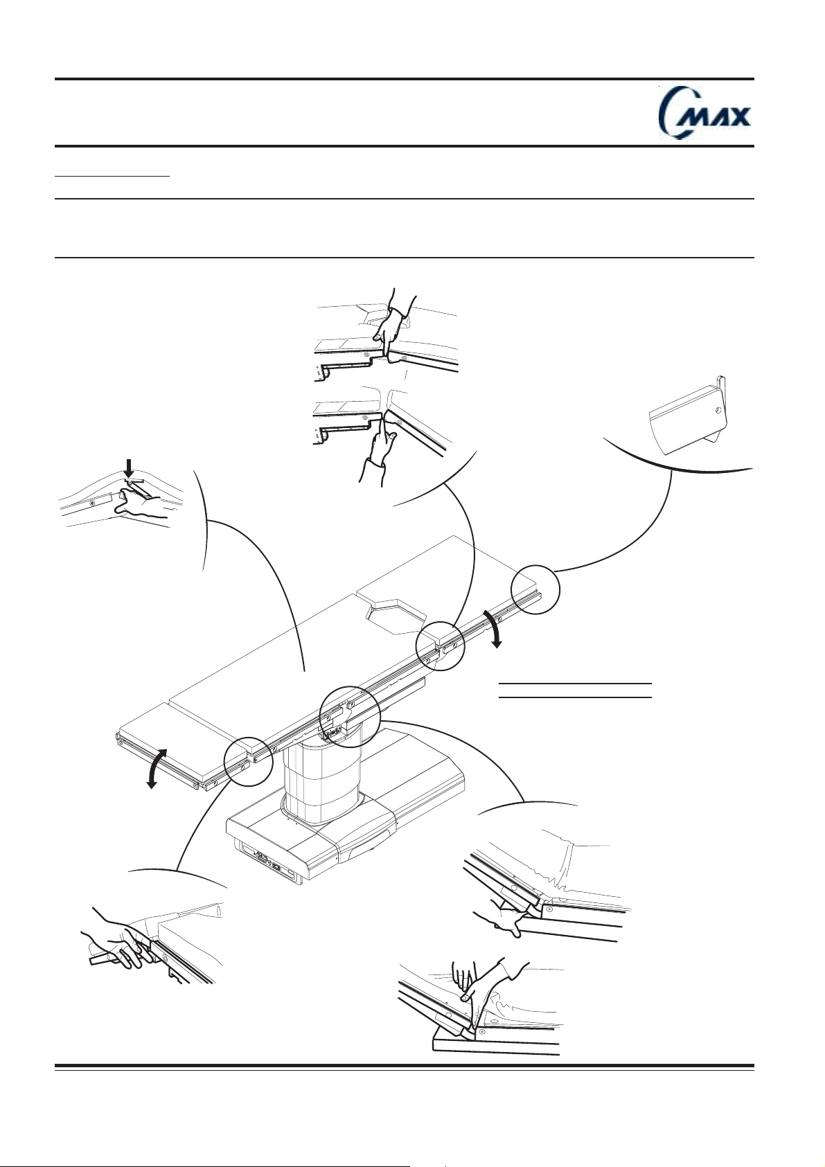
3.2 Pinch points :
During table top operation, several possible pinch points are generated and could result in medical staff or patient
!!
!
!!
injuries.
Cutting or crushing injury may occur if any part of a patient or staff member is caught in a pinch point.
People involved must be aware of these risks and review drawings of FIG 3.1 and 3.2.
FIG. 3.1 PINCH POINTS
r
e
v
o
c
.
s
e
p
s
a
u
c
n
e
i
r
t
u
o
s
n
n
E
n
e
h
w
s
t
e
k
c
o
s
E
V
R
E
S
C-MAX 07
WA
R
N
I
N
G
AV
E
R
T
I
S
S
E
M
E
N
T
C
H
A
R
G
E
I
N
T
E
WA
L
L
I
B
P
R
A
T
O
T
N
E
R
W
Y
I
N
E
AV
G
R
E
R
T
I
S
W
S
0
1
E
0
9
M
-
F
2
D
0
E
0
L
0
N
K
-
M
S
T
W
C
.
M
A
X
CMAX NU 01F
8
Réf. 022710201
Operator manual
Page 9
Operating table
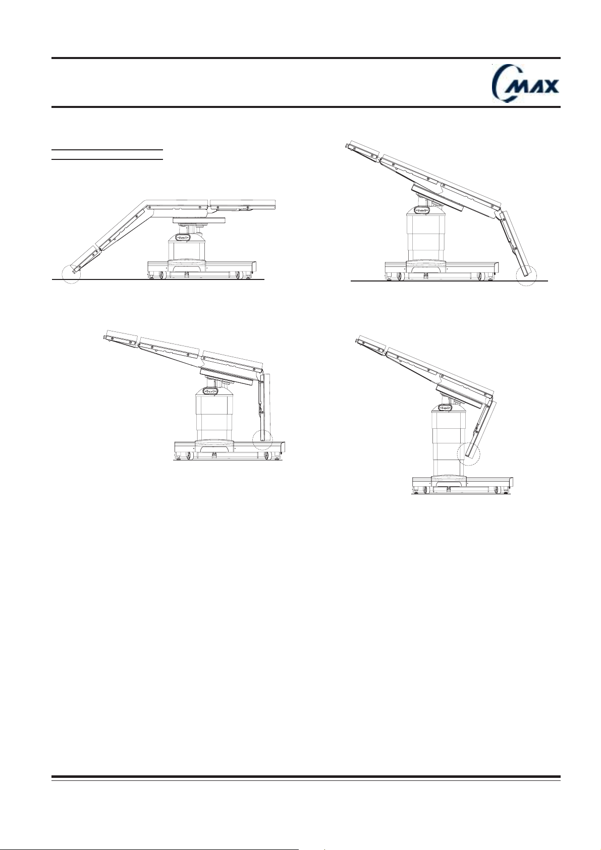
FIG. 3.2 PINCH POINTS
C-MAX 29
C-MAX 31
C-MAX 30
C-MAX 36
CMAX NU 01F
Operator manual Réf. 022710201
9
Page 10
Operating table
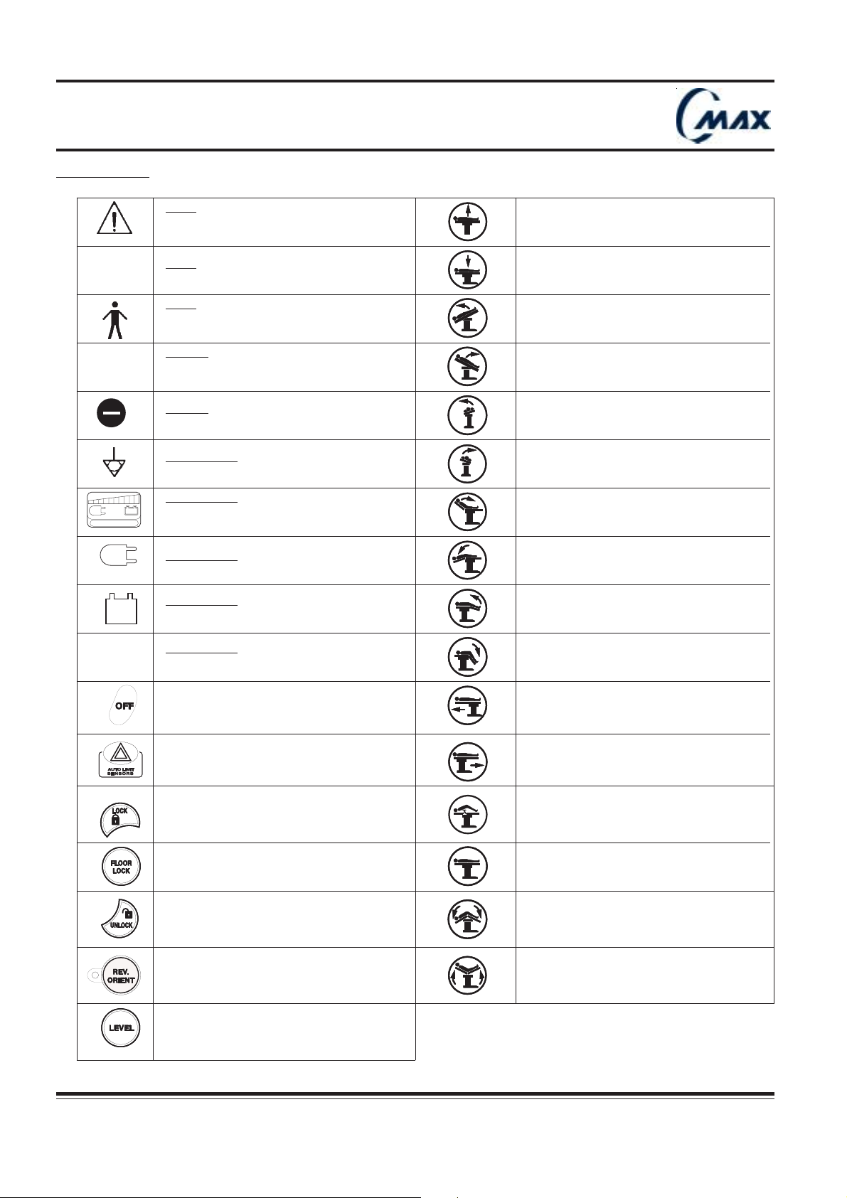
3.3 Symbols :
Label :
Warning : consult the accompanying
documents
Height up (page 29)
IPX 4
!!
!
!!
CHARGE BATTERY
INTELLI POWER
0 / I
Label :
Protected against water splashes
Label :
Type B appliance : Protection against
electric shocks
Manual :
Remarks are aimed at attracting the
reader’s attention to particular points
Manual :
Not allowed
Power panel :
Equipotentiality plug
Power panel :
Battery charge/discharge status
(page 21)
Power panel :
Table works on batteries (page 21)
Power panel :
Table works on mains (page 21)
Power panel :
Mains off / Mains on (page 20)
Height down (page 29)
Trendelenburg (page 29)
Reverse trendelenburg (page 29)
Tilt left (page 30)
Tilt right (page 30)
Back up (page 30)
Back down (page 30)
Leg up (page 30)
Leg down (page 30)
10
Stop function (page 28)
Auto limit sensors (page 32)
Lock table on floor (page 28)
Floor lock (page 28)
Unlock table (page 28)
Patient orientation (page 29)
Level (page 31)
Réf. 022710201
Slide head (page 30)
Slide foot (page 30)
Kidney up (page 30)
Kidney down (page 30)
Flex (page 31)
Reflex (page 31)
CMAX NU 01F
Operator manual
Page 11
Operating table
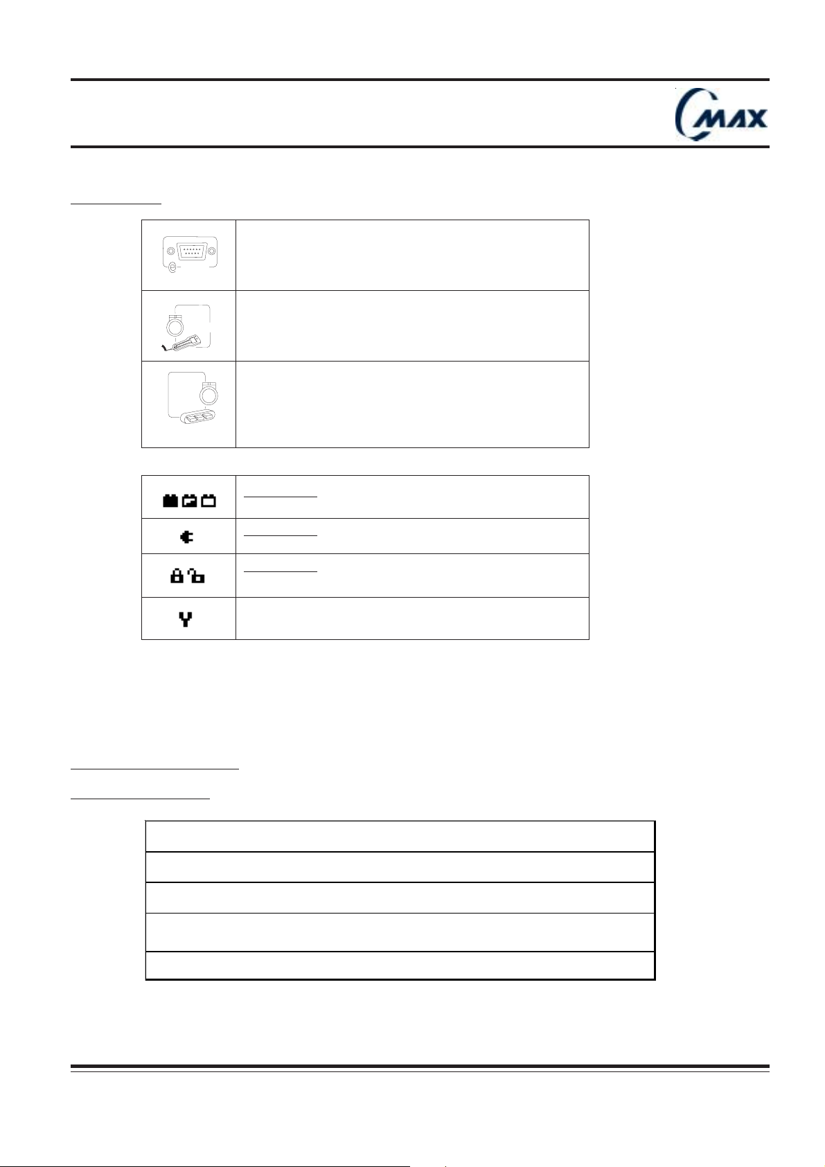
3.3 Symbols :
SERVE
SUB-D socket for E-SERVE: for
connecting exclusively FHSurgical
computer or modem (diagnostics)
(page 25)
Socket 1 : for plugging in hand control
(page 25)
Socket 2 : for plugging in optional foot
control (page 25)
Hand control : Table works on batteries.
Battery status full charge / half charge / discharge (page 21)
4. GENERAL DESCRIPTION :
4.1.1 CLASSIFICATION
CLASS 1 equipment
Type B equipm ent
Splash-proof equipment (IPX4)
Equipm ent not s ui t able for use in t he pres enc e of a flammable anaes t het i c m ixt ure
with ai r or wit h oxygen or nitrous ox i de
Hand control :
Status : table works on mains (page 21)
Hand control :
Status : table lock / table unlock (page 21)
Maintenance key (page 57)
Intermit t ent operat ion 3m n/ h
CMAX NU 01F
Operator manual Réf. 022710201
11
A
Page 12
Operating table
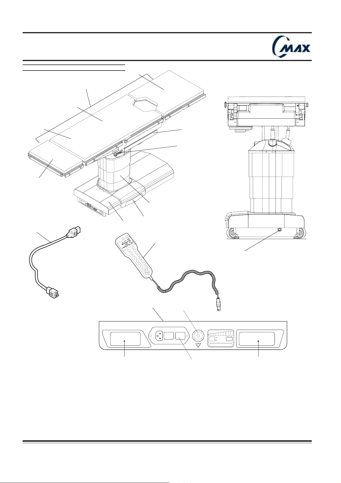
FIG. 4.1.2 - DESCRIPTION
6
5
4
WA
R
N
I
N
AV
E
R
T
I
10
8
3
7
r
e
v
o
c
.
s
e
p
s
a
u
c
n
e
i
r
t
u
o
s
n
n
E
n
e
h
w
s
t
e
k
c
o
s
E
V
R
E
S
G
S
S
E
M
E
N
T
C
H
A
R
G
E
I
N
T
E
WA
L
L
I
B
P
R
A
TT
O
N
E
R
W
Y
I
N
E
AV
G
R
E
R
T
I
S
W
S
0
1
E
0
9
M
-
F
2
D
0
E
0
L
0
K
N
-
M
S
T
W
C
.
M
A
X
1
"
¡
3
4
0
0
T
-
L
I
T
¡
0
T
0
!
¡
0
D
2
A
E
H
"
0
E
0
D
I
L
S
¡
0
0
D
N
E
R
T
2
14
13
12
C-MAX 38
C-MAX 09
11
9
16
15
18
CHARGE BATTERY
INTELLI POWER
1 - Mobile base 9 - Power panel 17 - Identification label
2 - Column 10 - Power Cord 18 - Primary fuses
3 - Table top 11 - Battery fuse holder
4 - Headrest 12 - Connection panel
5 - Back section 13 - Hand control
6 - Kidney elevator 14 - Override
7 - Sliding seat section 15 - Equipotentiality plug
8 - Leg section 16 - Electrical characteristics label
12
Réf. 022710201
C-MAX 26
17
CMAX NU 01F
Operator manual
Page 13
Operating table
4.1.2 - Description :
C-MAX is a mobile, motorized electro-hydraulic operating table.
Equipped with a large sliding table top (ZIP SLIDE pending patent), C-MAX provides unrestricted radiological
access without patient reversing.
C-MAX is suitable for most surgical procedures and is designed to support patient weighing up to 600 lb (270 kg)
using standard positions specified chapter 7.
The unique concept of its power supply (INTELLI POWER pending patent) allows the table to be either battery powered
or electric powered.
Movements are executed through wired hand control (13) or optional foot control. Also, C-MAX is voice and touch
screen control compatible.
C-MAX operating table is comprised of a mobile base (1), a column (2), and a multi-section tabletop (3) which is
divided into 5 sections :
- a headrest (removable) (4)
- a back section (5)
- a kidney elevator (6)
- a sliding seat section (7)
- a leg section (removable) (8)
Back, kidney, seat and leg sections movements are motorized.
Headrest adjustment is manual.
C-MAX smart electronic design allows diagnostic and servicing to be performed from a distance by FHSurgical‘s
specialists (E-SERVE compatible).
Built-in sensors provide safety information to the users. These sensors prevent sectional conflict and detect accidental
table collisions with external obstructions (AUTO LIMIT SENSORS pending patent).
Electrical power supply :
Input for CMAX 110 Volts : 100/120 Volts (shunt inside) 50-60 Hz 1 Phase 380 VA max.
A 3.7-meter long power cord hospital grade (10) is provided to connect the table to the mains.
Primary protection by 2 fuses : T 6,3 AH (18)
Input for CMAX 220Volts : 220/230 Volts (shunt inside) 50-60 Hz 1 Phase 380 VA max.
A 5-meter long power cord hospital grade (10) is provided to connect the table to the mains.
Primary protection by 2 fuses : T 4 AH (18)
Mode of operation : 3 min / hour intermittent use
Insulation :C-MAX is equipped with a equipotentiality plug (15) (male connector, DIN42801) at the power panel (9)
to prevent electric shock. Female connector not provided by FHSurgical.
5.5 - Connecting and disconnecting mains power cord :
If an antistatic path is necessary, we recommend that you only use recommended antistatic pads, specifically
designed for this product and on which the patient must be in direct contact.
!!
!
!!
The operating table must be set on an antistatic floor or connected to an equalization device (equipotential
connector).
In case of use of other equipments near the table, verify that these equimpents respect the Electromagnetic
!!
!
!!
compatibility medical standards
When using high frequency surgical equipment such as defibrillators or defibrillator-monitors, carefully follow the
!!
!
!!
manufacturer’s instructions.
The table is earthed when table is connected to mains by power cord with earth.
!!
!
!!
Where the integrity of the external Protective Earth Conductor arrangement is in doubt, equipment shall be
!!
!
!!
operated from its Internal Electrical Power Source.
Table must be equipped with 2 flame retardant lead sealed batteries 12V, available through the FHSurgical network.
!!
!
!!
CMAX NU 01F
Operator manual Réf. 022710201
13
A
Page 14
Operating table
Ensurecapscover
socketswhennotinuse.
SERVE
C-MAX 13
90°
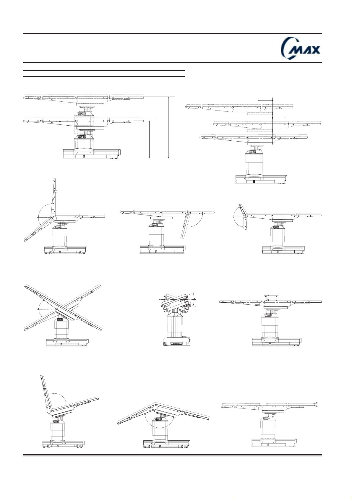
FIG. 4.2 - MOUVEMENT RANGE
9"
227mm
40°
90°
Ensurecapscover
socketswhennotinuse.
SERVE
Ensurecapscover
socketswhennotinuse.
SERVE
C-MAX 21
26"
675mm
45"
1136mm
Ensurecapscover
socketswhennotinuse.
SERVE
9"
227mm
C-MAX 19
60°
Ensurecapscover
socketswhennotinuse.
Ensurecapscover
socketswhennotinuse.
SERVE
C-MAX 14
SERVE
105°
C-MAX 16
90°
Ensurecapscover
socketswhennotinuse.
SERVE
C-MAX 12
30°
30°
20°
20°
Ensurecapscover
socketswhennotinuse.
SERVE
C-MAX 15
Ensurecapscover
socketswhennotinuse.
SERVE
W0109-2000-SW
FDLKM-C.MAX
WARNING
WARNING
AVERTISSEMENT
AVERTISSEMENT
CHARGE BATTERY
INTELLIPOWER
C-MAX 18
4" 110mm
Ensurecapscover
socketswhennotinuse.
SERVE
C-MAX 23
2’’
140°
C-MAX 17
CMAX NU 01F
14
Réf. 022710201
Operator manual
Page 15
Operating table
4.2 - Specifications :
- Up / Down : 45’’ - 1136 mm / 26’’ - 675 mm
- Lateral tilt left / right : 20°/20°
- Trendelenburg / reverse Trendelenburg : 30°/30°
- Back section Up / Down : 90°/40°
- Leg section Up / Down : 0°/105°
- Kidney elevator : 4’’ - 110 mm
- Slide Head / Foot : 9’’ - 227 mm / 9’’ - 227 mm
- Flex / reflex : 140° / 90°
- Headrest adjustment is manual : Up/ Down : 60° / 90°
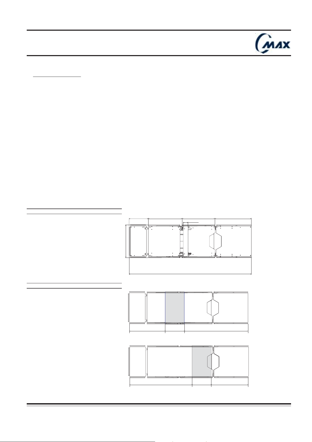
- Tabletop dimensions : Length : 81’’ - 2055 mm
Width (access rails) : 22’’ - 550 mm
- Table weight : Approximatively 560 lb (250 kg)
- Patient weight capacity : 600 lb (270 kg), for standard positions defined on chapter 7.
FIG. 4.3 - TABLE TOP DIMENSIONS
FIG. 4.4 - X-RAY ACCESS
(325mm)
22” (550mm)
13”
25”
(635mm)
22”
(570mm)
Column
(330mm)
81” (2055mm)
13”
22”
(550mm)
3” (80mm)
43”
(1090mm)
24”
(610mm)
C-MAX 32a
43”
(1088mm)
CMAX NU 01F
Operator manual Réf. 022710201
Column
13”
(330mm)
25”
(637mm)
C-MAX 24a
15
Page 16
Operating table
FIG. 5.1 - INSTALLING HEADREST
C-MAX 01b
FIG. 5.2 - HEADREST ADJUSTMENT
60°
90°
C-MAX 02a
Handle
Ensurecapscover
socketswhennotinuse.
SERVE
C-MAX 12
16
Réf. 022710201
CMAX NU 01F
Operator manual
Page 17

Operating table
5 - Installation instructions :
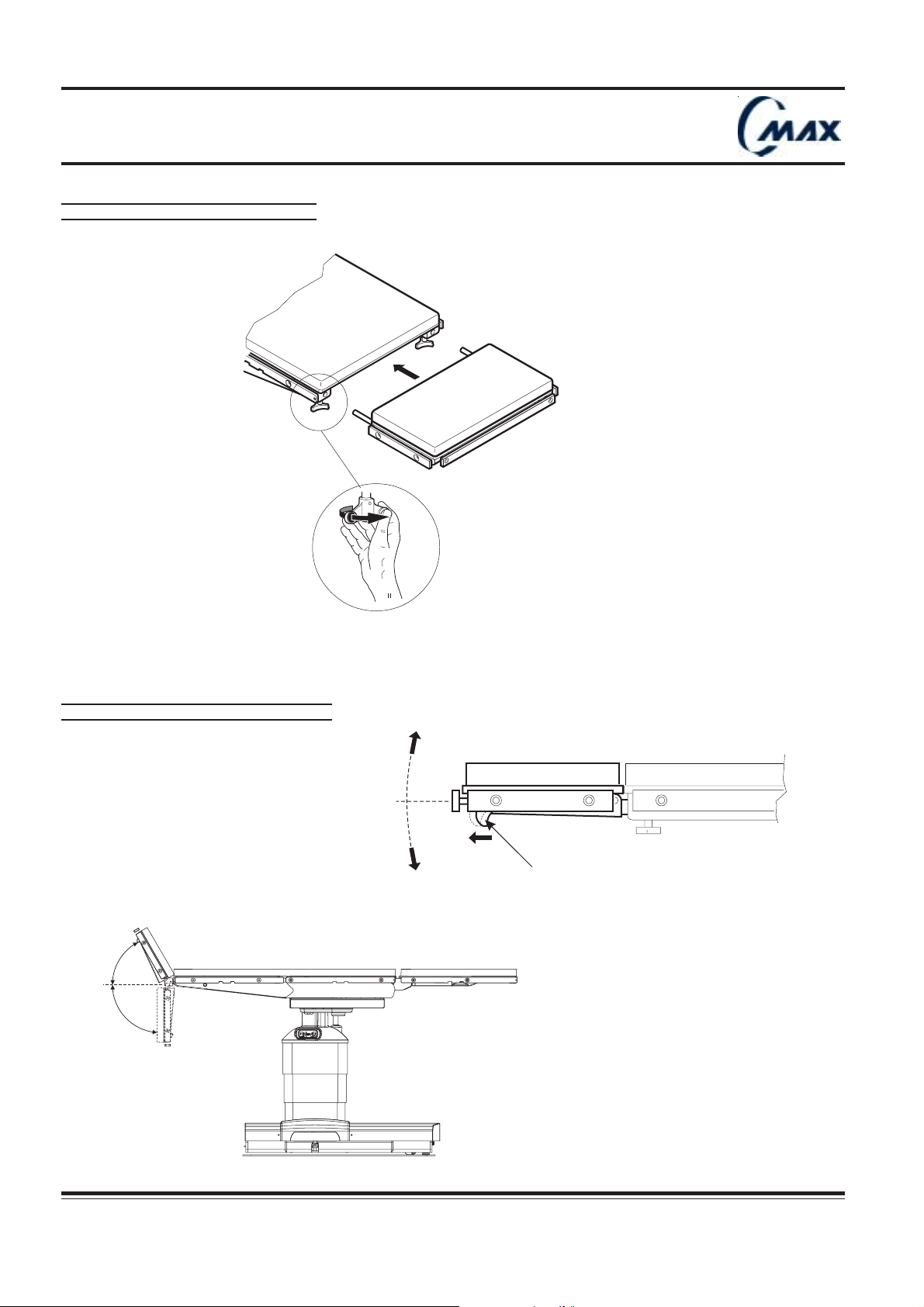
5.1 - Installing headrest (FIG. 5.1) :
Attach the headrest at the end of the back frame as follows :
1. Fully loosen the two locking device thumbscrews located at the end of the back frame.
2. Insert both rods of the headrest attachment into the two back frame bores until fully engaged. The head rest
must fit in easily.
3. Fully tighten the two thumbscrews to secure the headrest in place.
By pulling the headrest on both sides, check that it has been correctly secured.
5.2 - Headrest manual adjustment (FIG. 5.2) :
The headrest can be continuously tilted downwards and upwards from horizontal level (max 90° downwards and
max. 60° upwards) as follows :
1. Pull handle located under right side of headrest and tilt the headrest to desired angle, at the same time, holding
full weight of patient’s head on headrest.
2. Once the tilt has been obtained, release the handle.
CMAX NU 01F
Operator manual Réf. 022710201
17
Page 18
Operating table
C-MAX 08bb
03"
00"
20° T
00°
TREND TILT
00°
LEG OUT
FIG. 5.3 - REMOVING LEG SECTION
Ensurecapscover
socketswhennotinuse.
SERVE
C-MAX03a
Handle
Hand control LCD display
No
angle
value
FIG. 5.5 - INSTALLING BATTERY FUSE
FIG. 5.4- INSTALLING LEG SECTION
Ensurecapscover
socketswhennotinuse.
SERVE
C-MAX 09
C-MAX03b
«
CLICK
»
18
Réf. 022710201
CMAX NU 01F
Operator manual
Page 19
Operating table
5.3 - Removing and installing leg section :
The C-MAX leg section is designed to be removable (Hi-lock,pending patent) in order to provide free access to the
surgeon while using additional leg supports (refer to patient positionning, chap. 7)
Do not remove leg section while patient not correctly positioned.
Patient’s torso and buttocks must be firmly held in position by the operating table seat plate and his legs
supported by additional leg supports correctly attached to seat section side rails (refer to leg support’s
instructions for use).
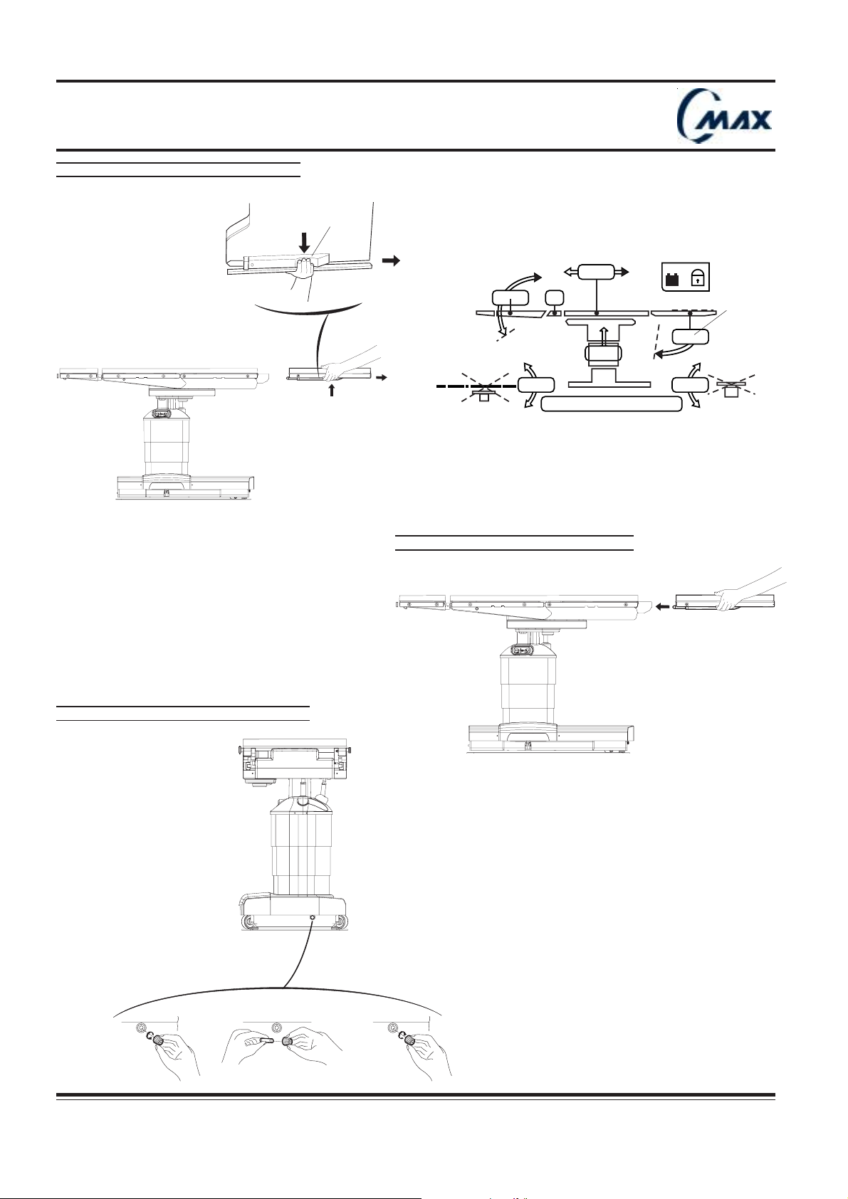
Remove the leg section as follows (FIG. 5.3) :
1. Position leg section horizontally using hand control.
2. While holding the leg frame, press both handles and simultaneously pull backwards.
Stow leg plate close by with care.
N.B. : Seat articulation interfaces can be folded down to provide better access for surgeon.
When leg section removed, corresponding LCD angle value disappears (refer to hand control operations, chap.6.1)
Installing leg section (FIG. 5.4) :
1. Position seat articulation interfaces horizontally (leg up max.) using hand control leg section upwards key.
2. Insert both rods for the leg frame attachment into the seat bores until fully engaged. Listen to the «Click» which
indicates that the leg section is correctly engaged. The leg frame must fit in easily.
It is not necessary to press handles.
By pulling the leg section on both sides, ensure that it has been correctly secured.
When leg section is not correctly secured, corresponding LCD angle value does not appear (FIG.5.3) and
!!
!
!!
«LEG OUT» appears at the hand control LCD message window when pressing «LEG UP» or «LEG DOWN»
key.
5.4 - Installing and removing battery fuse :
For safety and transport purposes, the protection fuse is packaged separately in a plastic bag attached to the table.
Installing battery fuse (FIG. 5.5) :
- Remove the fuse from its bag.
1. Unscrew the black fuse holder cap located at the front of the table base
2. Insert the fuse in the black fuse cap.
3. Insert the fuse and the fuse holder assembly in its housing.
Push in and turn the fuse holder a quarter turn clockwise to screw it into place.
- Pull on the fuse cap to ensure it is properly secured to the table.
If table remains in extended storage (more than 6 months), remove fuse to limit battery discharging and to maintain
proper charge.
To prevent table batteries from any damage, keep premises temperature between 5°F (-15°C) and 122°F (50°C).
Removing the battery fuse :
The fuse is removed by unscrewing the fuse cap anti-clockwise.
CMAX NU 01F
Operator manual Réf. 022710201
19
Page 20
Operating table
C-MAX 08aa
03"
00"
20° T
00°
TREND TILT
00°
SLIDE HEAD !
04°
0
3
"
0
0
"
2
0
¡
T
0
0
¡
T
R
E
N
D
T
I
L
T
0
0
¡
S
L
I
D
E
H
E
A
D
!
-
0
4
¡
698 2
3
41 5
7
AUTO
LIMIT
SENSORS
FIG. 5.6 - CONNECTING POWER CORD
Ensurecapscover
socketswhennotinuse.
SERVE
FIG. 5.7.1 - HAND CONTROL LCD DISPLAY
C-MAX 04
0 I
ON
C
H
A
R
G
E
I
N
T
E
L
L
FIG. 5.7.2 - LED DISPLAY
Label 1 Label 2
ORANGE
0 I
OFF
I
B
P
A
T
O
T
E
R
W
Y
E
R
C-MAX26c
CHARGE BATTERY
INTELLI POWER
GREEN
20
CHARGE BATTERY
Réf. 022710201
CMAX NU 01F
Operator manual
Page 21
Operating table
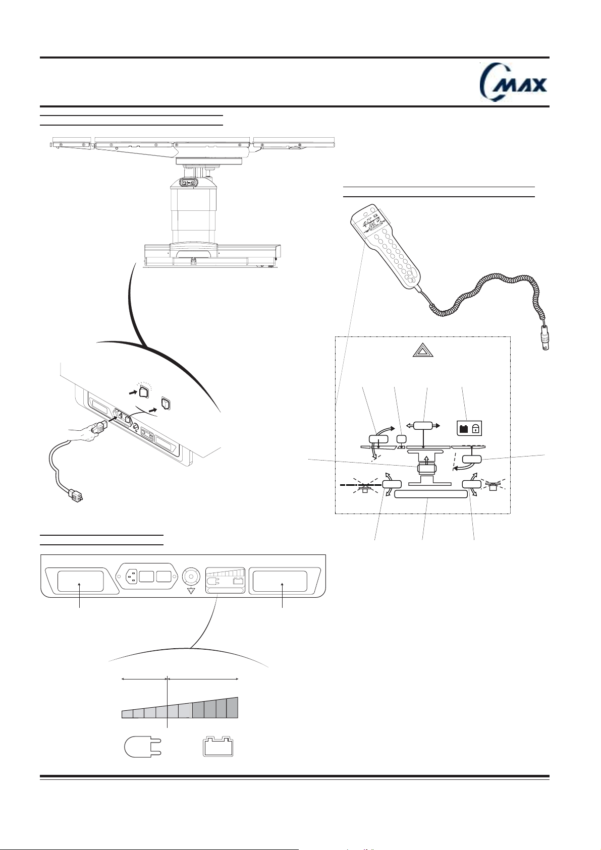
To connect the table to the mains, proceed as follows (FIG. 5.6) :
1. Plug the 3.7-meter (or 5-meter for european version) long power cord to the male connector of the table power
panel.
2. Connect the cord to the mains.
3. Switch mains switch on (I).
The mains switch green light and the plug symbol light up.
Mains switch green light indicates mains power available. Plug symbol indicates that batteries are charging.
Do not use the table in the presence of flammable anesthetics.
To disconnect the power cord, proceed in reverse order.
INTELLI POWER (patent pending)
The unique concept of C-MAX power supply allows the table to be either battery powered or electric powered.
5.6 ELECTRIC POWER MODE
The table is permanently connected to the mains.
The mains switch green light and plug symbol + are on. Battery charge status is continuously
provided by the LED display of power panel.
5.7 BATTERY POWER MODE
If table is used in a battery power mode and hand control is on, the battery symbol + are on.
The mains power cord is disconnected.
Battery discharge status is continuously provided by the LED display of power panel and by the hand control indicator
(refer to hand control operations, chap 6.1).
a) Battery Discharge Status :
The LED display (FIG. 5.7) and hand control LCD display (FIG. 5.7.1) indicates gradually battery discharge status :
- LED display at the power panel indicates battery discharging during movements and battery status when no
movement is done.
- Battery status indicator, at the hand control, indicates only battery status.
- When orange and green diodes are on, they indicate that the battery power supply is normal.
Battery status indicator : appears at the LCD message window.
- When 2 green diodes are off, they indicate that batteries are half discharged. This level of power allows the table
to operate normally without damaging the batteries.
Batteries must be recharged before last green diode light goes out.
Battery status indicator : appears at the LCD message window
- All green diodes are out : batteries are discharged. Batteries must be recharged without further delay.
Battery status indicator : appears at the LCD message window
All green and orange diodes are out : batteries are over discharged and table can only work on mains.
Prior to all surgical procedures, for anticipated duration, ensure that battery charge is sufficient to
!!
!
!!
perform the surgical procedures.
CMAX NU 01F
Operator manual Réf. 022710201
21
Page 22
Operating table
FIG. 5.8 - CONNECTING AND DISCONNECTING HAND CONTROL
Ensurecapscover
socketswhennotinuse.
SERVE
r
e
v
o
c
.
s
e
p
s
a
u
c
n
e
i
r
t
u
o
s
n
n
E
n
e
h
w
s
t
e
k
c
o
s
SERVE
C-MAX 04
FIG. 5.8.1 - CONNECTING
FIG. 5.9 - CONNECTION PANEL
FIG. 5.8.2 - DISCONNECTING
Ensure caps cover
sockets when not in use.
T
R
E
N
D
0
0
¡
S
L
I
D
0
E
0
"
H
E
A
2
D
0
¡
!
0
T
0
¡
T
IL
-
T
0
0
4
3
¡
"
22
SERVE
Socket 2 Socket 1Sub. D socket
Réf. 022710201
C-MAX 25
CMAX NU 01F
Operator manual
Page 23
Operating table
b) Recharging batteries :
If table is used in the battery power mode (power cord disconnected), recharge batteries regularly by connecting table
to the mains and pushing mains switch on. Maximum charging time = 12 hours.
When batteries are fully charged, 100 to 150 procedures (approx. 3 weeks ) are possible without recharging.
Batteries are automatically recharging when table is connected to the mains and mains switch is on.
The LED display gradually indicates charge status of batteries..
Batteries are fully charged when all diodes orange and green are on. Chosing mode always starts at minimum (2 orange
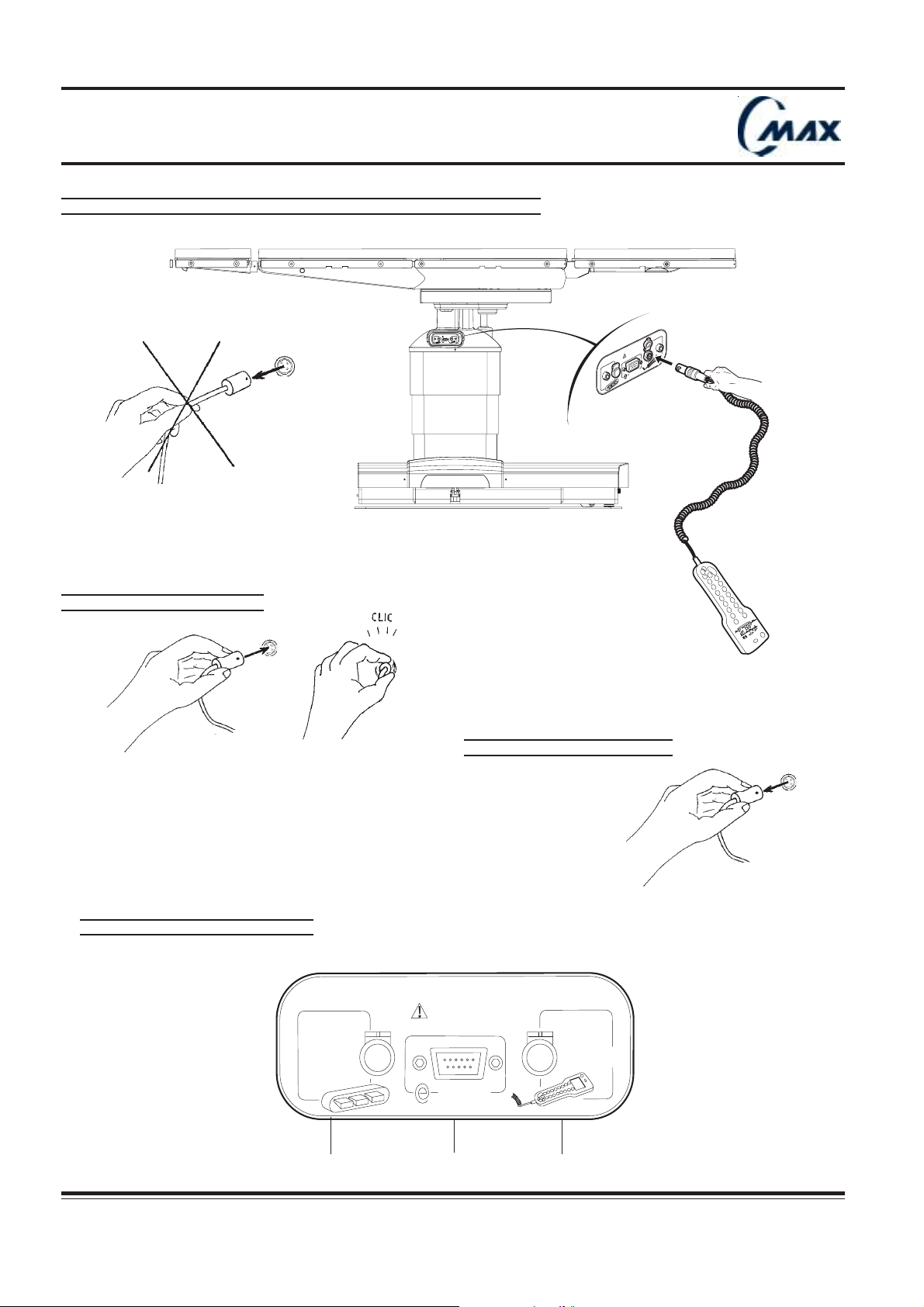
diodes on only), and increase quickly if batteries are charged.
Regular battery recharging will prolong battery life
5.8 - Connecting and disconnecting hand control :
The control unit is packed separately.
Connecting the hand control (FIG. 5.8) :
Remove the hand control from its package.
The hand control has to be connected to the connection panel socket 1 (FIG. 5.9) as follows :
1. Light up the table connector’s protective cover.
2. Align the red mark on the hand control plug with the mark on the table socket.
3. Push the hand control plug fully into the socket 1.
Listen to the “click” which indicates that the hand control is properly connected.
Press any key (except “OFF”) of the hand control to start up the table. This handset will allow the table to be moved
or secured to the floor, and controls all the movements (refer to hand control operations, chap 6.1).
Disconnecting the hand control :
1. Switch it off.
2. Grasp the body of the hand control plug and pull it out from the socket.
The plug is equipped with a safety lock feature : do not pull on hand control cord to disconnect it from the table
as this will damage it.
Ensure socket cap covers the socket properly.
!!
!
!!
CMAX NU 01F
Operator manual Réf. 022710201
23
Page 24
Operating table
FIG. 5.10 - CONNECTING AND DISCONNECTING OPTIONAL FOOT CONTROL
r
e
v
o
c
.
s
e
p
s
a
u
c
n
e
i
r
t
u
o
s
n
n
E
n
e
h
w
s
t
e
k
c
o
s
E
V
R
E
S
Ensurecapscover
socketswhennotinuse.
SERVE
C-MAX 04
FIG. 5.8.1 - CONNECTING
FIG. 5.9 - CONNECTION PANEL
Ensure caps cover
sockets when not in use.
SERVE
FIG. 5.8.2 - DISCONNECTING
C-MAX 25
24
Socket 2 Socket 1Sub. D socket
Réf. 022710201
CMAX NU 01F
Operator manual
Page 25

Operating table
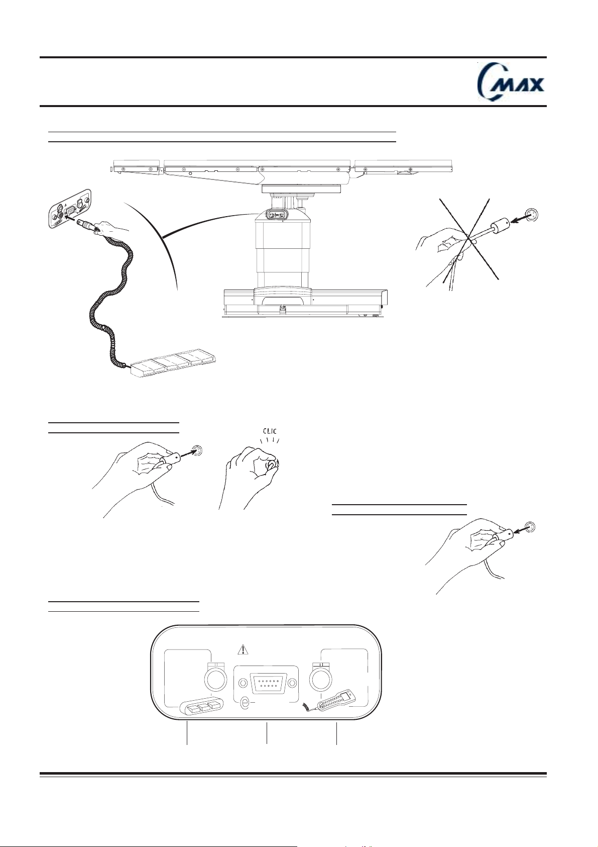
5.9 - Connecting and disconnecting optional foot control :
The foot control allows to adjust HEIGHT, TREND and TILT movements.
Connecting the optional foot control (FIG. 5.10) :
- Remove the foot control from its package.
The foot control has to be connected to the connection panel socket 2 (FIG. 5.9) as follows :
1. Light up the table connector’s protective cover.
2. Align the red mark on the foot control plug with the mark on the table socket.
3. Push the foot control plug fully into the socket 2.
Listen to the “click” which indicates that the foot control is properly connected.
- Press and release any positioning pedal to switch on foot control (refer to foot control user’s instructions).This will
automatically switch on the table. “PEDAL ON” appears at the hand control LCD message window.
This safety measure limits undesired table movement due to pedal short circuiting.
If the hand control unit and the foot pedal used at the same time, the hand control unit has priority.
!!
!
!!
Hand control “OFF” key also switches off the foot control.
!!
!
!!
Disconnecting the foot control :
- Grasp the body of the foot control plug and pull it out from the socket.
Ensure socket cap covers the socket properly.
!!
!
!!
The plug is equipped with a safety lock feature : do not pull on hand control cord to disconnect it from the table
!!
!
!!
as this will damage it.
5.10 - Connecting to SUB-D socket for E-SERVE (FIG. 5.9) :
- C-MAX smart electronic design allows diagnostic and servicing to be performed from a distance by FHSurgical‘s
service specialists (E-SERVE compatible)
Sub-D socket located at the connection panel is for authorized technical service, computer interface only.
- This plug must not be used for other purposes.
Ensure cap always covers the socket properly.
!!
!
!!
Only FHSurgical representatives are authorised to use this socket. Do not connect any equipment without prior
!!
!
!!
FHSurgical agreement. Otherwise, FHSurgical cannot be held responsible and guarantee does not apply.
CMAX NU 01F
Operator manual Réf. 022710201
25
Page 26
Operating table
6 - Operating Instructions :
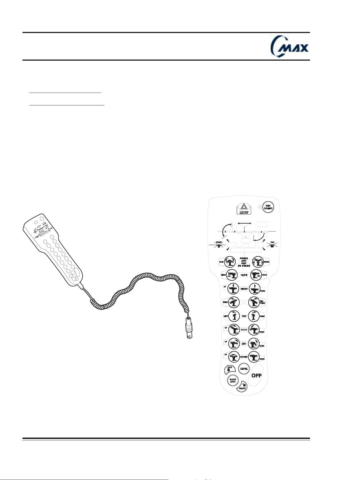
The hand control unit includes :
1. a 3-meter long spiral cable with a plug to be connected to the table (refer to chapter 5.8).
The junction with the box is made by a connector to facilitate cable replacement;
2. an easy-to-hold soft box containing electronics. At the reverse side of the box there is a hook to hang the hand
control from table side rails;
3. a backlighted keyboard with LCD display. This display will provide table status and instructions to the user.
"
¡
3
4
0
0
-
TILT
¡
0
T
0
!
¡
0
D
2
A
E
H
"
0
E
0
D
I
L
S
¡
0
0
D
EN
R
T
26
Réf. 022710201
CMAX NU 01F
Operator manual
Page 27
Operating table
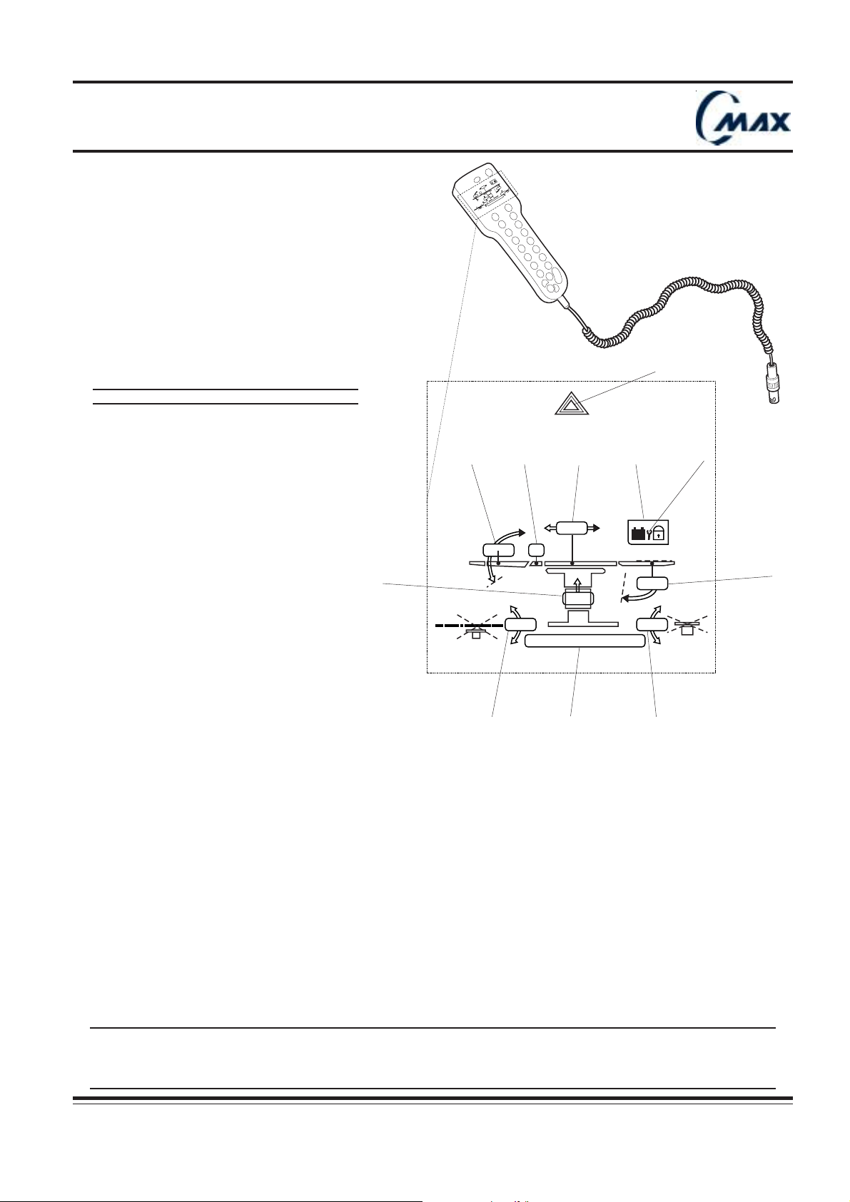
FIG. 6.1 - LCD DISPLAY DESCRIPTION
03"
-04¡
TILT
T
00¡
20¡
00"
SLIDEHEAD !
00¡
TREND
10
LIMIT
AUTO
SENSORS
698 2
03"
20° T
3
TREND TILT
00"
00°
SLIDE HEAD !
1 LCD Message
2 LCD Status Indicators
3 Height stroke level value (from 0 to 18 inches/46cm)
41 5
4 Trendelenburg or Reverse Trendelenburg angle value
Upward pointing arrow : Trend angle value (from 0 to 30°)
Downward pointing arrow : Reverse Trend value (from 0 to 30°)
5 Lateral tilt angle value
Upward pointing arrow : Right tilt angle value (from 0 to 20°)
Downward pointing arrow : Left tilt angle value (from 0 to 20°)
6 Back plate angle value : relative angle value in relation to seat plate level
Upward pointing arrow : back plate angle value up to seat plate level (from 0 to 90°)
Downward pointing arrow : back plate angle value down to seat plate level (from 0 to 45°)
7 Leg plate angle value : relative angle value in relation to seat plate level (from 0 to 105°)
8 Slide value in relation to table top central position
Leftward pointing arrow : head slide value (from 0 to 9 inches/22cm)
Rightward pointing arrow : foot slide value (from 0 to 9 inches/22cm)
9 Kidney status :
“T “ symbol is on : « kidney elevator is up »
No «T» symbol : « kidney elevator » is completely back in position
10 ALS warning
11 Maintenance key
04°
00°
11
7
C-MAX 08aa
The values in the LCD display are given as guidelines. Their accuracy may vary according to environmental
conditions (altitude, hydrometry, temperature, etc.)
!!
!
!!
Should a sensor not work properly, the value indicated will be wrong.
Take care to check patient positionning visually.
CMAX NU 01F
Operator manual Réf. 022710201
27
Page 28
Operating table
6.1 - Hand control operations :
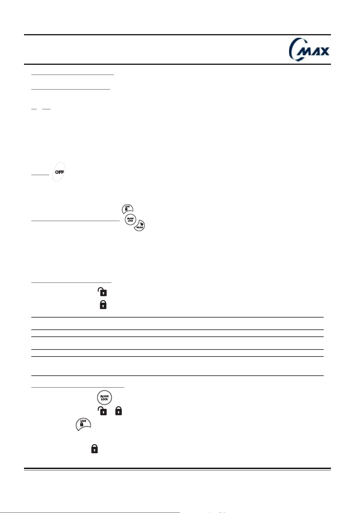
Description of function keys :
The desired operation can be activated by pressing any single key of the hand control.
1. ON
By simply pressing any key of the keyboard, except OFF, table is started up.
Keyboard backlighting system is activated.
LCD message (1): “ READY” comes on for 1 second then goes off indicating that table is ready for use.
When the hand control has not been operated for a period of 2 minutes, the hand control automatically switches off,
to prevent any unintentional movement during procedure and save power.
2. OFF
Emergency stop function.
By pressing OFF, table switches off and all functions are stopped immediately.
3. LOCK / FLOOR LOCK / UNLOCK
- C-Max operating table is equipped with a mobile base which enables table to be moved in operating theatre in order
to allow floor cleaning or table relocation.
- Shifting from lock to unlock status is completed via hand control.
- Table can either be positioned on wheels or immobilised on floor blocks.
- Floor lock function prevents the table from being unadvertently unlocked.
Identifying lock / unclock status :
- LCD status indicator comes on : table is positioned on wheels.
- LCD status indicator comes on : table is immobilised on floor blocks.
Table top movements can not be operated when table is unlocked.
!!
!
Lock table before positioning patient on the table and before pressing any table top movement key.
!!
If one of these keys is pressed before table is locked, “ LOCK TABLE” appears at the LCD message
window (1).
!!
!
!!
In case of table displacement with patient on it, table top must be in a flat position, centered in relation to table
!!
column.
!
!!
Prior to this, the user will have to remove any obstacles that might stand in the way and move table with care.
To lock the table, proceed as follows :
1. Press FLOOR LOCK
LCD message (1) : «Press or » appears at the LCD mesage window.
2. Press LOCK
During time lapse from unlock mode to effective lock mode, «LOCKING» appears at the LCD message window.
LCD status indicator : comes on.
28
Réf. 022710201
CMAX NU 01F
Operator manual
Page 29
Operating table
Since table is locked, ensure table is stable according floor flatness. Relocate table if required.
!!
!
!!
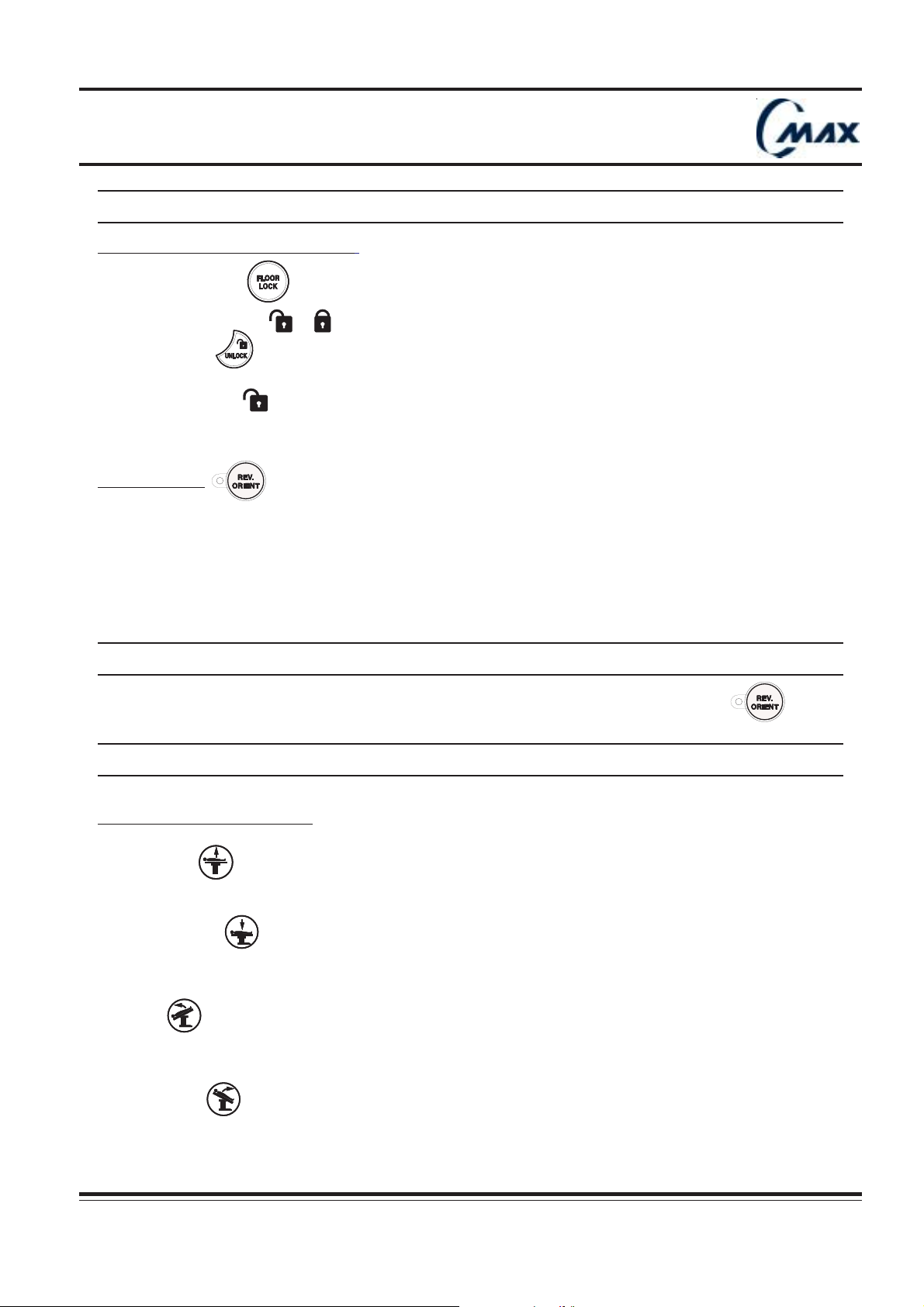
To unlock the table, proceed as follows :
1. Press FLOOR LOCK
LCD message (1) : «Press or » appears at the LCD message window.
2. Press UNLOCK
LCD status indicator : comes on.
During time lapse from lock mode, to effective unlock mode, “UNLOCKING” appears at the LCD message window.
4. REV. ORIENT
For few specific positioning (refer to patient positioning, chap 7.10 : Shoulder surgery), the table can be used in
reverse configuration.
When REV. ORIENT. key is activated, all other commands automatically take into account new patient head position ;
direction of Trendelenburg and lateral tilt movements are automatically reversed. BACK and LEG movements are
automatically permutated.
Flex and reflex movements are not available.
The information displayed on LCD are not reversed.
!!
!
!!
When REVERSE ORIENTATION function is effectively activated, the REV. ORIENT. diode is on.
To deactivate the REVERSE ORIENTATION function, press again REV.ORIENT. key.
When table is turned off, table memorizes orientation status.
Before any new positioning, ensure table is correctly configured in relation to patient orientation function.
!!
!
!!
TABLE TOP MOVEMENT KEYS
5. HEIGHT UP
By pressing HEIGHT UP, tabletop moves up. Display HEIGHT stroke value (3) moves accordingly.
6. HEIGHT DOWN
By pressing HEIGHT DOWN, tabletop moves down. Display HEIGHT stroke value (3) moves accordingly.
7. TREND
By pressing TREND., tabletop moves into Trendelenburg position. Display TREND value (4) moves accordingly.
8. REV. TREND
By pressing REV.TREND., tabletop moves into reverse Trendelenburg position. Display TREND. value (4) moves
accordingly.
CMAX NU 01F
Operator manual Réf. 022710201
29
Page 30
Operating table
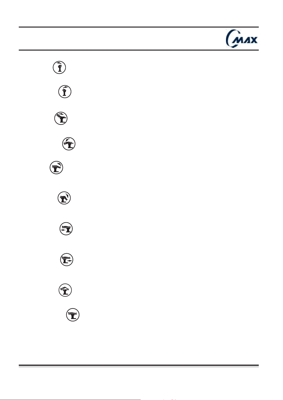
9. TILT LEFT
By pressing TILT LEFT, tabletop tilt towards Patient’s left side. Display LATERAL TILT value (5) moves accordingly.
10. TILT RIGHT
By pressing TILT RIGHT, tabletop tilt towards Patient’s right side. Display LATERAL TILT value (5) moves accordingly.
11. BACK UP
By pressing BACK UP, tabletop back section moves up. Display BACK SECTION value (6) moves accordingly.
12. BACK DOWN
By pressing BACK DOWN, tabletop back section moves down. Display BACK SECTION value (6) moves accordingly.
13. LEG UP
By pressing LEG UP, tabletop leg section moves up. Display LEG SECTION value (7) moves accordingly.
When leg section is removed, leg section value disappears.
14. LEG DOWN
By pressing LEG DOWN, tabletop leg section moves down. Display LEG SECTION value (7) moves accordingly.
When leg section is removed, leg section value disappears
15. SLIDE HEAD
By pressing SLIDE HEAD, tabletop moves towards head end. Display SLIDE value (9) moves accordingly.
When slide returns to “O” central position, movement stops for one second, then starts again.
16. SLIDE FOOT
By pressing SLIDE FOOT, tabletop moves towards foot end. Display LEG SECTION value (8) moves accordingly.
When slide returns to “O” central position, movement stops for one second, then starts again.
17. KIDNEY UP
By pressing KIDNEY UP, kidney elevator moves up. Display KIDNEY “T” symbol (9) comes on.
18. KIDNEY DOWN
By pressing KIDNEY DOWN, kidney elevator moves down. Display KIDNEY “T” symbol (9) disappears when it is back
to “O” position.
30
Réf. 022710201
Operator manual
CMAX NU 01F
Page 31
Operating table
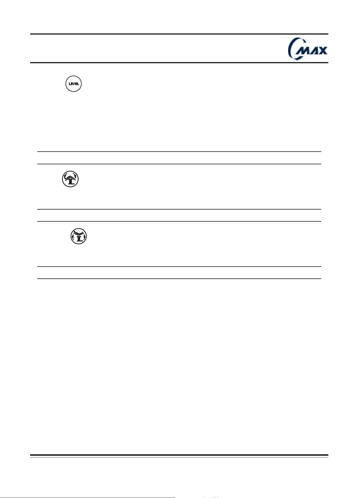
19. LEVEL
By pressing LEVEL, tabletop is gradually returned to horizontal position by aligning tabletop sections in the following
order :
1. Kidney and Lateral tilt
2. Trend and Back
3. Leg
Corresponding movement value varies accordingly on display.
When REVERSE ORIENTATION is activated, level function does not include back section for compliance
!!
with anesthesia procedures.
!
!!
20. FLEX
By pressing FLEX, back section moves down and tabletop moves into reverse Trendelenburg position.
Corresponding movement value varies accordingly on display.
In reverse configuration, Flex function is not available for patient safety reasons. “REV. ORIENT.” appears at
!!
!
!!
the LCD message window.
21. REFLEX
By pressing REFLEX, back section moves up and tabletop moves into Trendelenburg position.
Corresponding movement value varies accordingly on display.
In reverse configuration, reflex functions are not available for patient safety reasons. “REV. ORIENT.” appears
!!
!
!!
at the LCD message window.
22. For the slide and heigth indication, it is possible to change the vlues displayed from inches to centimeters (or from
centimeters to inches) by pressing simultaneously LEVEL and FLEX buttons just after switch on, within the 5 first
seconds.
CMAX NU 01F
Operator manual Réf. 022710201
31
Page 32
Operating table
6.2 - ALS description :
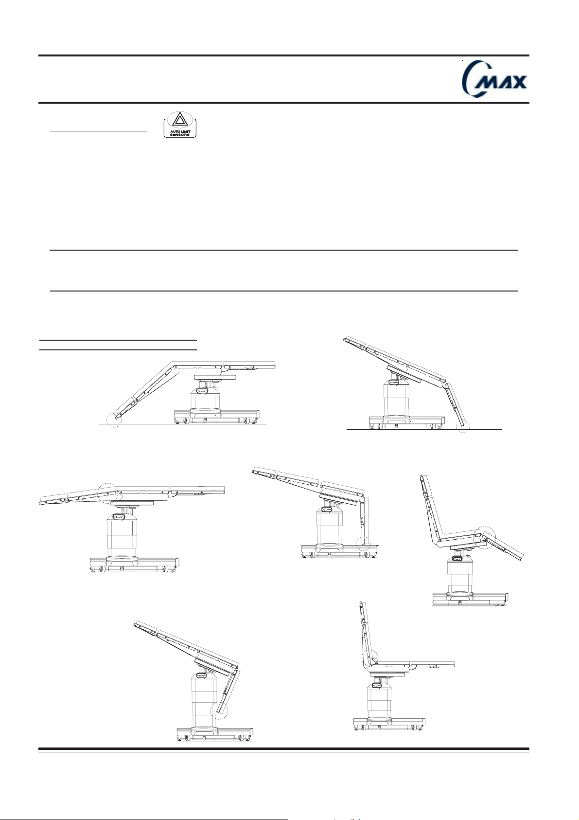
C-MAX smart electronic design using built-in sensors, provide safety information to the users. These sensors prevent
sectional conflict and detect accidental table collisions with external obstructions (AUTO LIMIT SENSORS : pending
patent).
To prevent sectional conflict, or collision with table or floor, ALS system immediately stops movement in process.
ALS Diode lights up. (page 27, 10)
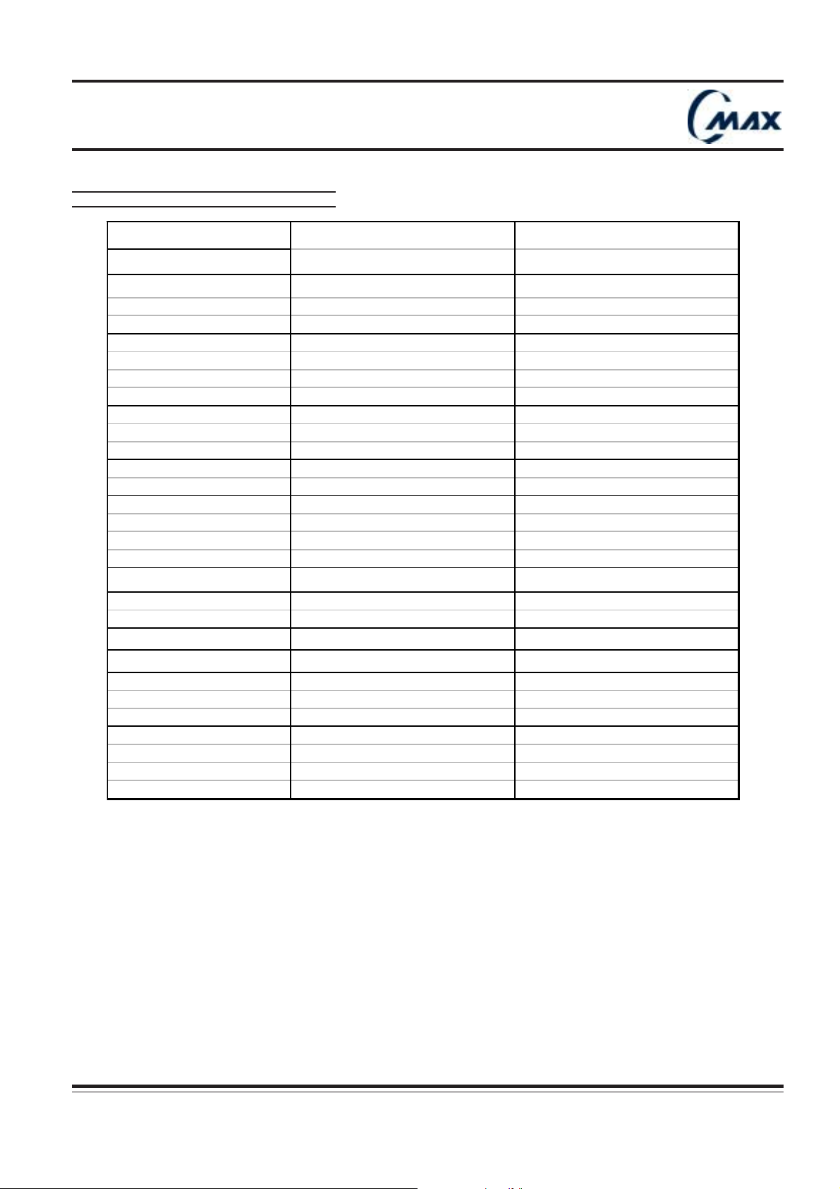
To continue movement in process, the suggested alternative table movement appears at the LCD message window.
NB : The suggested alternative movement is not the only one possible.
Caution : these ALS suggested alternative table movements do not take into account the type of surgery being
!!
!
conducted or the environment (e.g. : other equipment close by) and might not be compatible with the surgical
!!
procedure in process.To avoid any risk and before carrying out the suggested alternative, the user should
evaluate feasibility.
FIG. 6.2 - COLLISIONS
C-MAX29
C-MAX31
C-MAX 33
C-MAX30
C-MAX 34
32
C-MAX36
Réf. 022710201
C-MAX35
CMAX NU 01F
Operator manual
Page 33
Operating table
FIG. 6.3 - ALS RECOMMENDATIONS
OP ERAT ION POT ENT IAL CO LLIS ION RECOMM ENDAT IO N
Norma l orientation
Height dow n
Slide head
Slide foot
Leg up
Leg down
Leg sec tion/ base TREND
Leg secti on/ floor LEG UP
Headre st / flo or REV TREND
Leg secti on/ slide LEG UP
Leg sec tion/ base TABLE UP
Leg secti on/ floor LEG UP
Leg secti on/ colum n TREND
Back section/slide BACK UP
Leg sec tion/ base TREND
Leg secti on/ floor TREND
Leg secti on/ floor TABLE UP
Leg sec tion/ base TABLE UP
Leg sec tion/ base TABLE UP
Leg secti on/ floor TABLE UP
Leg secti on/ slide SLIDE FOOT
Leg secti on/ colum n TREND
Ba c k u p
Back d own
Kidney up
Trend
Rev. Trend.
Tilt (le ft or right)
Kidney elevator/Back s ect ion KIDNEY DOW N
Headrest/floor TABLE UP
Back section/slide SLIDE HEAD
Kidney elevator/Back s ect ion BA CK DOWN
Headrest/floor TABLE UP
Leg secti on/ floor TABLE UP
Leg sec tion/ base TABLE UP
Leg secti on/ colum n TREND
Leg secti on/ floor TABLE UP
Leg sec tion/ base TABLE UP
Leg secti on/ colum n TABLE UP
Headrest/floor TABLE UP
CMAX NU 01F
Operator manual Réf. 022710201
33
Page 34
Operating table
6.3 - Optional foot control operations :
Refer to chapter 5.9 to connect the foot control to the table.
1. Lock table : tabletop movements are not allowed when table is unlocked.
2. Ensure table is correctly configured in relation to patient orientation function.
6.4 Tabletop pads
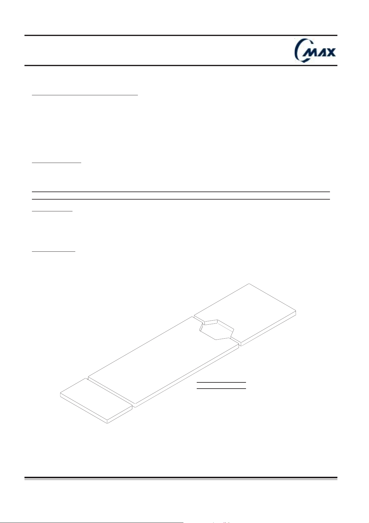
FUSION conductive tabletop pads have to be ordered separately.
Pad set is comprised of three components.
!!
!
!!
Use exclusively recommended FUSION pads.
Installing pads :
1. Remove the pad from its bag.
2. Position pad on the section. Press pad and table top sections Velcro strips together.
Removing pads :
FIG. 6.4 - PADS
34
Réf. 022710201
CMAX NU 01F
Operator manual
Page 35
Operating table
Ensurecapscover
socketswhennotinuse.
SERVE
C-MAX 10
2
1
CLICK
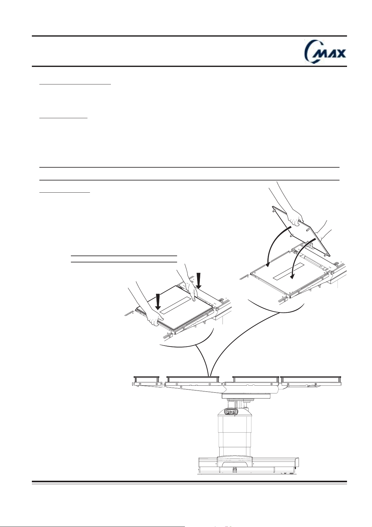
6.5 - Optional Xray top :
This accessory is available for the use of X-ray cassette film.
Xray double top set is comprised of four components (FIG. 6.4)
Installing Xray top :
1- Remove X-ray top sections from their box.
2- Remove pads from the tabletop.
3- Position X-ray top section onto corresponding tabletop section and make standoffs fit inside mounting holes
(see drawing).
4- Reinstall pads.
Ensure that it has been correctly secured, by pulling lightly double top up.
!!
!
!!
Removing Xray top :
1- Remove pads from Xray top
2- Pull away X-ray top upwards and stow it with care.
3- Install pads on tabletop.
FIG. 6.5 - INSTALLING X-RAY TOP
CMAX NU 01F
Operator manual Réf. 022710201
35
Page 36

Operating table
36
Réf. 022710201
CMAX NU 01F
Operator manual
Page 37
Operating table
7 - Patient positioning :
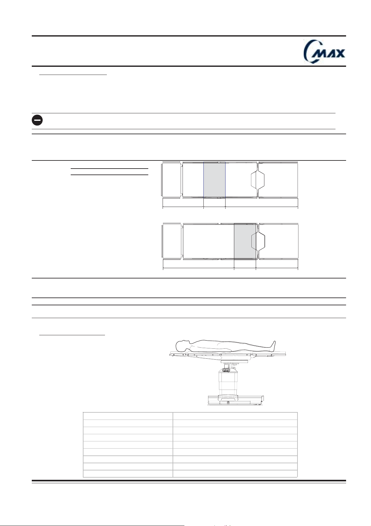
C-MAX is suitable for most surgical procedures and designed to support patient weighing up to 600 lbs (270kg), in
standard positions defined hereafter.
The C-MAX top slide provides full body imaging (FIG. 7.1) and avoids patient reorientation (except for shoulder
arthroscopy with shoulder chair accessory).
Do not exceed 600 lbs (270 kg) patient weight, using standard positions specified hereafter in chapter 7.
If a heavy patient (500-600 lbs) / (230-270 kg) is placed on the tabletop in full slide towards patient head end,
!!
!
!!
caution should be used to avoid bumping the table, which can cause the table to tip. If chest compressions or
other forces need to be applied on a 500-600 lbs (230-270 kg) patient, the patient should be centered over the
column.
FIG. 7.1 - X-RAY ACCESS
13”
43”
(1090mm)
25”
(637mm)
25”
(635mm)
43”
(1088mm)
The positionings described below are given as an example only. They do not replace instructions that must be
given by the health care profesionals in charge of the patient to prevent patient injury.
!!
!
!!
Accessories here-below are not systematically represented.
Possible patient or user injury may result from using accessories manufactured and sold by other companies.
!!
!
!!
7.1 Surgical procedure : Eye, E.N.T., facial plastic, open heart, abdominal vascular.
13”
(330mm)
(330mm)
Ensurecapscover
socketswhennotinuse.
SERVE
C-MAX 24a
Patient is positioned in supine.
Tabletop is centered in relation to the table column.
Recomm e nd e d equipm ent
636900121/120 Flex ible (rigid anes thesia s creen (x1)
686900122 Eas y c l amps (x2)
686900114 St andard armboards (x2)
686900117 Restraint strap (x 1)
Option
542200818 Xray top
CMAX NU 01F
Operator manual Réf. 022710201
686900118 Footrest
URO18
37
Page 38
Operating table
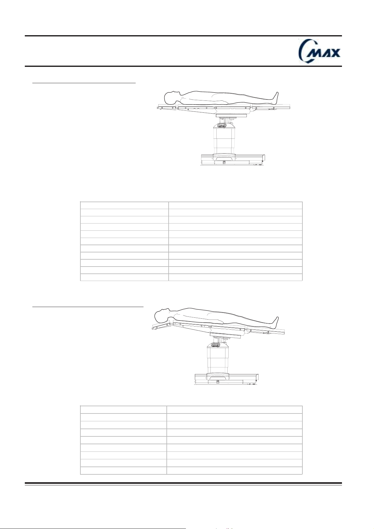
7.2 Surgical procedure : Ophtalmology
Ensurecapscover
socketswhennotinuse.
SERVE
URO18
Patient is positioned in supine. Tabletop is centered in relation to table column and an extremely low height position
can be obtained.
For surgeon convenience, an optional narrow headrest can be installed (refer to narrow headrest user’s
instructions).
Recomme nded e qui pm ent
686900103 Narrow he adrest (x1)
542200203 Head res t ada pt er (x 1 )
686900121/ 120 Flexibl e / rigi d a nest hesia sc reen (x1)
686900122 E a s y c l am ps (x2)
686900114 St and ard arm boa rds (x 2)
686900117 Rest raint st rap (x1)
Option
542200818 Xray t op (x1)
686900104 Narrow wristres t (x1 )
7.3 Surgical procedure : Neck surgery
Ensurecapscover
socketswhennotinuse.
SERVE
URO24a
Patient is positioned in supine.
Tabletop is centered in relation to table column. Flex is given by using reverse trendelenburg and lowering
headrest.
Recomme nde d equipment
686900121/120 Flex ibl e /rigid anesthes i a sc reen (x 1)
686900122 Eas y clamps (x2)
686900114 St andard armboards (x2)
686900117 Rest raint strap (x1)
38
Option
542200818 Xray t op
686900118 Foot res t
Réf. 022710201
CMAX NU 01F
Operator manual
Page 39
Operating table
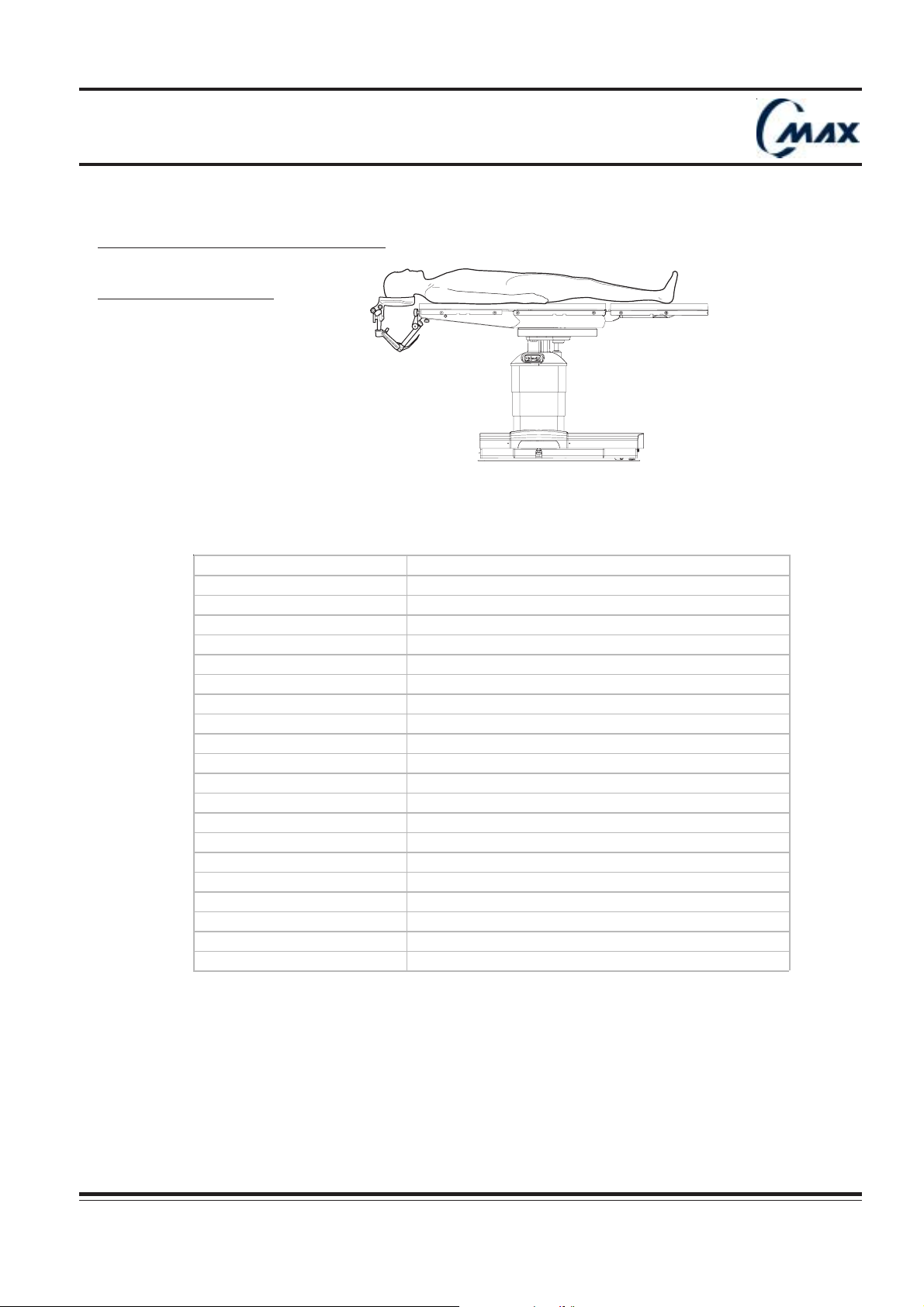
7.4 Surgical procedure : Cranial surgery
a) Prone or supine position
Ensurecapscover
socketswhennotinuse.
SERVE
URO22
Patient is positioned in supine or in prone position.
Tabletop is centered in relation to table column.
Optional surgical headrests can be installed, according to the surgeon’s needs (refer to Neurosurgical headrest
user’s instructions).
Recommende d equipm e nt
686900025 Basi c unit
686900026
686900027 Swivel adapter
686900025 Basi c unit
686900028
686900027 Swivel adapter
686900029 Adult s kull pi ns
Horseshoe he adrest - adult model
Or
Skull clamp hea dre st - adult model
542200203 St andard headrest adapt er
636900121/120 F l exible /rigid anes thesi a sc reen (x1)
686900122 Eas y c l am ps (x2)
686900114 Standard armboards (x2)
686900117 Rest raint s t rap (x 1)
Option
542200818 X-ray top
686900030 Child s kull c l am p pins
686900031 Neurosurgic al horseshoe headres t - child m odel
CMAX NU 01F
Operator manual Réf. 022710201
39
Page 40
Operating table
URO26
Ensurecapscover
socketswhennotinuse.
SERVE
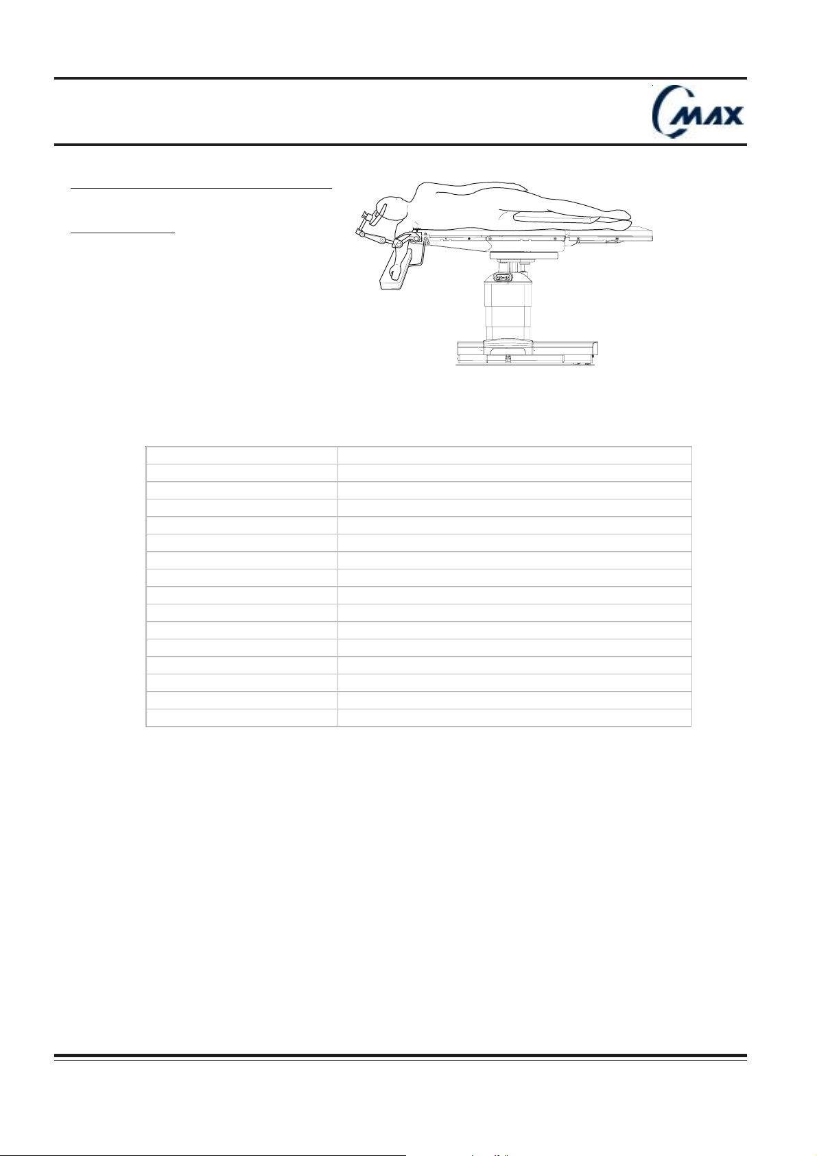
7.4 Surgical procedures : Cranial surgery
b) Lateral position
Patient is positioned in lateral position. Tabletop is centered in relation to table column.
Optional neurosurgical headrests can be installed according to surgeon needs (refer to Neurosurgical headrest
user’s instructions).
Recommended equipm ent
686900025 Bas i c unit
686900027 Swivel adapter
686900028 Neurosurgical s kull c l am p headres t - adult model
686900029 Adult skull pi ns
542200203 Headres t adapt er
686900117 Rest raint s t rap (x 1)
686900122 Easy c l am ps (x4)
686900128 Universal armboards (x 2)
636900121/120 Flex i bl e / ri gid anes thes ia sc reen (x 1)
Option
542200818 X-ray top
686900030 Sk ul l clamp pi ns - child m odel
40
Réf. 022710201
Operator manual
CMAX NU 01F
Page 41
Operating table
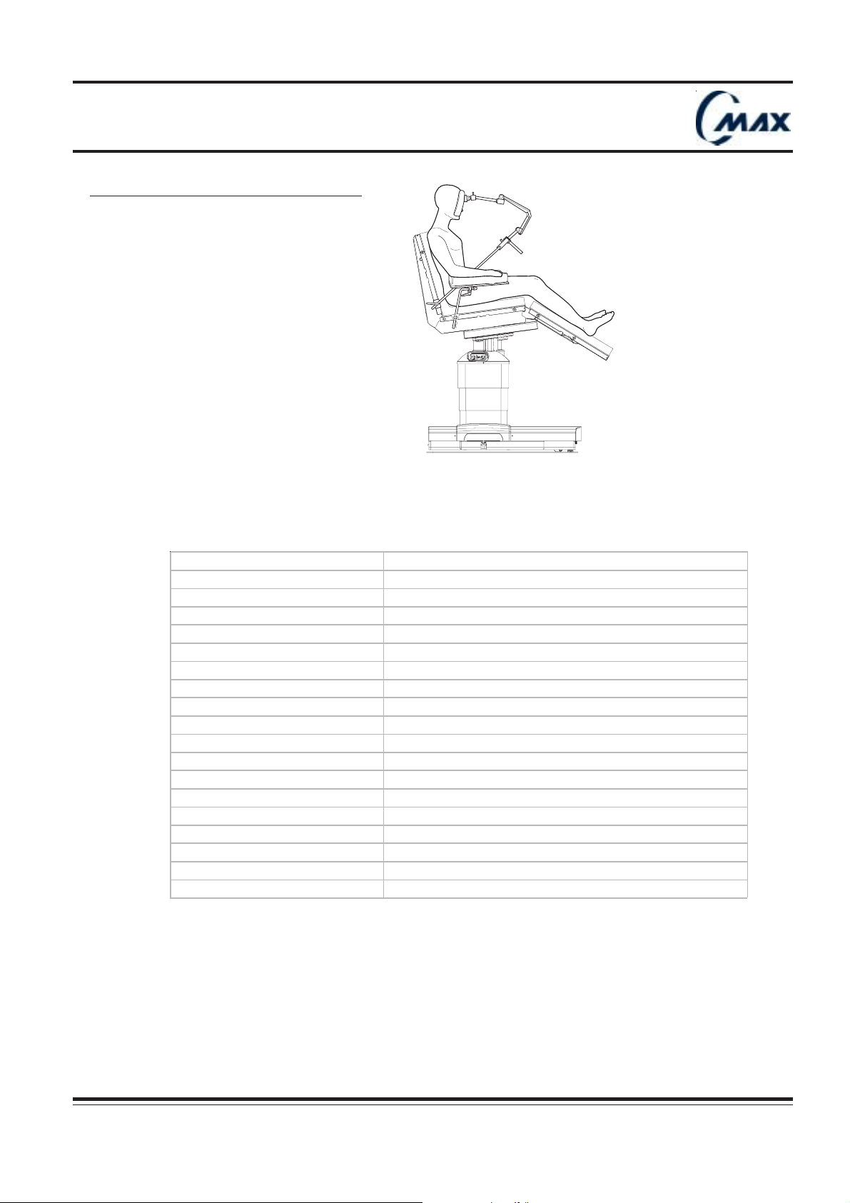
7.5 Surgical procedures : Cranial surgery
Ensurecapscover
socketswhennotinuse.
SERVE
URO17
Patient is positioned in sitting position. Table top is slid 4 inches (about 100 mm) towards head end and moved
10° in Trendelenburg. Back section is approx.75° up and leg section approx. 20° down.
In this case C-MAX offers large clearance from the base.
Optional neurosurgical head rests can be installed according to the surgeon’s needs (refer to Neurosurgical
headrest user’s instructions).
Recommende d equipm ent
686900025 Bas i c unit
686900026
686900027 S wivel adaptor
686900025 Bas i c unit
686900027 S wivel adapter
686900028
686900029 Adult s k ul l pins
686900133 Headrest adapt er for si t ting pos ition
686900117 Rest raint strap (x1)
686900122 Eas y c l amps (x 2)
686900128 Univers al arm board (1)
Option
686900031 Neurosurgic al hors eshoe headrest - child m odel
68690030 Child s kull c l am p pins
Horseshoe headre st - adult model
OR
Neurosurgi ca l skull clamp hea dre st - a dul t model
CMAX NU 01F
Operator manual Réf. 022710201
41
Page 42
Operating table
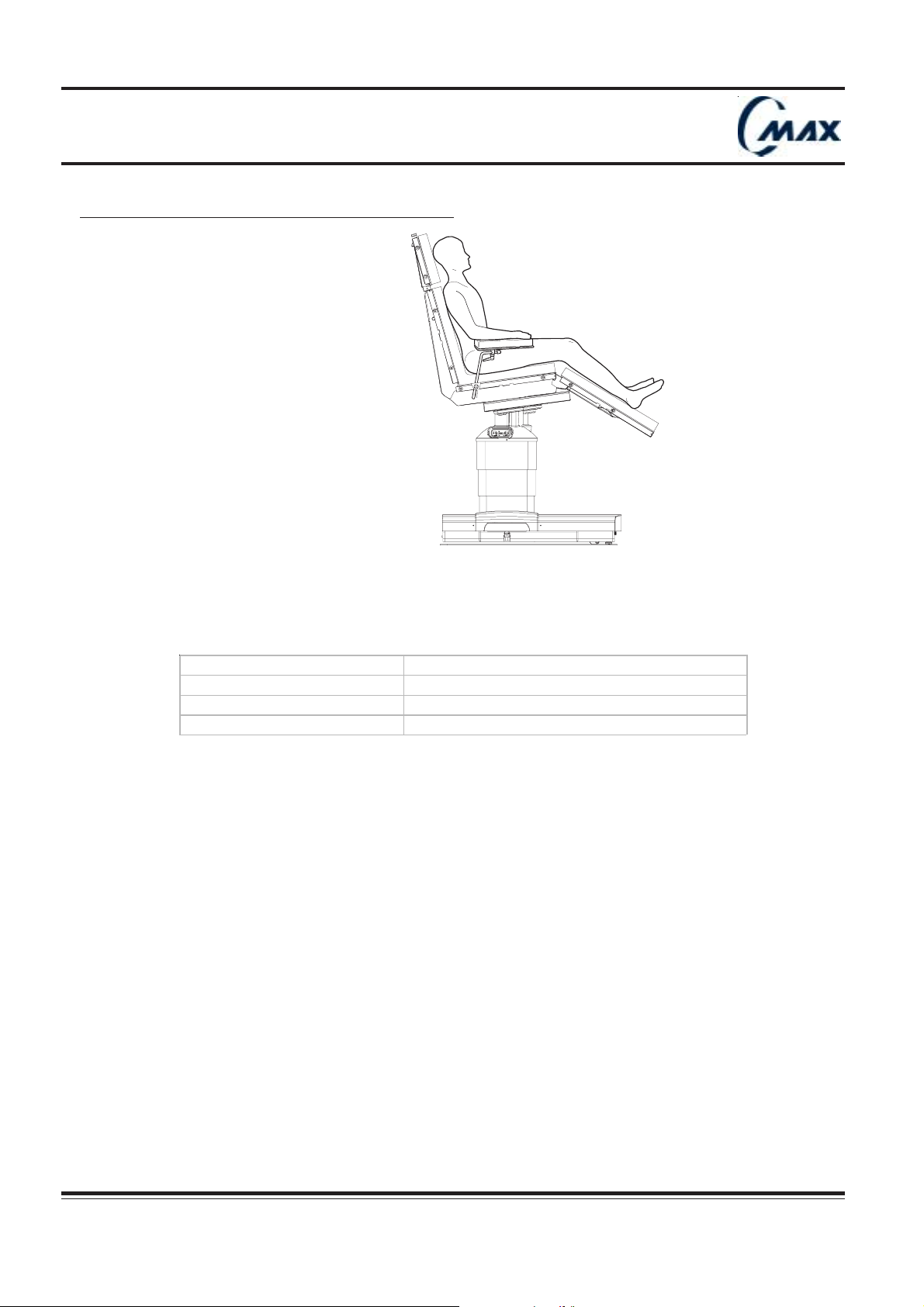
7.6 Surgical procedures : Plastic and breast surgery
Ensurecapscover
socketswhennotinuse.
SERVE
URO 16
Patient is positioned in sitting position. Tabletop is slid 4 inches (about 100 mm) towards head end and moved
10° in Trendelenburg.
Back section is approx. 75° up and leg section approx. 20° down.
In this case, C-MAX offers a large clearance from the base.
Recom m ende d equipm ent
686900117 Res traint s trap (x1)
686900122 Easy clam ps (x1)
686900128 Universal arm board (1)
42
Réf. 022710201
CMAX NU 01F
Operator manual
Page 43
Operating table
Ensurecapscover
socketswhennotinuse.
SERVE
URO25
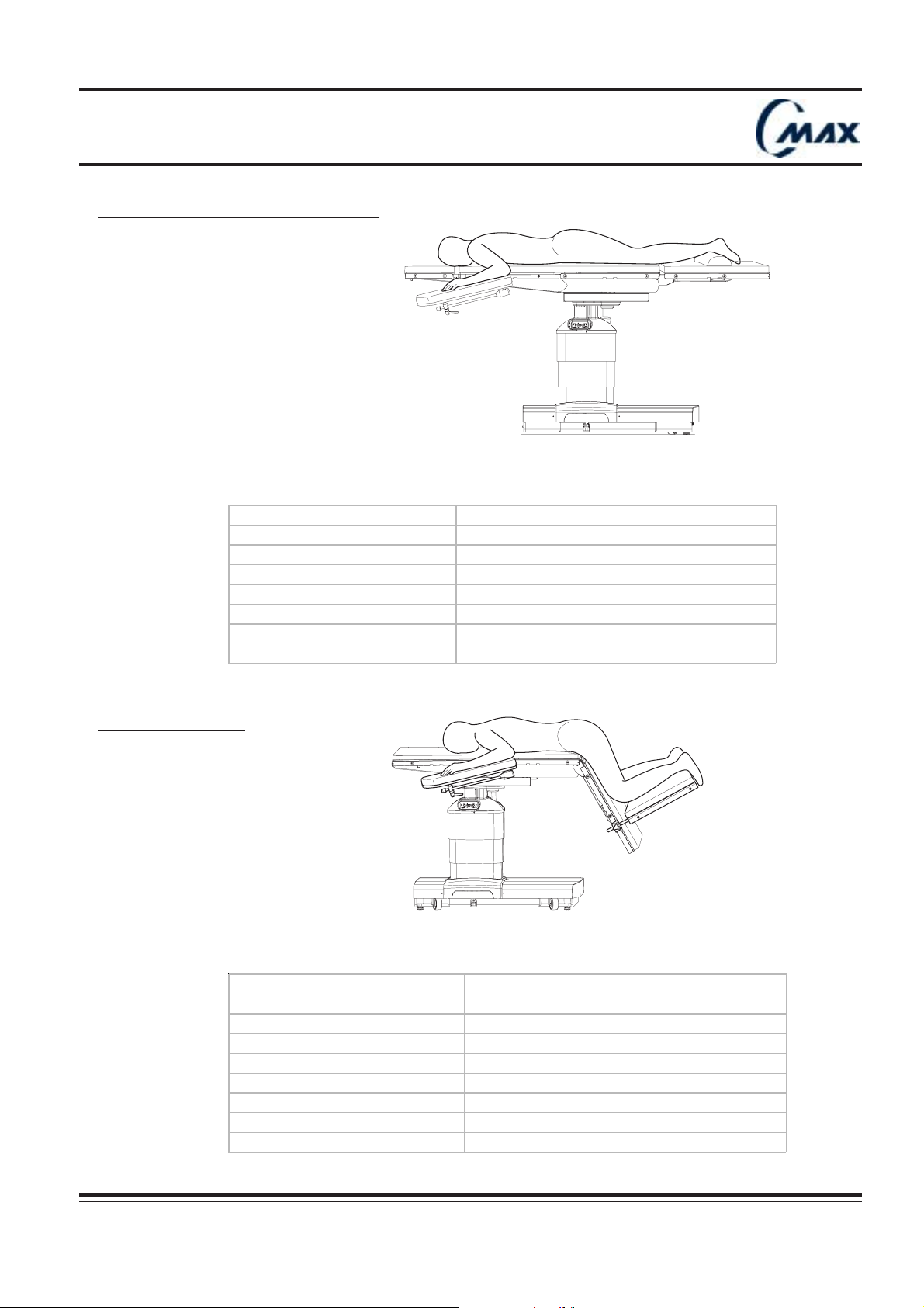
7.7 Surgical procedure : Spinal surgery
a) Prone position
Patient is positioned in the prone position. Tabletop is centered in relation to table column.
Recommende d equipm e nt
686900117 Rest raint strap (x2)
686900122 Eas y c l amps (x4)
686900128 Universal armboard (x 2)
686900121/120 Flexibl e/ rigi d anesthesia s creen (x1)
Option
542200818 X-ray top
b) Knee-chest position
Ensurecapscover
socketswhennotinuse.
SERVE
URO28
Tabletop is slid towards foot end.
Patient is positioned in knee-chest position, using Andrews frame or equivalent accessory.
Recommende d equipm e nt
686900117 Restraint strap (x 2)
686900122 Easy clamps (x4)
686900128 Univers al arm board (x 2)
686900121/120 Flexible/rigid anes thesi a s creen (x1)
542200910 Spinal frame
Option
542200818 X-ray t op
CMAX NU 01F
Operator manual Réf. 022710201
43
Page 44
Operating table
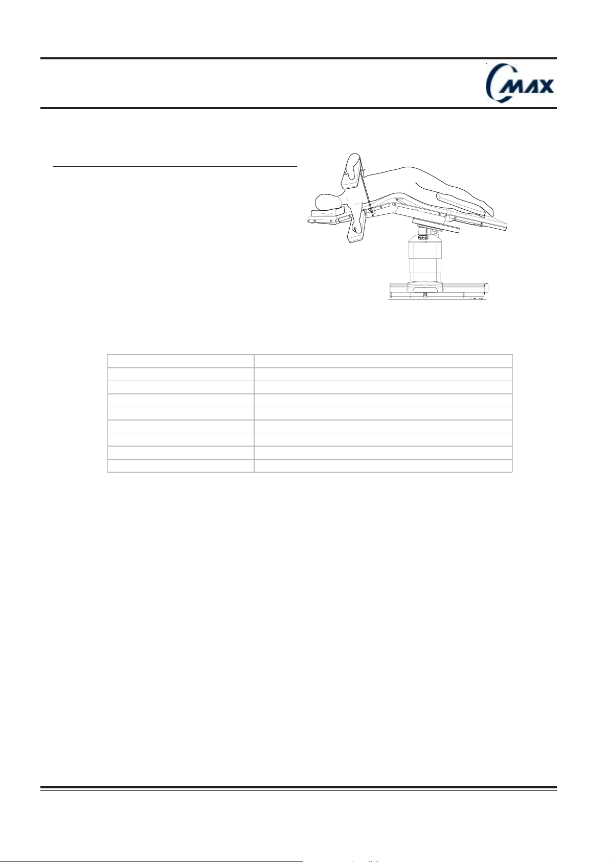
7.8 Surgical procedure : Kidney & Thoracic surgery
Ensurecapscover
socketswhennotinuse.
SERVE
Patient is positioned in lateral position. Tabletop is slid towards head end with flex, between back and seat
section. Kidney elevator can be used to increase flex.
Recommende d equipm ent
686900114 St andard armboard (x1)
686900117 Rest raint s t rap (x 1)
686900122 Eas y c l am ps (x3)
686900128 Univers al armboard (x 1)
686900121/120 Flexible/rigid anes thes ia sc reen (x 1)
URO27
Option
542200818 X-ray top
44
Réf. 022710201
CMAX NU 01F
Operator manual
Page 45
Operating table
Ensurecapscover
socketswhennotinuse.
SERVE
URO20
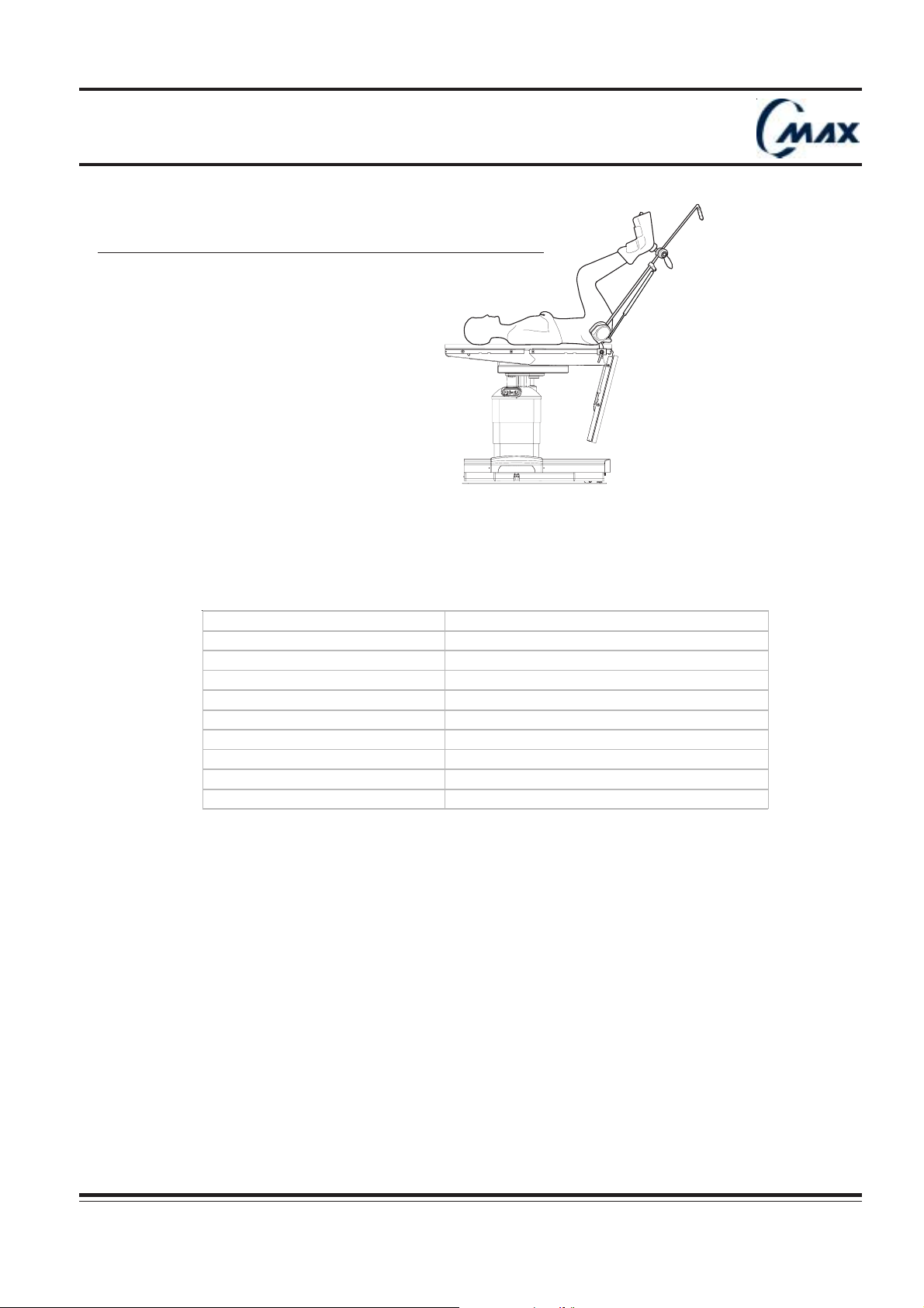
7.9 Surgical procedure : Urology, Proctology, and gynecology
Headrest is removed. Tabletop slid towards patient foot end.
Patient is positioned in supine position with patient’s legs placed in leg holders (refer to leg holders user’s
instructions).
Leg section is folded down or removed
Recommende d equipm e nt
686900121/120 Flexible/rigid anes t hesia sc reen (x1)
686900122 Easy clamps (x2)
686900114 Standard armboard (x2)
686900117 Restraint s trap (x1)
686900103 Pair of leg holders
Option
542200818 X-ray t op
686900105 Transfer board
CMAX NU 01F
Operator manual Réf. 022710201
45
Page 46
Operating table
URO29
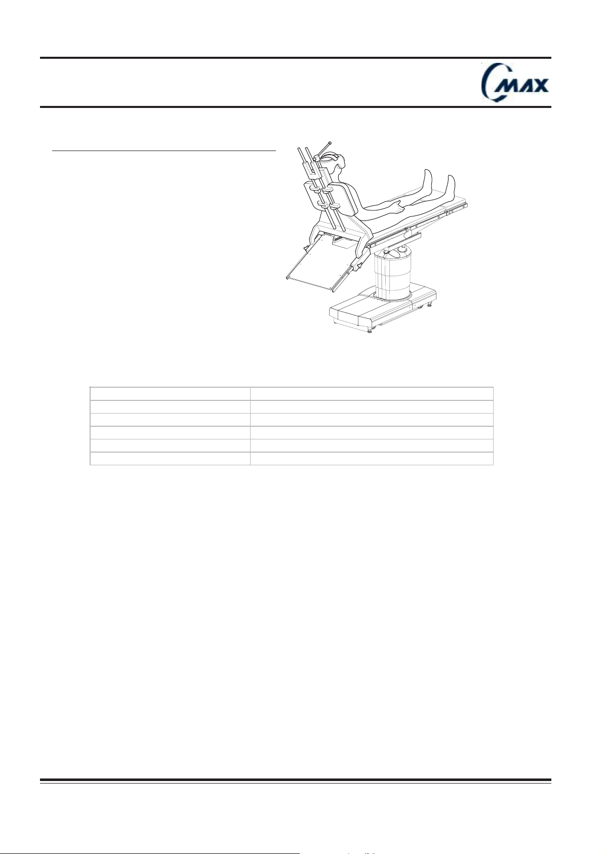
7.10 Surgical procedure : Shoulder arthroscopy
Shoulder chair accessory is positioned on the table prior to patient installation (refer to shoulder chair’s user’s
instructions).
Patient is positioned in reverse orientation.
Recommende d equipm ent
686900108 Shoulder chai r wit h l at eral s upport
686900117 Rest raint s t rap (x 1)
686900122 Easy c l am ps (x3)
686900128 Univers al arm board (x1)
686900121/120 Flex i bl e/ ri gid anesthesia s creen (x1)
46
CMAX NU 01F
Réf. 022710201
Operator manual
Page 47
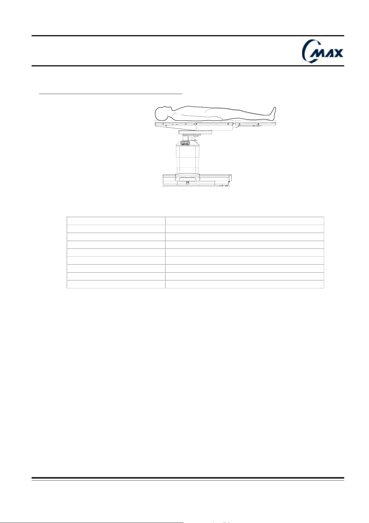
Operating table
7.11 Surgical procedure : Vascular & Angioplasty
Ensurecapscover
socketswhennotinuse.
SERVE
URO19
Headrest removed. Tabletop is slid towards foot end. Patient is positioned in supine position. Footrest used as
extension (refer to foot rest user’s instructions) can be installed for tall patient.
Recommende d equipm e nt
686900114 St andard armboard (x2)
686900117 Rest raint s t rap (x 1)
686900118 Footrest
686900122 Eas y c l am ps (x2)
686900121/120 Flex i bl e/ ri gid anes thes ia sc reen (x 1)
Option
542200818 X-ray top
CMAX NU 01F
Operator manual Réf. 022710201
47
Page 48
Operating table
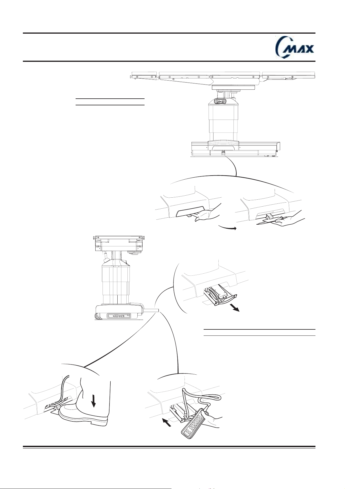
FIG. 8.1 : FOOT PUMP
Ensurecapscover
socketswhennotinuse.
SERVE
C-MAX 05
48
C-MAX 06
W0109-2000-SW
FDLKM-C.MAX
WARNING
WARNING
AVERTISSEMENT
AVERTISSEMENT
CHARGE BATTERY
INTELLI POWER
1
FIG. 8.2 : OVERRIDE HAND CONTROL
3
2
CMAX NU 01F
A
Réf. 022710201
Operator manual
Page 49
Operating table
- Pull pad away from tabletop section.
8 - Override system :
Description :
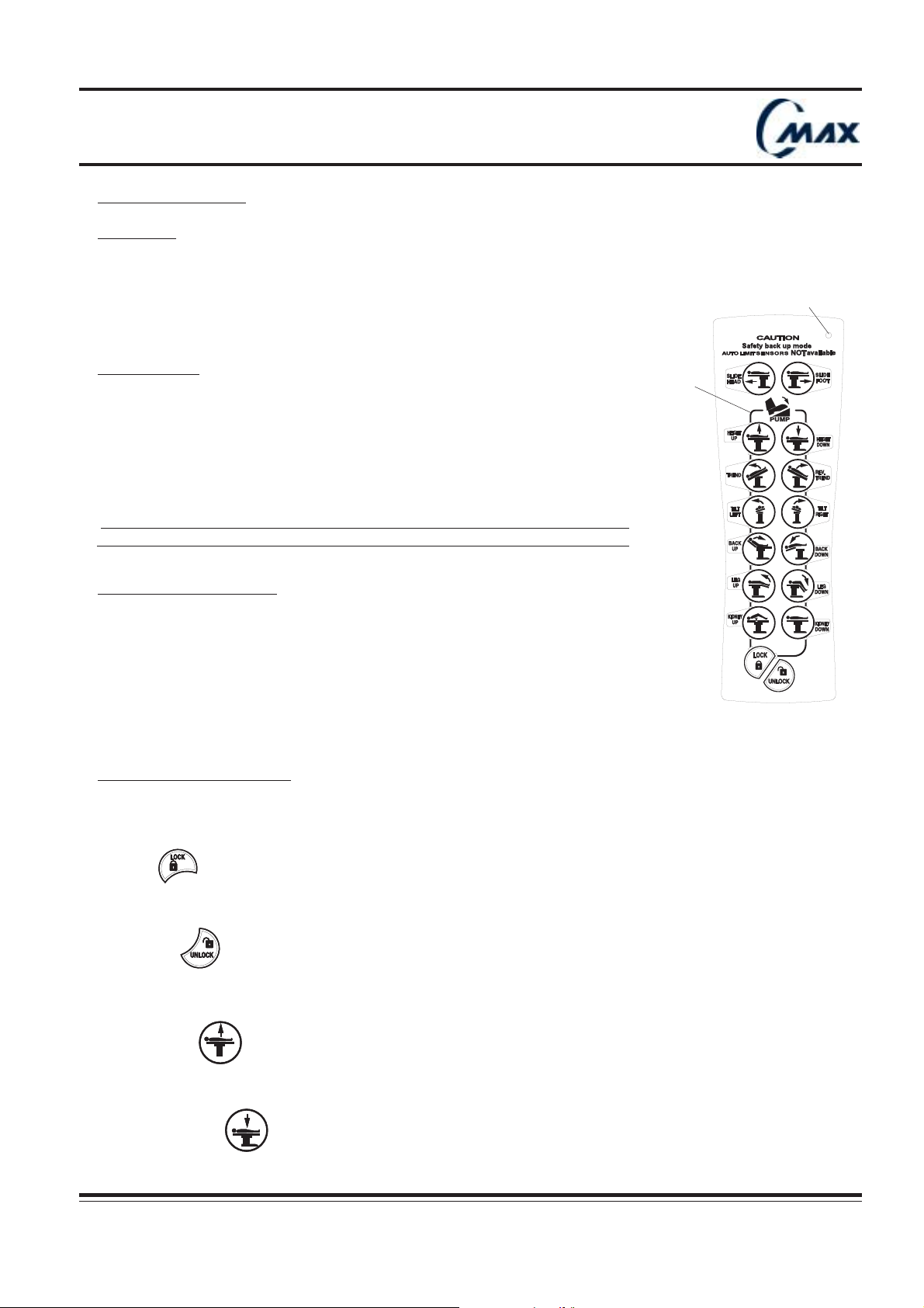
C-MAX surgical table is equipped with an override systems to be used in case of major electronic failure.
This override system is located at the table base level, right side, and is comprised of :
- a foot pump to provide hydraulic power
- an override hand control to select movement to be activated.
Green diode
Residual risks :
- In case of all unexpected situations, press “OFF” key to stop the table.
- In case of unexpected simultaneous movements, release the key.
- In case of no movement obtained :
a) Read hand control LCD message window and follow recommendations.
b) Press “OFF” key and press any key to switch on hand control.
c) If none of these actions solve the problem, use the override system.
!!
!
!!
In all these cases, contact your local service representative for maintenance.
8.1 Operating instructions
1. Flip pedal down (FIG. 8.1).
2. Pull drawer out and grasp the override hand control (FIG. 8.2).
3. Replace the drawer.
4. Pump pedal while pressing desired movement key on the override hand control.
For “UNLOCK” and “SLIDE” movements it is not necessary to pump.
NB : By pressing any key, the main hand control automatically switches off after 1 second.
Description of function keys :
The desired operation can be activated by pressing any single key of the override hand
control.
When a key is pressed, green diode, located on upper part of keyboard, lights up.
Pump line
1. LOCK
By pressing LOCK and pumping simultaneously, floor blocks are gradually engaged.
To ensure table has been correctly secured on the floor, gently push table.
2. UNLOCK
By pressing UNLOCK only, floor blocks are gradually disengaged.
To ensure floor blocks have been completely disengaged, gently push table.
3. HEIGHT UP
By pressing HEIGHT UP and pumping simultaneously, tabletop moves up.
4. HEIGHT DOWN
CMAX NU 01F
Operator manual Réf. 022710201
49
Page 50
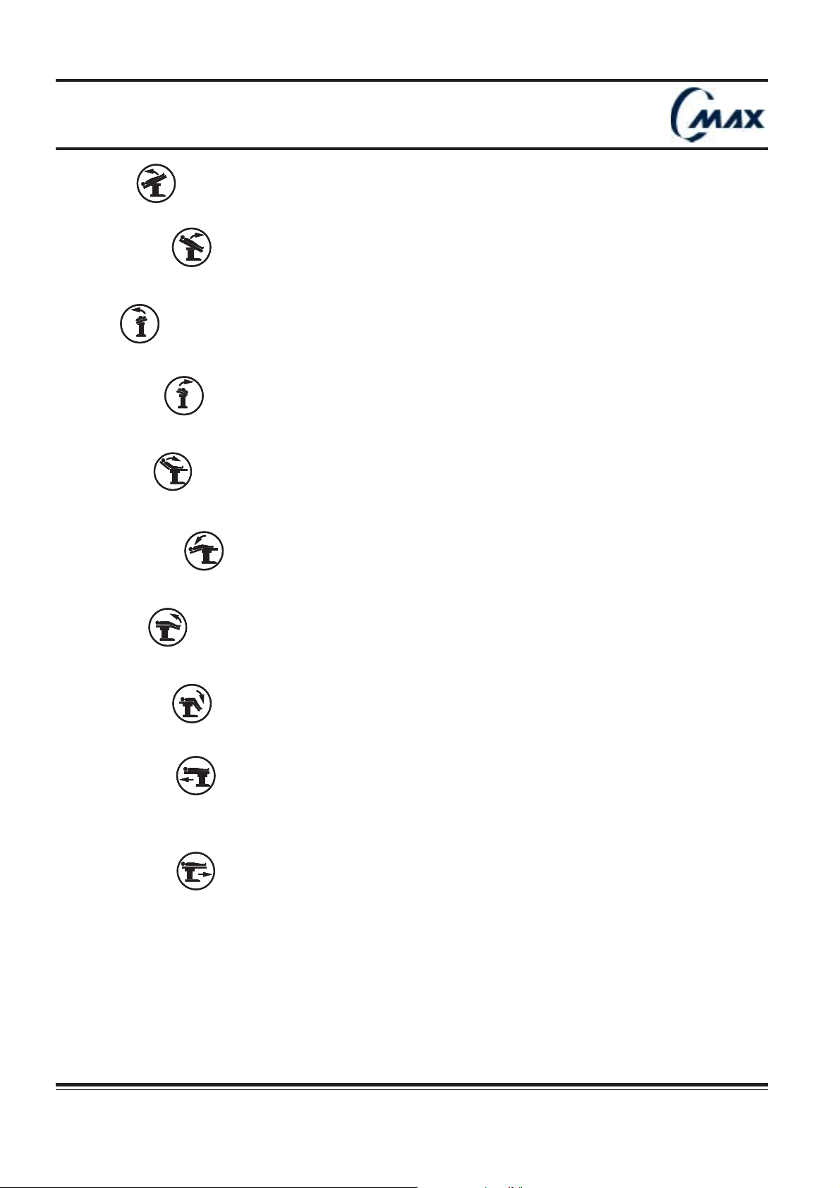
Operating table
By pressing HEIGHT DOWN and pumping simultaneously, tabletop moves down.
5. TREND
By pressing TREND. and pumping simultaneously, tabletop moves into Trendelenburg position.
6. REV. TREND.
By pressing REV.TREND. and pumping simultaneously, tabletop moves into reverse Trendelenburg position
7. TILT
By pressing TILT LEFT and pumping simultaneously, tabletop tilt towards patient’s left side.
8. TILT RIGHT
By pressing TILT RIGHT and pumping simultaneously, tabletop tilt towards patient’s right side.
9. BACK UP
By pressing LEG UP and pumping simultaneously, tabletop back section moves up.
10. BACK DOWN
By pressing BACK DOWN, table top back section moves down.
11. LEG UP
By pressing LEG UP and pumping simultaneously, tabletop leg section moves up.
12. LEG DOWN
By pressing LEG DOWN and pumping simultaneously, tabletop leg section moves down.
13. SLIDE HEAD
By pressing SLIDE HEAD, tabletop moves towards head side.
It is not necessary to pump. This movement is electrically powered.
14. SLIDE FOOT
By pressing SLIDE FOOT, tabletop moves towards foot side.
50
Réf. 022710201
CMAX NU 01F
Operator manual
Page 51
Operating table
15. KIDNEY UP
By pressing KIDNEY UP and pumping sumultaneously, kidney elevator moves up.
16. KIDNEY DOWN
By pressing KIDNEY DOWN, kidney elevator moves down.
When override hand control is in use, primary hand control is automatically shut off, after 1 second.
!!
!
!!
In override mode, no sensor is available (A.L.S. off) : when articulating table top, take care to avoid
!!
section collision with table top (e.g. : when sliding), with table base or with the floor.
!
!!
In override mode, lock table before articulating table top.
!!
!
!!
There is no reverse orientation key in override mode. Controls are configured in normal orientation.
!!
!
!!
When table is turned to back up mode, table does not memorise orientation status.
Before articulating table top, take into account patient orientation. If patient is in Reversed Orientation
change TREND selection to REV. TREND., BACK SECTION to LEG SECTION, LEFT TILT to RIGHT TILT,
and vice versa.
8.2 Replacing override hand control :
1. Place override hand control face down in the right hand side of the drawer.
2. Wind up the cable in the left hand side of the drawer.
3. Push drawer back in.
4. Fold the pedal back.
Take care not to jam cable when replacing drawer.
!!
!
!!
CMAX NU 01F
Operator manual Réf. 022710201
51
Page 52
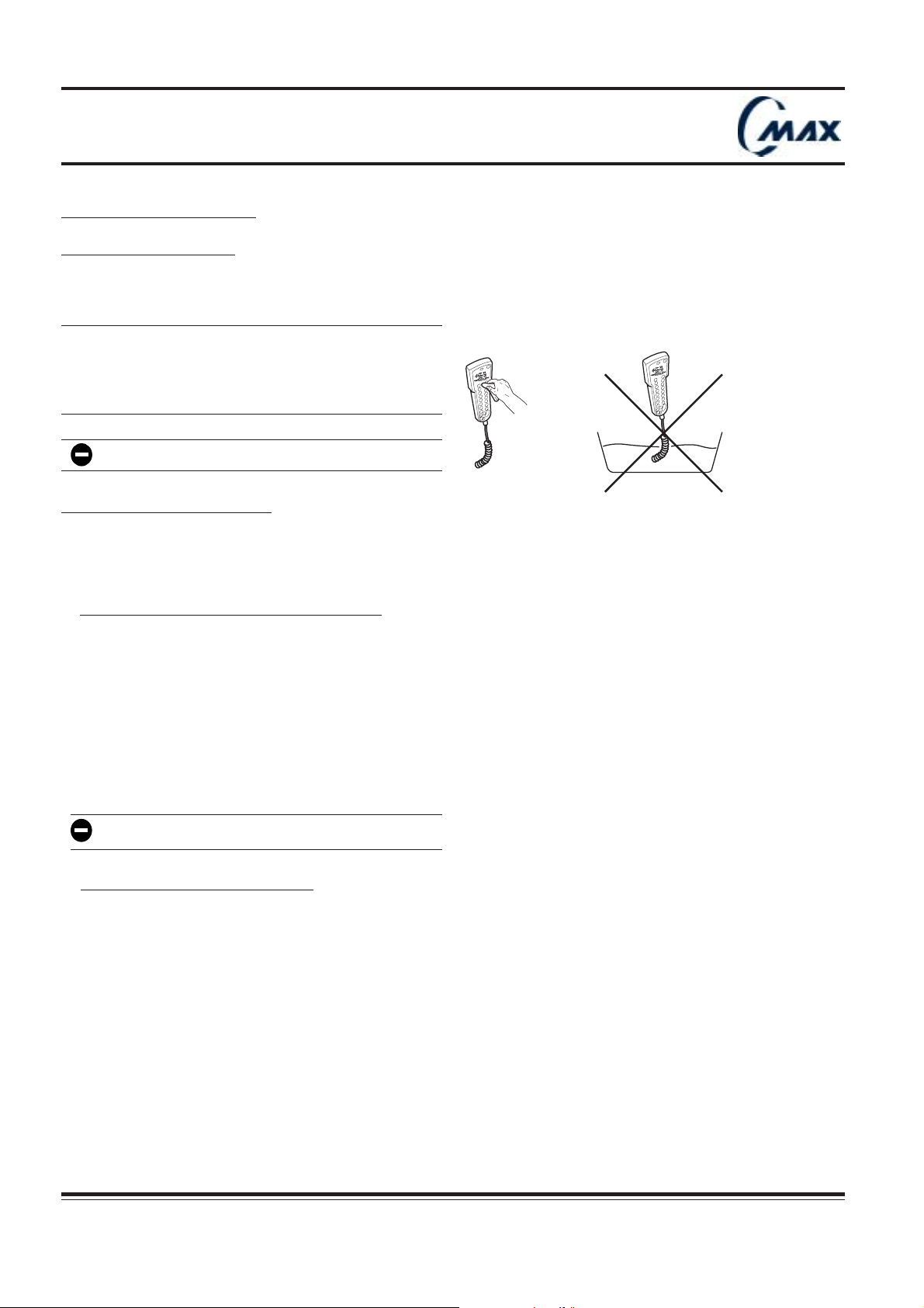
Operating table
9 - Cleaning and disinfecting
9.1 General instructions
When using cleaning and disinfecting products, be sure to strictly observe utilization precautions indicated by product
manufacturer.
Before any cleaning operation:
!!
!
!!
Switch off the table.
Disconnect the control unit.
Fit watertight covers on each connector.
"
3
0
T
¡
¡
4
0
0
-
2
T
L
TI
"
0
¡
0
0
0
!
D
A
D
E
N
E
H
R
T
E
D
¡
I
0
L
0
S
"
3
0
T
¡
¡
4
0
0
-
2
T
IL
T
"
0
¡
0
0
0
!
D
A
D
E
N
E
H
R
T
E
D
¡
I
0
L
0
S
Do not immerse hand control unit in liquid.
C-MAX 11
9.2 Cleaning and disinfecting
Use a ready-to-use detergent - disinfectant solution diluted as may be required. Be sure to observe dilution and temperature
instructions recommended by manufacturer. Check that the active constituents of the products used are compatible with
the materials implemented in manufacture of the FHSurgical products.
a) Cleaning between two surgical operations
Cleaning the control unit
- Disconnect the control unit.
- Wipe the control unit using a compress (or equivalent non-woven material) moistened with a detergent - disinfectant
solution.
- Allow to dry.
Cleaning visible surfaces of table
- Spray a detergent - disinfectant solution over all the visible surfaces (carefully avoiding cushion seams).
- Using a compress, spread the detergent – disinfectant solution over all the surfaces. Allow to dry.
Do not spray solutions in direction of connectors.
b) Complete cleaning at end of day
Removable parts
The pads are easily removed and installed by means of Velcro bands.
Cleaning the control unit
- Wipe the control unit using a compress (or equivalent non-woven material) moistened with a detergent-disinfectant
solution.
- Allow to dry.
52
Réf. 022710201
Operator manual
CMAX NU 01F
Page 53
Operating table
Cleaning pads
- Remove pads.
- Spray a detergent - disinfectant solution directly to pad cover.
- Using a compress, spread the detergent – disinfectant solution over the entire surface.
- Allow to dry.
Cleaning the Velcro bands
- If necessary, brush the Velcro bands of the pad and table using a non-metallic brush (e.g. : shrouds and skirt).
Cleaning the table
- Raise the table to the maximum position to have better access to the column
- Articulate table top to level position
- Spray a detergent – disinfectant solution over all the visible surfaces except for those previously cleaned. Using a
compress (or equivalent non-woven material), spread the solution evenly. Allow to dry.
Note: To avoid any runs, we recommend that you use a compress to spread the solution, rather than spray.
Do not forget to clean wheels and floor blocks.
!!
!
!!
9.3 Recommended/unsuitable products
a) Recommended active constituents
The user should contact the hygiene manager at his center or his administrative supervisor. The products and procedures
recommended by this organization must be observed. In the event of a doubt concerning the compatibility of the active
constituents used, contact the FHSurgical product support department.
b) Unsuitable products
Do not use any oxidizing products with chloric derivative base such as bleach, or oxygenic derivatives such as
peracetic acid.
CMAX NU 01F
Operator manual Réf. 022710201
53
Page 54

Operating table
10 - Maintenance
Service information :
The preventive maintenance program is essential for safe and proper unit operation.
The equipment must be periodically serviced and inspected.
Depending on how the table is used, inspections should be performed every 6 or 12 months :
- during the warranty period, by an FHSurgical technician or approved distributor,
- after the warranty period, by an FHSurgical technician, approved distributor or the hospital’s engineering department,
certificated by FHSurgical.
Any alteration of this equipment, not autorized or not performed by FHSurgical, and which could affect its operation,
renders the guarantee null and void.
10.1 Key points to be checked every year :
a) Safety point
· All jacks attachments,
· All shafts securing,
· Side rails securing screws.
b) Setting
· Return to level,
· Sliding chain tension,
· Sliding rack and pinion gearing play.
c) Checks
Hydraulic parts
· Hydraulic oil level,
· All hoses,
· All cylinders, main valves box, floor blocks valves box,
· Electrical and foot pumps.
Mechanical parts
· Locking devices for headrest and leg support,
· Neatness of the column,
· Table rigidity,
· Engagement of the leg support and headrest,
· Floor blocks pads condition,
· Greasing of the translation chain and rack and pinion gearing,
· Casters condition.
Electrical parts
· Testing of all movements using the main hand control,
· Testing of the foot pedal,
· Soundness of hand controls and cords,
· Warning message of the hand control and memorized failures,
· All circuit boards, plugs and cables,
· Diagnostic line with E-Serve service software,
· Check the mains power supply switch,
· Battery charger status,
· Batteries condition.
d) External appearance
· Covers tightness,
· Cleaning using a damp sponge and soap,
· Caps.
54
Réf. 022710201
CMAX NU 01F
Operator manual
Page 55
Operating table
10.2 Maintenance tasks for operator :
a) End-of-day
· Perform all steps of the cleaning procedure (refer to cleaning and disinfection, chap. 9).
· Check the table status on the main hand control.
· Recharge batteries (refer to recharging batteries, chap. 5.5) and check the battery charge.
a) Weekly
· Check that each movement is smooth and quiet.
· Check Auto Limit Sensors function (refer to ALS check later in this section).
· Check the main hand control condition.
a) Monthly
· Check the casters and floor blocks conditions and clean them.
· Check the override hand control (refer to override hand control check later in this section).
· Check the main hand control cord condition.
· Check pads condition.
10.3 Routine maintenance procedure :
a) Recharching batteries :
If table is used in battery mode, recharge batteries at the following times :
- When table is first put into service;
- Whenever the last green LED at the power panel comes off;
- Whenever table is unused for a long period (longer than six months).
Batteries are automatically recharging when table connected to the mains and mains switch turned on. The LED
display gradually indicates charging status of batteries.
For complete battery recharge, remain connected till last green LED comes on.
b) ALS check :
Clear the table top and switch on the table.
1) Raise table to the highest position.
2) Articulate table to level position.
3) Slide table top completely towards head end.
4) Try to move foot section down. Movement should be stopped before collision occurs.
ALS indicator lights up. In case of malfunction, refer to technical manual.
CMAX NU 01F
Operator manual Réf. 022710201
55
Page 56
Operating table
c) Level check :
1) Articulate table to level position
2) Check level with air level.
In case of malfunction, refer to technical manual for adjustment.
d) Override hand control check :
1) Using main hand control, lower the table completely.
2) Flip pedal down.
3) Pull drawer out and grasp override hand control.
4) Replace drawer.
5) Pump pedal while pressing height up movement key.
6) Check table rises correctly.
In case of malfunction, refer to technical manual.
10.4 Environmental protection :
When disposing of old and/or damaged table parts, ensure the proper disposal of hazardous and other regulated waste in
compliance with federal, state, and local regulations.
Hydraulic fluid : drain the hydraulic fluid off prior to scrapping the table, and dispose of this fluid properly.
Lead Acid batteries : do not dispose of old and/or damaged batteries along with normal household waste. They are
classified as toxic waste.
56
Réf. 022710201
CMAX NU 01F
Operator manual
Page 57
Operating table
10.5 Operator troubleshooting :
a) Troubleshooting chart
Malfunc tion Possibl e c au s e Correct ive act i on
Table cannot t urn on 1- M ai n batt ery fuse b l own
2 - Main ha nd cont rol de fec tive 2 - Replac e main hand cont rol
No movement 1 - Bat t eri es t otall y di sc harged 1 - Connect the m ai ns .
2 - Main han d cont rol cord defec tive 2 - Replac e ha nd cont rol cord.
3 - El ectri c pum p or el ect roni c mother
board defective
Table remains on batt e ry m ode even
when mains power cord is connected
1 - W rong mains co rd connecti on 1 - Reconn ect mains power c ord.
2 - Power cord defective 2 - Replac e po wer cord.
3 - Mains fus es blown 3 - Repl ace mai ns fus e.
4 - Mains s witc h is off (0) 4 - Swit ch mains switch on (I)
1 - Replac e batte ry fuse or connect the
mains.
3 - Use override hand control and call
FHSurgical
service de partment
b) LCD indicator meaning :
Table is equipped with auto-diagnostic device. When servicing is required, a key symbol appears at the
LCD status indicator window.
LCD Indica tor Table status Action to be i m plemente d
No "k ey " symbol Table ready No action
Key sym bols and mes s age
on LCD Default detec t ed
Fix ed " key" symbol Service required. Call
Pres s " OF F " and start again the hand control to see if
default dis appears.
FHSurgical
service department. Read LCD message.
CMAX NU 01F
Operator manual Réf. 022710201
57
Page 58
Operating table
10.6 Service procedures :
a) Main hand control cord replacement :
1) Switch table off.
2) Disconnect the main hand control cord connector from the table connection panel (refer to chap. 5.8).
3) Disconnect the cord from the hand control, by unplugging connector.
4) Plug new cord to the hand control and listen to the “click”. Connect cord extremity to table connection
panel (refer to chap. 5.8).
5) Switch table on by pressing any key of the hand control (except OFF). Check that all movements and
LCD indicators are available.
b) Mains fuses replacement
1) Disconnect power cord from main socket and from table power panel.
2) Switch mains on-off switch off.
3) Prise cartridge out with a small screwdriver.
4) Replace the blown fuse with a sound one.
5) Push cartridge back. Connect mains power cord to table power panel and to the mains socket.
6) Switch mains on-off switch on. Check switch green light and the plug symbol are on.
10.7 Recommended spare parts.
Description Part Number Quantity
Fuses set 34221 355 5 1
Mains power cord USA 689400009 1
Mains power cord Europe 689400010 1
Main hand control cord 542200420 1
Main hand control 542200904 1
2”Tabletop fusion pad set 5 42200816 1
2”Leg fusion pad 542200241 1
2”Top fusion pad 542200240 1
2”Headrest fusion pad 542 200239 1
3”Tabletop fusion pad set 5 42200817 1
3”Leg fusion pad 542200244 1
3”Top fusion pad 542200243 1
3”Headrest fusion pad 542 200242 1
58
Réf. 022710201
CMAX NU 01F
Operator manual
Page 59

Operating table
10.8 Inspection sheet
FHSurgical project # :
..............................................................................................................
Serial # : ..............................................................................................................
Delivery date : ..................................................................................................
Part number : ..................................................................................................
Installation date : ..................................................................................................
Operating theater ref : ..................................................................................................
Put into service date : ..................................................................................................
Operating room ref : ..................................................................................................
After sales department stamp Customer identification :
Inspections to be carried Inspection
out before put into service carried out
1- Mains power mode
(symbol and switch on-off light). ❐ OK
2 - Battery power mode (symbol light). ❐ OK
3 - LCD message (“ready” when switching on, pressing any key
more than 1 second) ❐ OK
4 - LCD display. ❐ OK
5 - Operation of each movement with load and for full stroke. ❐ OK
6 - Movement of the table on casters. ❐ OK
7 - Condition of the floor blocks ❐ OK
8 - Stability and floor locking. ❐ OK
9 - No hydraulic oil leaks. ❐ OK
10 - Hydraulic oil level. ❐ OK
11 - Table top horizontality when using level key. ❐ OK
12 - Operation of the locking devices for headrest and leg plate. ❐ OK
13 - General appearance and cleanliness. ❐ OK
Remarks :
Customer representative name FHSurgical representative name
and signature and signature
CMAX NU 01F
Operator manual Réf. 022710201
59
Page 60
Our network is at your disposal if you have any queries.
FHSurgical
645, rue des Châtaigniers, BAT 405 - B2, F 45770 SARAN
Tél. : +33 2 38 74 54 00 / Fax : +33 2 38 74 5401
www.fhsurgical.com / [email protected]
 Loading...