

Page 1
HP StorageWorks
2408 FCoE CN Switch quick
start instructions
© Copyright 2009 Hewlett-Packard Development Company, L.P.
First edition: June 2009
The information in this document is subject to change without notice.
Printed in the U.S.
www.hp.com
AP801-96001
Overview
Read these instructions to set up and configure the HP StorageWorks
2408 FCoE CN Switch.
These instructions provide basic configuration steps. For detailed rack
mount and configuration instructions, download the HP StorageWorks
8Gb SAN Switch hardware reference guide and the Brocade Converged
Enhanced Ethernet Administrator’s Guide from the Storage section of the
following HP website: h
ttp://www.hp.com/support/manuals.
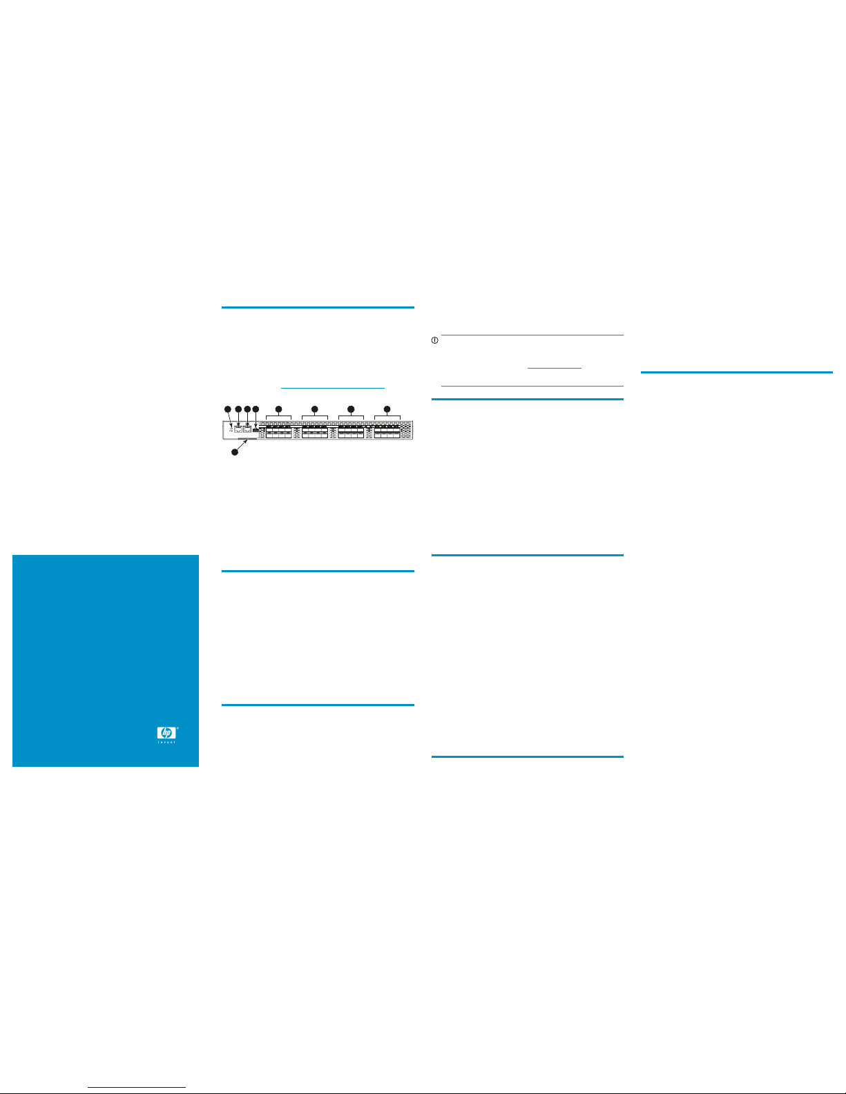
Figure 1 shows the port side of the FCoE Converged Network Switch.
3
6 7 8 9
5
1
2 4
26537a
6. 10-GbE ports 0–71. Switch ID pullout tab
7. 10-GbE ports 8–15
2. System status LED (top)
System power LED (bottom)
8. 10-GbE ports 16–233. Serial console port
9. FC ports 0–74. Management Ethernet port
5. USB port
Figure 1 Port side of the FCoE Converged Network Switch
Verify the carton contents
Verify that the carton contains the following:
• One FCoE Converged Network Switch with two power supplies and
three fan assemblies
• One accessory kit with the following items:
• Serial cable with an RJ-45 connector
• Six-foot power cords
• Rubber feet, required to set up the switch as a standalone unit
• Rack mount kit
• HP StorageWorks product documentation, including HP Storage-
Works SAN Rack Mount installation instructions, Read Me First,
Safety Guides, User License, and Warranty
Verify the installation requirements
To set up the FCoE Converged Network Switch for the first time, you will
need the following:
• Workstation with an installed terminal emulator (such as HyperTermin-
al)
• Unused IP address and corresponding subnet mask and gateway
address
• Serial cable (supplied with the switch)
• Ethernet cable
• Access to an FTP server for backing up the switch configuration (op-
tional)
• SFP+ optics and cables, or copper cables
IMPORTANT:
Order SFP+ optics or cables separately. The FCoE Converged
Network Switch only supports SFP+ optics and cables labeled
’B-s eries," SFP+, or cable. Check h
ttp://www.hp.com for more
information on supported transceivers.
Planning the site environment
To ensure adequate cooling, install the switch with the non-port side
(which contains the air intake vents) facing the cool-air aisle. Verify that
the ambient air temperature does not exceed 40°C (104°F) and that the
ambient humidity remains between 20% and 85% while the switch is
operating.
To install and operate the switch successfully, ensure that:
• The primary AC input is 100–240 VAC, 5.0 A - 2.5 A (the switch
autosenses input voltage), 47–63 Hz.
• The primary outlet is wired correctly, protected by a circuit breaker,
and grounded in accordance with local electrical codes.
• The supply circuit, line fusing, and wire size are adequate, as spe-
cified by the electrical rating on the switch nameplate.
For specific power supply information, see the HP StorageWorks 8Gb
SAN Switch hardware reference guide.
Choosing the rack mount
HP strongly recommends installing the switch in one of the following
optional HP custom racks:
• HP StorageWorks System/e Rack
• HP StorageWorks 9000 Series Rack
• HP StorageWorks 10000 Series Rack
• HP StorageWorks 10000 G2 Series Rack
Follow these guidelines:
• Use one rack unit (1U) in a 48.3 cm (19 in) cabinet.
• Ground all equipment in the rack through a reliable branch circuit
connection, and maintain ground at all times. Do not rely on a secondary connection to a branch circuit, such as a power strip.
• Ensure that airflow and temperature requirements are being met, es-
pecially if the switch is installed in a closed or multi-rack assembly.
• Ensure that the additional weight of the switch does not exceed the
rack’s weight limits or unbalance the rack.
• Secure the rack to ensure stability in case of unexpected movement.
For additional installation, electrical, environmental, and other considerations, see the HP StorageWorks 8Gb SAN Switch hardware
reference guide.
Install a standalone switch
1. Unpack the switch and verify the contents as described in Verify the
carton contents.
2. Apply the adhesive rubber feet to prevent the switch from sliding off
the supporting surface.
a. Clean the indentations at each corner on the bottom of the
switch to ensure that they are free of dust or other debris.
b. With the adhesive side against the chassis, place one rubber
foot in each indentation and press into place.
3. Place the switch on a flat, sturdy surface.
Set up a single-switch configuration
To set up a single-switch configuration, you will need the following:
• Standard screwdriver
• Fixed IP address (IPv4 or IPv6) for the switch (no DHCP server)
• Subnet mask value
• Default gateway value
• World Wide Name (WWN), located on the switch ID pullout tab
• Ethernet connection (hub or switch)
• Host computer with a Converged Network Adapter (CNA) installed
for connection to the 10-GbE CEE ports, and a Fibre Channel Host
Bus Adapter (HBA) installed for connection to the 8-Gb Fibre Channel
ports if applicable to your installation
• Ethernet and Fibre Channel cables
• Disk array with Fibre Channel ports
• Browser that allows pop-up windows
Power on the switch
1. Connect the power cords to both power supplies and then to power
sources on separate circuits to protect against AC failure.
2. Power on the power supplies by flipping both AC switches to the
position marked one (1).
The power supply LEDs are amber until power-on self-test (POST) is
complete, and then change to green.
3. After POST is complete, verify that the switch power and status LEDs
on the port side of the switch are green.
Connect the serial cable
1. Connect the serial cable to the serial port on the switch and to an
RS-232 serial port on the workstation.
If the serial port is RJ-45 instead of RS-232, remove the adapter on
the end of the serial cable and insert the exposed RJ-45 connector
into the RJ-45 serial port on the workstation.
2. Disable any serial communication programs running on the
workstation.
Page 2

3. Open a terminal emulator (such as HyperTerminal on a PC, or TERM,
TIP, or Kermit in a UNIX environment), and configure the application
as follows:
For most Windows systems:
Bits per second: 9,600
Data bits: 8
Parity: None
Stop bits: 1
Flow control: None
For most UNIX systems:
tip /dev/ttyb -9600
If ttyb is already in use, try ttya instead:
tip /dev/ttya -9600
Log in to the serial console port
1. Verify that the switch has completed POST.
When POST is complete, the port status and switch power and status
LEDs return to a normal state.
2. When the terminal emulator stops reporting information, press Enter
to display the login prompt.
3. Log in to the switch as admin, using the default password,
password.
You are prompted to change the default password at initial login.
Set a static IP address
1. Use the ipaddrset command to set the Ethernet IP address.
• For an IPv4 address, use dotted-decimal notation:
Ethernet IP Address: 192.168.74.102
• For an IPv6 address, use colon-separated notation:
switch:admin> ipaddrset -ipv6 --add
1080::8:800:200C:417A/64
The following message confirms the change:
IP address is being changed...Done.
2. Provide the rest of the network information.
Ethernet Subnetmask: 255.255.255.0
Ethernet IP Address: 192.168.74.102
Ethernet Subnetmask: 255.255.255.0
3. Optionally, verify the IP address by entering the ipAddrShow
command at the prompt.
4. Record the IP address on the pullout tab on the port side of the switch.
5. If the serial port is no longer required, use the logout command
to log out of the serial console. Remove the serial cable and replace
the plug in the serial port.
6. Connect the Ethernet port on the switch to the Ethernet network that
has just assigned the IP address.
NOTE:
DHCP is supported. See the
Brocade Converged Enhanced
Ethernet Administrator’s Guide
to set up DHCP with the
FCoE Converged Network Switch.
Set the date and time
The date and time settings are used for logging, error detection, and
troubleshooting.
1. Using a telnet or an ssh session, connect to the switch using the
IP address just configured and log in to the switch as admin, using
the default password, password.
2. Enter the date command using the following syntax:
date "mmddHHMMyy"
• mm is the month; valid values are 01 through 12.
• dd is the date; valid values are 01 through 31.
• HH is the hour; valid values are 00 through 23.
• MM is minutes; valid values are 00 through 59.
• yy is the year; valid values are 00 through 99.
3. Enter the tsTimeZone command:
switch:admin> tstimezone [--interactive]/
[, timezone_fmt]
Use timezone_fmt to set the time zone by country/city or by
time-zone ID, such as PST. The following example shows how to
change the time zone to US/Central.
switch:admin> tstimezone
Time Zone : US/Pacific
switch:admin> tstimezone US/Central
switch:admin> tstimezone
Time Zone : US/Central
4. Enter the tsClockServer command to synchronize local time:
switch:admin> tsclockserver “<ntp1;ntp2>”
The value of ntp1 is the IP address or DNS name of the first NTP
server, which the switch must be able to access. The value of ntp2
is the second NTP server and is optional. When multiple NTP server
addresses are specified, tsclockserver sets the first obtainable
address as the active NTP server. The default value is LOCL.
switch:admin> tsclockserver
LOCL
switch:admin> tsclockserver "132.163.135.131"
switch:admin> tsclockserver
132.163.135.131
switch:admin>
Verify operation and backup configuration
1. Check the LEDs to verify that all components are functional. For
information about LED patterns, see the HP StorageWorks 8Gb SAN
Switch hardware reference guide.
2. Verify that the switch prompt is displayed on the workstation
connected to the switch.
3. Verify correct operation of the switch by issuing the switchShow
command.
4. Back up the switch configuration to an FTP server, by issuing the
configUpload command and following the prompts.
Connect the devices
1. If necessary, remove the plugs on the switch from the ports to be
used.
2. Ensure that the bail (wire handle) is in the unlocked position, and
then place the SFP+ optic in the correct position on the port. (See
Figure 2.)
3. Slide the SFP+ optic or copper cable into the port until it clicks into
place, and then close the bail.
Figure 2 Installing the FC (8Gb SFP+) and CEE (10Gb SFP+) ports
NOTE:
On the bottom of each SFP+ optic is a 10-pad
gold-plated PCB-edge connector. To insert an SFP+ optic
into the upper row of ports, the gold edge must be
down. To insert an SFP+ optic into the lower row of
ports, the gold edge must be up.
4. Check the LEDs to verify that all components are functional.
5. Verify correct operation of the switch by entering the switchShow
command from the workstation.
Configuring CEE ports for CNA connectivity
Perform the following configuration steps on the CEE ports to establish
CNA connectivity and an FCoE Converged Network Switch login. CEE
port 0/0 is displayed as an example and all user input responses are
displayed in bold.
1. Configure LLDP for the FCoE Converged Network Switch that is
common to all CEE ports.
switch:admin> cmsh
switch# enable
switch# config terminal
switch(config)# protocol lldp
switch(conf-lldp)# advertise dcbx-fcoe-app-tlv
switch(conf-lldp)# advertise dcbx-fcoe-logical-link-tlv
switch(conf-lldp)# exit
2. Create a CEE Map to carry LAN and SAN traffic common to all CEE
ports.
switch(config)# cee-map default
switch(conf-ceemap)# priority-group-table 1 weight 40 pfc
switch(conf-ceemap)# priority-group-table 2 weight 60
switch(conf-ceemap)# priority-table 2 2 2 1 2 2 2 2
switch(conf-ceemap)# exit
3. Create an FCoE Converged Network Switch VLAN and add an in-
terface, as follows:
switch(config)# vlan classifier rule 1 proto fcoe encap ethv2
switch(config)# vlan classifier group 1 add rule 1
switch(config)# interface vlan 5
NOTE:
The VLAN number can be any number except the number
one (1).
switch(conf-if-vl-5)# fcf forward
switch(conf-if-vl-5)# exit
4. Configure interfaces for each port as displayed in the following ex-
ample:
switch(config)#interface tengigabitethernet 0/0
switch(conf-if-te-0/0)# switchport
switch(conf-if-te-0/0)# switchport mode access
switch(config-if-te-0/0)# vlan classifier activate group 1 vlan 5
switch(conf-if-te-0/0)# qos flowcontrol pfc 3 tx on rx on
switch(config-if-te-0/0)# cee default
switch(config-if-te-0/0)# shutdown
switch(config-if-te-0/0)# no shutdown
switch(config-if-te-0/0)# exit
Repeat step 4 for all interfaces being configured.
5. Save the running config to flash memory as displayed in the following
output:
switch:admin> exit
switch#copy running-config startup-config
Overwrite the startup config file (y/n): y
Building configuration...
switch# exit
6. Verify that the CEE port link status and the VLAN status is correct as
displayed in the following output:
switch:admin> cmsh
switch# show ip interface brief
Interface IP-Address Status
========= ========== ======
TenGigabitEthernet 0/0 unassigned up
switch#show vlan brief
VLAN Name State Ports
(u)-Untagged, (t)-Tagged
======= ================ ======= ========================
=
1 default ACTIVE Te 0/0(u)…
5 VLAN0005 ACTIVE Te 0/0(u)…
switch# exit
switch:admin>
 Loading...