

Page 1
HOT GAS REHEAT OPTION
Are uncontrollable humidity problems
costing you a bundle?
Why put up with humidity problems
when you can have true climate control
with the installation of an FHP water
source heat pump with the Hot Gas
Reheat Option (Humidimiser option).
When your FHP unit contains this
Underwriters Laboratory (UL) approved
optional feature...your normal air conditioning
cycle converts, as required, to an air drying operation.
Your FHP unit with the Humidimiser option will
provide cooling, heating, and dehumidication by
setting our combination thermostat/humidistat control.**
This option is available on the full range of FHP products.
This option is ideal for any application where a high level
of dehumidication is required. Typical applications are:
Indoor Pool Areas*
Outside/Make-Up Air Applications**
Computer Rooms
Hotel rooms during non-occupancy
* Note: Special coil and/or cabinet coating may be necessary
** Note: Cooling always takes priority over dehumidication.
FHP MANUFACTURING COMPANY
601 N.W. 65TH COURT • FT. L AUDERDALE, FL 33309 • PHONE: (954) 776-5471 • FAX: (800) 776-5529
http://www.fhp-mfg.com
ISO 9001: 2000 Certified
heat pumps
970-196 Rev. 10/04
Page 2
HEAT RECOVERY PACKAGE
Table of Contents
Model Nomenclature ....................................................................................................1
Inspection..........................................................................................................................2
Application........................................................................................................................2
Field Mounting HR .........................................................................................................2
Water Tank Preparation ................................................................................................3
HR Water Piping...............................................................................................................3
Typical Installation..........................................................................................................3
Water Tank Refill..............................................................................................................4
Installation Start-Up.......................................................................................................4
Trouble Shooting ............................................................................................................4
Electrical Diagram...........................................................................................................4
Capacity Data...................................................................................................................4
MOD EL NOM ENCL ATUR E
HR OO1 -1
HEAT RECOVERY
PACKAGE
HEAT EXCHANGER
DESIGNATOR
208/230-1-60
Page 3
2
HEAT RECOVERY
FORWARD:
The complete instruction manual should be read carefully
before beginning installation. Follow the instructions
precisely to insure proper operation of the system.
The instructions are to be left with the homeowner for
future reference if needed. All local, state and national
codes supercede these instructions and must be strictly
adhered to.
UNCRATING A ND INSPEC TION:
Check for shipping damage, both visible and concealed if
there exists any indication of damage immediately file a
claim with the shipping company. You are the only one to
file a claim regardless of why the damage was incurred or
by whom. Remove the access cover and check all of the
components parts to make sure they are properly secured
before installing the unit. Parts broken loose from their
secured position with resultant damage is considered
damage during shipment.
APPLI CATI ON:
The Heat Recovery unit is a forced pumped unit that
employs a circulating pump to move water through a
double wall/vented heat exchanger and returns the heated
water to the water tank. The water is heated by
superheated refrigerant discharge gas from the
compressor. This waste heat of the cooling mode captured
by the heat recovery increases the capacity and efficiency
of the heat pump unit. If the air temperature is
uncomfortable coming from the air vents in the heating
mode the heat recovery may need to be turned off. In the
heating mode the heat recovery captures heat that would
normally be used for space heating.
based on reduced loads thus the ability to heat hot water is
also reduced. This same result could be noticeable on units
that are over sized for the served loads thus resulting in
short cycling of the heat pump and HRP package.
The HRP is equipped with a LGL (low discharge gas limit)
that disables the HRP pump from operating until discharge
gas temperatures are above the required levels to insure
proper operation. This eliminates the possibility of actually
absorbing heat from the water in the hot water tank. This
safety feature could also reduce HRP run time and further
diminish HRP performance.
FIELD MOUNT ING EM/EC S ERIES HR KI T:
It is recommended that the heat recover y package be
factory mounted at the time the heat pump is purchased.
This eliminates field intrusion into the refrigeration circuit
of the heat pump and the associated problems that may
arise. If the heat recover y package is to be field installed the
following steps must occur:
1. Disconnect all power supplies to the unit before
servicing. More than one power supply may be present.
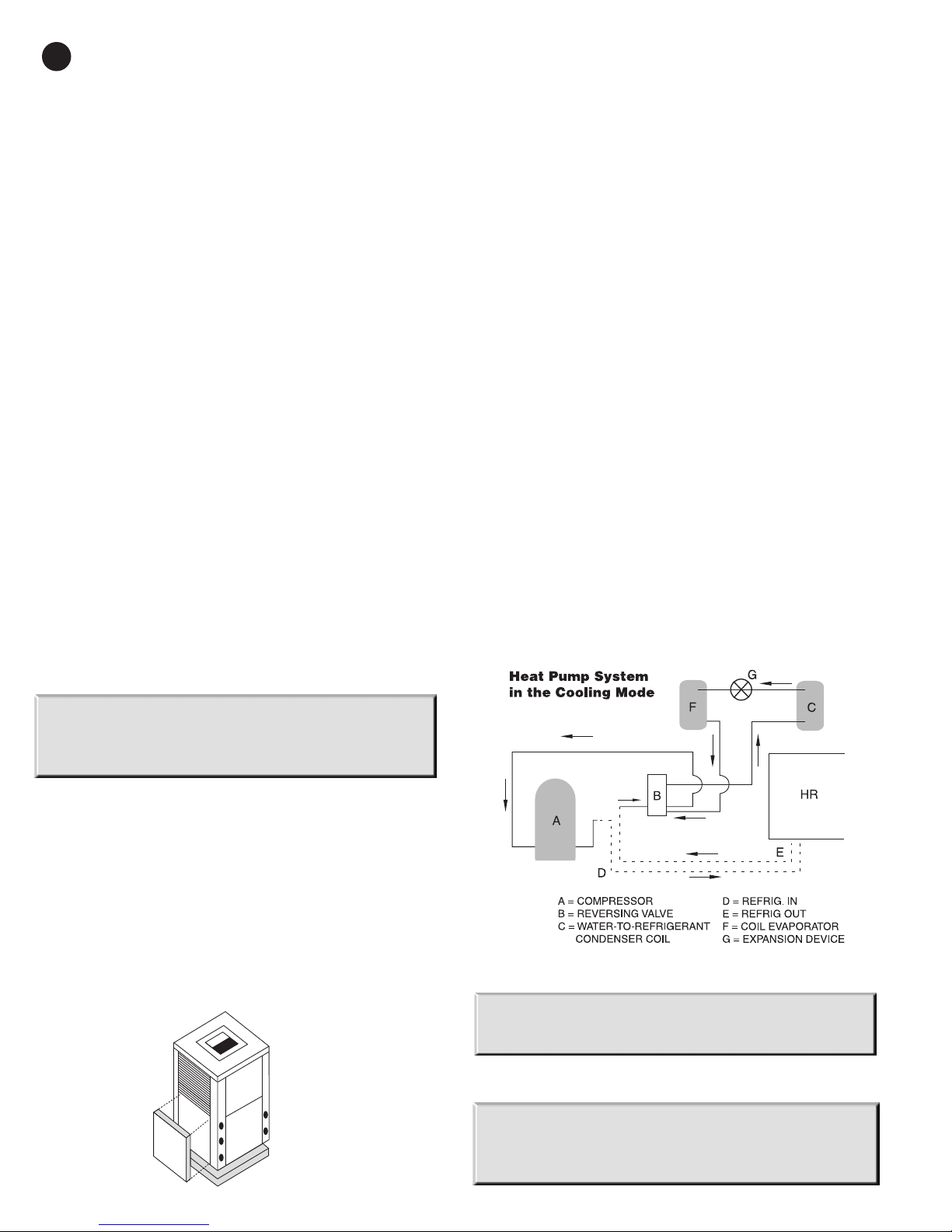
2. Remove the lower left side heat pump access panel.
This is where the heat recovery kit will be attached.
(Figure #1)
3. Mark and drill holes in panel where heat recovery
package hot gas in and out lines will enter and exit.
Allow enough space for lines not to touch panels.
4. Mount heat recovery package to panel using sheet
metal screws.
NOTE: The performance of the heat recovery package is
based on a variety of variables and may vary from unit to
unit and from application to application based on the
operating conditions of the complete system.
When the HRP is applied to highly efficient heat pumps,
especially the newly released high efficiency 2-step scroll
R410A units, the capacity of the HRP will be reduced due to
lower condensing temperatures and resulting lower
discharge gas temperatures and available super heat levels
for hot water heating. Reduced HRP capacity will also be
evident when the heat pump is applied to low water
temperature systems such as low temperature open wells
and when ground loops are changing over in the spring
months from the heating to the cooling mode.
HRP capacity is also a function of heat pump run times. In
the milder months the heat pump run time will be reduced
(Figure #1)
(Figure #2)
CAU TION: Do not mount heat recovery unit to panel while
on unit. Refrigerant containing components are present
and may be damaged.
5. Remove refrigerant from heat pump utilizing standard
refrigerant recovery techniques.
WARNING: Recovery of this substance is mandatory and
State/ Federally regulated. Failure to recover this
refrigerant properly can/will result in serious penalties
including substantial fines and/or prison sentences.
Page 4
HEAT RECOVERY
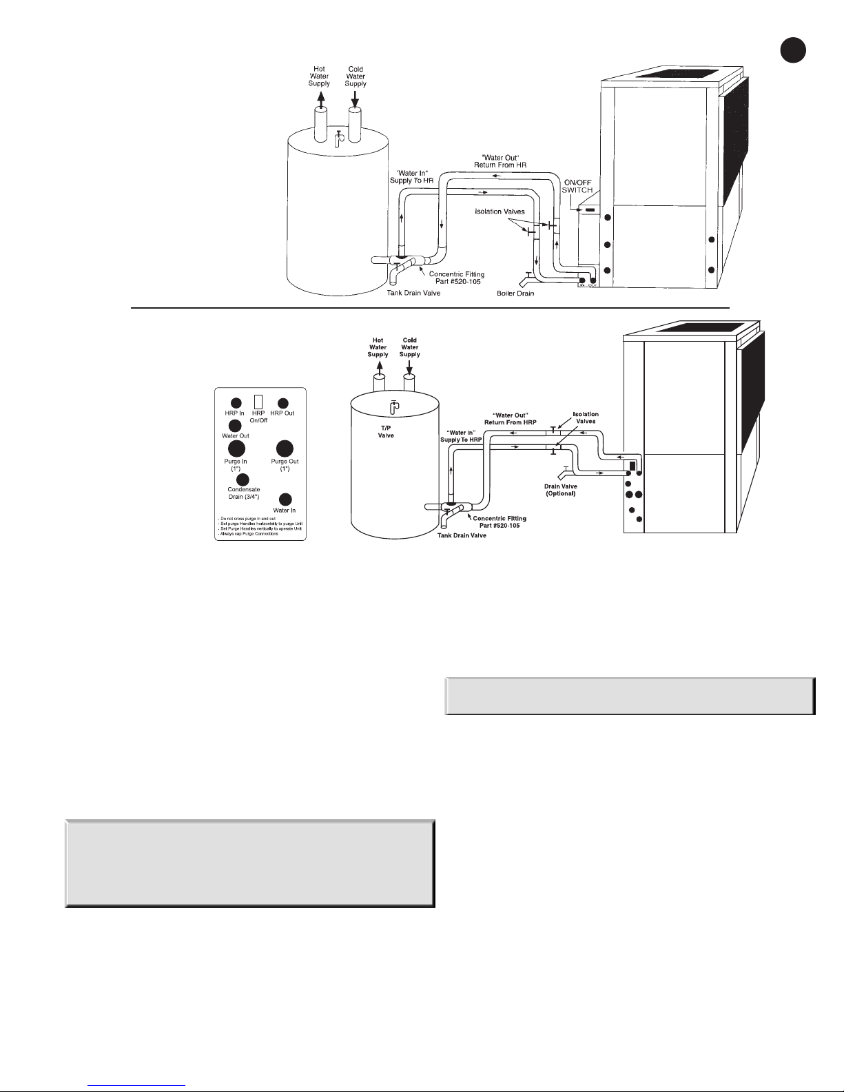
TYPICAL CONNECTION
DIAGRAM FOR
EM/EC SERIES
TYPICAL CONNECTION
DIAGRAM FOR EV/ES, AU, AP,
GT/GS SERIES WITH
INTERNAL HRP
3
(Figure #3)
6. Cut the hot gas discharge line between the compressor
discharge port and the reversing valve inlet. Connect the
discharge line from the compressor to the line marked
“Refrigerant in” on the heat recovery coil. Connect the
line marked “Refrigerant out” of the heat recovery coil to
the reversing valve inlet line. (Figure #2)
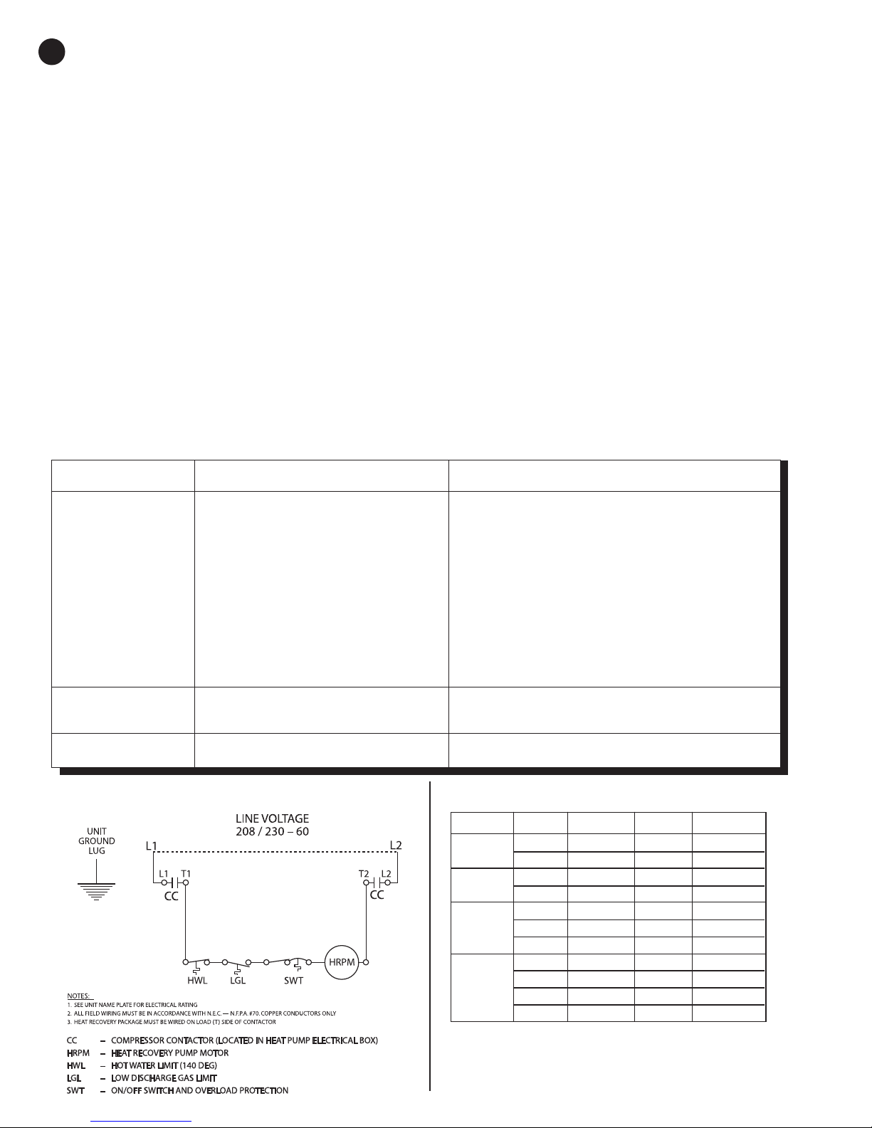
7. Make the wiring connections from the heat recovery
package to the compressor contactor as shown.
(Figure #4)
8. It is imperative that the refrigerant system remain clean
and dry during the above operations. If there is doubt of
this a bi-flow liquid line dryer must be installed.
9. Evacuate the unit and recharge according to unit
nameplate.
WARNING: If heat recovery unit is installed in an area where
freezing may occur the unit must be drained during winter
months to prevent heat exchanger damage. Heat exchanger
ruptures that occur due to freezing will void the heat recovery
package warranty along with the heat pump warranty.
WATER TANK PREPARATION:
1. Turn off electrical or fuel supply to the water heater.
2. Attach garden hose to water tank drain connection and
run other end of hose out doors or to an open drain.
3. Close cold water inlet valve to water heater tank.
4. Drain tank by opening drain valve on the bottom of the
tank, then open pressure relief valve or hot water faucet.
5. Once drained the tank should be flushed with cold water
until the water leaving the drain hose is clear and free of
sediment.
6. Close all valves and remove the drain hose.
7. Install HR water piping.
NOTE: Use of Heat Recovery Packages with Smart Hot Water
Tanks is not recommended.
Application of a Heat Recovery Package with a “Smart” electric
hot water tank may cause nuisance fault errors in the tank’s
on-board diagnostics. In operation, a Heat Recovery Package
can raise the water temperature in the hot water tank, even if
the tank’s on-board system is not calling for heat from the
tank’s internal heater elements. This rise in tank water
temperature while the tank is idle may be interpreted as a
heater element that is stuck “on” by a smart tank’s diagnostic
system.
If this occurs, the Heat Recovery Package may need to be
turned off at the heat pump.
HR WATER PIPI NG:
All hot water piping should be a minimum of 3/8" O.D. copper
tube to a maximum distance of fifteen (15) feet. For distances
beyond fifteen feet but not exceeding sixty (60) feet use 1/2"
copper tube. Separately insulate all exposed surface of both
connecting water lines with 3/8" wall closed cell insulation.
Install isolation valves on supply and return to the heat
recovery. (Figure #3)
Page 5
4
HEAT RECOVERY
WATER TANK REFILL:
1. Open the cold water supply to the tank.
2. Open a hot water faucet to vent air from the system until
water flows from the faucet, then close.
3. Depress the hot water tank pressure relief valve handle to
ensure there is no air remaining in the tank.
4. Carefully inspect all plumbing for water leaks . Correct as
required.
5. Purge all air from HR by depressing the schrader valve on
the HR Unit. Allow all air to bleed out until water appears
at the valve.
6. Before restoring the power or fuel supply to the water
heater, adjust the temperature setting on the tank
thermostat(s) to ensure maximum utilization of the heat
available from the refrigeration system and conserve the
most energy. On tanks with both upper and lower
elements and thermostats, the lower element should be
turned down to 100° F, while the upper element should
be adjusted to 140° F. Depending upon the specific needs
of the customer, you may need to adjust the upper
TROUBLE SHOOTING
PROBLEM
POSSIBLE CAUSE
element differently. On tanks with a single thermostat
lower the thermostat setting to 140° F or the “LOW”
position.
7. After thermostat adjustments are completed, replace
access cover and restore electrical or fuel supply to water
heater.
INITI AL S TART-U P:
1. Make sure all valves in heat recovery water piping
system are open. NEVER OPERATE HR PUMP DRY.
2. Turn on the heat pump. The HR pump should not run if
the compressor is not running.
3. Turn HR switch to the “ON” position. The pump will
operate if entering water temperature to HR is below
140° F.
4. The temperature difference between the water entering
and leaving the heat recovery should be 5° to 15° F.
5. Allow the unit to operate for 20 to 30 minutes to ensure it
is functioning properly. The pump should shut off when
the water temperature entering the heat recovery
reaches 140°F.
CHECKS AND CORRECTIONS
No Flow
Low Flow
No Power
On/Off Switch Position
Compressor Contactor
Broken or loose wires
Air Lock
Stuck pump shaft/impeller
Defective pump
Kinked or under sized water piping
High Water
Temperature
Low Heat Output
Water temp limit closed
Scaled or fouled heat exchanger
LINE VOLTAGE CONTROL DIAGRAM
(Figure #4)
Check power supply
Set switch to “ON” position
Engage heat pump contactor
Repair or tighten wires
Purge air from piping system
Remove pump cartridge and clean
Replace pump
Repair kink and check for proper line size
Stuck limit switch
Sensor not attached securely to line
Clean heat exchanger
CAPACITY DATA
MODEL
HR000
HR001
HR002
HR003
* Capacity based on entering domestic water temperature of 80° F,
entering superheated discharge gas temperature 180° F, and leaving
saturated vapor temperature 105° F. R-22 refrigerant shown.
Use: .950 multiplier for R410A. (See page 2 - Application)
NOMINAL HR CAPACITY GHR GPM
UNIT TONS (BTU/HR.) FLOW RATE
1.0 1,430 .50 .4
1.5 2,140 .75 .7
1.0 2,858 .50 .8
1.5 4,287 .75 1.3
2.0 5,716 1.00 1.7
2.5 7,146 1.25 2.1
3.0 8,575 1.50 2.5
3.5 10,004 1.75 2.9
4.0 11,433 2.00 3.4
4.5 12,862 2.25 3.8
5.0 14,292 2.50 4.2
POTENTIAL
SAVINGS PER HOUR
EQUIV. - Kwh
970-299 Rev. 3/08
 Loading...