

Page 1
AP SERIES
AP SERIES
Table of Contents
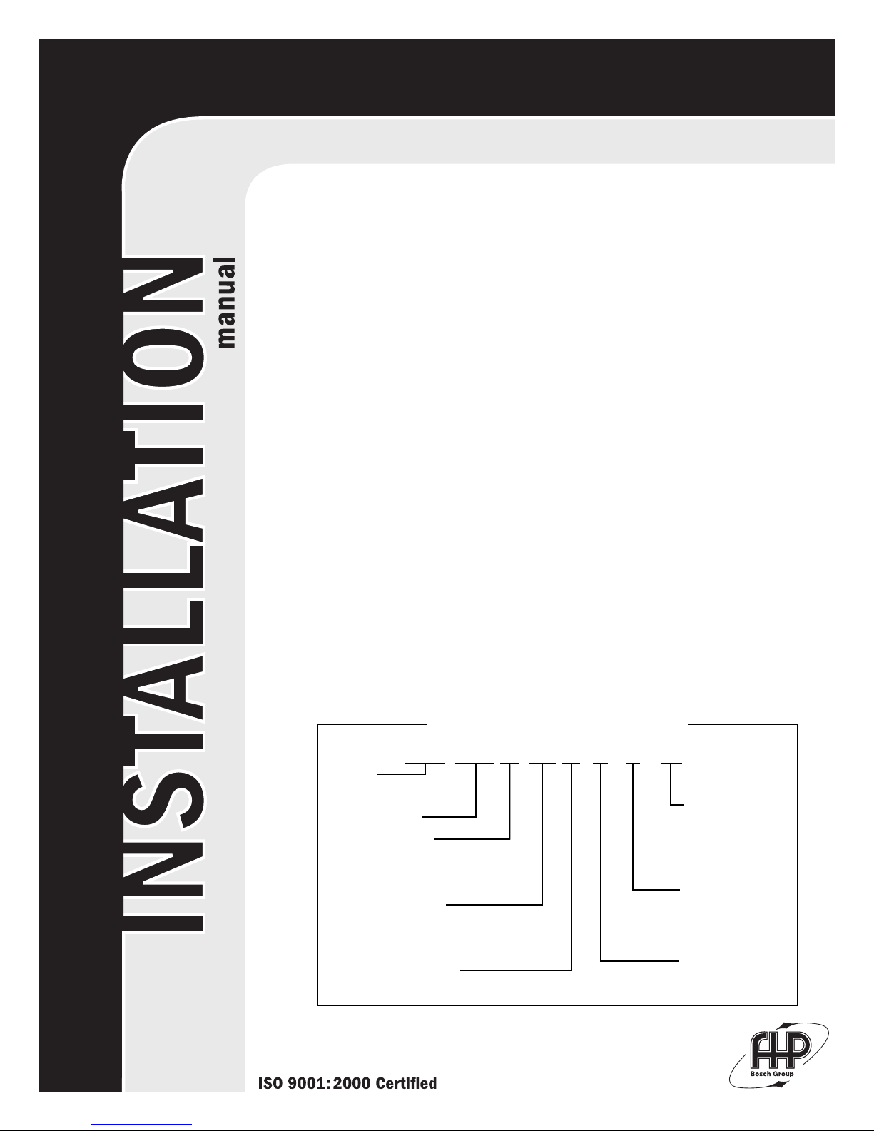
Model Nomenclature ..................................................................................................................1
Initial Inspection............................................................................................................................2
General Description .....................................................................................................................2
Moving and Storage ....................................................................................................................2
Safety Considerations .................................................................................................................2
Location............................................................................................................................................2
Installation.......................................................................................................................................2
Condensate Drain.........................................................................................................................3
Duct System....................................................................................................................................3
Piping ................................................................................................................................................3
Electrical...........................................................................................................................................4
Thermostat Connections ...........................................................................................................4
Safety Devices & the UPM Controller....................................................................................5
Electric Heater Package Option...............................................................................................6
Sequence of Operation Single Stage Units.........................................................................7
Sequence of Operation Two-Stage Units............................................................................7
Well Water Systems .....................................................................................................................7
Installation of Pressure Regulating Valves..........................................................................7
Cooling Tower / Boiler Application........................................................................................7
Earth Coupled Systems...............................................................................................................8
System Checkout ..........................................................................................................................8
Unit Start-Up...................................................................................................................................8
Maintenance...................................................................................................................................8
Wiring Diagrams ...........................................................................................................................9
Trouble Shooting .......................................................................................................................13
Unit Check Out............................................................................................................................14
Operating Pressures & Temperatures.................................................................................15
970-292 Revised 5-12
AP 049 -1 VT C-F L T
SERIES:
AP-AQUARIUS II
NOMINAL CAPACITY:
VOLTAGE DESIGNATION:
1 - 208/1/60 & 230/1/60
CABINET CONFIGURATION:
VT - VERTICAL
HZ - HORIZONTAL
CF - COUNTERFLOW
HEAT EXCHANGER MATERIAL:
C - COPPER
N - CUPRO-NICKEL
MODEL NOMENCLATURE
SUPPLY AIR LOCATION:
T - TOP (VT ONLY)
E - END BLOW (HZ ONLY)
B - BOTTOM (CF ONLY)
RETURN AIR LOCATION:
L - LEFT
R - RIGHT
B - BACK
F - FRONT
WATER CONNECTION
LOCATION:
F - FRONT
Page 2
2
AP SERIES
INITIAL INSPECTION:
Be certain to inspect all cartons or crates on each unit as
received at the job site before signing the freight bill. Verify
that all items have been received and that there are no
visible damages; note any shortages or damages on all
copies of the freight bill. In the event of damage or
shortage, remember that the purchaser is responsible for
filing the necessary claims with the carrier. Concealed
damages not discovered until after removing the units from
the packaging must be reported to the carrier within 24
hours of receipt.
GENERAL DESCRIPTION:
These Water-to-Air Heat Pumps provide the best
combination of performance and efficiency available.
Safety devices are built into each unit to provide the
maximum system protection possible when properly
installed and maintained.
The AP Water-to-Air Heat Pumps are Underwriters
Laboratories (UL) and (cUL) listed for safety. The water-toAir Heat Pumps are designed to operate with entering fluid
temperature between 20°F to 80°F in the heating mode and
between 50°F to 110°F in the cooling mode.
NOTE: 50°F Min. EWT for well water applications with
sufficient water flow to prevent freezing. Antifreeze
solution is required for all closed loop applications. Cooling
Tower/Boiler and Earth Coupled (Geo Thermal) applications
should have sufficient antifreeze solution to protect against
extreme conditions and equipment failure. Frozen water
coils are not covered under warranty.
NOTE: This product should not be used for temporarily
heating/cooling during construction. Doing so may effect
the units warranty.
MOVING AND STORAGE:
If the equipment is not needed for immediate installation
upon its arrival at the job site, it should be left in its
shipping carton and stored in a clean, dry area. Units must
only be stored or moved in the normal upright position as
indicated by the "UP" arrows on each carton at all times. If
unit stacking is required, stack units as follows: Vertical
units less than 6 tons, no more than two high. Horizontal
units less than 6 tons, no more than three high. "Do not
stack units larger than 6 tons."
SAFETY CONSIDERATIONS:
Installation and servicing of this equipment can be
hazardous due to system pressure and electrical
components. Only trained and qualified personnel should
install, repair, or service the equipment. Untrained
personnel can perform basic functions of maintenance
such as cleaning coils and replacing filters.
WARNING: Before performing service or maintenance
operations on the system, turn off main power to the unit.
Electrical shock could cause personal injury or death.
When working on equipment, always observe precautions
described in the literature, tags, and labels attached to the
unit. Follow all safety codes. Wear safety glasses and work
gloves. Use a quenching cloth for brazing, and place a fire
extinguisher close to the work area.
970-292 Revised 5-12
LOCATION:
Locate the unit in an indoor area that allows easy removal
of the filter and access panels, and has enough room for
service personnel to perform maintenance or repair.
Provide sufficient room to make fluid, electrical, and duct
connection(s). If the unit is located in a confined space such
as a closet, provisions must be made for return air to freely
enter the space. On horizontal units, allow adequate room
below the unit for a condensate drain trap and do not
locate the unit above supply piping. These units are not
approved for outdoor installation; therefore, they must be
installed inside the structure being conditioned. Do not
locate in areas that are subject to freezing.
INSTALLATION:
NOTE: Remove all shipping blocks under blower housing.
Loosen compressor mounting bolts.
MOUNTING VERTICAL UNITS:
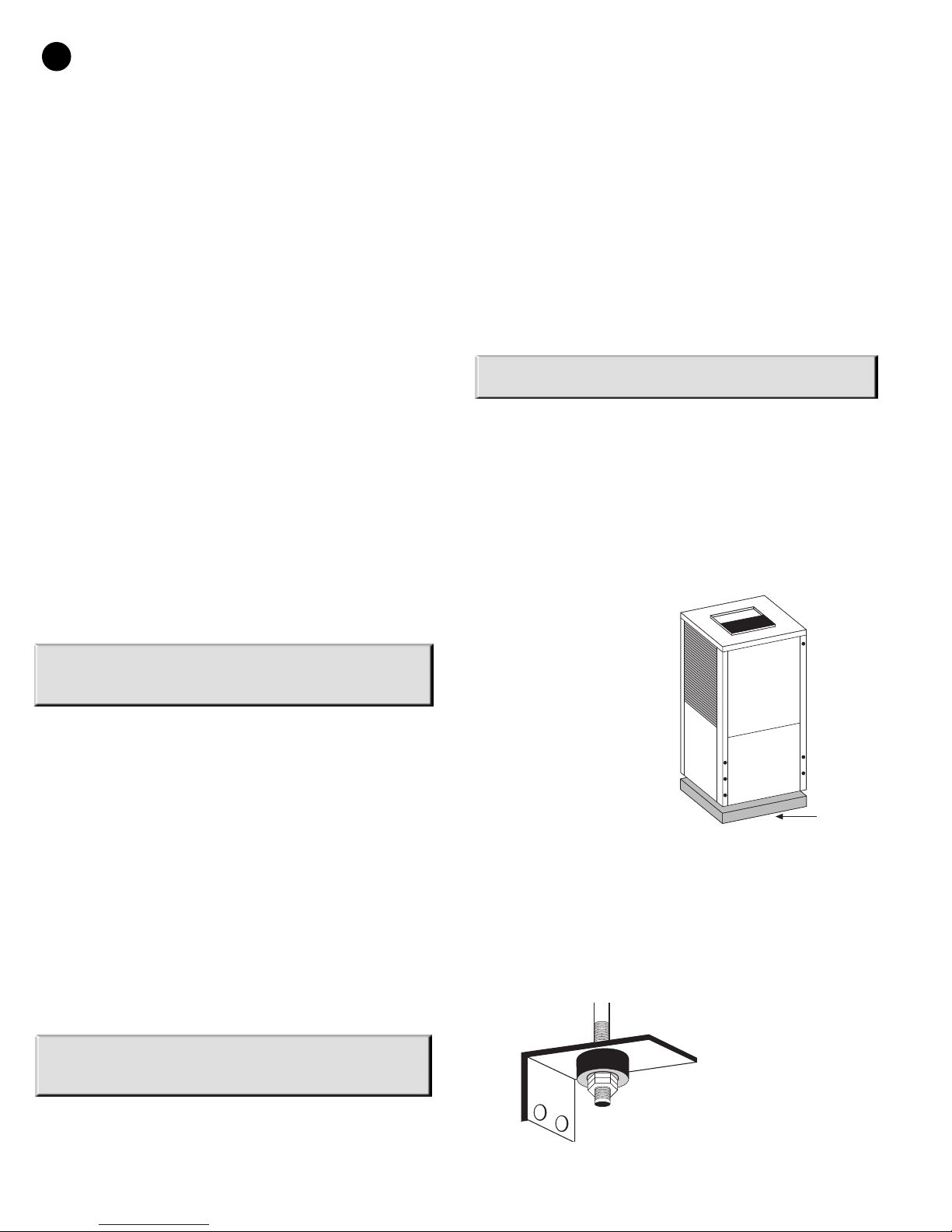
Vertical units up to six tons are available in left, right, front,
or rear air return configurations. Vertical units should be
mounted level on a vibration absorbing pad slightly larger
than the base to minimize vibration transmission to the
building structure. It is not necessary to anchor the unit to
the floor. (See Figure #1).
MOUNTING HORIZONTAL UNITS:
While horizontal units may
be installed on anylevel
surface strong enough to
hold their weight,they are
typically suspended above a
ceiling bythreaded rods.
The rods are usually
attached tothe unit corners
by hanger bracket kits (P/N
930-008).(See Figure #2).
The rods must be
securelyanchored to the
ceiling and be capable of
supporting the unit weight.
Refer to the
hangingbracket assembly
and installation instructions included with the unit fordetails.
Horizontal units installed above theceiling must conform to all
local codes. Anauxiliary drain pan if required by code should
be atleast four inches larger than the bottom of theheat
pump. Plumbing connected to the heat pumpmust not come
in direct contact with joists,trusses, walls, etc.
Some applications
require an attic floor
installation of the
horizontal unit. In this
case the unit should be
set in a full size
secondary drain pan on
(Figure #2)
secondary drain pan prevents possible condensate
overflow or water leakage damage to the ceiling. The
top of a vibration
absorbing mesh. The
(Figure #1)
VIBRATION
PAD
FULL SIZE
Page 3
AP SERIES
AP SERIES
3
secondary drain pan is usually placed on a plywood base
isolated from the ceiling joists by additional layers of
vibration absorbing mesh. In both cases, a 3/4" drain
connected to this secondary pan should be run to an eave
at a location that will be noticeable. If the unit is located in
a crawl space, the bottom of the unit must be at least 4"
above grade to prevent flooding of the electrical parts due
to heavy rains.
CONDENSATE DRAIN:
NOTE: If equipped with float style condensate overflow
switch, final adjustment must be made in the field.
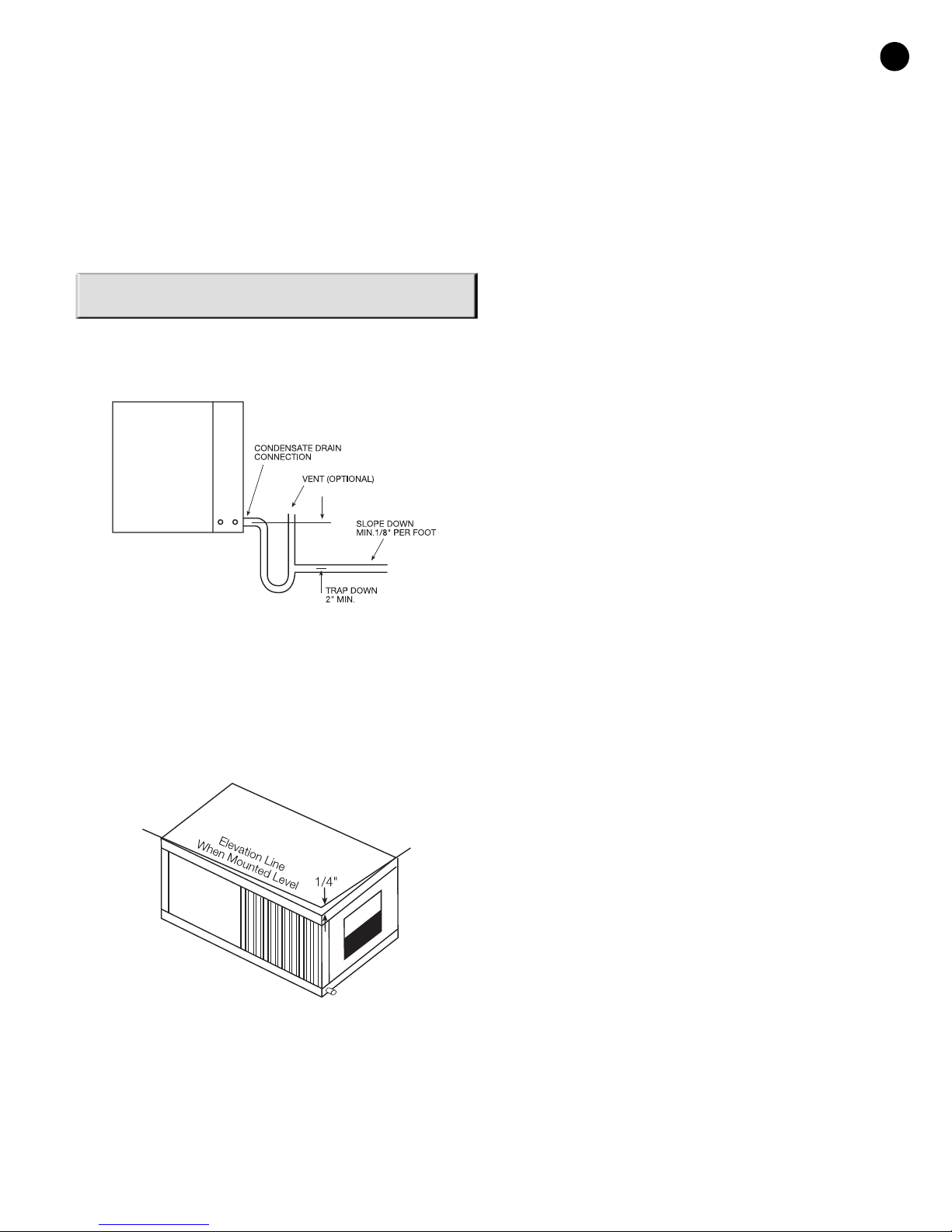
A drain line must be connected to the heat pump and
pitched away from the unit a minimum of 1/8" per foot to
allow the condensate to flow away from the unit.
(Figure #3)
This connection must be in conformance with local
plumbing codes. A trap must be installed in the condensate
line to insure free condensate flow. (Heat Pumps are not
internally trapped). A vertical air vent is sometimes
required to avoid air pockets. (See Figure #3). The length of
the trap depends on the amount of positive or negative
pressure on the drain pan. A second trap must not be
included.
A flexible connector is recommended for supply and return
ir duct connections on metal duct systems. All metal
a
ducting should be insulated with a minimum of one inch
duct insulation to avoid heat loss or gain and prevent
condensate forming during the cooling operation.
Application of the unit to uninsulated duct work is not
recommended as the unit’s performance will be adversely
affected. Do not connect discharge ducts directly to the
blower outlet. The factory provided air filter must be
removed when using a filter back return air grill.The factory
filter should be left in place on a free return system.
If the unit will be installed in a new installation which
includes new duct work, the installation should be
designed using current ASHRAE procedures for duct sizing.
If the unit is to be connected to existing ductwork, a check
should be made to assure that the duct system has the
capacity to handle the air required for the unit application.
If the duct system is too small, larger ductwork should be
installed. Check for existing leaks and repair.
The duct system and all diffusers should be sized to handle
the designed air flow quietly. To maximize sound
attenuation of the unit blower, the supply and return air
plenums should be insulated. There should be no direct
straight air path thru the return air grille into the heat
pump. The return air inlet to the heat pump must have at
least one 90 degree turn away from the space return air
grille. If air noise or excessive air flow are a problem, the
blower speed can be changed to a lower speed to reduce
air flow. (Refer to ECM motor interface board section in this
manual and Figure #7)
PIPING:
Supply and return piping must be as large as the unit
connections on the heat pump (larger on long runs). Never
use flexible hoses of a smaller inside diameter than that of
the fluid connections on the unit. AP units are supplied
with either a copper or optional cupro-nickel condenser.
Copper is adequate for ground water that is not high in
mineral content. Should your well driller express concern
regarding the quality of the well water available or should
any known hazards exist in your area, we recommend
proper testing to assure the well water quality is suitable
for use with water source equipment. In conditions
anticipating moderate scale formation or in brackish water
a cupro-nickel heat exchanger is recommended.
(Figure #4)
The horizontal unit should be pitched approximately 1/4"
towards the drain in both directions, to facilitate
condensate removal. (See Figure #4)
DUCT SYSTEM:
A supply air outlet collar and return air duct flange are
provided on all units to facilitate duct connections. Refer to
the FHP individual data specification sheet for physical
dimensions of the collar and flange.
970-292 Revised 5-12
Both the supply and discharge water lines will sweat if
subjected to low water temperature. These lines should be
insulated to prevent damage from condensation.
All manual flow valves used in the system must be ball
valves. Globe and gate valves must not be used due to high
pressure drop and poor throttling characteristics. Never
exceed the recommended water flow rates as serious
damage or erosion of the water to refrigerant heat
exchanger could occur.
Always check carefully for water leaks and repair
appropriately. Units are equipped with female pipe thread
fittings. Consult the specification sheets for sizes. Teflon
tape sealer should be used when connecting water piping
connections to the units to insure against leaks and
possible heat exchanger fouling. Do not overtighten the
Page 4
4
AP SERIES
connections. Flexible hoses should be used between the
unit and the rigid system to avoid possible vibration. Ball
valves should be installed in the supply and return lines for
unit isolation and unit water flow balancing.
ELECTRICAL:
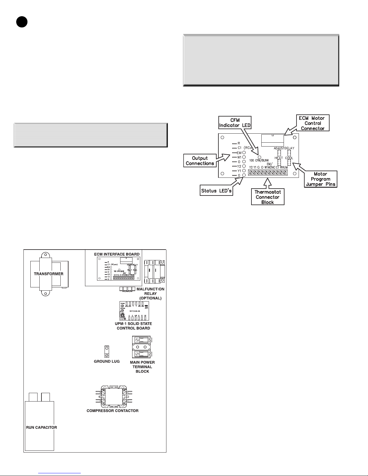
(Refer to electrical component box layout, Figure #5)
Field wiring must comply with local and national electric
codes. Power to the unit must be within the operating
voltage range indicated on the unit nameplate or on the
performance data sheet. On three phase units (single stage
units only) phases must be balanced within 2%.
CAUTION: Operation of unit on improper line voltage or
with excessive phase imbalance will be hazardous to the
unit, constitutes abuse and may void the warranty.
Properly sized fuses or HACR circuit breakers must be
installed for branch circuit protection. See unit nameplate
for maximum fuse or breaker size.
The unit is provided with a concentric knock-out in the
front left corner post for attaching common trade sizes of
conduit, route power supply wiring through this opening.
Always connect the ground lead to the grounding lug
provided in the control box and power leads to the power
supply terminal block as indicated on the wiring diagram
and Figure #5.
NOTE: U
two (2) separate power supplies: one for the unit
compressor and one for the electric heater elements,
blower motor and control circuit. Refer to the ELECTRIC
HEATER PACKAGE OPTION section and Figure #9 for wiring
instructions, minimum circuit ampacities and maximum
fuse/breaker sizing.
nits supplied with internal electric heat require
ECM INTERFACE BOARD:
(Figure #6)
(Figure #5)
Electrical Box Component Layout
THERMOSTAT CONNECTIONS:
Thermostat wiring is connected to the 10 pin screw type
terminal block on the lower center portion of the ECM
Interface Board. In addition to providing a connecting point
for thermostat wiring, the interface board also translates
thermostat inputs into control commands for the variable
speed programmable ECM DC fan motor and displays an
LED indication of operating status. The thermostat
connections and their functions are as follows:
Y2 Second Stage Compressor Operation
Y1 First Stage Compressor Operation
G Fan
O Reversing Valve (energized in cooling)
W1 Auxiliary Electric Heat
(runs in conjunction with compressor)
EM/W2 Emergency Heat (electric heat only)
NC Transformer 24 VAC Common
(extra connection)
C1 Transformer 24 VAC Common
(primary connection)
R Transformer 24 VAC Hot
HUM Dehumidification Mode
Single & Two Step
970-292 Revised 5-12
If the unit is being connected to a thermostat with a
malfunction light, this connection is made at the unit
malfunction output or relay.
Page 5
AP SERIES
5
OTE:
N
If the thermostat is provided with a malfunction light
powered off of the common (C) side of the transformer, the
unit must be provided with a malfunction relay (FHP option
# 660-006) to properly energize the light. The relay coil will
be wired across the (ALR) and (C) contacts on the unit’s UPM
board and the relay’s normally open contacts across (ALR)
and the malfunction light connection on the thermostat. If
the thermostat is provided with a malfunction light powered
off of the hot (R) side of the transformer, then the thermostat
malfunction light connection should be connected directly
to the (ALR) contact on the unit’s UPM board.
MOTOR PROFILE AIR FLOW TABLE CFM
TWO STAGE UNITS
MODEL ONLY
AP025 600 750 950 950 950 1090 800 A
AP035 900 1000 1200 1200 1200 1400 1000 A
AP049 1200 1300 1700 1700 1700 1950 1450 B
AP061 1300 1500 2000 2000 2000 2100 1900 A
AP071 1300 1500 2100 2100 2100 2300 1900 A
FAN Y1 Y2 AUX. EMERG. PLUS MINUS TAP
COOL/HEAT COOL/HEAT
HEAT HEAT ADJ ADJ
(Figure #7)
To the left of the thermostat connection block are a row of
2 red and 4 green LED’s. These LED’s indicate the operating
status of the unit. They are labeled as follows:
OTE:
N
Do not set the ADJ jumper to the (-) setting when
electric heaters are installed. Doing so may cause the
heaters to cycle on their thermal overload switches,
potentially shortening the life of the switches.
The other three sets of jumper pins are used to select the
proper program in the ECM motor for the unit. Refer to
Figure #7 for the proper jumper placement.
NOTE: Always disconnect power before changing jumper
positions on the interface board and reset the unit
afterward.
To the left of the red and green status LED’s is a row
of 1/4” male quick connects. These are used to pass
thermostat inputs on to the rest of the control circuit.
COOL/HEAT/DELAY
Remember to always turn off unit power at the circuit
breaker before attaching or disconnecting any wiring
from these connections to avoid accidental short
circuits that can damage unit control components.
SAFETY DEVICES AND THE UPM CONTROLLER
Each unit is factory provided with a Unit Protection
Module (UPM) that controls the compressor operation and
monitors the safety controls that protect the unit.
Safety controls include the following:
EM (red) Emergency Heat On
W1 (red) Auxiliary Heat On
O (green) Reversing Valve Energized, unit is
in cooling mode
Y2 (green) Second Stage Compressor On
Y1 (green) First Stage Compressor On
G (green) Fan On
Just above the connector block is a single red LED labeled
CFM that will blink intermittently when the unit is running
and may flicker when the unit is off. This LED indicates the
air delivery of the blower at any given time. Each blink of
the LED represent 100 CFM of air delivery so if the LED
blinks 12 times, pauses, blinks 12 times, etc. the blower is
delivering 1200 CFM. Refer to Figure #7 for factory
programmed air delivery settings for the ES Series.
To the right of the thermostat connection block is a green
LED labeled dehumidify.
Just above and to the right of the thermostat connection
block are four sets of jumper pins labeled ADJ, DELAY, HEAT
and COOL. The ADJ set of pins are labeled NORM, (+), (-)
and TEST. AP units will all be set on the NORM position from
the factory, however, airflow can be increased (+) or
decreased (-) by 15% from the pre-programmed setting by
relocating the jumper in this section. The TEST position is
used to verify proper motor operation. If a motor problem
is suspected, move the ADJ jumper to the TEST position and
energize G on the thermostat connection block. If the
motor ramps up to 100% power, then the motor itself is
functioning normally. Always remember to replace the
jumper to NORM, (+) or (-) after testing and reset the unit
thermostat to restore normal operation.
• High pressure switch located in the refrigerant discharge
line and wired across the HPC terminals on the UPM
• Low pressure switch located in the unit refrigerant suction
line and wired across terminals LPC1 and LPC2 on the UPM.
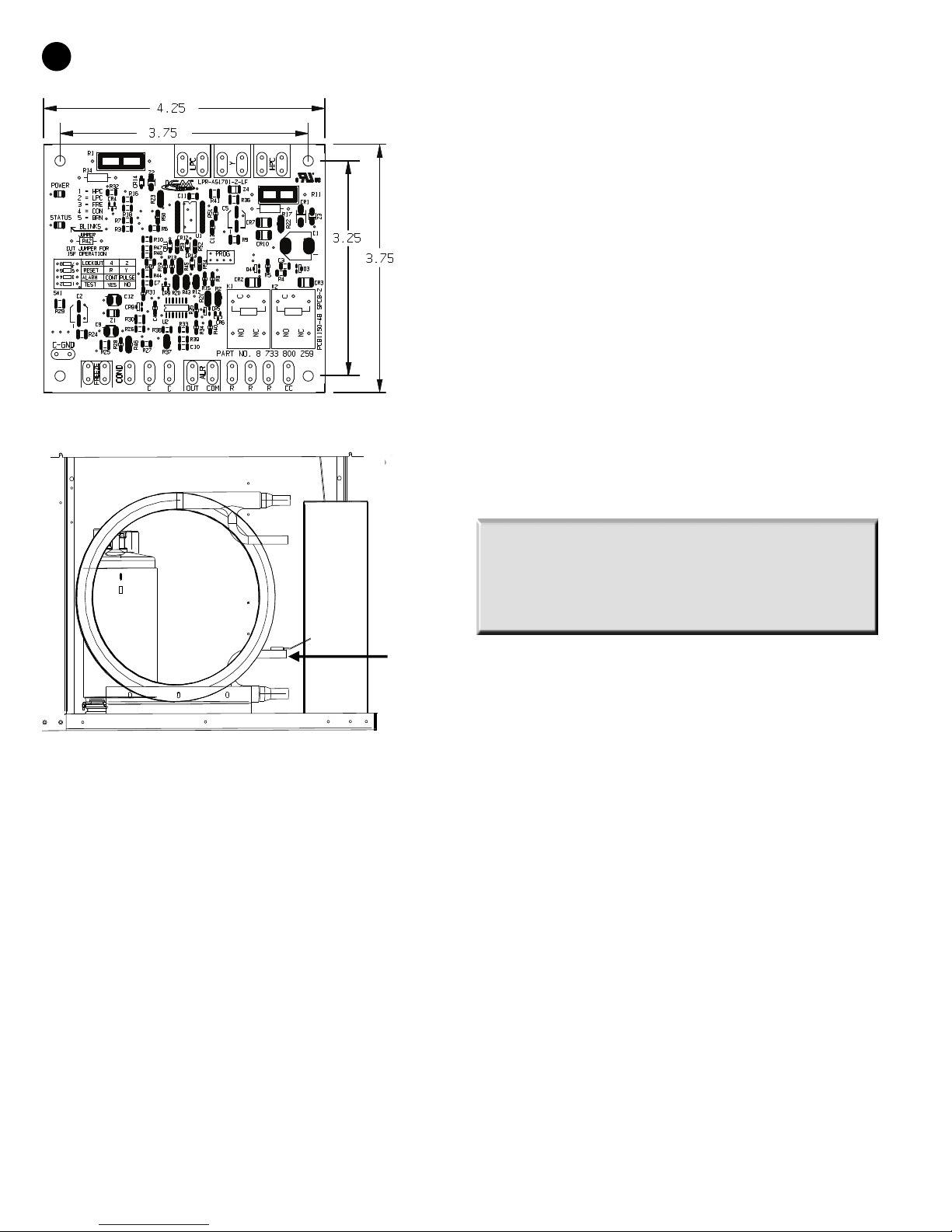
• Optional freeze protection sensor, mounted close to
condensing water coil, monitors refrigerant temperature
between condensing water coil and thermal expansion
valve. If temperature drops below or remains at freeze
limit trip for 30 seconds, the controller will shut down the
compressor and enter into a soft lockout condition. The
default freeze limit trip is 30°F, however this can be
changed to 15°F by cutting the R42 resistor located on top
of DIP switch SW1.
• The condensate overflow protection sensor is located
in the drain pan of the unit and connected to the
‘COND’ terminal on the UPM board.
NOTE: If freeze protection sensor is not installed, a jumper
between freeze contacts must be installed on the UPM
board otherwise unit will not start.
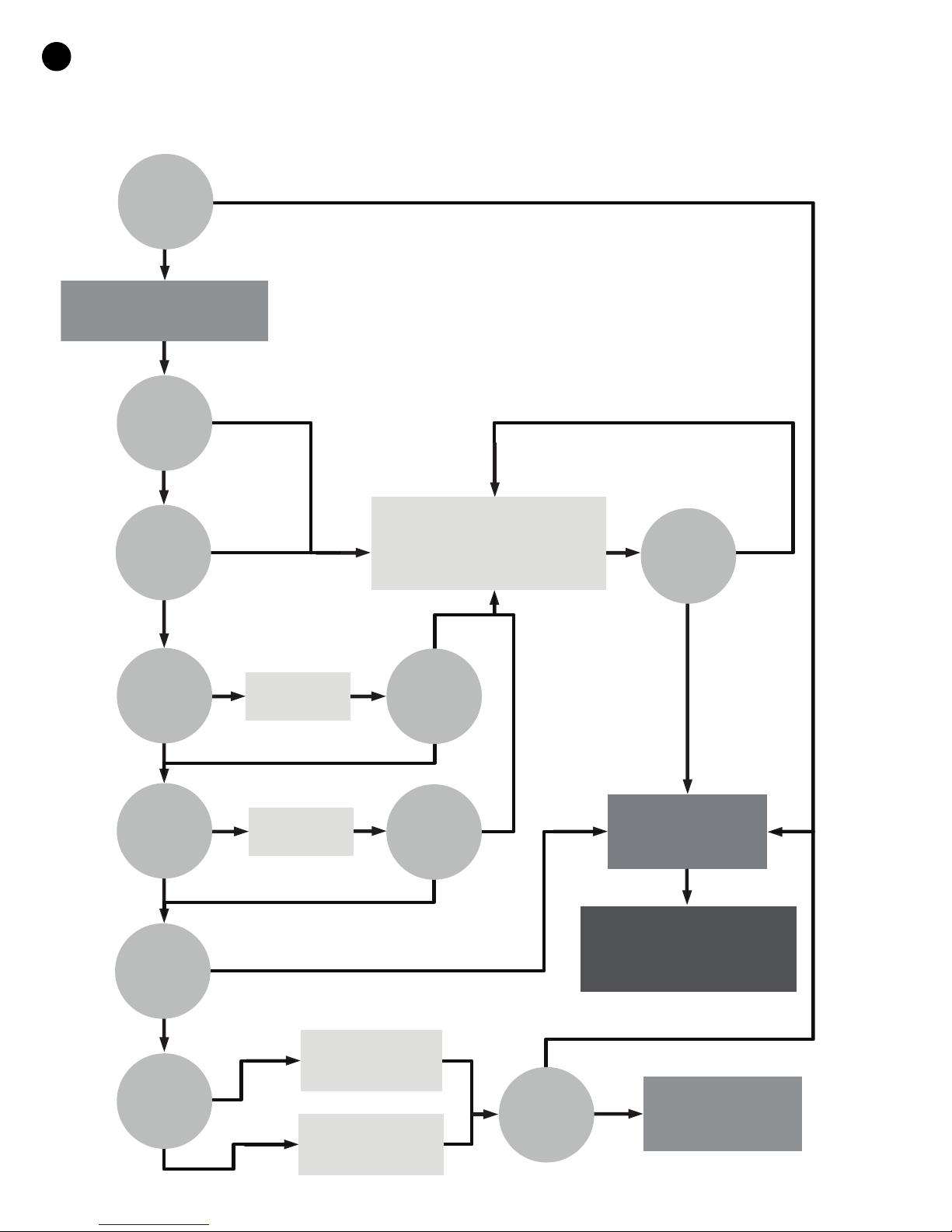
The UPM includes the following features:
• ANTI-SHORT CYCLE TIME—5 minute delay on break
timer to prevent compressor short cycling.
•
RA ND OM START—Each controller has a unique
random start delay ranging from 270 to 300 seconds to
reduce the chances of multiple units simultaneously
starting after initial power up or after a power
interruption, creating a large electrical spike.
•
LOW PRESSURE BYPASS TIMER—If the compressor
is running and the low pressure switch opens, then the
control will keep the compressor on for 120 seconds.
970-292 Revised 5-12
Page 6
Freeze
Protection
Sensor
6
Freeze Protection Sensor
AP SERIES
produced and a fault code is detected by a remote
evice indicating the fault. See L.E.D. Fault Indication
d
below for blink code explanations. The remote device
must have a malfunction detection capability when the
UPM board is set to “PULSE”.
TEST DIP SWITCH—
•
reduce all time delay settings to 10 seconds during
troubleshooting or verification of unit operation. Note
that operation of the unit while in test mode can lead
to accelerated wear and premature failure of the unit.
The “TEST” switch must be set back to “NO” for normal
operation.
•
FREEZE SENSOR—The freeze sensor input is active all
the time, if a freeze option is not selected the freeze
terminals will need a jumper. There are 2 configurable
freeze points, 30°F & 15°F. The unit will enter a soft lock
out until the temperature climbs above the set point
and the anti-short cycle time delay has expired. The
freeze sensor will shut the compressor output down
after 90 seconds of water flow loss and report a freeze
condition. It is recommended to have a flow switch to
prevent the unit from running if water flow is lost.
A test dip switch is provided to
After 2 minutes if the low pressure switch remains
open, the control will shut down the compressor and
enter a soft lockout. The compressor will not be
energized until the low pressure switch closes and the
anti-short cycle time delay expires. If the low pressure
switch opens 2–4 times in 1 hour, the unit will enter a
hard lock out and need to be reset.
•
BROWNOUT/SURGE/POWER INTERRUPTION
PROTECTION— The brownout protection in the UPM
board will shut down the compressor if the incoming
power falls below 18 VAC. The compressor will remain
off till the voltage goes above 18 VAC and the anti
short cycle timer (300 seconds) times out. The unit will
not go into a hard lockout.
MALFUNCTION OUTPUT—Alarm output is Normally
•
Open (NO) dry contact. If 24 VAC output is needed R
must be wired to the ALR-COM terminal; 24VAC will be
available on the ALR-OUT terminal when the unit is in
alarm condition. If pulse is selected the alarm output
will be pulsed. The fault output will depend on the dip
switch setting for “ALARM”. If it set to “CONST’, a
constant signal will be produced to indicate a fault has
occurred and the unit requires inspection to determine
the type of fault. If it is set to “PULSE”, a pulse signal is
NOTE: If unit is employing a fresh water system (no anti-
freeze protection), it is extremely important to have the
“Freeze” jumper R42 resistor set to 30°F in order to shut
down the unit at the appropriate leaving water
temperature and protect your heat pump from freezing if a
freeze sensor is included.
•
L.E.D. FAULT INDICATION—Two L.E.D. indicators
are provided:
• Green: Power L.E.D. indicates 18—30 VAC present at
the board.
• Red: Fault indicator with blink codes as follows:
- One blink—High pressure lockout
- Two blinks—Low pressure lockout
- Three blinks—Freeze sensor lockout
- Four blinks—Condensate overflow
- Five blinks—Brownout
INTELLIGENT RESET—If a fault condition is initiated,
•
the 5 minute delay on break time period is initiated
and the unit will restart after these delays expire.
During this period the fault LED will indicate the cause
of the fault. If the fault condition still exists or occurs 2
or 4 times (depending on 2 or 4 setting for Lockout dip
switch) before 60 minutes, the unit will go into a hard
lockout and requires a manual lockout reset. A single
condensate overflow fault will cause the unit to go into
a hard lockout immediately, and will require a manual
lockout reset.
•
LOCKOUT RESET—A hard lockout can be reset by
turning the unit thermostat off and then back on when
the “RESET” dip switch is set to “Y” or by shutting off
unit power at the circuit breaker when the “RESET” dip
switch is set to “R”.
970-292 Revised 5-12
Page 7
AP SERIES
AP SERIES
7
OTE:
N
lockout condition.
•
UP M BOARD DEFAULT SETTINGS—Your UPM
board will come from the factory with the following
default settings:
•
F
Temp—30°F
•
•
Lockout—2
• Reset—“Y”
•
Alarm—“PULSE”
Test—“NO”
•
•
Dry Contact—“Normally Open (NO)”
The blower motor will remain active during a
reeze
—“Terminals not jumped” on all the time
CONSIDERATIONS
1. Always check incoming line voltage power supply and
secondary control voltage for adequacy. Transformer
primaries are dual tapped for 208 and 230 volts.
Connect the appropriate tap to ensure a minimum of
18 volts secondary control voltage. 24 volts is ideal for
best operation.
2. Long length thermostat and control wiring leads may
create voltage drop. Increase wire gauge or up-size
transformers may be required to insure minimum
secondary voltage supply.
3. FHP recommends the following guidelines for wiring
between a thermostat and the unit: 18 GA up to 60
foot, 16 GA up to 100 ft and 14 GA up to 140 ft.
4. Do not apply additional controlled devices to the
control circuit power supply without consulting the
factory. Doing so may void equipment warranties.
5. Check with all code authorities on requirements
involving condensate disposal/over flow protection
criteria.
EQUENCE OF OPERATION
S
Cooling Mode
See Typical Wiring Diagram page 24. Energizing the “O”
terminal energizes the unit reversing valve in the cooling
mode. The fan motor starts when the “G” terminal is
energized.
When the thermostat calls for cooling (Y), the loop pump or
solenoid valve if present is energized and compressor will
start.
Once the thermostat is satisfied, the compressor shuts
down accordingly and the fan ramps down to either fan
only mode or off over a span of 30 seconds (ECM Motors).
Note that a fault condition initiating a lockout will deenergize the compressor.
Heating Mode
Heating operates in the same manner as cooling, but with
the reversing valve de-energized. The compressor will run
until the desired setpoint temperature on the thermostat is
achieved.
Once the thermostat is satisfied, the compressor shuts
down and the fan ramps down in either fan only mode or
turns off over a span of 30 seconds. Auxiliary electric
heating coils are not available on the AP product line.
UNIT OPTIONS
HOT GAS REHEAT (HGR)
Hot gas reheat allows the user to not only control space
temperature, but also humidity levels within the
conditioned space. An excess of moisture in the space can
allow mold growth leading to damage in the structure or
interior surfaces as well as reducing the air quality and
creating an unhealthy environment.
The typical control of a unit is by a thermostat that senses
the temperature in the space. By utilizing a humidistat in
addition to the thermostat we are able to monitor the
humidity levels in the space as well. The HGR option allows
cooling and dehumidification to satisfy both the
thermostat and humidistat.
970-292 Revised 5-12
Page 8
UPM Sequence of Operation (SOO) Flow Chart
YES
YES
YES
YES
YES
YES
YES
YES
YES
YES
YES
NO
NO
NO
NO
NO
NO
NO
NO
NO
NO
NO
Y1=1
V
>
1 8 V AC
HPC = 1
LPC = 1
FRZ
>
TEMP
LIM
CON
>
0
INITIAL
POWER UP
T
>
ASC OR
RS SEC
TIME
>
30
SEC
TIME
>
120
SEC
COUNT = 2
Start Timer
Start Timer
CC Output = On
CC Output = Off
Blink Code On Status LED
Report Alarm Fault
Hard Lockout
ALR Output = On/Pulse
Blink Code On Status LED
Soft Lockout
Record Alarm
Start Counter (If Applicable)
Start
Anti Short Cycle
Start
Random Start Up
Lockout Can Be Set To
4 Via Dip Switch
Power/Switchs/Sensor
Status Check
8
AP SERIES
970-292 Revised 5-12
Page 9
AP SERIES
AP SERIES
9
ELECTRIC HEATER PACKAGE OPTION:
Factory or field installed internal electric heater packages
re available for all Aquarius II series units. Two power
a
supplies are required when heater packages are utilized.
The power supply for the heater package (located in the
electric heater package control box) provides power for the
heater elements, the blower motor and the control circuit
for the unit. The power supply for the unit provides power
for the compressor. This allows the electric heaters to
continue to operate along with the blower motor in the
case of unit compressor and/or compressor power supply
failure. See HP Series Heater Kit Instructions for field
installation.
Each Aquarius II model has a number of heater sizes
available. Refer to Figure #9 for heater package
compatibility with specific Aquarius II units, model
nomenclature and electrical data.
SEQUENCE OF OPERATION-TWO STAGE UNITS:
(Figure #13 Wire Schematic)
COOLING MODE:
Energizing the “O” terminal energizes the unit reversing
valve in the cooling mode. The fan motor starts when the
“G” terminal is energized. Note that the fan motor will take
30 seconds to ramp up to operating speed and will run at
fan only rated air flow as long as there is no call for
compressor or heater operation.
When the thermostat calls for first stage cooling (Y1) the
loop pump or solenoid valve if present is energized and the
first stage of compressor capacity starts. The fan ramps up
to first stage cooling air flow in 30 seconds.
When the thermostat calls for second stage cooling (Y2) the
second stage (or full compressor capacity) is initiated. The
fan ramps up to full cooling air flow.
Once the thermostat is satisfied, the compressor shuts
down accordingly and the fan ramps down to either fan
only mode or off over a span of 30 seconds.
Note that a fault condition initiating a lockout will deenergize the compressor irrespective of which stage is
engaged.
HEATING MODE:
The first two stages of heating (Y1 & Y2) operate in the
same manner as cooling, but with the reversing valve deenergized. On a call for auxiliary heat (W1), the fan ramps
up to auxiliary heat air flow immediately and the electric
heater package is energized along with the compressor. As
the thermostat is satisfied, the heaters will shut off as soon
as W1 is de-energized, and the compressors will remain on
until the thermostat stages are satisfied. Note that if the
unit compressor lock out for any reason at this time, the
electric heaters will continue to function normally.
Once the thermostat is satisfied, the compressor shuts
down and the fan ramps down either fan only mode or off
over a span of 30 seconds. If emergency heat (W2/EM) is
called for, the fan will ramp up to emergency heat air flow
immediately and the heater package will energize in
emergency heat mode, all heater elements coming on. On
shut down the fan will ramp down over a period of 30
seconds.
(Figure #9)
AQUARIUS II HEATER KW HEATER CIRCUIT MCA MAX AWG
MODEL MODEL AMPS FUSE MIN
208V 240V 208V 240V 208V 240V
❍ AP025 thru 035 HP050-1XS 4.8 17.3 20.0 L1/L2 27.1 30.4 30 30 8
❍ AP049 thru 071 HP050-1XM 4.8 17.3 20.0 L1/L2 27.1 30.4 30 30 8
❍ AP025 thru 035 HP075-1XS 7.2 23.6 30.0 L1/L2 34.9 42.9 40 45 8
❍ AP049 thru 071 HP075-1XM 7.2 23.6 30.0 L1/L2 35.7 43.8 40 45 8
❍ AP025 thru 035 HP100-1XS 9.6 34.7 40.0 L1/L2 48.8 55.4 50 60 6
❍ AP049 thru 071 HP100-1XM 9.6 34.7 40.0 L1/L2 49.5 56.3 50 60 6
❍ AP049 thru 071 HP150-1XM 14.4 52.0 60.0 SINGLE 71.2 81.3 80 90 4
HP150-1XM 14.4 34.7 40.0 L1/L2 49.5 56.3 60 60 6
17.3 20.0 L3/L4 21.7 25.0 25 25 10
❍ AP049 thru 071 HP200-1XM 19.2 69.3 80.0 SINGLE 92.9 106.3 100 110 2
HP200-1XM 19.2 34.7 40.0 L1/L2 49.5 56.3 50 60 6
34.7 40.0 L3/L4 43.4 50.0 45 50 6
All hea ters rat ed singl e phase 60 Hz, and include unit fan load. All fuses type “D” time delay or HACR type breaker or HRC FORM 1
Wire si ze based on 60 deg. C copper conductors.
970-292 Revised 5-12
Page 10

10
AP SERIES
ELL WATER SYSTEMS:
W
(Figure #10)
opper is adequate for ground water that is not high in
C
mineral content. Should your well driller express concern
regarding the quality of the well water available or should
any known hazards exist in your area, we recommend
proper testing to assure the well water quality is suitable
for use with water source equipment. In conditions
anticipating moderate scale formation or in brackish water
a cupro-nickel heat exchanger is recommended. In well
water applications water pressure must always be
maintained in the heat exchanger. This can be
accomplished with either control valve or a bladder type
expansion tank. When using a single water well to supply
both domestic water and the heat pump care must be
taken to insure that the well can provide sufficient flow for
both. In well water applications a slow closing solenoid
valve must be used to prevent water hammer.
Solenoid valves should be connected across Y1 and C1 on
the interface board for all. Make sure that the VA draw of
the valve does not exceed the contact rating of the
thermostat.
INSTALLATION OF PRESSURE
REGULATING VALVES:
Pressure regulating valves are used to increase or
decrease water flow through the heat pump in response
to refrigerant pressure. In some cases more water may be
required in heating than in cooling, or vice versa. With the
Aquarius II heat pumps these valves are not required.
However, if installed, a pair of valves are required for
proper operation, one valve for cooling (direct acting) and
another valve for heating (indirect acting). A refrigerant
tap is provided in the refrigerant line located between the
reversing valve and the water-to-refrigerant heat
exchanger for proper monitoring of the refrigerant
pressures.
The discharge water from the heat pump is not
contaminated in any manner and can be disposed of in
various ways depending on local building codes (i.e.
discharge well, dry well, storm sewer, drain field, stream or
pond, etc.) Most local codes forbid the use of a sanitary
sewer for disposal. Consult your local building and zoning
department to insure compliance in your area.
COOLING TOWER/BOILER SYSTEMS:
(Figure #11)
The cooling tower and boiler water loop temperature is
usually maintained between 50˚ F to 100 ˚ F to assure
adequate cooling and heating performance.
In the cooling mode, heat is rejected from the FHP unit
into the water loop. A cooling tower provides evaporative
cooling to the loop water thus maintaining a constant
supply temperature to the unit. When utilizing open
cooling towers, chemical water treatment is mandatory to
ensure the water is free from corrosive elements. A
secondary heat exchanger (plate frame) between the unit
and the open cooling tower may also be used. It is
imperative that all air be eliminated from the closed loop
side of the heat exchanger to insure against fouling.
970-292 Revised 5-12
In the heating mode, heat is absorbed from the water
oop. A boiler can be utilized to maintain the loop at the
l
desired temperature.
CAUTION: Water piping exposed to extreme low ambient
temperatures is subject to freezing.
Consult the specification sheets for piping sizes. Teflon tape
sealer should be used when connecting to the unit to insure
against leaks and possible heat exchanger fouling. Do not
overtighten the connections. Flexible hoses should be used
between the unit and the rigid system to avoid possible
vibration. Ball valves should be installed in the supply and
return lines for unit isolation and unit water flow balancing.
Pressure/temperature ports are recommended in both
supply and return lines for system flow balancing. Water
flow can be accurately set by measuring the water-torefrigerant heat exchangers water side pressure drop. See
specification sheets for water flow vs. pressure drop
information.
No unit should be connected to the supply or return
piping until the water system has been completely
cleaned and flushed to remove any dirt, piping chips or
other foreign material. Supply and return hoses should be
connected together during this process to ensure the
entire system is properly flushed. After the cleaning and
flushing has taken place the unit may be connected to the
water loop and should have all valves wide open.
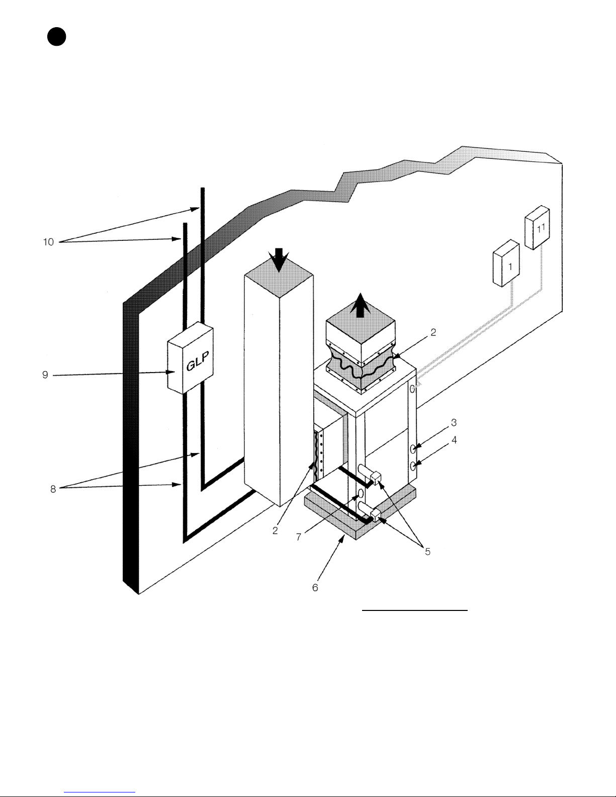
EARTH COUPLED SYSTEMS:
(Figure #12)
Closed loop and pond applications require specialized
design knowledge. No attempt at these installations
should be made unless the dealer has received specialized
training. Utilizing FHP’s Ground Loop Pumping Package
(GLP), makes the installation easy. Anti-freeze solutions
are utilized when low evaporating conditions are
expected to occur. Refer to the GLP installation manuals
for more specific instructions.
SYSTEM CHECKOUT:
• After completing the installation, and before
energizing the unit, the following system checks
should be made:
• Verify that the supply voltage to the heat pump is in
accordance with the nameplate ratings.
• Make sure that all electrical connections are tight and
secure.
• Check the electrical fusing and wiring for the correct
size.
• Verify that the low voltage wiring between the
thermostat and the unit is correct.
• Verify that the water piping is complete and correct.
• Check that the water flow is correct, and adjust if
necessary.
• Check the blower for free rotation, and that it is
secured to the shaft.
• Verify that vibration isolation has been provided.
• Unit is serviceable. Be certain that all access panels are
Page 11
AP SERIES
11
secured in place.
UNIT START-UP:
1. Set the thermostat to the highest setting.
2. Set the thermostat system switch to "COOL", and the
fan switch to the "AUTO" position. The reversing valve
solenoid should energize. The compressor and fan
should not run.
3. Reduce the thermostat setting approximately 5
degrees below the room temperature.
4. Verify the heat pump is operating in the cooling
mode.
5. Turn the thermostat system switch to the "OFF"
position. The unit should stop running and the
reversing valve should deenergize.
6. Leave the unit off for approximately (5) minutes to
allow for system equalization.
7. Turn the thermostat to the lowest setting.
8. Set the thermostat switch to "HEAT".
9. Increase the thermostat setting approximately 5
degrees above the room temperature.
10. Verify the heat pump is operating in the heating
mode.
11. Set the thermostat to maintain the desired space
temperature.
12. Check for vibrations, leaks, etc...
AINTENANCE:
M
1. Filter changes or cleanings are required at regular
intervals. The time period between filter changes will
depend upon type of environment the equipment is
used in. In a single family home, that is not under
construction, changing or cleaning the filter every 60
days is sufficient. In other applications such as motels,
where daily vacuuming produces a large amount of
lint, filter changes may be need to be as frequent as
biweekly.
WARNING: Equipment should never be used during
construction due to likelihood of wall board dust
accumulation in the air coil of the equipment which
permanently affects the performance and may
shorten the life of the equipment.
2. An annual “checkup” is recommended by a licensed
refrigeration mechanic. Recording the performance
measurements of volts, amps, and water temperature
differences (both heating and cooling) is
recommended. This data should be compared to the
information on the unit’s data plate and the data
taken at the original startup of the equipment.
3. Lubrication of the blower motor is not required,
however may be performed on some motors to
extend motor life. Use SAE-20 non-detergent electric
motor oil.
4. The condensate drain should be checked annually by
cleaning and flushing to insure proper drainage.
5. Periodic lockouts almost always are caused by air or
water flow problems. The lockout (shutdown) of the
unit is a normal protective measure in the design of
the equipment. If continual lockouts occur call a
mechanic immediately and have them check for:
water flow problems, water temperature problems,
air flow problems or air temperature problems. Use of
the pressure and temperature charts for the unit may
be required to properly determine the cause.
970-292 Revised 5-12
Page 12
12
AP SERIES
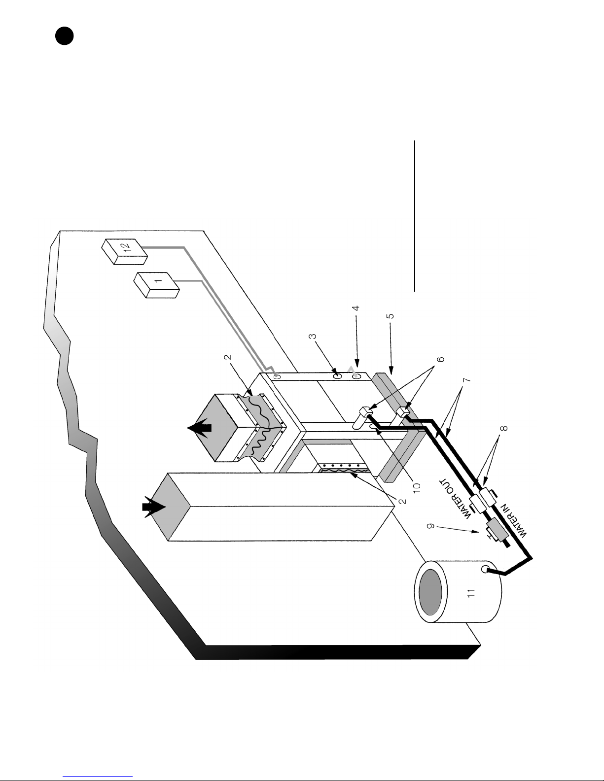
5. VIBRATION PAD
6. P/T PORTS
4. LINE VOLTAGE CONNECTION
7. HOSE KITS (Optional)
8. BALL VALVES
11. PRESSURE TANK (Optional)
3. LOW VOLTAGE CONTROL CONNECTION
2. FLEX DUCT CONNECTION
1. LINE VOLTAGE DISCONNECT (UNIT)
WELL WATER APPLICATIONS (50°F EWT MIN.)
9. SOLENOID VALVE SLOW CLOSING
10. CONDENSATE DRAIN CONNECTION
NOTE: SEE FIGURE #3 FOR CONDENSATE DRAIN CONNECTION
12. LINE VOLTAGE DISCONNECT (ELECTRIC HEATER)
(Figure #10)
970-292 Revised 5-12
Page 13
AP SERIES
AP SERIES
13
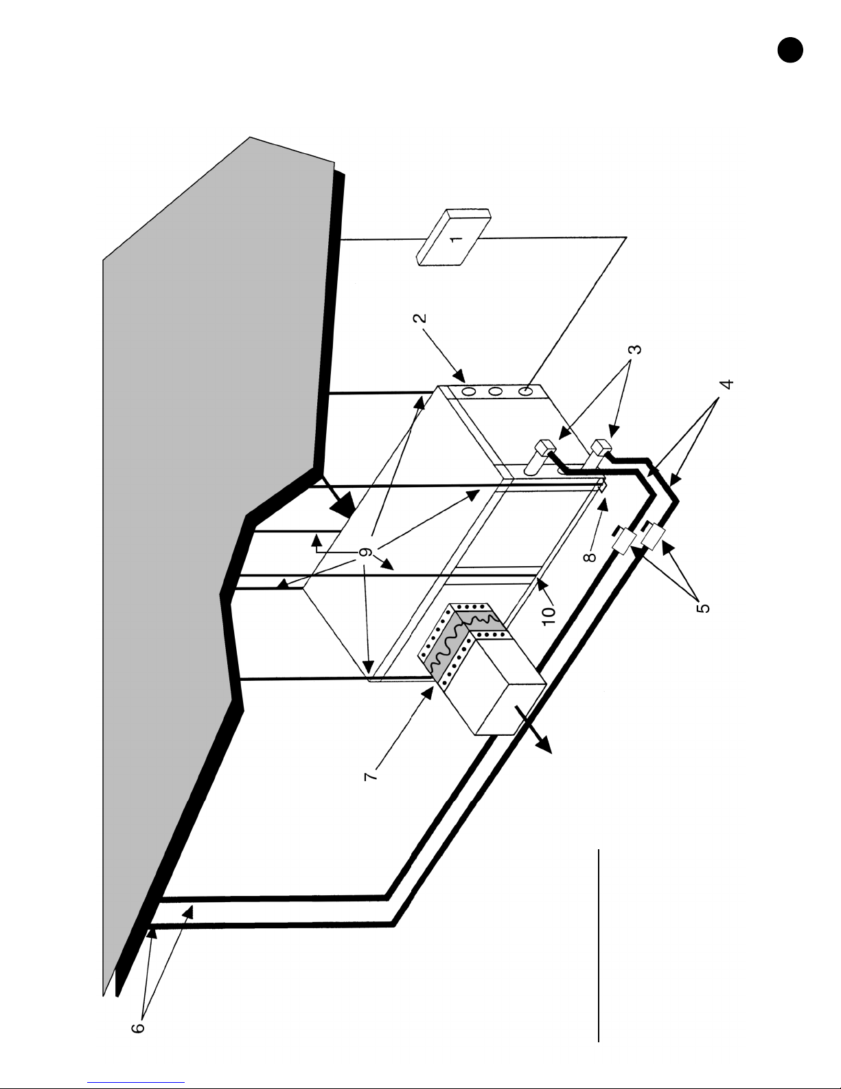
(Figure #11)
970-292 Revised 5-12
4. HOSE KITS (Optional)
5. BALL VALVES
6. SUPPLY AND RETURN LINES OF CENTRAL SYSTEM
3. P/T PLUGS (Optional)
2. LOW VOLTAGE CONTROL CONNECTION
COOLING TOWER/BOILER APPLICATION
1. LINE VOLTAGE DISCONNECT (UNIT)
8. HANGING BRACKETS ASSEMBLY
7. FLEX DUCT CONNECTION
9. THREADED ROD
10. HANGING BRACKET ASSEMBLY
NOTE: SEE FIGURE #3 FOR CONDENSATE DRAIN CONNECTION
Page 14
14
AP SERIES
970-292 Revised 5-12
(Figure #12)
EARTH COUPLED APPLICATION
1. LINE VOLTAGE DISCONNECT (UNIT)
2. FLEX DUCT CONNECTION
3. LOW VOLTAGE CONTROL CONNECTION
4. LINE VOLTAGE CONNECTION (UNIT)
5. P/T PORTS
6. VIBRATION PAD
7. CONDENSATE DRAIN
8. GROUND LOOP CONNECTION KIT (555-000,001)
9. GROUND LOOP PUMPING PACKAGE (GL001-1 or 002-1)
10. POLYETHELENE WITH INSULATION
11. LINE VOLTAGE DISCONNECT (ELECTRIC HEATER)
NOTE: SEE FIGURE #3 FOR CONDENSATE DRAIN CONNECTION
Page 15
AP SERIES
15
970-292 Revised 5-12
Page 16
16
AP SERIES
970-292 Revised 5-12
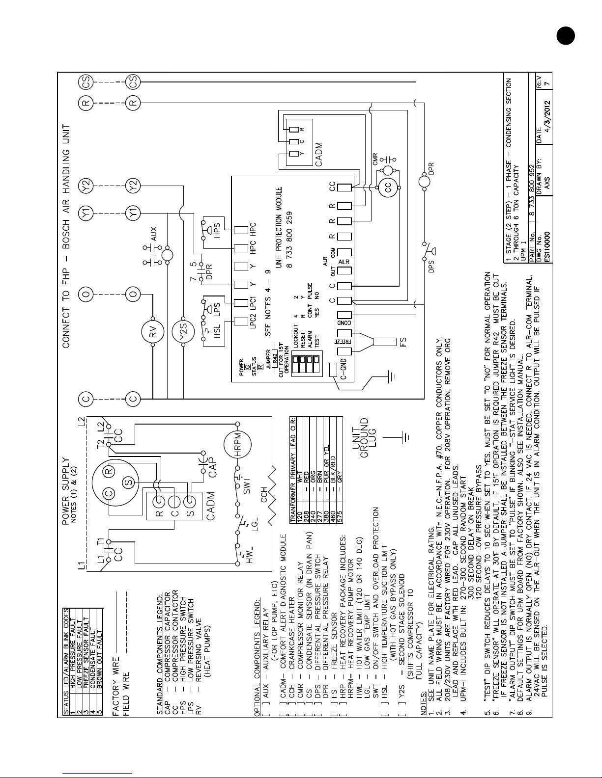
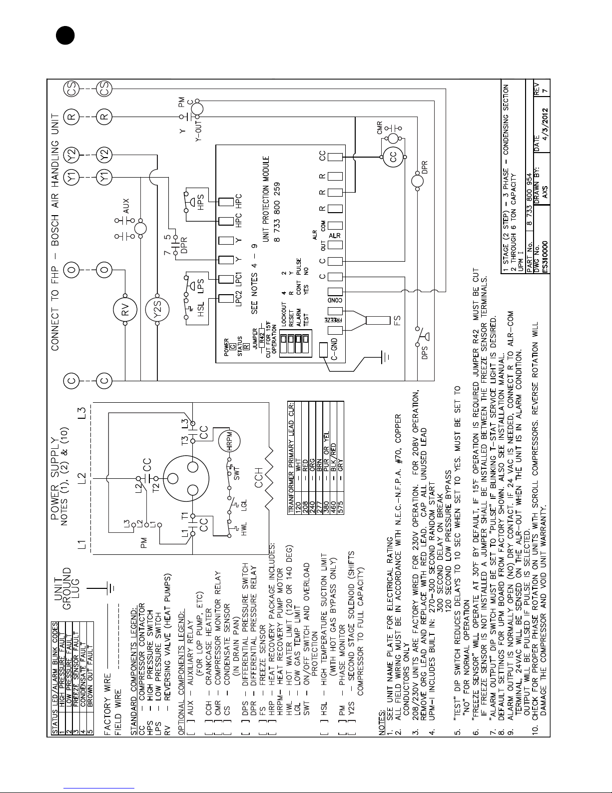
(Figure #13)
Page 17
AP SERIES
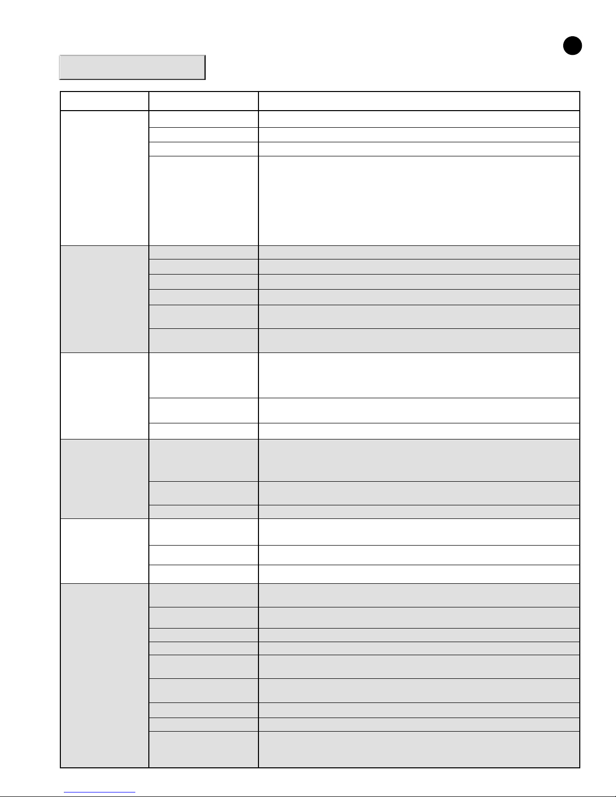
TROUBLE SHOOTING
PROBLEM POSSIBLE CAUSE CHECKS AND CORRECTIONS
17
ENTIRE UNIT DOES
NOT RUN
LOWER OPERATES
B
BUT COMPRESSOR
DOES NOT
UNIT OFF ON
HIGH PRESSURE
CONTROL
UNIT OFF ON
LOW PRESSURE
CONTROL
ower supply off
P
Blown fuse Replace fuse or reset circuit breaker. Check for correct fuses.
oltage supply low
V
Thermostat
Thermostat Check setting, calibration, and wiring.
Wiring Check for loose or broken wires at compressor, capacitor, or contactor.
Safety controls Check UPM board red default L.E.D. for Blink Code
Compressor overload open If the compressor is cool and the overload will not reset, replace compressor.
Compressor motor grounded Internal winding grounded to the compressor shell. Replace compressor. If compressor burnout,
Compressor windings open After compressor has cooled, check continuity of the compressor windings. If the windings are
Discharge pressure too high
Refrigerant charge The unit is overcharged with refrigerant. Reclaim refrigerant, evacuate and recharge with factory
High pressure Check for defective or improperly calibrated high pressure switch.
Suction pressure too low In "COOLING" mode: Lack of or inadequate air flow. Entering air temperature too cold. Blower
Refrigerant charge The unit is low on refrigerant. Check for refrigerant leak, repair, evacuate and recharge with
Low pressure switch Check for defective or improperly calibrated low pressure switch.
pply power, close disconnect
A
f voltage is below minimum voltage specified on unit data plate, contact local power company.
I
et the fan to "ON", the fan should run. Set thermostat to "COOL" and lowest temperature setting,
S
the unit should run in the cooling mode (reversing valve energized). Set unit to "HEAT" and the
highest temperature setting, the unit should run in the heating mode. If neither the blower or
ompressor run in all three cases, the thermostat could be miswired or faulty.To ensure miswired
c
or faulty thermostat verify 24 volts is available on the condensing section low voltage terminal
strip between "R" and "C", "Y" and "C", and "O" and "C". If the blower does not operate, verify 24
olts between terminals "G" and "C" in the air handler. Replace the thermostat if defective.
v
install suction filter dryer.
open, replace the compressor.
In "COOLING" mode: Lack of or inadequate water flow. Entering water temperature too warm.
Scaled or plugged condenser.
In "HEATING" mode: Lack of or inadequate air flow. Blower inoperative, clogged filter or
restrictions in ductwork.
recommended charge.
inoperative, clogged filter, or restrictions in ductwork.
In "HEATING" mode: Lack of or inadequate water flow. Entering water temperature too cold.
Scaled or plugged condenser.
factory recommended charge.
UNIT SHORT
CYCLES
INSUFFICIENT
COOLING OR
HEATING
Unit oversized Recalculate heating and or cooling loads.
Thermostat Thermostat installed near a supply air grill, relocate thermostat. Readjust heat anticipator.
Wiring and controls Loose connections in the wiring or a defective compressor contactor.
Unit undersized Recalculate heating and or cooling loads. If excessive, possibly adding insulation and shading will
Loss of conditioned air
by leaks
Airflow Lack of adequate air flow or improper distribution of air. Replace dirty filter.
Refrigerant charge Low on refrigerant charge causing inefficient operation.
Compressor
Reversing valve Defective reversing valve creating bypass of refrigerant from discharge to suction side of
Operating pressures Compare unit operating pressures to the pressure / temperature chart for the unit.
TXV Check TXV for possible restriction or defect. Replace if necessary.
Moisture, noncondensables The refrigerant system may be contaminated with moisture or noncondensables. Reclaim
970-292 Revised 5-12
rectify the problem.
Check for leaks in duct work or introduction of ambient air through doors or windows.
Check for defective compressor. If discharge is too low and suction pressure is too high,
compressor is not pumping properly. Replace compressor.
compressor. Replace reversing valve.
refrigerant, evacuate and recharge with factory recommended charge. Note: a liquid line dryer
may be required.
Page 18
18
UNIT CHECK-OUT
SHEET
Customer Data
Customer Name ______________________________________________ Date _________________________________
Address _____________________________________________________
_____________________________________________________
Phone ______________________________________________________ Unit Number __________________________
Unit Nameplate Data
Unit Make _________________________________________
Model Number_____________________________________ Serial Number_________________________________
Refrigerant Charge (oz) ________
Compressor: RLA _____________ LRA ______________
Blower Motor: FLA (or NPA) ____________ HP_______________
Maximum Fuse Size (Amps) ___________
Minimum Circuit Ampacity (Amps) ______________
AP SERIES
Operating Conditions
Cooling Mode Heating Mode
Entering / Leaving Air Temp _______________ /_______________ _______________ /_______________
Entering Air Measured at: _______________________________ _______________________________
Leaving Air Measured at: _______________________________ _______________________________
Entering / Leaving Fluid Temp _______________ /_______________ _______________ /_______________
Compressor Volts / Amps _______________ /_______________ _______________ /_______________
Blower Motor Volts / Amps _______________ /_______________ _______________ /_______________
Fluid Flow (gpm)* _______________________________ _______________________________
Fluid Side Pressure Drop* _______________________________ _______________________________
Suction / Discharge Pressure (psig)* _______________ /_______________ _______________ /_______________
Suction / Discharge Temp* _______________/_______________ _______________ /_______________
Suction Superheat* _______________________________ _______________________________
Entering TXV / Cap Tube Temp* _______________________________ _______________________________
Liquid Subcooling* _______________________________ _______________________________
* Required for Troubleshooting ONLY
Auxiliary Heat
Unit Make _________________________________________
Model Number _____________________________________ Serial Number ________________________________
Max Fuse Size (Amps) _______________________________
Volts / Amps_____________________ /____________________
Entering Air Temperature ____________________________
Leaving Air Temperature _____________________________
970-292 Revised 5-12
Page 19
AP SERIES
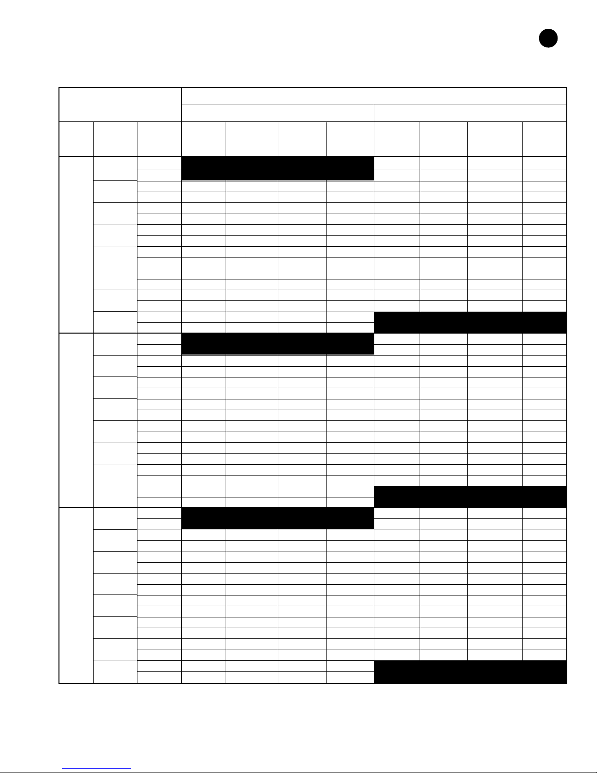
Operating Pressures & Temperatures
Environmentally Safe R-410A Refrigerant
OPERATING DATA
OOLING HEATING
C
19
ODEL WATER FLOW PRESSURE PRESSURE TEMP TEMP PRESSURE PRESSURE TEMP TEMP
M
AP025
Part
Load
AP025
Full
Load
AP035
Part
Load
ENTERING WATER SUCTION DISCHARGE WATER AIR SUCTION DISCHARGE WATER AIR
TEMP. ˚F GPM PSIG PSIG RISE ˚F DROP ˚F PSIG PSIG DROP ˚F RISE ˚F
30˚
40˚
50˚
60˚
70˚
80˚
90˚
100˚
30˚
40˚
50˚
60˚
70˚
80˚
90˚
100˚
30˚
40˚
50˚
60˚
70˚
80˚
90˚
100˚
4
8 79-96 270-331 3-4 16-18
4 120-146 186-228 14-17 18-21 88-107 277-339 6-7 17-20
8 115-140 175-214 8-9 19-23 92-112 284-348 4-5 18-21
4 129-157 218-267 14-17 18-20 98-122 291-356 7-8 20-23
8 124-151 204-250 8-9 19-22 110-130 298-364 5-6 21-24
4 134-163 249-305 13-16 17-20 112-136 304-372 8-10 22-26
8 128-156 233-287 8-9 18-21 117-143 312-381 6-7 23-28
4 138-168 281-341 13-16 17-19 124-152 318-389 9-11 24-29
8 133-161 263-323 7-9 18-21 131-159 325-398 6-8 26-31
4 143-174 317-388 13-16 16-19 136-166 331-405 11-13 27-32
8 137-167 297-366 7-9 17-20 143-174 339-415 7-9 28-33
4 147-179 357-437 13-16 16-18 149-181 345-422 12-14 29-35
8 141-172 335-411 7-9 17-20 156-190 352-432 8-10 31-37
4 151-185 402-492 13-15 15-18
8 146-177 378-459 7-9 16-19
4 76-92 242-297 3-4 13-14
8 80-97 249-304 2-3 13-15
4 125-151 180-221 14-18 19-22 89-108 255-312 4-5 15-17
8 120-146 169-207 8-10 20-23 93-113 261-320 3-3 16-18
4 134-163 211-258 14-18 18-21 106-118 267-327 5-6 17-19
8 129-157 198-242 8-10 19-23 104-112 274-335 3-4 18-21
4 139-169 241-295 14-17 18-21 113-138 280-342 6-7 19-22
8 134-163 227-278 8-10 19-22 119-145 287-351 4-5 20-23
4 144-175 272-333 14-17 17-20 126-155 292-358 7-8 21-24
8 138-168 255-313 8-10 18-21 133-162 300-367 5-6 22-26
4 148-181 307-375 14-17 17-19 138-168 305-373 8-9 23-27
8 143-174 288-353 8-10 18-21 145-177 312-382 5-6 24-29
4 153-186 346-423 14-17 16-19 151-184 317-388 8-10 25-29
8 147-179 325-398 8-9 17-20 158-193 325-398 6-7 26-31
4 158-191 389-477 13-16 16-18
8 152-185 366-448 8-9 17-20
4.5 73-89 266-325 5-6 15-18
9.0 77-94 272-333 3-4 16-19
4.5 117-143 189-231 14-17 18-22 86-105 279-341 6-7 17-21
9.0 112-137 178-217 8-9 19-24 90-110 286-350 4-5 18-22
4.5 126-154 221-270 14-17 18-21 105-125 293-358 7-8 20-24
9.0 121-148 207-253 8-9 19-23 170-208 300-366 5-6 21-25
4.5 131-160 252-308 13-16 17-21 110-134 306-374 8-10 22-27
9.0 125-153 237-290 8-9 18-22 115-141 314-383 6-7 23-29
4.5 135-165 284-347 13-16 17-20 122-150 320-391 9-11 24-30
9.0 130-158 266-326 7-9 18-22 129-157 327-400 6-8 26-32
4.5 140-171 320-391 13-16 16-20 134-164 333-407 11-13 27-33
9.0 134-164 300-367 7-9 17-21 141-172 341-417 7-9 28-35
4.5 144-176 360-440 13-16 16-19 147-179 347-424 12-14 29-36
9.0 138-169 338-414 7-9 17-21 154-188 355-434 8-10 31-38
4.5 149-182 405-495 13-15 15-19
9.0 143-174 381-465 7-9 16-20
75-91 264-322 5-6 15-17
This chart shows approximate temperatures and pressures for a unit in good repair. The values shown are meant as a guide only and should not be used to estimate system
charge. This chart assumes rated air flow and 80º d.b./67º w.b. entering air temperature in cooling, 70º d.b. entering air temperature in heating. Heating data at entering fluid
temperatures below 50º assumes the use of antifreeze.
As a result of continuing research and development, specifications are subject to change without notice.
970-292 Revised 5-12
Page 20
20
AP SERIES
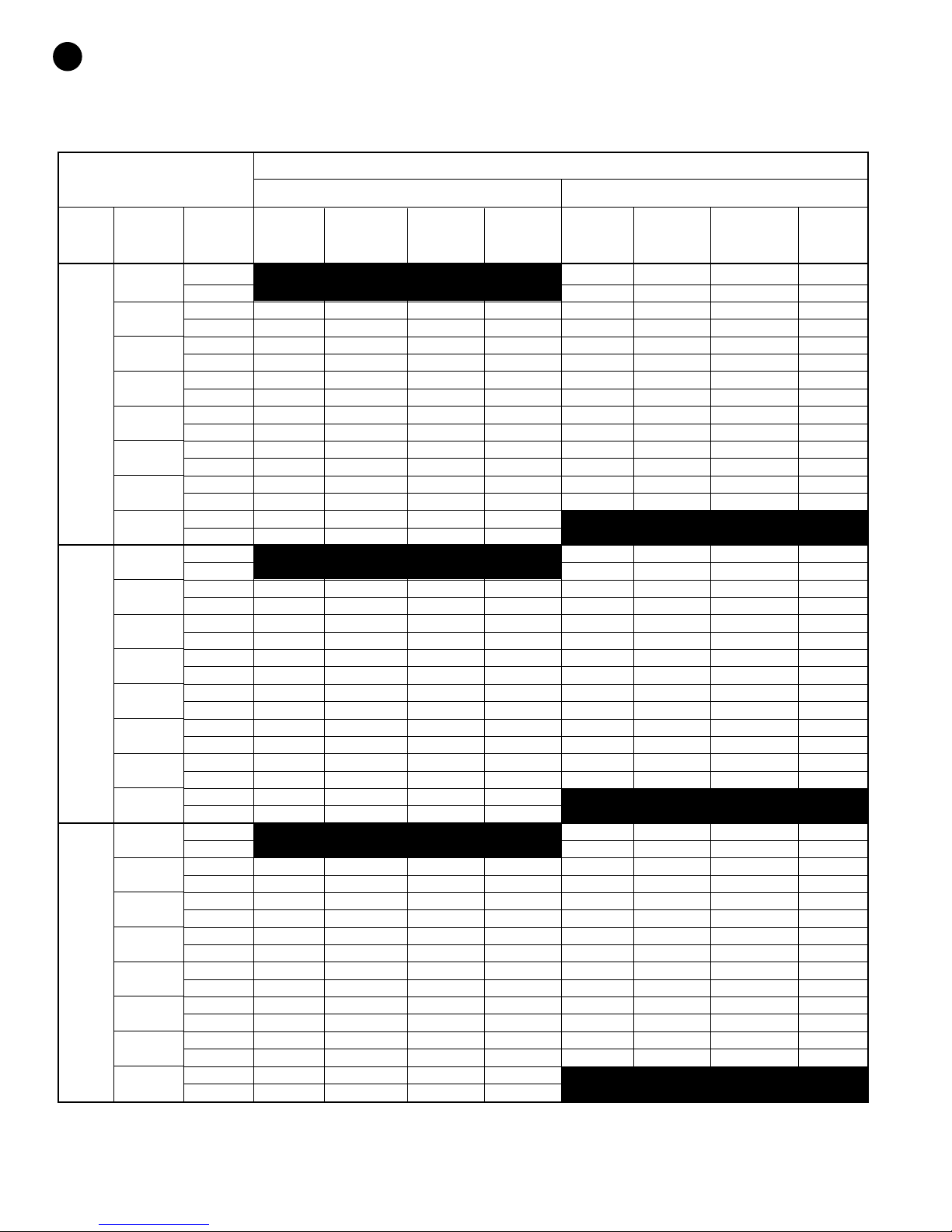
Operating Pressures & Temperatures
Environmentally Safe R-410A Refrigerant
OPERATING DATA
COOLING HEATING
NTERING WATER SUCTION DISCHARGE WATER AIR SUCTION DISCHARGE WATER AIR
MODEL WATER FLOW PRESSURE PRESSURE TEMP TEMP PRESSURE PRESSURE TEMP TEMP
AP035
Full
Load
AP049
Part
Load
AP049
Full
Load
E
EMP. ˚F GPM PSIG PSIG RISE ˚F DROP ˚F PSIG PSIG DROP ˚F RISE ˚F
T
30˚
40˚
50˚
60˚
70˚
80˚
90˚
100˚
30˚
40˚
50˚
60˚
70˚
80˚
90˚
100˚
30˚
40˚
50˚
60˚
70˚
80˚
90˚
100˚
4.5 74-90 244-299 3-4 13-15
9.0 78-95 251-306 2-3 13-16
4.5 122-149 183-224 14-18 19-23 87-106 257-314 4-5 15-18
9.0 117-143 172-210 8-10 20-24 91-111 263-322 3-3 16-19
4.5 131-160 214-261 14-18 18-22 95-105 269-329 5-6 17-20
9.0 126-154 201-245 8-10 19-24 100-125 276-337 3-4 18-22
4.5 136-166 244-298 14-17 18-22 111-136 282-344 6-7 19-23
9.0 131-160 230-281 8-10 19-23 117-143 289-353 4-5 20-24
4.5 141-172 275-336 14-17 17-21 124-152 294-360 7-8 21-25
9.0 135-165 258-316 8-10 18-22 131-160 302-369 5-6 22-27
4.5 145-178 310-378 14-17 17-20 136-166 307-375 8-9 23-28
9.0 140-171 291-356 8-10 18-22 143-175 314-384 5-6 24-30
4.5 150-183 349-426 14-17 16-20 149-182 319-390 8-10 25-30
9.0 144-176 328-401 8-9 17-21 156-191 327-400 6-7 26-32
4.5 155-189 392-480 13-16 16-19
9.0 149-182 369-451 8-9 17-21
6.0 64-78 248-303 5-6 15-18
12.0 67-82 254-311 3-4 16-19
6.0 109-134 183-224 18-22 19-23 75-91 261-319 6-8 17-21
12.0 105-128 172-210 10-12 20-25 79-96 267-327 4-5 18-23
6.0 118-144 214-261 18-22 19-23 78-90 273-334 8-10 20-24
12.0 113-138 201-245 10-12 20-24 82-95 280-342 5-7 21-26
6.0 122-149 244-298 17-21 18-22 96-117 286-349 9-11 22-27
12.0 117-143 230-281 10-12 19-24 102-123 293-358 6-8 24-29
6.0 126-154 275-336 17-21 18-22 107-131 299-365 11-13 25-30
12.0 121-148 258-316 10-12 19-23 113-138 306-374 7-9 26-32
6.0 130-159 310-378 17-21 17-21 117-143 311-380 12-15 27-33
12.0 132-153 291-356 10-12 18-22 123-151 319-390 8-10 29-35
6.0 134-164 349-426 17-20 17-20 128-157 324-396 13-16 29-36
12.0 129-158 328-401 9-12 18-22 135-165 332-406 9-11 31-38
6.0 139-170 392-480 16-20 16-20
12.0 133-163 369-451 9-11 17-21
6.0 71-87 277-339 6-7 15-19
12.0 75-92 284-347 4-5 16-20
6.0 118-144 194-237 21-25 19-23 84-102 291-356 7-9 18-22
12.0 113-138 182-223 12-14 20-24 88-108 299-365 5-6 19-23
6.0 127-155 226-276 21-25 18-22 92-110 305-373 9-11 20-25
12.0 122-149 213-260 12-14 19-24 98-120 313-383 6-7 21-26
6.0 131-160 259-316 21-25 18-22 108-132 320-391 10-13 23-28
12.0 126-154 243-297 12-14 19-23 113-138 328-400 7-9 24-29
6.0 136-166 291-355 20-25 17-21 120-147 334-408 12-15 25-31
12.0 130-159 273-334 12-14 18-22 126-154 342-418 8-10 27-32
6.0 140-171 328-401 20-24 17-20 131-161 348-425 14-17 27-34
12.0 135-165 308-377 11-14 18-22 138-169 356-436 9-11 29-36
6.0 145-177 369-451 20-24 16-20 144-176 362-442 15-18 30-37
12.0 139-170 347-424 11-14 17-21 151-185 371-453 10-12 32-39
6.0 149-183 415-508 19-24 16-19
12.0 143-175 391-477 11-14 17-21
This chart shows approximate temperatures and pressures for a unit in good repair. The values shown are meant as a guide only and should not be used to estimate system
charge. This chart assumes rated air flow and 80º d.b./67º w.b. entering air temperature in cooling, 70º d.b. entering air temperature in heating. Heating data at entering fluid
temperatures below 50º assumes the use of antifreeze.
As a result of continuing research and development, specifications are subject to change without notice.
970-292 Revised 5-12
Page 21
AP SERIES
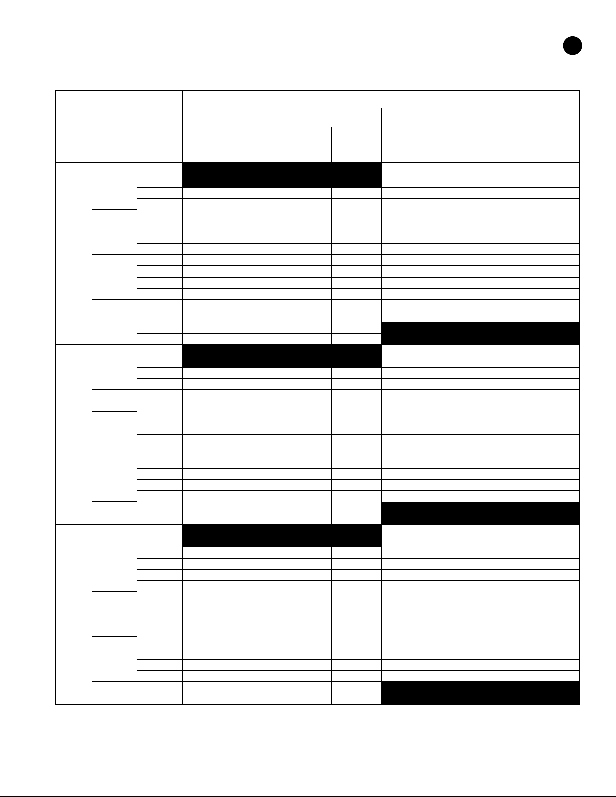
Operating Pressures & Temperatures
Environmentally Safe R-410A Refrigerant
OPERATING DATA
COOLING HEATING
NTERING WATER SUCTION DISCHARGE WATER AIR SUCTION DISCHARGE WATER AIR
ODEL WATER FLOW PRESSURE PRESSURE TEMP TEMP PRESSURE PRESSURE TEMP TEMP
M
AP061
Part
Load
AP061
Full
Load
AP071
Part
Load
E
TEMP. ˚F GPM PSIG PSIG RISE ˚F DROP˚ F PSIG PSIG DROP ˚F RISE ˚F
30˚
40˚
50˚
60˚
70˚
80˚
90˚
100˚
30˚
40˚
50˚
60˚
70˚
80˚
90˚
100˚
30˚
40˚
50˚
60˚
70˚
80˚
90˚
100˚
7.0 68-84 256-313 5-7 19-23
4.0 73-89 261-319 4-5 20-25
1
7.0 113-138 172-210 18-22 19-23 81-99 277-339 7-8 22-26
14.0 110-134 161-196 12-14 20-24 86-105 283-346 5-6 23-28
7.0 116-142 206-252 17-21 19-23 93-114 299-365 8-9 24-29
14.0 112-137 193-236 12-14 19-24 99-121 305-373 6-7 25-31
7.0 118-145 241-294 17-21 18-23 106-129 321-392 9-11 26-32
14.0 115-140 225-275 11-14 19-23 113-138 327-400 7-8 28-34
7.0 121-148 275-336 17-21 18-22 118-145 342-418 10-12 29-35
14.0 117-143 257-314 11-14 19-23 126-154 349-427 8-9 30-37
7.0 123-151 309-378 16-20 18-22 131-160 364-444 11-14 31-38
14.0 120-146 289-353 11-13 19-23 139-170 371-454 8-10 33-40
7.0 126-154 344-420 16-20 18-22 143-175 385-471 12-15 33-41
14.0 122-149 321-392 11-13 18-22 152-186 393-480 9-11 35-43
7.0 128-157 378-462 16-19 17-21
14.0 125-152 353-432 11-13 18-22
7.0 68-84 256-313 5-7 19-23
14.0 73-89 261-319 4-5 20-25
7.0 117-143 182-222 15-19 21-26 81-99 277-339 7-8 22-26
14.0 114-139 170-208 11-14 22-27 86-105 283-346 5-6 23-28
7.0 120-147 215-263 15-18 20-25 93-114 299-365 8-9 24-29
14.0 117-143 201-246 11-14 21-26 99-121 305-373 6-7 25-31
7.0 123-150 248-304 14-17 20-24 106-129 321-392 9-11 26-32
14.0 119-146 232-284 11-13 21-25 113-138 327-400 7-8 28-34
7.0 126-154 282-344 14-17 19-24 118-145 342-418 10-12 29-35
14.0 122-149 263-322 10-13 20-25 126-154 349-427 8-9 30-37
7.0 129-157 315-385 13-16 19-23 131-160 364-444 11-14 31-38
14.0 125-153 294-360 10-12 19-24 139-170 371-454 8-10 33-40
7.0 132-161 348-426 13-16 18-22 143-175 385-471 12-15 33-41
14.0 128-156 326-398 10-12 19-23 152-186 393-480 9-11 35-43
7.0 134-164 382-466 12-15 17-21
14.0 131-160 357-436 9-11 18-22
9.0 71-87 259-316 5-7 19-23
18.0 76-92 264-322 4-5 20-25
9.0 116-141 175-213 18-22 19-23 84-102 280-342 7-8 22-26
18.0 113-137 164-199 12-14 20-24 89-108 286-349 5-6 23-28
9.0 119-145 209-255 17-21 19-23 96-117 302-368 8-9 24-29
18.0 115-140 196-239 12-14 19-24 102-124 308-376 6-7 25-31
9.0 121-148 244-297 17-21 18-23 109-132 324-395 9-11 26-32
18.0 118-143 228-278 11-14 19-23 116-141 330-403 7-8 28-34
9.0 124-151 278-339 17-21 18-22 121-148 345-421 10-12 29-35
18.0 120-146 260-317 11-14 19-23 129-157 352-430 8-9 30-37
9.0 126-154 312-381 16-20 18-22 134-163 367-447 11-14 31-38
18.0 123-149 292-356 11-13 19-23 142-173 374-457 8-10 33-40
9.0 129-157 347-423 16-20 18-22 146-178 388-474 12-15 33-41
18.0 125-152 324-395 11-13 18-22 155-189 396-483 9-11 35-43
9.0 131-160 381-465 16-19 17-21
18.0 128-155 356-435 11-13 18-22
21
This chart shows approximate temperatures and pressures for a unit in good repair. The values shown are meant as a guide only and should not be used to estimate system
charge. This chart assumes rated air flow and 80º d.b./67º w.b. entering air temperature in cooling, 70º d.b. entering air temperature in heating. Heating data at entering fluid
temperatures below 50º assumes the use of antifreeze.
As a result of continuing research and development, specifications are subject to change without notice.
Page 22
22
AP SERIES
Operating Pressures & Temperatures
Environmentally Safe R-410A Refrigerant
OPERATING DATA
COOLING HEATING
NTERING WATER SUCTION DISCHARGE WATER AIR SUCTION DISCHARGE WATER AIR
MODEL WATER FLOW PRESSURE PRESSURE TEMP TEMP PRESSURE PRESSURE TEMP TEMP
AP071
Full
Load
E
TEMP. ˚F GPM PSIG PSIG RISE ˚F DROP ˚F PSIG PSIG DROP ˚F RISE ˚F
30˚
40˚
50˚
60˚
70˚
80˚
90˚
100˚
9.0 71-87 259-316 5-7 19-23
18.0 76-92 264-322 4-5 20-25
9.0 120-146 185-225 15-19 21-26 84-102 280-342 7-8 22-26
18.0 117-142 173-211 11-14 22-27 89-108 286-349 5-6 23-28
9.0 123-150 218-266 15-18 20-25 96-117 302-368 8-9 24-29
18.0 120-146 204-249 11-14 21-26 102-124 308-376 6-7 25-31
9.0 126-153 251-307 14-17 20-24 109-132 324-395 9-11 26-32
18.0 122-149 235-287 11-13 21-25 116-141 330-403 7-8 28-34
9.0 129-157 285-347 14-17 19-24 121-148 345-421 10-12 29-35
18.0 125-152 266-325 10-13 20-25 129-157 352-430 8-9 30-37
9.0 132-160 318-388 13-16 19-23 134-163 367-447 11-14 31-38
18.0 128-156 297-363 10-12 19-24 142-173 374-457 8-10 33-40
9.0 135-164 351-429 13-16 18-22 146-178 388-474 12-15 33-41
18.0 131-159 329-401 10-12 19-23 155-189 396-483 9-11 35-43
9.0 137-167 385-469 12-15 17-21
18.0 134-163 360-439 9-11 18-22
This chart shows approximate temperatures and pressures for a unit in good repair. The values shown are meant as a guide only and should not be used to estimate system
charge. This chart assumes rated air flow and 80º d.b./67º w.b. entering air temperature in cooling, 70º d.b. entering air temperature in heating. Heating data at entering fluid
temperatures below 50º assumes the use of antifreeze.
As a result of continuing research and development, specifications are subject to change without notice.
970-292 Revised 5-12
Page 23

AP SERIES
Notes
23
970-292 Revised 5-12
Page 24
601 N.W. 65th Court, Ft. Lauderdale, FL 33309
Phone: 954-776-5471 | Fax: 954-776-5529
www.boschtaxcredit.com | www.fhp-mfg.com
970-292 Revised 5-12
 Loading...