

Page 1
INSTALLATION GUIDE
EN
NOTICE D’INSTALLATION
FR
Page 2

IMPORTANT
Dimensions in parentheses are in inches: mm(in).
Weights in parentheses are in pounds: kg (lb).
Temperatures in parentheses are in Fahrenheit degrees: °C(°F)
Page 3

Page
Installation Guide
Index
Important Instructions
3
Important safety instructions
Children safety
Technical requirements
10
13
14
16
17
18
19
20
21
22
23
3
4
5
6
Appliance features and installation requirements
Integrated installation niche features
StandPlus installation niche features
X-Pro installation niche features
Preparing to install
7
8
8
9
Transport to installation site and unpacking
Niche Dimensions a n d I n s t a l l a t i o n S t y l e s : I n t e g r a t e d S e r i e s
Niche Dimensions and Installation Styles: StandPlus and X-Pro Series
Installation types
Electrical and Water connection
Levelling
EnglishFrançais
Panels mounting
Decorative door and Bottom-Drawer panels layout
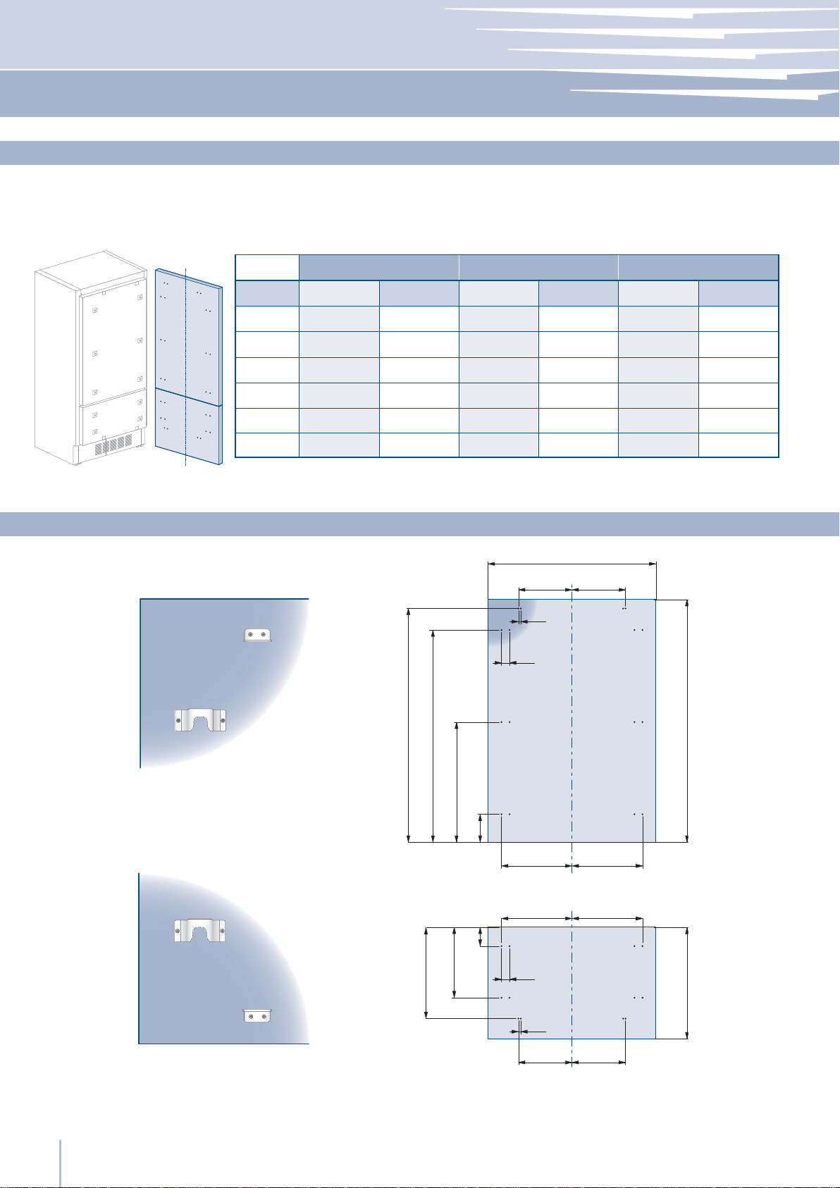
Decorative panels layout for Fridge with one Bottom-Drawer
Decorative panels layout for Fridge with two Bottom-Drawers
Decorative panels layout for Fridge with Glass door and one Bottom-Drawer
Decorative panels layout for Fridge with Glass door and two Bottom-Drawers
Panels Dimensions One Bottom - Drawer
Panels Dimensions Two Bottom - Drawers
Mounting the handles on Integrated units
Mounting panels to the door and the drawer of Integrated units
25
26
28
30
31
32
33
34
Installation
Built-in installation of single appliance
Built-in installation of two or more appliances
Completing the installation
Anti-tipping safety assembly
Mounting handles on stainless front
Air circulation
Ventilation
Post installation control
Start Up
www.fhiaba.com · www.thevettagroup.com
1
Page 4

www.fhiaba.com · www.thevettagroup.com
2
Page 5
Installation Guide
Series: All
Important safely instruction
Symbols used in the Guide
Appliance dimensions
Integrated
Note
Tips for the correct use of the appliance
Important
Directions to avoid appliance damage
Warning
directions to prevent injury
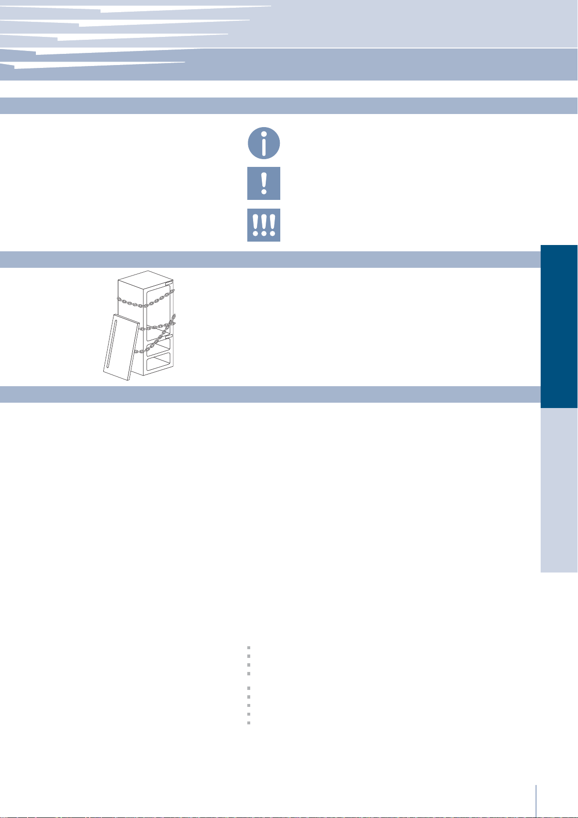
Children safety
If this appliance is replacing an existing appliance which must be
removed or disposed of, make sure that it does not become a
dangerous trap for children by cutting its power supply cable and
rendering it impossible to close the door.
Use the same caution at the end of the lifespan of the new appliance.
EnglishFrançais
Appliance features and installation requirements
FI24 w: 599 mm (23 5/8”)/ h: 2120 mm (83 1/2”)/ d: 610 mm (24”)
FI30 w: 749 mm (29 1/2”)/ h: 2120 mm (83 1/2”)/ d: 610 mm (24”)
FI36 w: 899 mm (35 3/8”)/ h: 2120 mm (83 1/2”)/ d: 610 mm (24”)
Appliance dimensions
StandPlus
Appliance dimensions
X-Pro
Appliance dimensions
with packaging
Weight with packaging
Voltage
Power supply cable
Potable water supply pressure
Water supply tube
Provided installation accessories
Additional equipment necessary
FM24 w: 599 mm (23 5/8”)/ h: 2120 mm (83 1/2”)/ d : 629 mm (24 3/4”)
FM36 w: 899 mm (35 3/8”)/h: 2120 mm (83 1/2”)/ d: 629 mm (24 3/4”)
FP24 w: 599 mm (23 5/8”)/ h: 2120 mm (83 1/2”)/ d: 635 mm (25”)
FP30 w: 749 mm (29 1/2”)/ h: 2120 mm (83 1/2”)/ d: 635 mm (25”)
FP36 w: 899 mm (35 3/8”)/ h: 2120 mm (83 1/2”)/ d: 635 mm (25”)
24” Se r i e s w : 650 mm (25 5/8”) / h: 2260 mm (89”) / d: 800 mm (31 1/2”)
30” Se r i e s w : 800 mm (31 1/2”) / h: 2260 mm (89”) / d: 800 mm (31 1/2”)
36” Se r i e s w : 950 mm (37 3/8”) / h: 2260 mm (89”) / d: 800 mm (31 1/2”)
24” Series up to 230 kg (507 lb)
30” Series up to 275 kg (606 lb)
36” Series up to 295 kg (650 lb)
North America Version: 110V 60Hz
North America Version: 15 A
from 0.05 MPa to 0.5 MPa (0.5 Bar - 5 Bar)
3/4” female attachment
Customized panels mounting Kit
Anti-tipping Kit (B04000200)
Lateral connecting kit (KCLIT/KCLIH)
4 mm (1/8”) allen wrench
Phillips head screwdriver
wood and percussion drill
2.5 mm (1/8”) bit for wood
8 mm (3/8”) bit for walls
17 mm (3/4”) wrench
Adjusting height of the rear rollers
13 mm (1/2”) socket
www.fhiaba.com · www.thevettagroup.com
3
Page 6
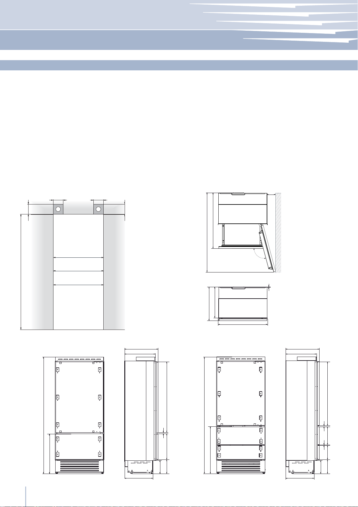
Installation niche features: Integrated Series
A
area to be left clear for the anti-tipping brackets
Niche Height
2134 mm (84”)
Niche Width
FI36: 900 mm (35 1/2”)
FI30: 750 mm (29 5/8”)
FI24: 600 mm (23 3/4”)
Door Swing Clearance
FI36: 1470 mm (57 7/8”)
FI30: 1320 mm (52”)
FI24: 1170 mm (46”)
Door Opening Angle
105°
Width
FI36: 899 mm (35 3/8”)
FI30: 749 mm (29 1/2”)
FI24: 599 mm (23 5/8”)
Height
2120 mm (83 1/2”) + 25 mm (1”)
Depth with door (without panel)
610 mm (24”)
140 (5 ½”) 140 (5 ½”)
100 (4”)
min 2134 (84”)
A A
FI36: 900 (35 ½”)
FI30: 750 (29 5⁄8”)
FI24: 600 (23 ¾”)
100 (4”)
610 (24”)
560 (22”)
992 (39”)
FI30: 1320 (52”)
FI24: 1170 (46”)
FI36: 1470 (57 7⁄8”)
560 (22”)
610 (24”)
FI36: 160 (6 3⁄8”)
FI30: 125 (5”)
FI24: 90 (3 ½”)
105°
10 (3⁄8”)
FI36: 899 (35 3⁄8”)
FI30: 749 (29 ½”)
FI24: 599 (23 5⁄8”)
610 (24”)
560 (22”)
2120 (83 ½”) +25 (1”)
721 (28 3⁄8”) +25 (1”)
www.fhiaba.com · www.thevettagroup.com
4
1293 (50 7⁄8” )
20 (¾”)
474 (18 5⁄8”)
25 (1”)
+ 25 (1”)
500 (19 ¾”) 500 (19 ¾”)
) +
)
1⁄8”
¾”
231 (9
248 (9
2120 (83 ½”) +25 (1”)
846 (33 ¼”) +25 (1”)
1168(46”)
20 (¾”)10 (3⁄8”)
25 (1”)
+ 25 (1”)
) +
)
1⁄8”
¾”
231 (9
248 (9
330 (13”)
)
¼”
259 (10
Page 7
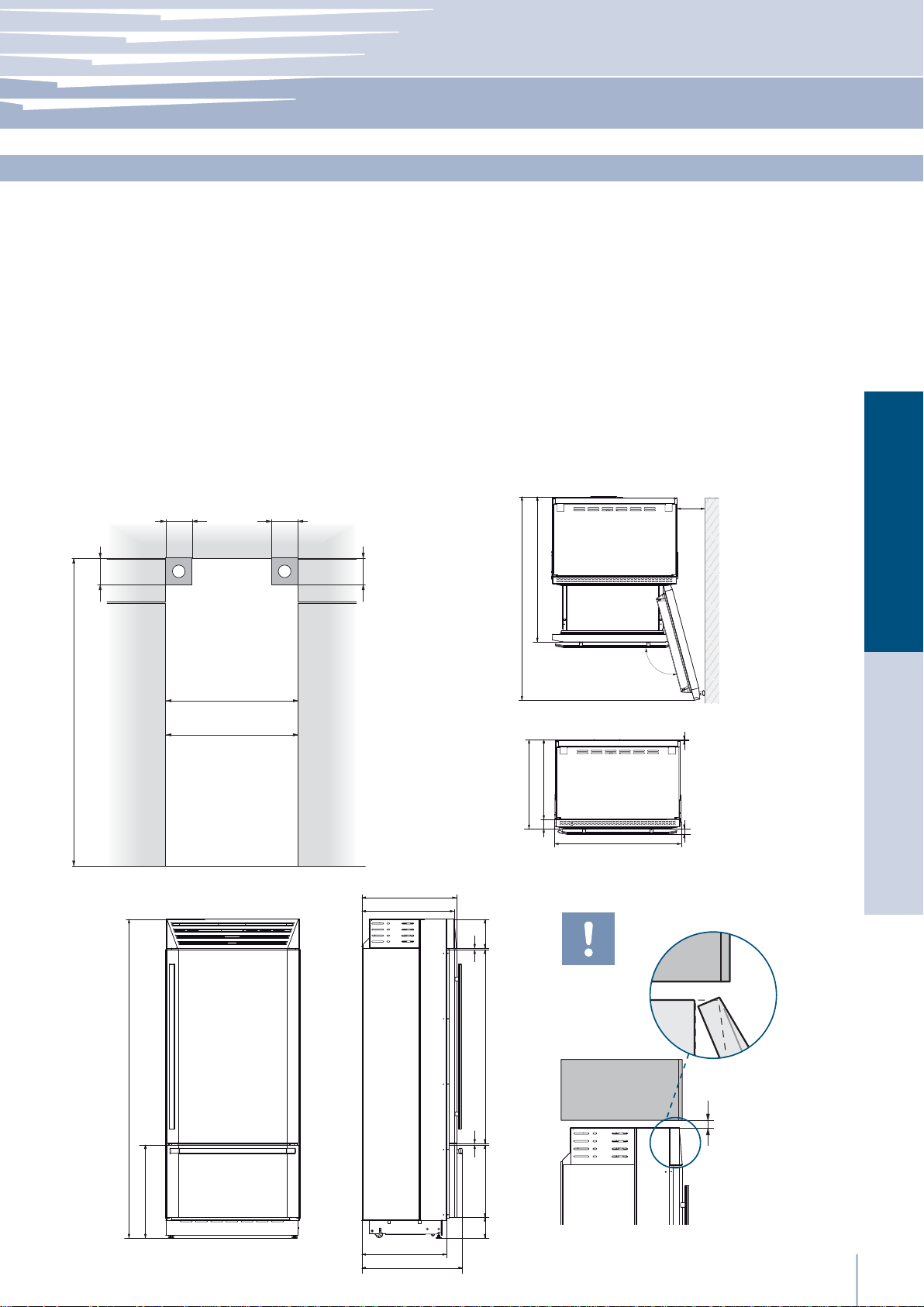
Installation niche features: StandPlus Series
A
area to be left clear for the anti-tipping brackets
Niche Height
2134 mm (84”)
Niche Width
FM36: 900 mm (35 1/2”)
FM24: 600 mm (23 3/4”)
Door Swing Clearance
FM36: 1470 mm (57 7/8”)
FM24: 1170 mm (46”)
Installation Guide
Door Opening Angle
105°
Width
FM36: 899 mm (35 3/8”)
FM24: 599 mm (23 5/8”)
Height
2120 mm (83 1/2”) + 25 mm (1”)
Depth with door
629 mm (24 3/4”)
140 (5 ½”) 140 (5 ½”)
100 (4”)
min 2134 (84”)
A A
FM36: 900 (35 ½”)
FM24: 600 (23 ¾”)
100 (4”)
629 (24 ¾”)
615 (24 ¼”)
FM36: 230 (9”)
FM24: 160 (6 ¼”)
EnglishFrançais
1010 (39 ¾”)
FM24: 1170 (46”)
FM36: 1470 (57 7⁄8”)
105°
10 (3⁄8”)
560 (22”)
629 (24 ¾”)
FM36: 899 (35 5⁄8”)
FM24: 599 (23 5⁄8”)
69 (2 ¾”)
IMPORTANT
8 (3⁄8”)
195 (7 5⁄8”)
37 (1 ½”)
2120 (83 ½”) +25 (1”)
613 (24 1⁄8”)+25 (1”)
560 (22”)
666 (26 ¼”)
1296 (50”)
8 (3⁄8”)
485 (19 1⁄8”)
128 (5) + 25 (1”)
Flush
min 10 (3⁄8”)
www.fhiaba.com · www.thevettagroup.com
5
Page 8
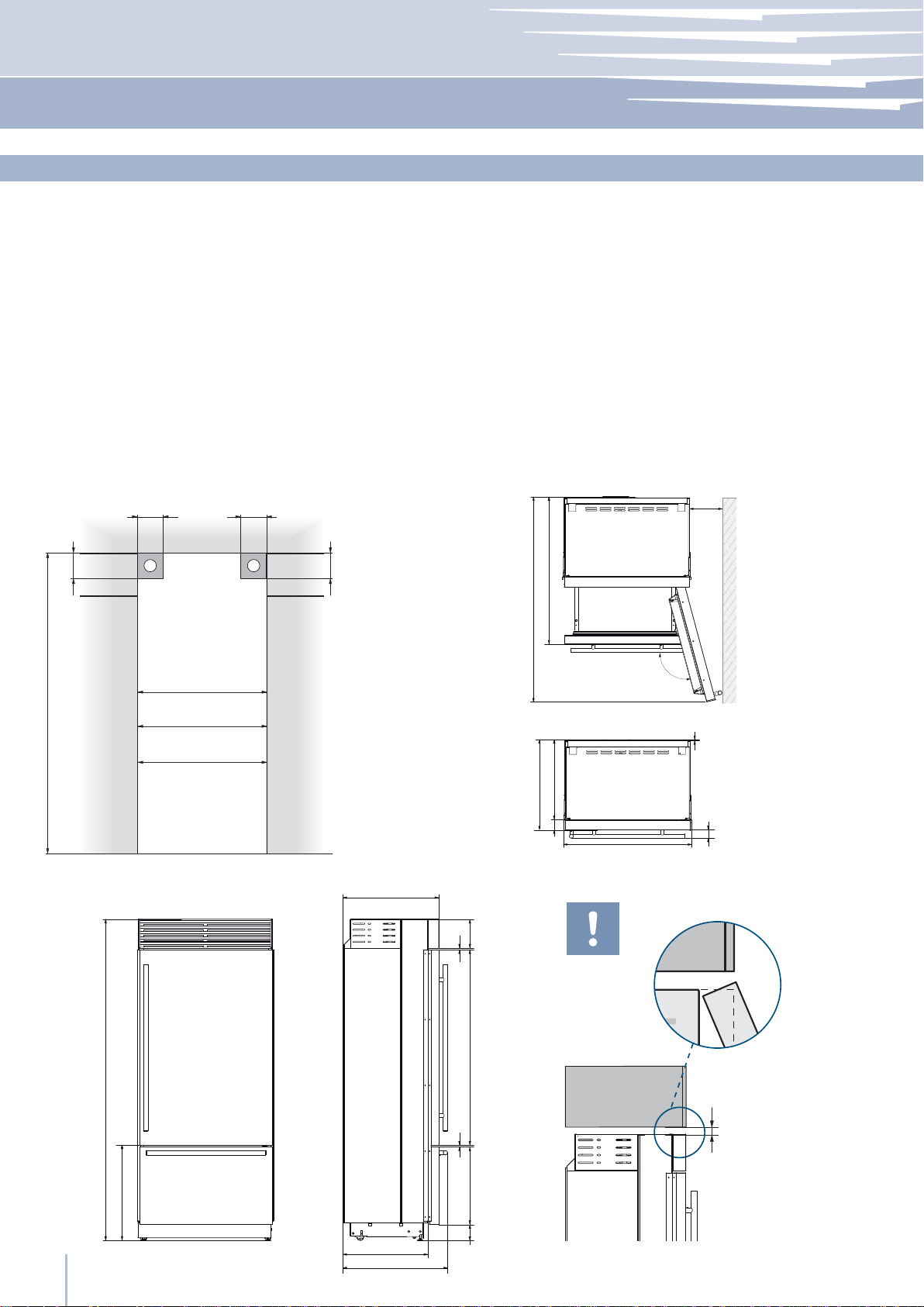
Installation niche features: X-Pro Series
A
area to be left clear for the anti-tipping brackets
Niche Height
2134 mm (84”)
Niche Width
FP36: 900 mm (35 1/2”)
FP30: 750 mm (29 5/8”)
FP24: 600 mm (23 3/4”)
Door Swing Clearance
FP36: 1470 mm (57 7/8”)
FP30: 1320 mm (52”)
FP24: 1170 mm (46”)
Door Opening Angle
105°
Width
FP36: 899 mm (35 3/8”)
FP30: 749 mm (29 1/2”)
FP24: 599 mm (23 5/8”)
Height
2120 mm (83 1/2”) + 25 mm (1”)
Depth with door
635 mm (25”)
140 (5 ½”) 140 (5 ½”)
100 (4”)
min 2134 (84”)
A A
FP36: 900 (35 ½”)
FP30: 750 (29 5⁄8”)
FP24: 600 (23 ¾”)
100 (4”)
635 (25”)
FP36: 230 (9”)
FP30: 195 (7 ¾”)
FP24: 160 (6 ¼”)
1016 (40”)
FP30: 1320 (52”)
FP24: 1170 (46”)
FP36: 1470 (57 7⁄8”)
105°
10 (3⁄8”)58 (2 ¼”)
635 (25”)
560 (22”)
FP36: 899 (35 3⁄8”)
75 (3”)
FP30: 749 (29 ½”)
FP24: 599 (23 5⁄8”)
IMPORTANT
8 (3⁄8”)
195 (7 5⁄8”)
2120 (83 ½”) +25 (1”)
613 (24 1⁄8”)+25 (1”)
www.fhiaba.com · www.thevettagroup.com
6
560 (22”)
693 (27 ¼”)
1296 (50”)
8 (3⁄8”)
485 (19 1⁄8”)
128 (5) + 25 (1”)
min 10 (3⁄8”)
Flush
Page 9
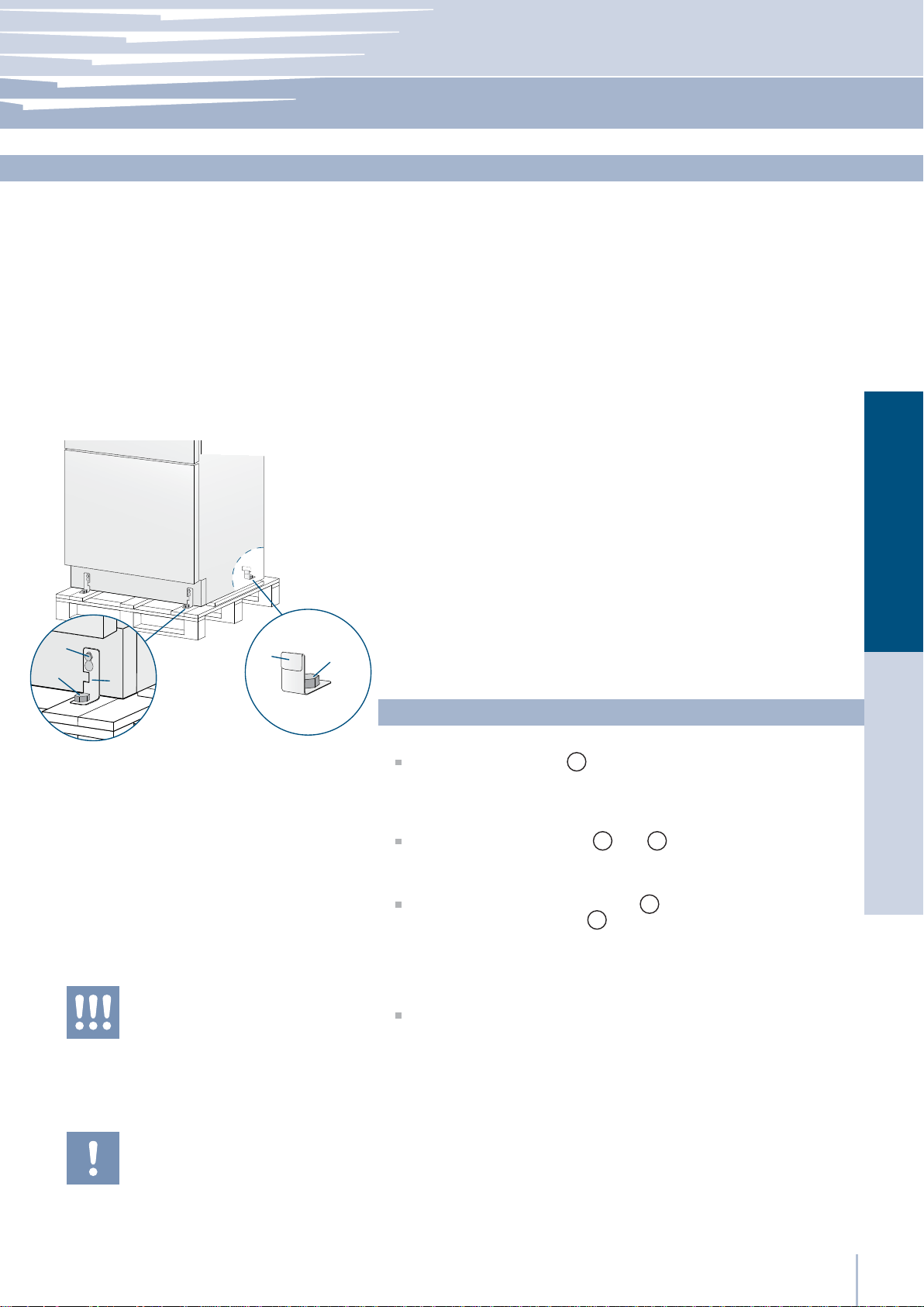
Installation Guide
Series: All
Preparing the installation
Transport to installation site
and unpacking
2
1
3
4
1
Since this is a large and heavy appliance, before transporting the appliance, check the access to the location where it will be installed
(door size, manoeuvring space in stairwells, etc.).
The appliance is attached to the base of the packaging (pallet) through
four bolts which can be removed using a 17 mm (3/4”) wrench.
It is recommended to use a manual transporting device to move the
appliance to the installation site, and only at this point to remove the
base of the packaging.
The appliance should always be transported in an erect position.
If this is not possible, transport the appliance laying on its rear side.
Once at the installation site, the appliance, which is equipped with four
wheels, can be taken off the pallet and positioned in the installation
area.
Operate as follows:
EnglishFrançais
The appliance is very heavy.
Take maximum care during handling to
avoid injury.
The appliance should always be transported in an erect position.
Avoid at all costs leaning it on its front side.
Take off the four bolts
means of a 17 mm (3/4”) open spanner.
Remove the À xing brackets 3 and 4.
To remove the front À xing bracket 3 , unscrew for one or two turns
the rear wheel adjusting bolt 2 by means of a 13 mm (1/2”) box spanner.
From the back of the unit and by means of a suitable, high duty hand
trolley, take off the appliance and place it on the Á oor .
Be very careful to avoid any damage to Á oors. Delicate Á oors should be
protected with plywood, hard cardboard or similar material panels.
securing the appliance to the pallet by
1
www.fhiaba.com · www.thevettagroup.com
7
Page 10
Series: All
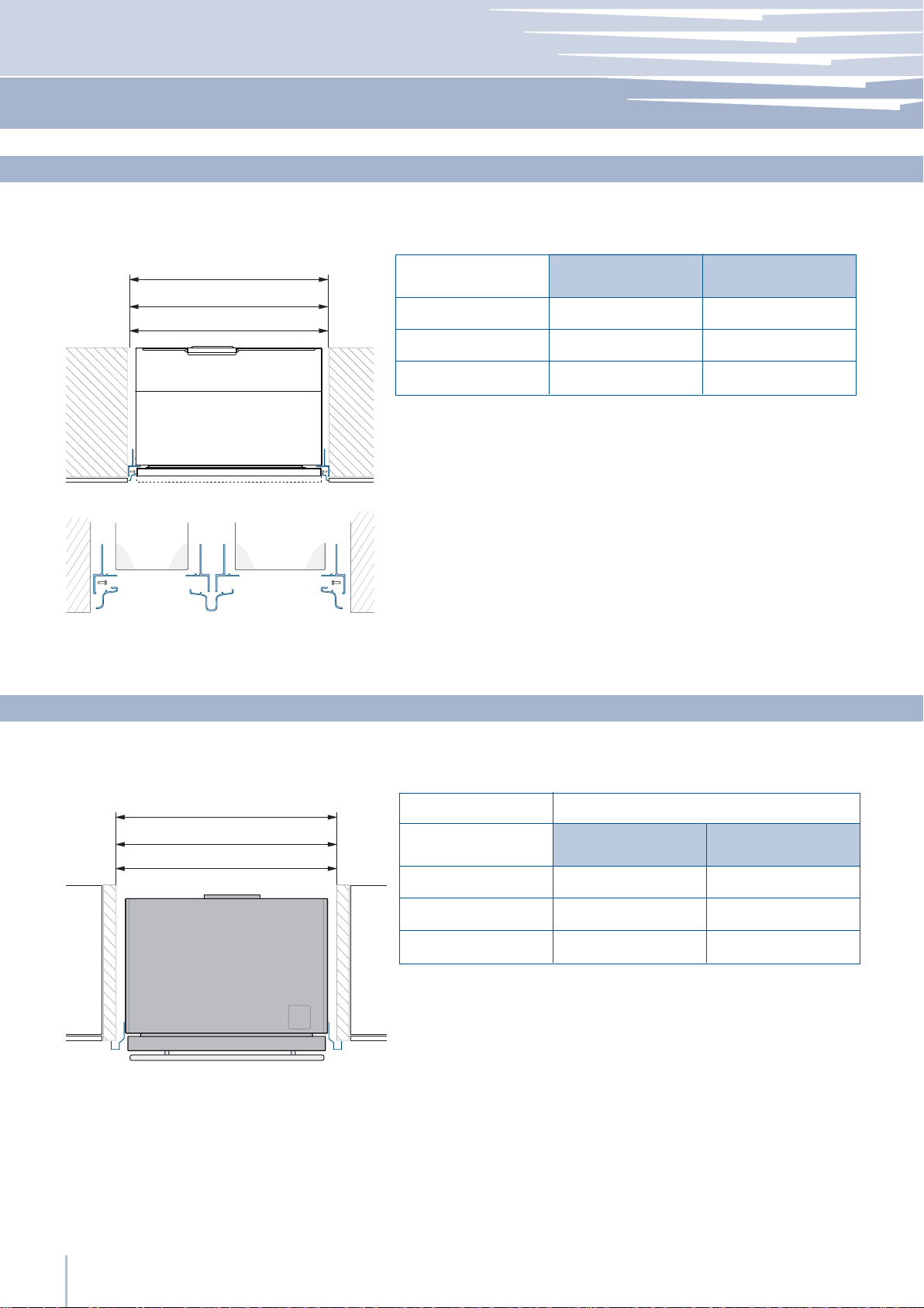
Niche Dimensions and Installation Styles: Integrated Series
FI36: 900 (35 ½”)
Series
FI30: 750 (29 5⁄8”)
FI24: 600 (23 ¾”)
AAB
A KCLITU: Lateral connection Kit
(not included - must be ordered as a
separate accessory)
B KCCITU: Central connection Kit
(not included - must be ordered as a
separate accessory)
FI36
FI30
FI24
750 (29 5/8”)
600 (23 3/4”)
Niche Dimensions and Installation Styles: StandPlus and X-Pro Series
Panels WidthNiche
897 (35 1/4”)900 (35 1/2”)
747 (29 3/8”)
597 (23 1/2”)
Stand-Proud
36: 914 (36”)
30: 762 (30”)
24: 610 (24”)
Series
36
30
24
KCLXB: Lateral connection Kit
(not included - must be ordered as a
separate accessory)
900 (35 1/2”)
750 (29 5/8”)
600 (23 3/4”)
NICHE
MAXMIN
914 (36”
762 (30”)
610 (24”)
)
www.fhiaba.com · www.thevettagroup.com
8
Page 11
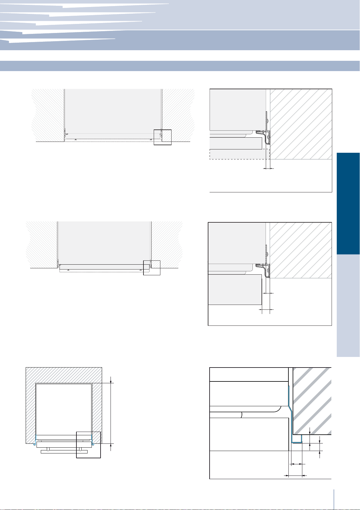
Flush installation with standard aluminum trims
Installation Guide
Series: All
Installation types
A
A KCLITU: Lateral connection Kit
(not included - must be ordered as a
separate accessory)
B KCCITU: Central connection Kit
(not included - must be ordered as a
separate accessory)
Prominent installation with standard aluminum trims
A KCLITU: Lateral connection Kit
(not included - must be ordered as a
separate accessory)
B KCCITU: Central connection Kit
(not included - must be ordered as a
separate accessory)
B
6,5 (¼”)
EnglishFrançais
A
B
6,5 (¼”)
10 (3⁄8”)
Stand-Proud (for StandPlus and X-Pro series)
Niche 610 mm (24”)
610 (24”)
KCLXB: Lateral connection Kit
(not included - must be ordered as a
separate accessory)
)
5⁄8”
15 (
)
20 (¾”)
25 (1”)
www.fhiaba.com · www.thevettagroup.com
3⁄8”
10 (
9
Page 12
Series: All
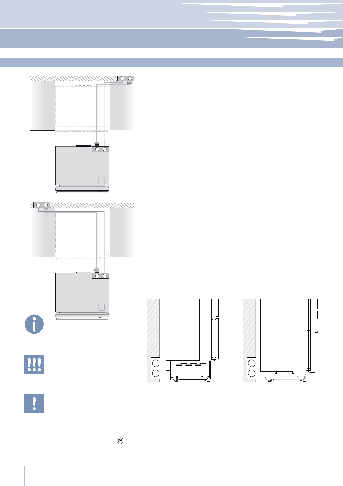
Electrical and Water connection
EW
E W
E W
The appliances are delivered from the factory for operation at 110V120V AC - 60Hz (US and Canada).
They are provided with a suitable supply cable and plug to be connected to an appropriate 15A socket (US and Canada) provided
with an effective grounding.
A circuit breaker should also be installed and should be easily accessible so that it can be easily switched off before performing any
installation or maintenance.
To connect to the water supply system (for appliances equipped with
ice makers) a 1/4” waterline with accessible shut-off valve must be
supplied.
The appliance is provided with a water adapter elbow which is suitable for high water pressure and complies the Food Regulations.
The water À lter cartridge, which is provided with the appliance,
should be installed according to the accompanying instructions. Use
only the new adapter which is supplied with the appliance. The solenoid connection on the appliance is 3/4” diameter but is metric
threaded. A standard garden hose threaded connector such as a
braided stainless hose found at typical hardware stores will strip or
damage the solenoid threads. Use only the supplied 1/4” quick connect elbow adapter for connecting a 1/4” copper or polyethylene
source water line to the appliance.
EW
The Built-in Fhiaba À lter cannot make it safe
to drink any water which is not suitable for
human consumption.
The appliance should be connected only to
a drinkable water supply system.
Electrical cord length: 2500 mm (98 3/8”)
Water connection line length: 2500 mm (98 3/8”)
Electrical and water supply behind the unit
Integrated Series StandPlus and X-Pro Series
E
W
E
W
Do not use extension cords or adapters.
Once the appliance is fully installed, connected to the water supply (if applicable) and
operational, in the event that the water supply must be turned off,(touch the button
control panel to switch it off) before the main
water is shut off to prevent the appliance from
entering a ‘NO WATER IN’ alarm state.
www.fhiaba.com · www.thevettagroup.com
10
on
Page 13
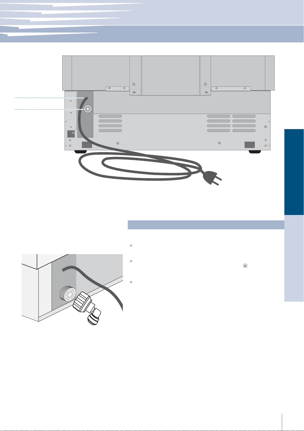
Electrical connection
Water connection
Installation Guide
Series: Integrated
Back of appliance
Operate as follows:
Unwind the electric cable and connect it directly to the wall socket.
Make sure the appliance is in the Stand-by condition and that all
lights are off; should it be not so press the Unit button to switch it off.
Push the 1/4” source waterline fully into the elbow connector then
thread the elbow adapter to the solenoid at the back of the appliance.
Firmly tighten with À ngers - a tool / wrench should not be needed to
make a proper seal. Turn on the water and ensure all connections
are not leaking prior to pushing the unit into the niche.
EnglishFrançais
www.fhiaba.com · www.thevettagroup.com
11
Page 14
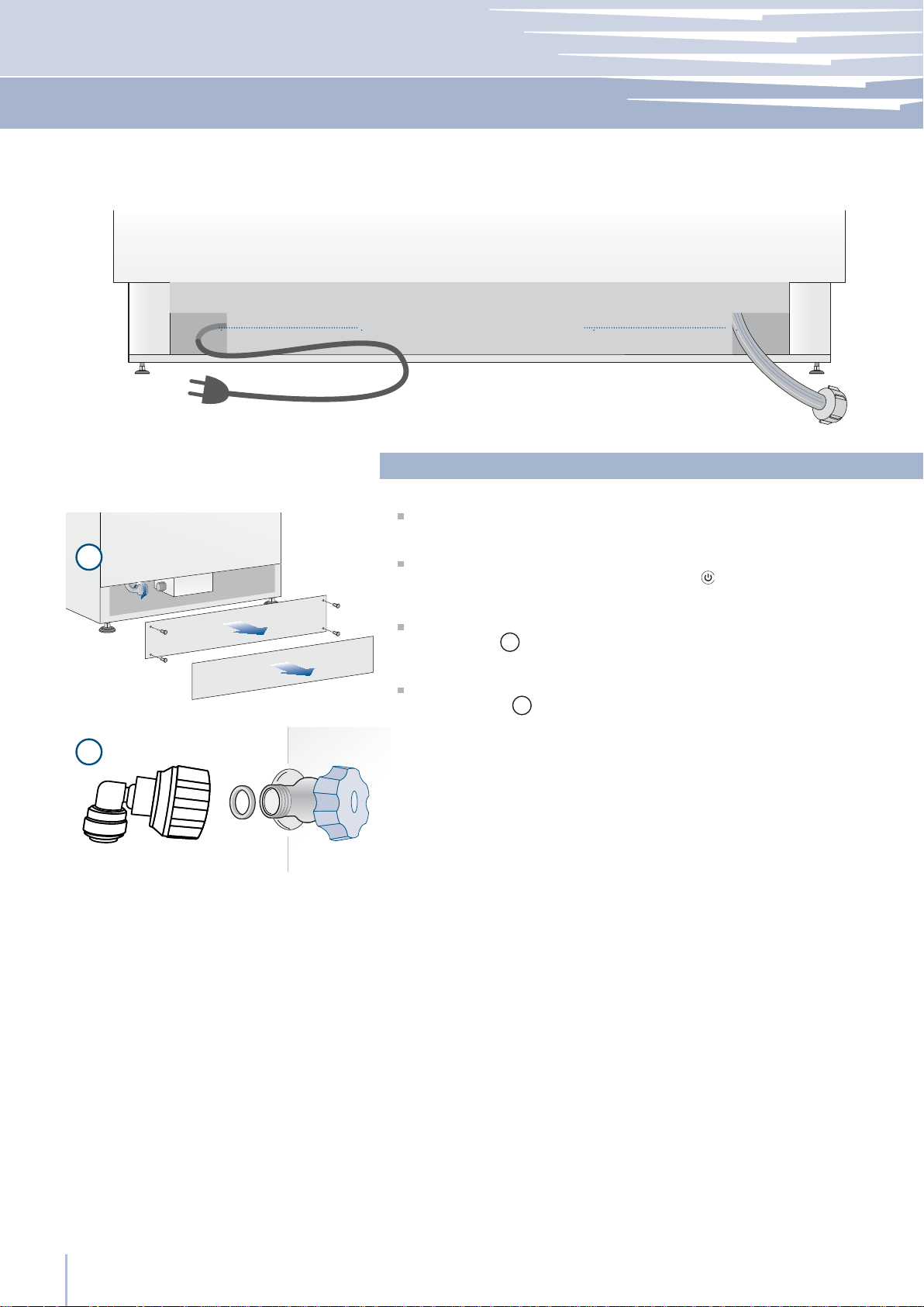
Series: StandPlus/X-Pro
Back of appliance
Water connectionElectrical connection
Operate as follows:
Front of appliance
1
2
Unwind the electric cable and connect it directly to the wall socket.
Make sure the appliance is in the Stand-by condition and that all ights
are off; should it be not so press the Unit button to switch it off.
Connect the water line to the threaded connection at the base of the
unit, as in À gure 1.
Fit the other end of the hose to the water tap, use the gaskets provided
in the Owner’s Kit 2.
Firmly tighten with À ngers - a tool / wrench should not be needed to
make a proper seal. Turn on the water and ensure all connections are
not leaking prior to pushing the unit into the niche.
www.fhiaba.com · www.thevettagroup.com
12
Page 15
Installation Guide
Series: All
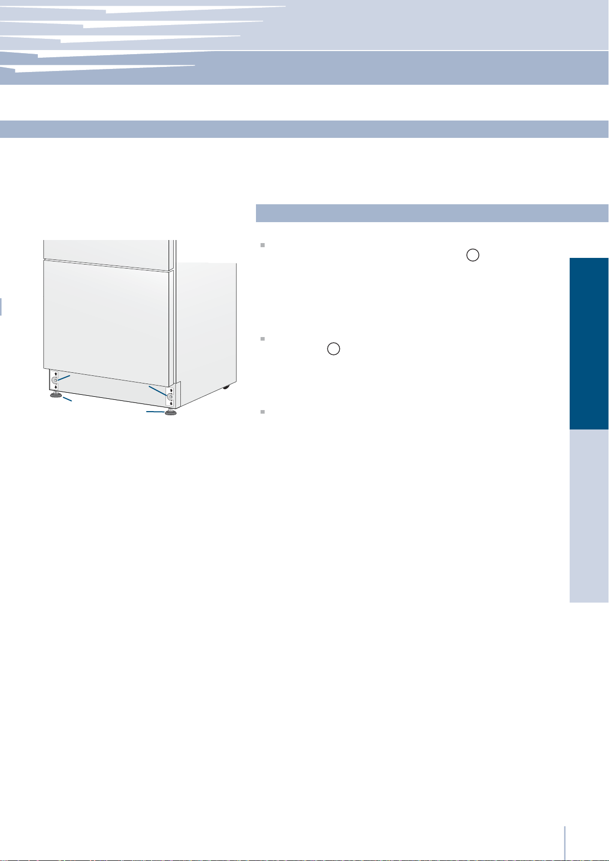
Levelling
Adjust the appliance level by means of the front levelling feet
and the rear adjustable wheels.
Operate as follows:
After removing the bottom plinth or grille (it is kept in position by
magnets), adjust the height of the levelling feet 1 by means of a 17
mm (3/4”) open spanner.
2
1
2
1
Then adjust the height of the rear wheels by turning the front
adjusting bolts 2 clockwise or anticlockwise as it may be required.
EnglishFrançais
Remount the bottom plinth or grille.
www.fhiaba.com · www.thevettagroup.com
13
Page 16
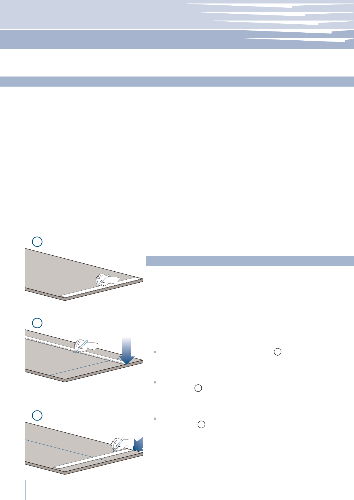
Series: Integrated
Decorative door and bottom-drawer panels layout
The dimensions of the panels are indicated in the table and drawings on pages 16-19.
Nevertheless, according to the requirements for aligning with other
kitchen structures, the door panel can be higher than the upper
edge of the refrigerator door, and the drawer panel can be lower
than the edge of the drawer.
The panels must be mounted using special braces which attach
to adjustable devices provided on the door and drawer and with
brackets that anchor and adjust the panel’s vertical direction.
Braces, brackets and fixing screws are provided with the appliance
and must be applied to the panel as indicated.
1
Operate as follows:
To prepare the panels to be mounted on the appliance, follow
these steps, working on the back of the panel.
2
Door Panel
Trace, a line dividing the panel width in half 1.
Starting form the Bottom edge of the panel, mark the positioning
of the brackets 2.
3
www.fhiaba.com · www.thevettagroup.com
14
Following the corresponding table, mark the external and then
the internal hole
.
3
Page 17
Installation Guide
Series: Integrated
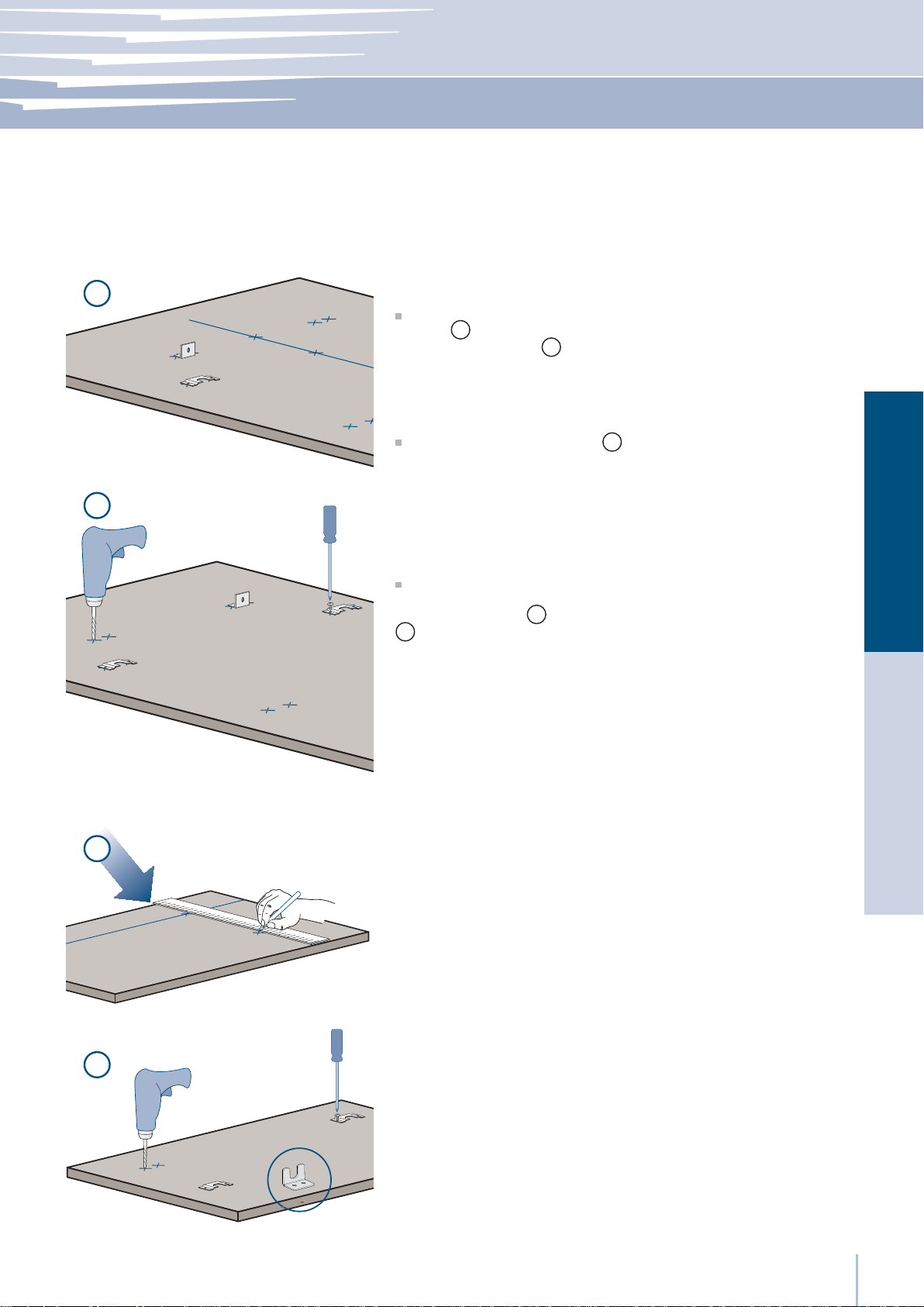
4
Position the brackets on each set of marks to make sure they are
aligned 4, then drill holes through the panel (pay close attention to
the panel’s thickness)5.
Screw the brackets in place 6.
5
Drawer Panel
When preparing the Drawer Panel, follow the same instructions as
per the door panel, but make sure measurements are taken starting
from the top edge 7. The support bracket faces the opposite way
(note imgs 4 and 8).
8
EnglishFrançais
7
8
www.fhiaba.com · www.thevettagroup.com
15
Page 18
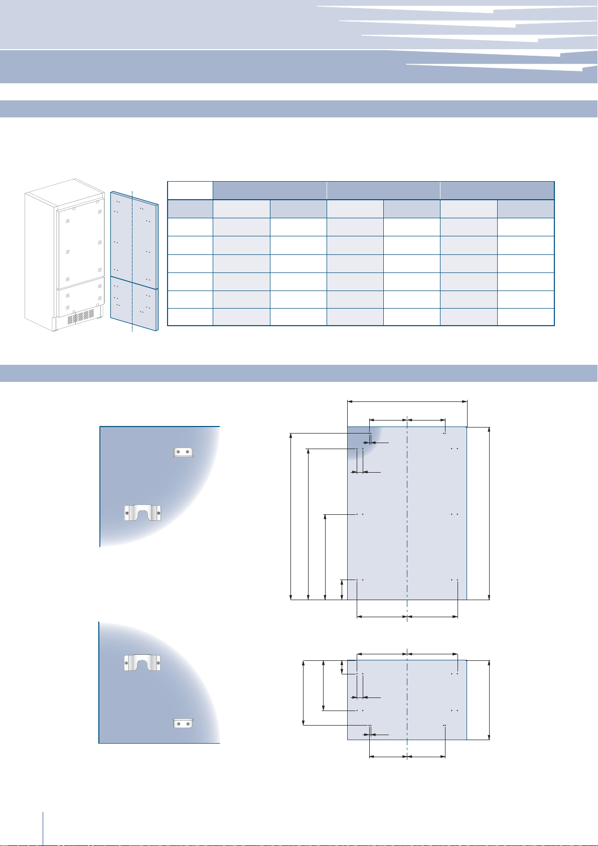
Series: Integrated
Decorative panels layout for Fridge with one Bottom-Drawer
Series 36
Hinge Left Hinge Left Hinge Left
A
B
C
D
E
897 (35 ¼”) 897 (35 ¼”) 747 (29 3⁄8”) 747 (29 3⁄8”) 597 (23 ½”)
355.5 (14”)
418 (16
354.5 (14”) 354.5 (14”) 279.5 (11”) 279.5 (11”) 203.5(8”)
Hinge Right Hinge Right Hinge Right
261 (10 ¼”)
355.5 (14”)
½”)
386 (15
418 (16
¼”)
½”)
Series 30 Series 24
279 (11”)
187 (7 3⁄8”)
343 (13
311 (12
½”)
¼”)
187 (7
279 (11”)
311 (12
343 (13
3⁄8”)
¼”)
½”)
205 (8
111 (4
276.5 (10 7⁄8”)
236.5 (9
1⁄8”)
3⁄8”)
3⁄8”)
597 (23 ½”)
111 (4
3⁄8”)
1⁄8”)261 (10 ¼”)
205 (8
236.5 (9 3⁄8”)
276.5 (10 7⁄8”)386 (15 ¼”)
203.5(8”)F / G
Holes positions
A
B C
13 (½”)
3⁄8”)
34 (1
¾”)
1285 (50 5⁄8”)
1163 (45
507.5 (20”)
¼”)
660 (26”)
157 (6
1⁄8”)
100 (4”)
382 (15
D E
D E
3⁄8”)
34 (1
½”)
13 (
F G
¾”)max 635 (25”)
min 1390 (54
www.fhiaba.com · www.thevettagroup.com
16
Page 19
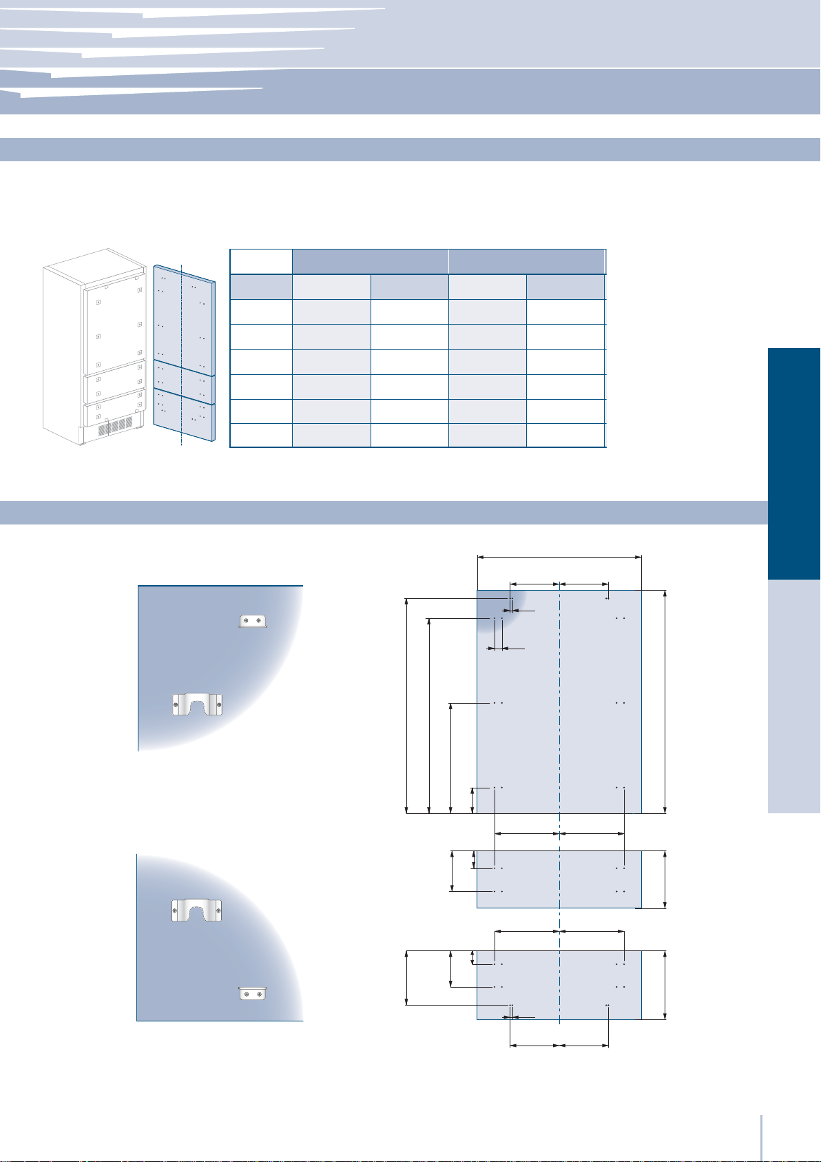
Installation Guide
Series: Integrated
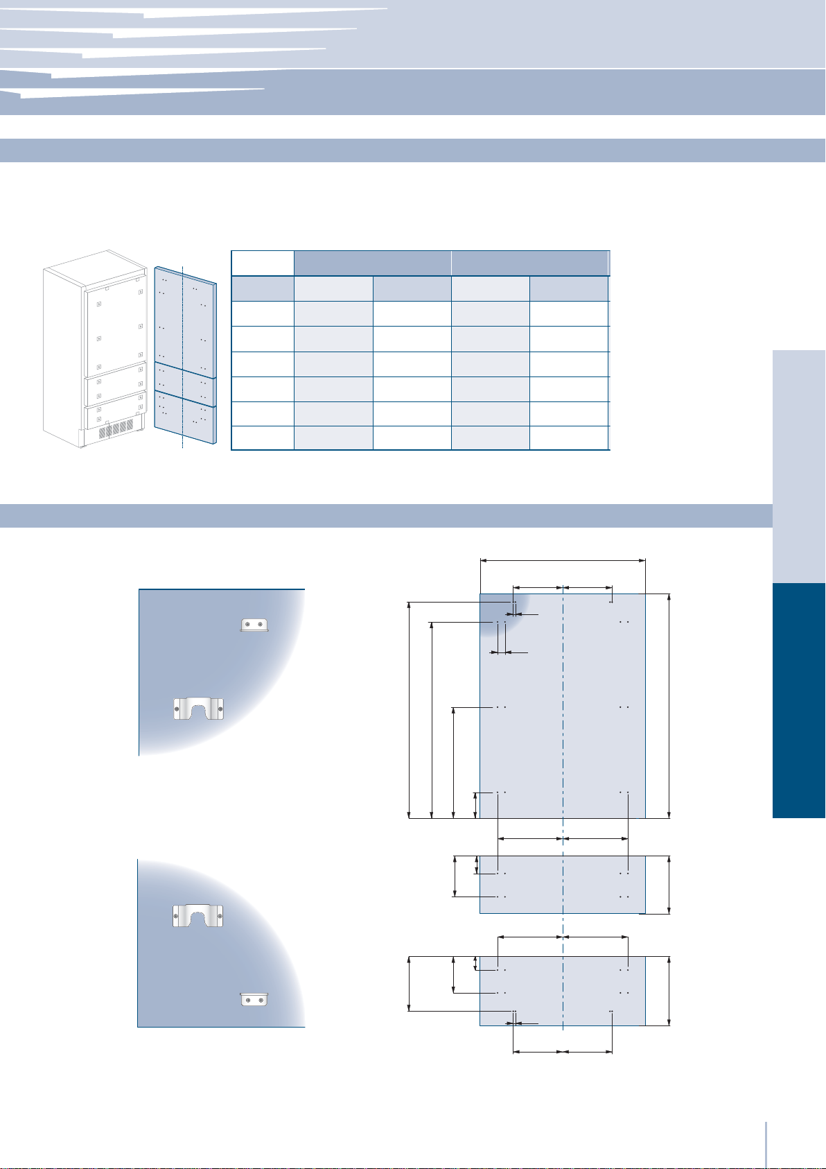
Decorative panels layout for Fridge with two Bottom-Drawers
A
B
C
D
E
F / G
Series 36
Hinge Left Hinge Left
897 (35 ¼”) 897 (35 ¼”) 747 (29 3⁄8”) 747 (29 3⁄8”)
355.5 (14”)
261 (10
418 (16
354.5 (14”) 354.5 (14”) 279.5 (11”) 279.5 (11”)
Hinge Right Hinge Right
261 (10 ¼”)
¼”)
½”)
355.5 (14”)
¼”)
386 (15
418 (16
½”)
279 (11”)
187 (7 3⁄8”)
343 (13
311 (12
Series 30
187 (7
279 (11”)
½”)
311 (12
343 (13
¼”)
Holes positions
B C
½”)
13 (
34 (1
3⁄8”)
3⁄8”)
¼”)
½”)386 (15 ¼”)
A
EnglishFrançais
5⁄8”)
1⁄8”)
1160 (45
1044 (41
½”)
268 (10
½”)
292,5 (11
¼”)
183 (7
5⁄8”)
600 (23
5⁄8”) 157 (6 ¼”)
66 (2
7⁄8”)
73 (2
min 1265 (49 ¾”)
D E
¼”)max 415 (16 3⁄8”)
337 (13
D E
13 (½”)
F G
www.fhiaba.com · www.thevettagroup.com
17
Page 20
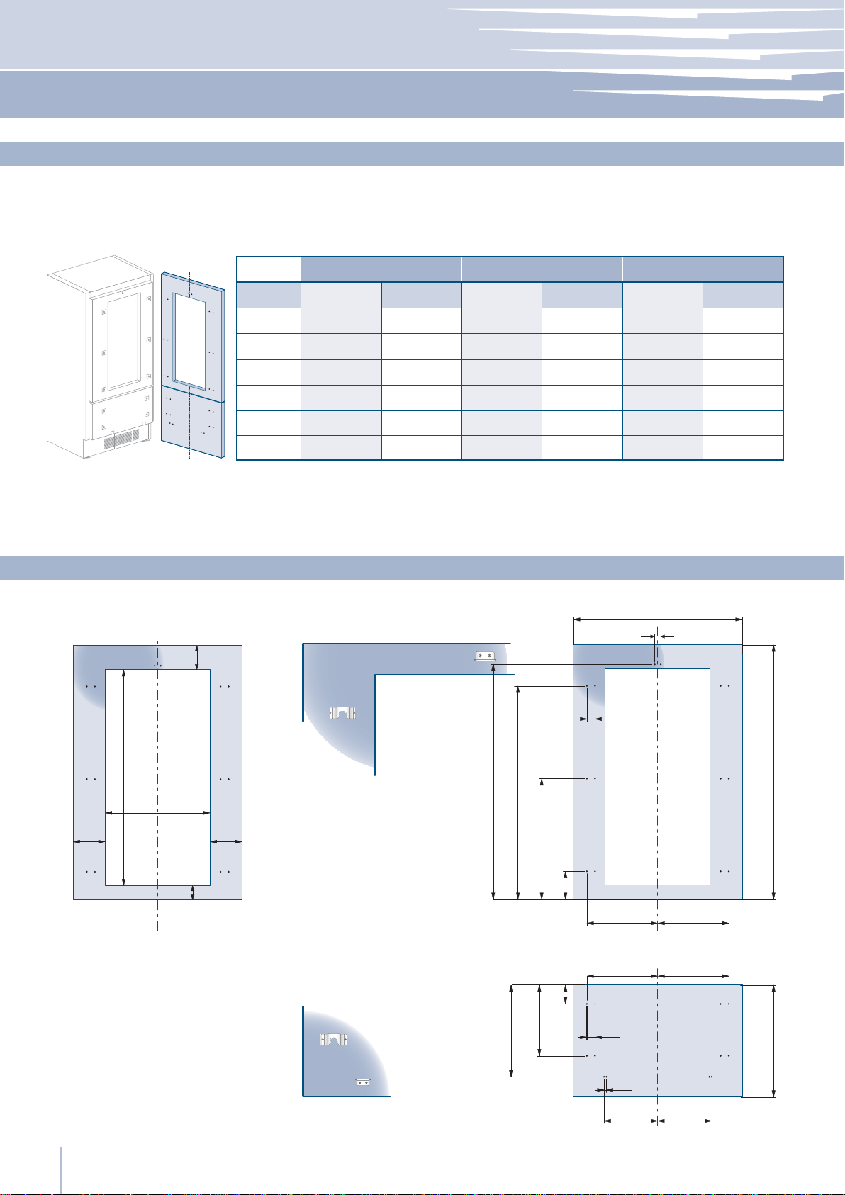
Series: Integrated
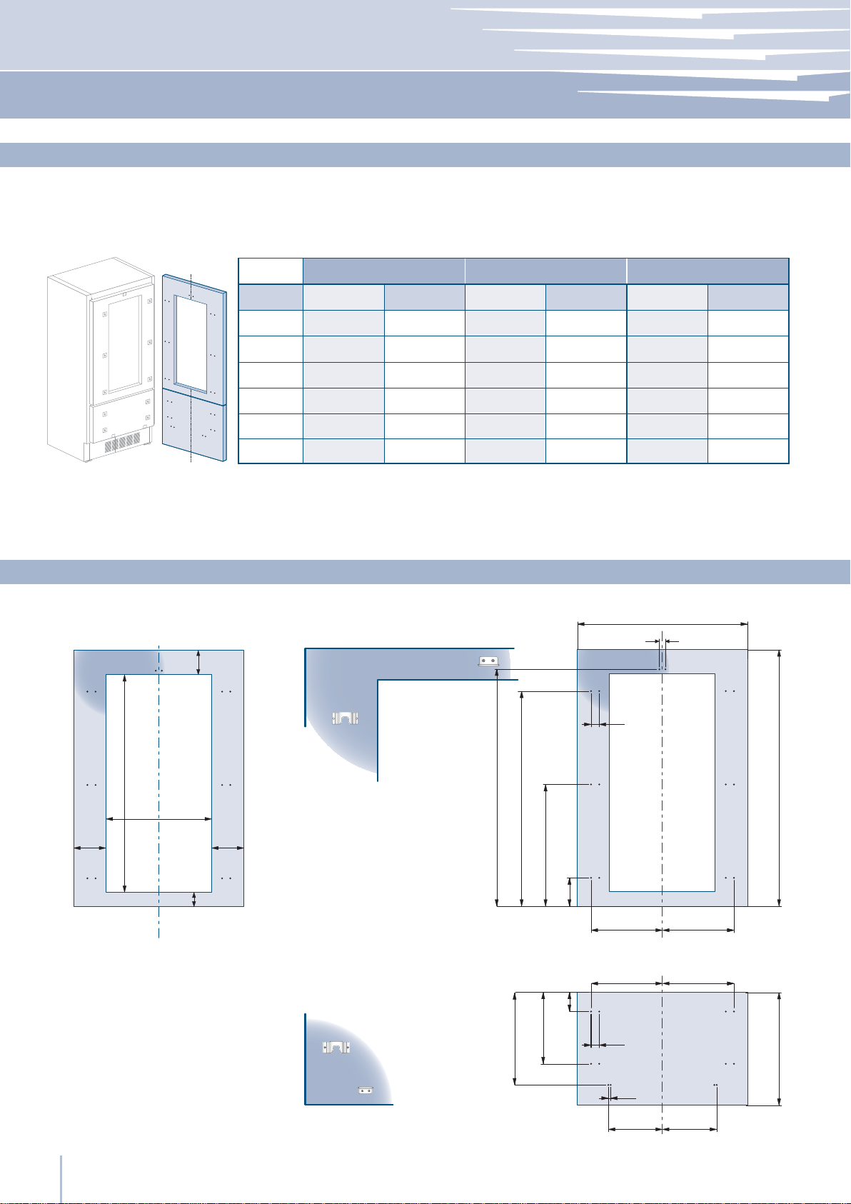
Decorative panels layout for Fridge with glass door and one Bottom-Drawer
F / G
<200 (7 7⁄8”)
Series 36
Hinge Left Hinge Left Hinge Left
A
D
E
H
I
897 (35 ¼”) 897 (35 ¼”)
418 (16
354.5 (14”) 354.5 (14”) 279.5 (11”) 279.5 (11”) 203,5(8”) 203,5(8”)
412 (16
Hinge Right Hinge Right Hinge Right
½”)
¼”)
386 (15
418 (16
380 (15”)
412 (16
¼”)
½”)
¼”)
Series 30
747 (29 3⁄8”) 747 (29 3⁄8”) 597 (23 ½”) 597 (23 ½”)
½”)
¼”)
311 (12 ¼”)
343 (13 ½”)
305 (12”)
337 (13
¼”)
270.5 (10 5⁄8”)
343 (13
311 (12 ¼”)
337 (13
305 (12”)
Series 24
276.5 (10
236.5 (9 3⁄8”)
230.5 (9
7⁄8”)
1⁄8”)
236.5 (9
276.5 (10 7⁄8”)386 (15 ¼”)
230.5 (9 1⁄8”)
270.5 (10
3⁄8”)
5⁄8”)380 (15”)
Holes positionsDoor window dimensions
A
6,5 (
¼”)
6,5 (¼”)
135 (5
1075 (42 3⁄8”)
36: 627 (24 ¾”)
30: 477 (18
24: 327 (12
3⁄8”)
¾”)
7⁄8”)
135 (5
115 (4
3⁄8”)
½”)
3⁄8”)
1286 (50 5⁄8”)
1152,5 (45
507,5 (20”)
5⁄8”)
7⁄8”)
650,5 (25
148,5 (5
1⁄8”)
100 (4”)
382 (15
34 (1
3⁄8”)
H I
D E
3⁄8”)
34 (1
13 (
½”)
F G
min 1390 (54 ¾”)
max 635 (25”)
www.fhiaba.com · www.thevettagroup.com
18
Page 21
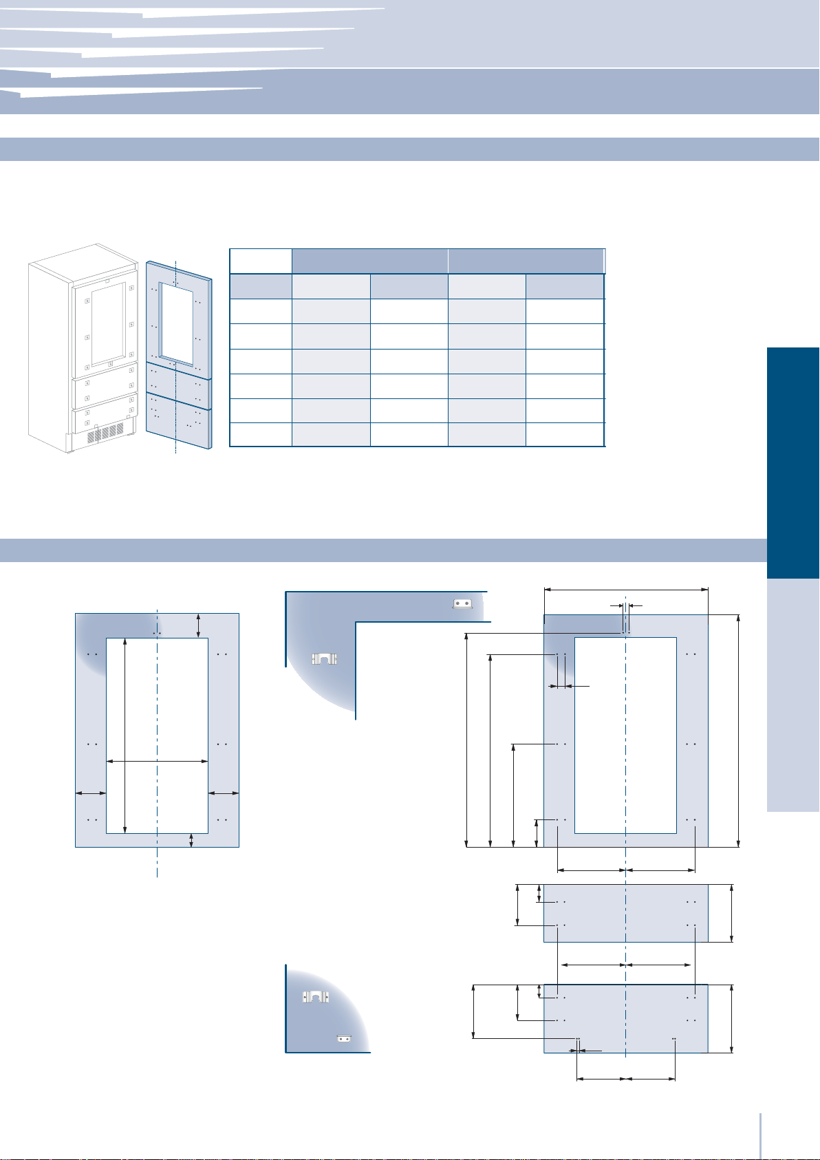
Installation Guide
Series: Integrated
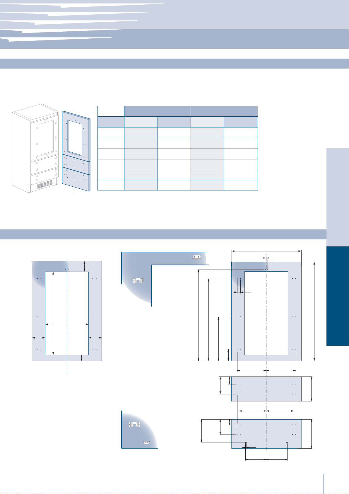
Decorative panels layout for Fridge with glass door and two Bottom-Drawers
A
D
E
F / G
H
I
<200 (7 7⁄8”)
Series 36
Hinge Left Hinge Left
897 (35 ¼”) 897 (35 ¼”)
418 (16
386 (15
354.5 (14”) 354.5 (14”) 279.5 (11”) 279.5 (11”)
412 (16
380 (15”)
Hinge Right Hinge Right
½”)
¼”)
¼”)
386 (15
418 (16
380 (15”)
412 (16
¼”)
½”)
¼”)
Series 30
747 (29 3⁄8”) 747 (29 3⁄8”)
½”)
¼”)
311 (12 ¼”)
343 (13 ½”)
305 (12”)
337 (13
¼”)
343 (13
311 (12 ¼”)
337 (13
305 (12”)
Holes positionsDoor window dimensions
6,5 (
¼”)
EnglishFrançais
A
6,5 (¼”)
135 (5
3⁄8”)
950 (37 3⁄8”)
36: 627 (24 ¾”)
30: 477 (18 ¾”)
24: 327 (12
7⁄8”)
135 (5
115 (4
3⁄8”)
½”)
3⁄8”)
1161 (45 ¾”)
1026,7 (40
½”)
292,5 (11
1⁄8”)
7⁄8”)
588 (23
149,5 (5
5⁄8”)
66 (2
268 (10 ½”)
7⁄8”)
73 (2
¼”)
183 (7
3⁄8”)
34 (1
H I
D E
13 (½”)
F G
min 1265 (49 ¾”)
¼”)
337 (13
3⁄8”)
max 415 (16
www.fhiaba.com · www.thevettagroup.com
19
Page 22
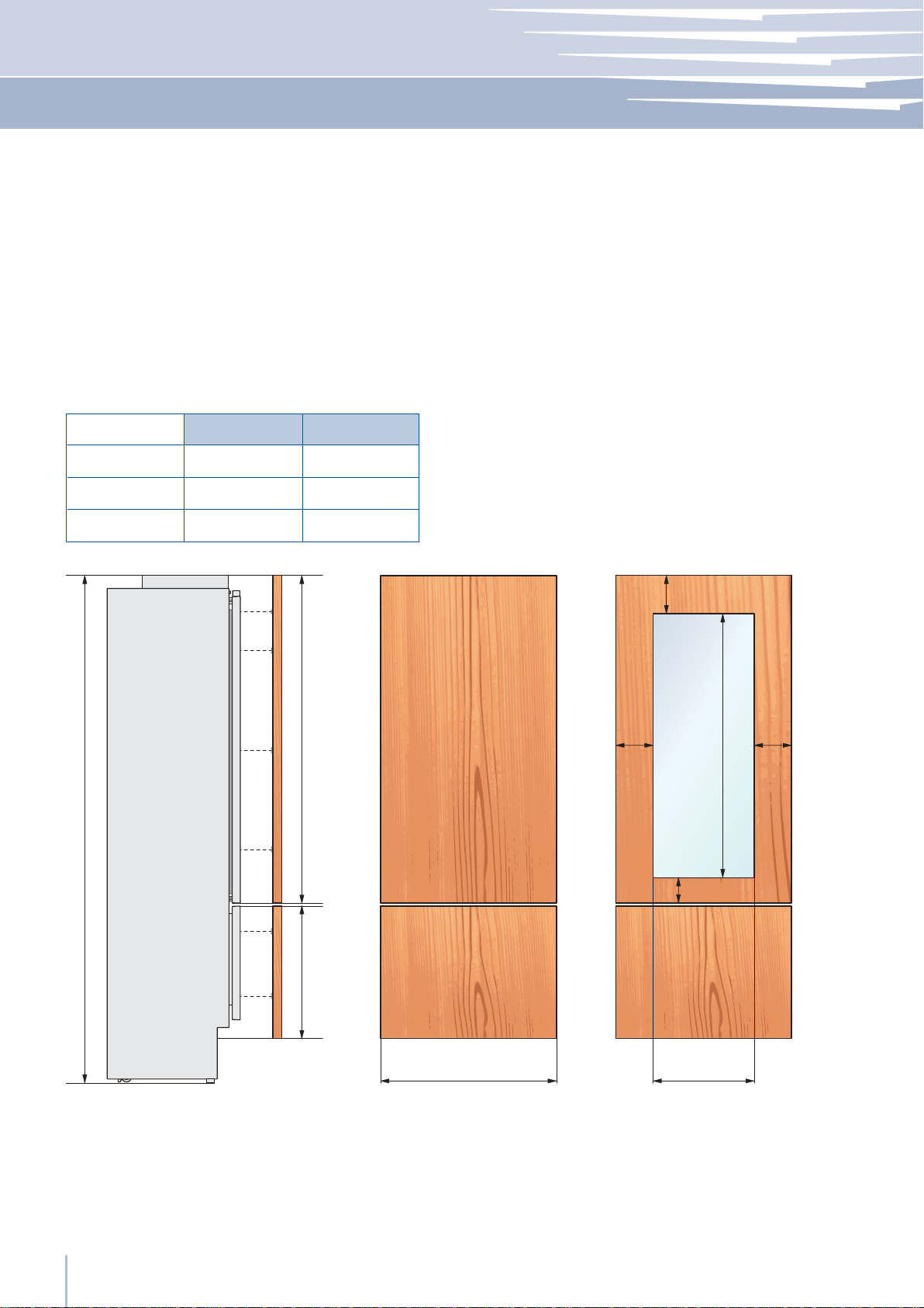
Series: Integrated
Panels Dimensions Single Bottom - Drawer
Panels can have thickness ranging between 18 mm (3/4”) and 28 mm (1-1/8“).
Door panels can have a maximum weight 23 kg (51 lbs) and drawer panels may be a maximum weight of 11kg (25
lbs)
Exceeding these weights could void your warranty for any service issues which can be attributed to overweight
panels.
The hinging mechanism on Fhiaba appliances is considered to be `Zero-clearance`. The door and drawer widths
specified below assume the minimum niche width is being used and a 3.5mm (1/8”) reveal is desired around the panels.
Adjust your panel dimensions accordingly to your own design criteria considering your niche width and your reveal.
Minimum reveal / gap should not be less than 1.5mm (1/16”).
Series
FI36
FI30
FI24
Door/Drawer Width
Door Cutout Width
A
B
627 (24 3/4”)897 (35 1/4”)
477 (18 3/4”)747 (29 3/8”)
327 (12 7/8”)597 (23 1/2”)
min 200 (7 7⁄8”)
135
(5 3⁄8”)
1390 (54 ¾”)
1075 (42 3⁄8”)
135
(5 3⁄8”)
2121 (83 ½") + 25 (1")
Example:
84” niche height
36” niche width
4” toe kick height
1/8” gap desired all around
www.fhiaba.com · www.thevettagroup.com
20
3 (1⁄8”)
max 635 (25”)
min 540 (21 ¼”)
115 (4 ½”)
A B
Door panel:
Width: 35-3/4”
Height: 54-3/4”
Drawer panel:
Width: 35-3/4”
Height: 84”-1/8”-54-3/4”-1/8”-4”=25”
If you want a 6” toe kick height then your bottom drawer
panel height would be 23”
Page 23

Installation Guide
Series: Integrated
Panels Dimensions Two Bottom - Drawers
Panels can have thickness ranging between 18 mm (3/4”) and 28 mm (1-1/8“).
Door panels can have a maximum weight 23 kg (51 lbs) and drawer panels may be a maximum weight of 11kg (25
lbs)
Exceeding these weights could void your warranty for any service issues which can be attributed to overweight
panels.
The hinging mechanism on Fhiaba appliances is considered to be `Zero-clearance`. The door and drawer widths
specified below assume the minimum niche width is being used and a 3.5mm (1/8”) reveal is desired around the panels.
Adjust your panel dimensions accordingly to your own design criteria considering your niche width and your reveal.
Minimum reveal / gap should not be less than 1.5mm (1/16”).
Series
FI36
FI30
2121 (83 ½") + 25 (1")
Door/Drawer Width
897 (35 1/4”)
747 (29 3/8”)
Door Cutout Width
A
627 (24 3/4”)
477 (18 3/4”)
3 (1⁄8”)
B
EnglishFrançais
min 200 (7 7⁄8”)
135
(5 3⁄8”)
115 (4 ½”)
135
(5 3⁄8”)
950 (37 3⁄8”)
Example:
84” niche height
36” niche width
4” toe kick height
1/8” gap desired all around
337 (13 ¼”) 1265 (49 ¾”)
3 (1⁄8”)
min 325 (12 ¾”)
max 415 (16 3⁄8”)
A B
Door panel:
Width: 35-3/4”
Height: 54-3/4”
Drawer panel:
Width: 35-3/4”
Height: 84”-1/8”-54-3/4”-1/8”-4”=25”
If you want a 6” toe kick height then your bottom drawer
panel height would be 23”
www.fhiaba.com · www.thevettagroup.com
21
Page 24
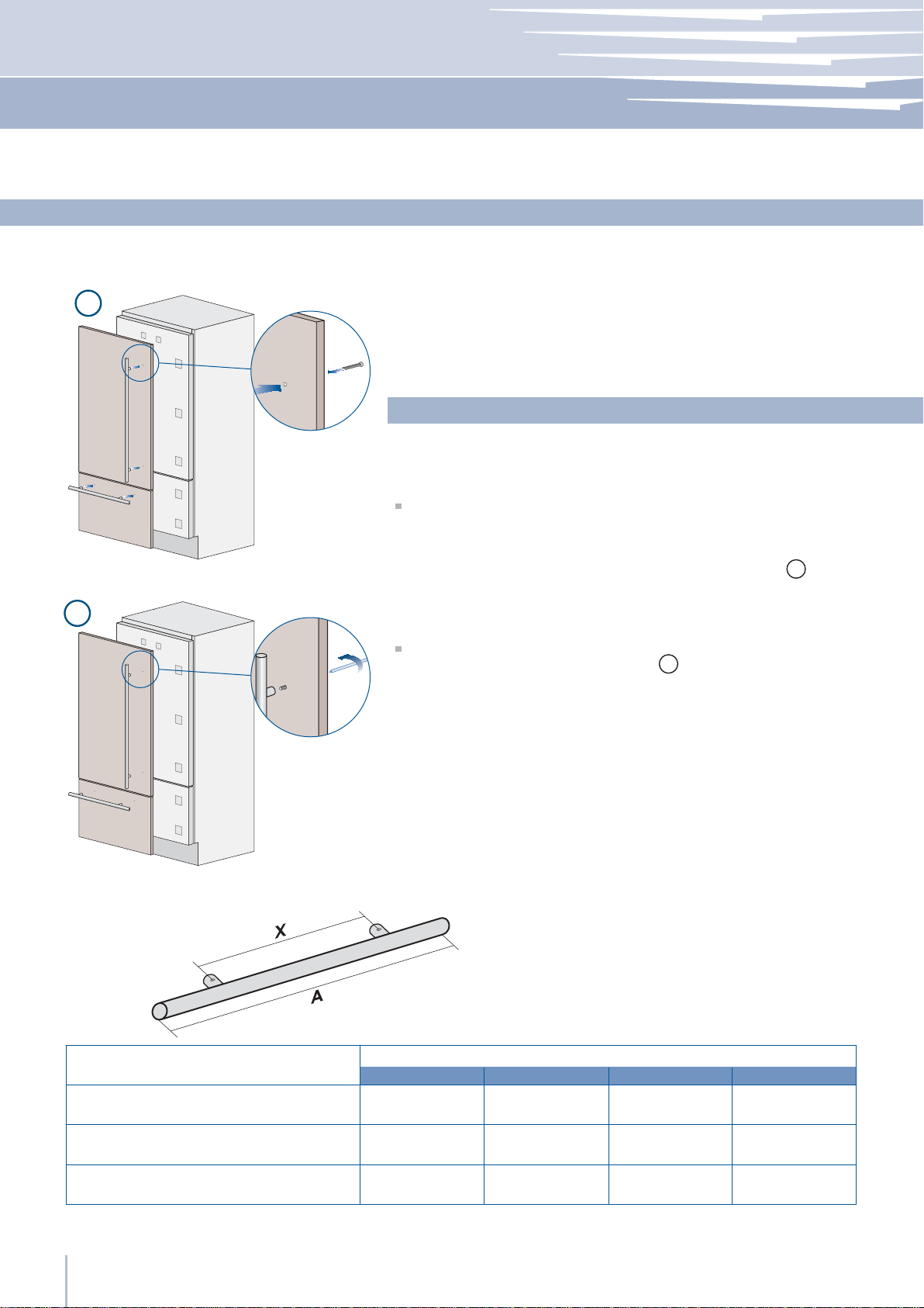
Series: Integrated
Mounting the handles on Integrated units
1
Handles will have to be mounted on the panels before they are applied to the fridge.
Operate as follows:
Drill two holes of 5 mm (1/4 “) on the rear side panels, insert the supplied screws to the distance indicated in the
the table below. To center the vertical handle (code HV) to
the center of the door , split into two the height of the panel and make
a hole at -45 cm (-17 3/4 “) and one at +45 cm (+17 3/4”) 1.
2
Place the handle on top of the holes and insert the screws through
the panel and into the handle support 2.
Distance between
Length A
À xing points
Series
X
1104 mm
(43 1/2”)
900 mm
(35 1/2”)
899
749
599
Handle product code
HO8HV
794 mm
(31 1/4”)
480 mm
(18 7/8”)
899
HO7
644 mm
(25 3/8”)
490 mm
(19 1/4”)
749
HO5
494 mm
(19 5/8”)
340 mm
(13 3/8”)
599
www.fhiaba.com · www.thevettagroup.com
22
Page 25
Installation Guide
Series: Integrated
Mounting panels to the door and the drawer of Integrated units
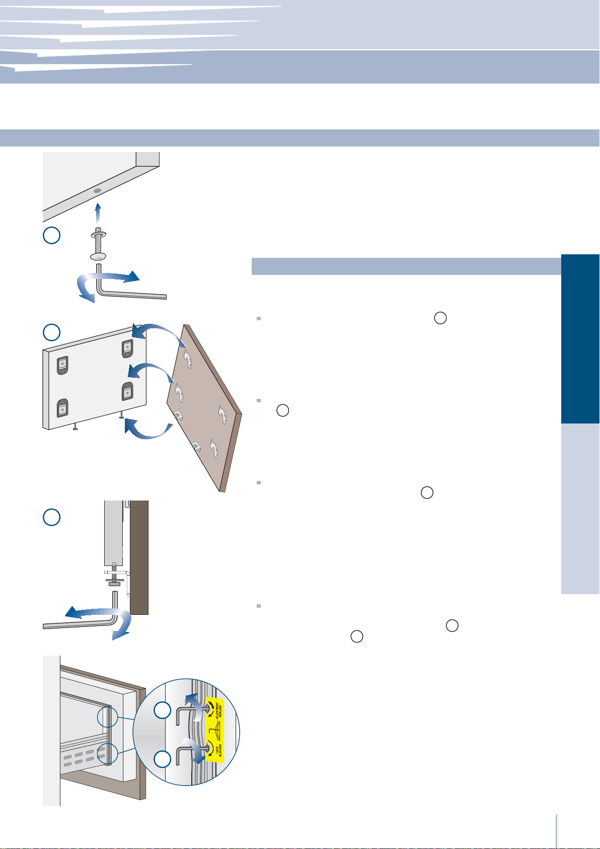
Once all brackets and small brackets have been applied to the panels, you can begin installing the bottom drawer.
1
Operate as follows:
Partially tighten the screw to the À xing 1.
2
EnglishFrançais
Hook the bottom drawer panel starting from the À xings on the bot-
tom 2.
It is now possible to align panels to adjacent cabinets in height
using the lower alignment brackets, 3 tightening or untightening
the screws into position as needed. With the screw slighty tightened,
3
move the panel sideways to align it to the other panels on the unit or
other adjacent structures.
Depth alignment: working from the inside of the drawer, after lifting up the magnetic seal, adjust the panel position so it is closer to or
further away from the door using the holes
panel using the holes
.
5
and then secure the
4
4
5
www.fhiaba.com · www.thevettagroup.com
23
Page 26
Series: Integrated
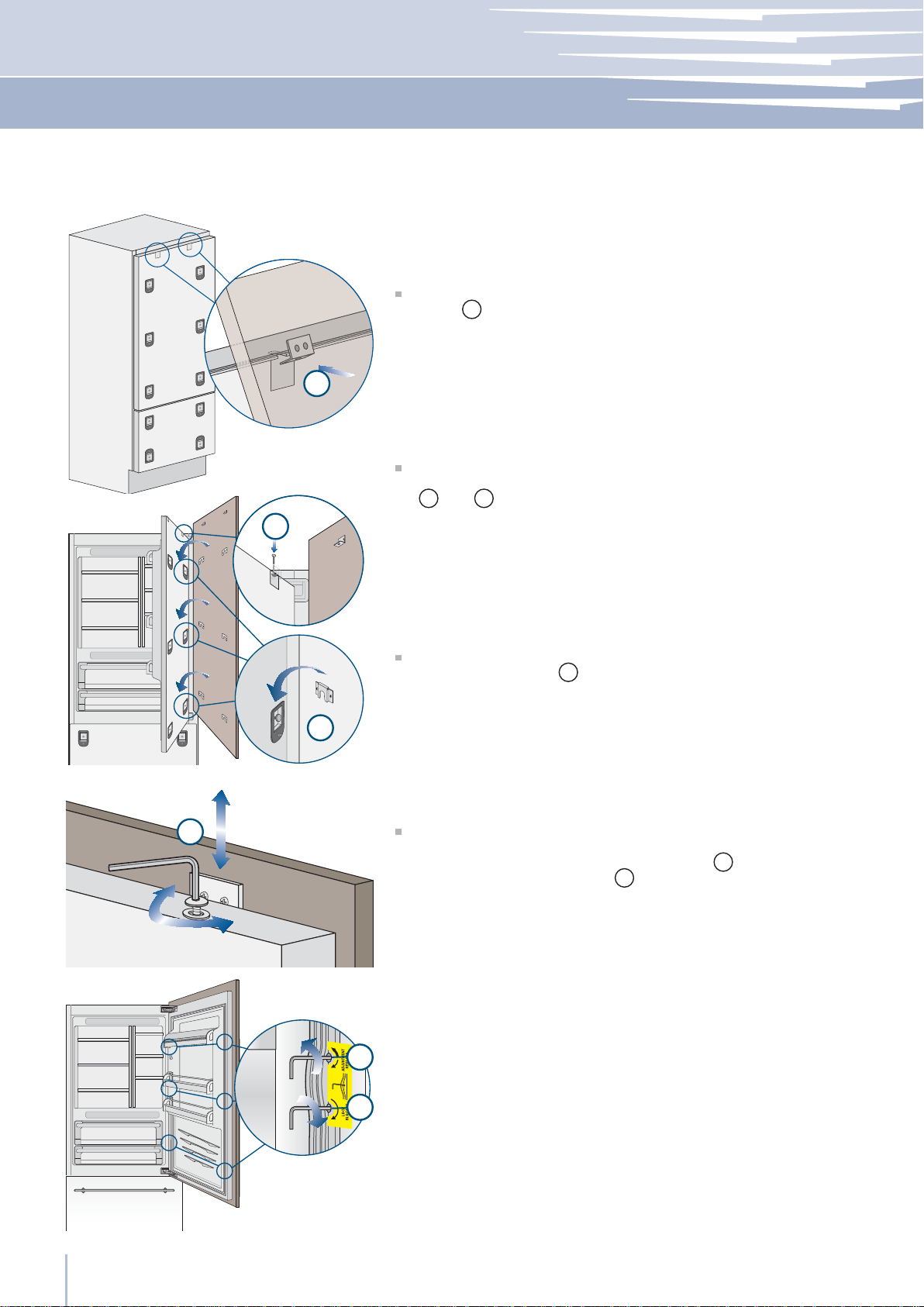
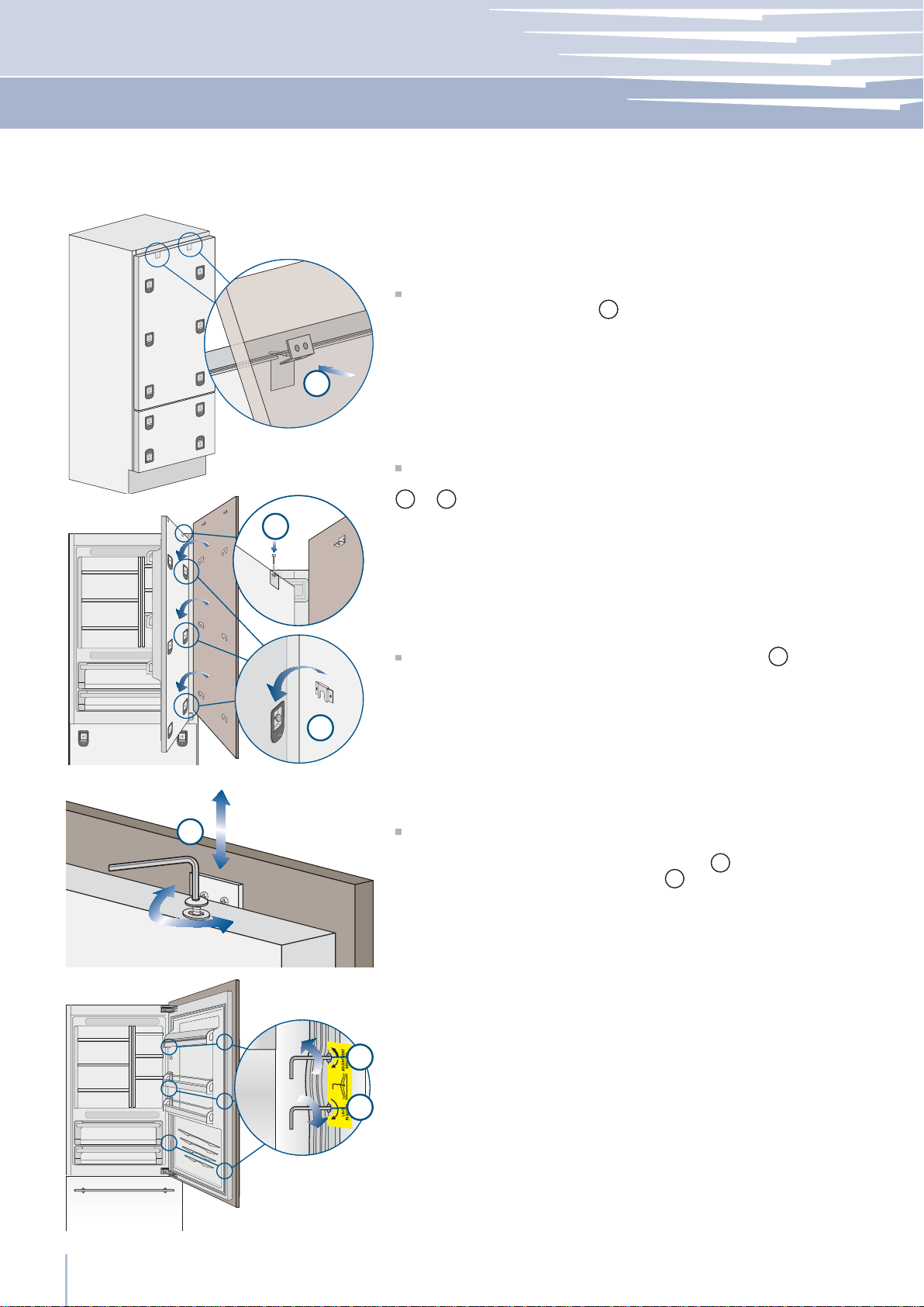
Hook the panel to the fixing devices starting from the top aligning
brackets 6.
6
At this point, alignment between the panel and adjacent cabinets can be adjusted using the alignment brackets and small brackets 7 and 8.
7
Vertical alignment: tighten or loosen the screw in the brackets to
raise or lower the panel 9.
8
9
Depth alignment: working from the inside of the door, after lifting up the magnetic seal, adjust the panel position so it is closer to
or further away from the door using the holes
panel in position using the holes
11
.
and then fix the
10
10
www.fhiaba.com · www.thevettagroup.com
24
11
Page 27
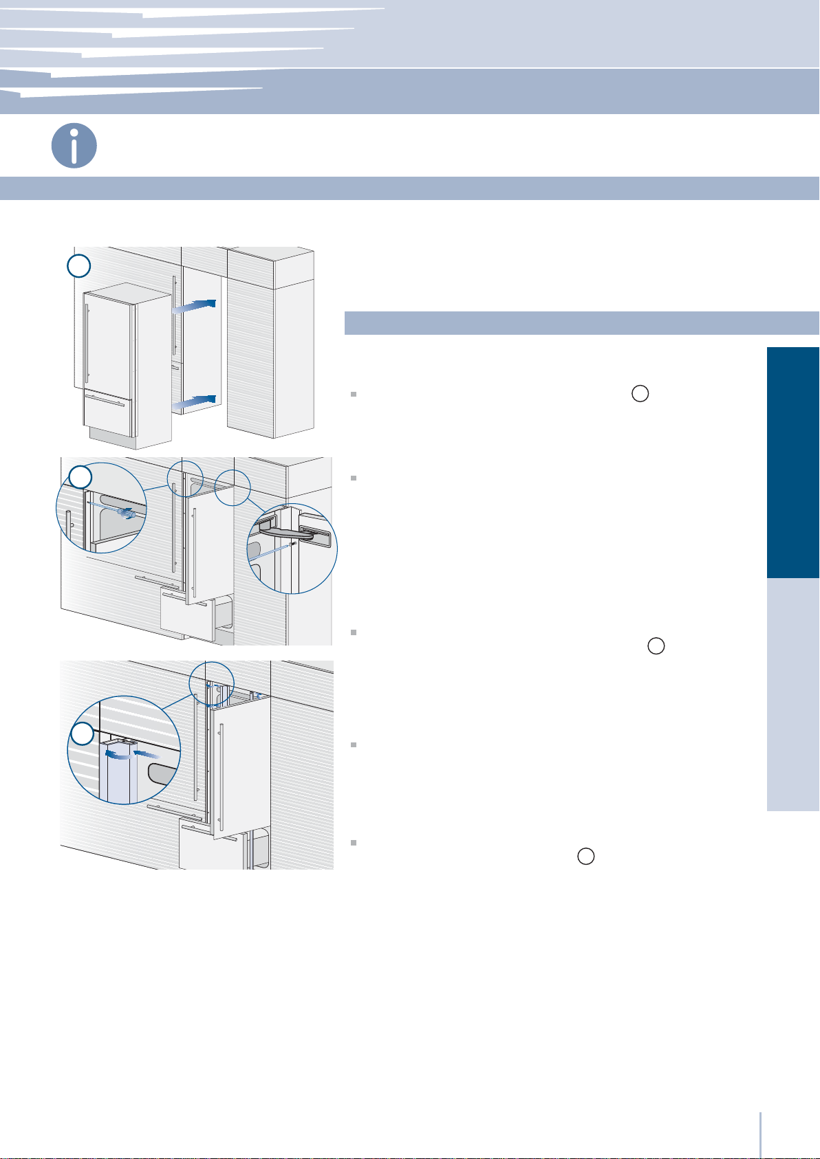
IMPORTANT: The following instruction for installation apply to all Fhiaba models.
Installation Guide
Series: All
Installation
Built-in installation single appliance
For a built-in installation, to close gaps between the appliance and
the adjacent cabinets, special side proÀ les and aluminum covering
frames are provided.
1
Operate as follows:
Push the appliance into the installation niche 1.
2
If the unit is to be installed inside a niche or within an enclosed structure, it is necessary to design a ventilation shaft at the back of the niche to assure proper ventilation at the back of the unit. A 5 mm (1/4”)
gap is sufÀ cient to prevent overheating. Always mount front panels on
door and drawer before pushing the unit into its À nal position inside the
niche or structure.
EnglishFrançais
Secure the appliance to the adjacent cabinets by À xing to these the
side proÀ les previously mounted on the appliance 2.
To make this operation easier keep the door and the drawer open.
3
Check the levelling of the appliance, adjusting its feet and wheels
to correct it.
Mount the proÀ les the covering frames: À rst insert them laterally and
then push À rmly until a “click” is heard 3.
www.fhiaba.com · www.thevettagroup.com
25
Page 28
Series: All
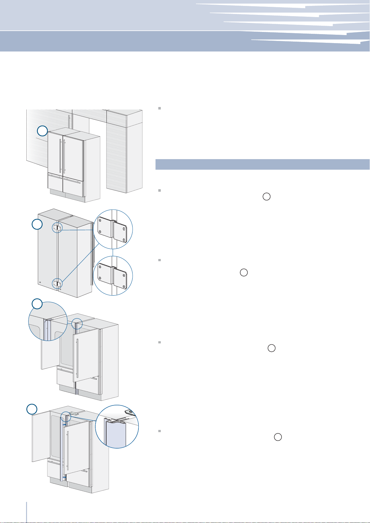
Built-in installation two or more appliances
1
2
Required accessories to be ordered separately:
Central connection Kit (KCC)
Special side proÀ les and aluminum covering frames are provided for
closing gaps between the appliance and the adjacent cabinets.
Operate as follows:
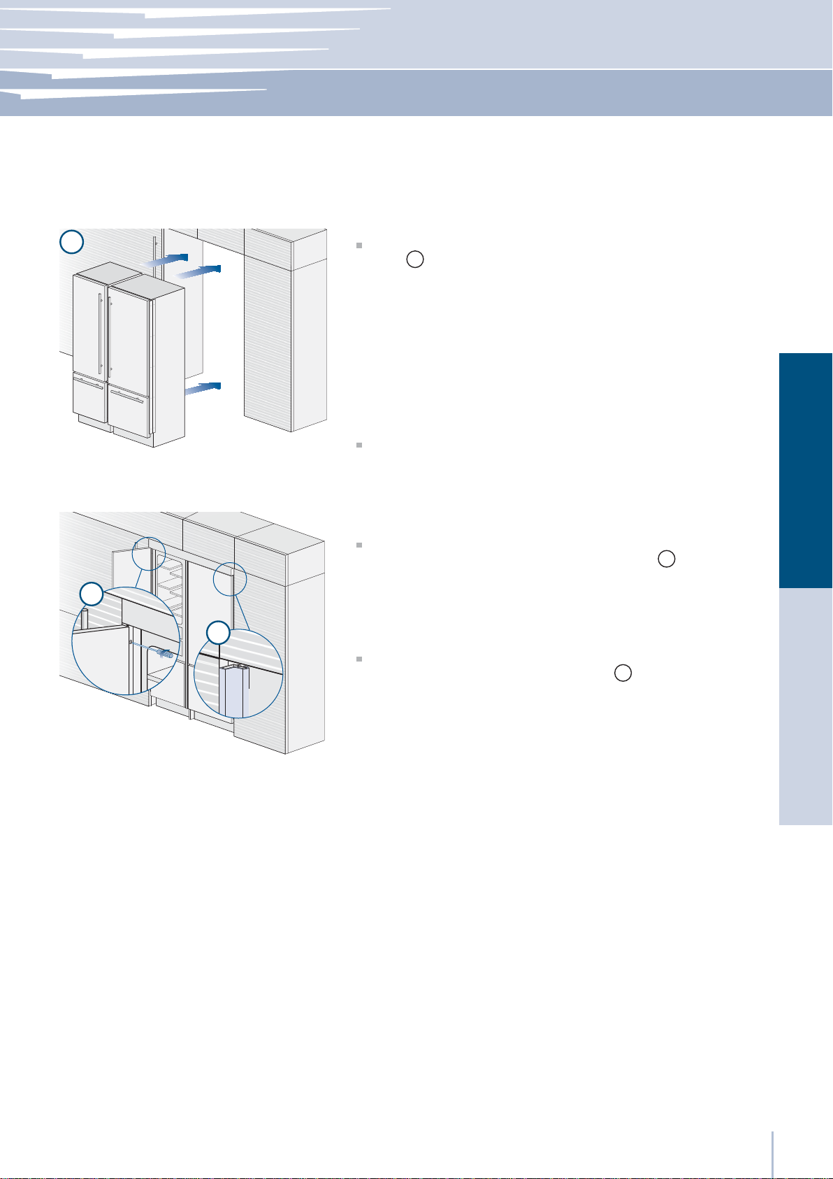
Position the appliances in front of the installation area, leaving
enugh space to operate at their back 1.
Move at the back of the appliances to mount the joining brackets:
À x on side of the top and lower brackets to one of the appliances
and subsequently to the other 2.
3
Place the two units side by side and join them at the front attaching
the two proÀ les with the supplied screws 3.
4
Finish off by mounting the central cover frame onto the central
profiles, by pushing it until a click is heard
.
4
www.fhiaba.com · www.thevettagroup.com
26
Page 29
Installation Guide
Series: All
5
Once the previous steps are complete, push the units in their À nal
position 5.
If the units are to be installed inside a niche or within an enclosed
structure, it is necessary to design a ventilation shaft at the back of
the niche to assure proper ventilation at the back of the unit. A 5 mm
gap is sufÀ cient to prevent overheating. Always mount front panels on
door and drawer before pushing the unit into its À nal position inside the
niche or structure.
Check the levelling of the appliance, adjusting its feet and wheels
to correct it.
EnglishFrançais
Secure the appliance to the adjacent cabinets by À xing to these the
side proÀ les previously mounted on the appliance 6.
To make this operation easier keep the door and the drawer open.
6
7
Mount the covering frames onto the proÀ les, À rst insert them laterally
and then push À rmly until a “click” is heard 7.
www.fhiaba.com · www.thevettagroup.com
27
Page 30
Series: Integrated
Anti-tipping safety assembly
”)
5⁄8
45 (1
”)
3⁄8
2
59 (
152 (6”)
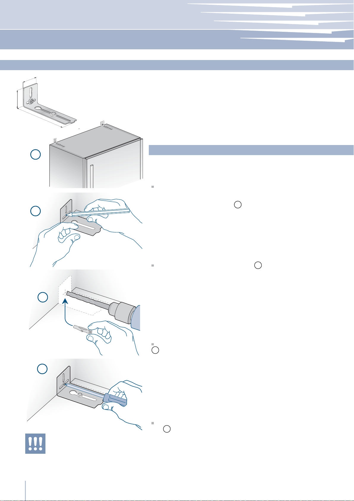
To prevent the appliance from tipping over an extra-long kit is vailable
up on request if the appliance needs to remain distanced from the
wall, it is mandatory to install two brackets on the upper part of the
appliance for À xing it securely to the wall.
1
Operate as follows:
The brackets should be applied as illustrated using the provided
screws and expansion plugs.
Place a bracket on the top of the appliance in correspondence to the
À xing holes and against the wall 1.
2
Mark up the holes position on the wall 2.
3
4
To avoid danger of the appliance tipping over
it is mandatory to secure the appliance to the
wall by means of two special brackets.
www.fhiaba.com · www.thevettagroup.com
28
Drill the wall with an 8 mm (3/8”) bit and insert the expansion plug
.
3
Reposition the bracket and À x it À rst to the cabinet and then to the
wall 4.
Page 31
Installation Guide
Series: StandPlus/X-Pro
Anti-tipping safety assembly
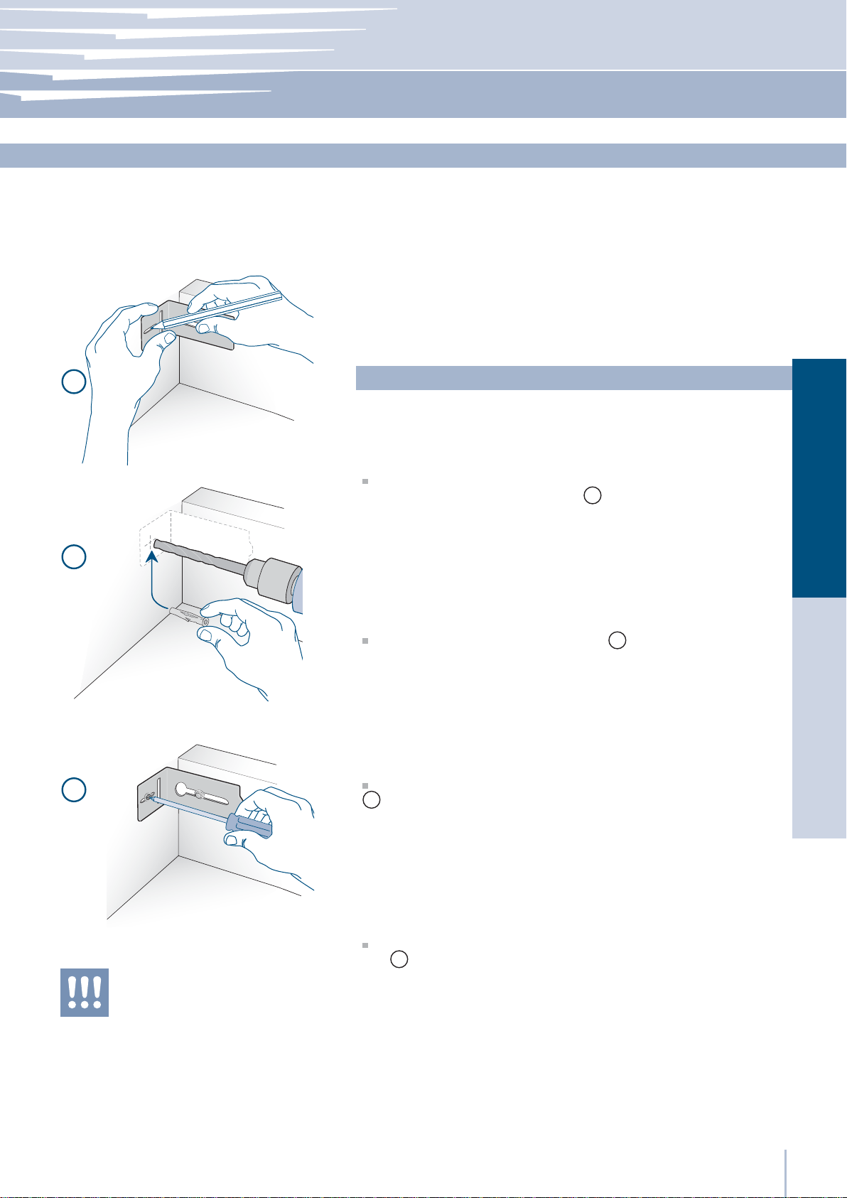
To avoid danger of the appliance tipping over when opening full doors
and drawers, it is mandatory to install two brackets on the upper part
of the appliance for À xing it securely to the wall.
The brackets should be applied as illustrated using the provided screws
and expansion plugs.
1
Operate as follows:
Place a bracket on the top of the appliance in correspondence to
the À xing holes and against the wall 1.
EnglishFrançais
2
Mark up the holes position on the wall 2.
3
Drill the wall with an 8 mm (3/8”) bit and insert the expansion plug
3
.
To avoid danger of the appliance tipping over
it is mandatory to secure the appliance to the
wall by means of two special brackets.
Reposition the bracket and À x it À rst to the cabinet and then to the
wall 4.
www.fhiaba.com · www.thevettagroup.com
29
Page 32
Series: StandPlus/X-Pro
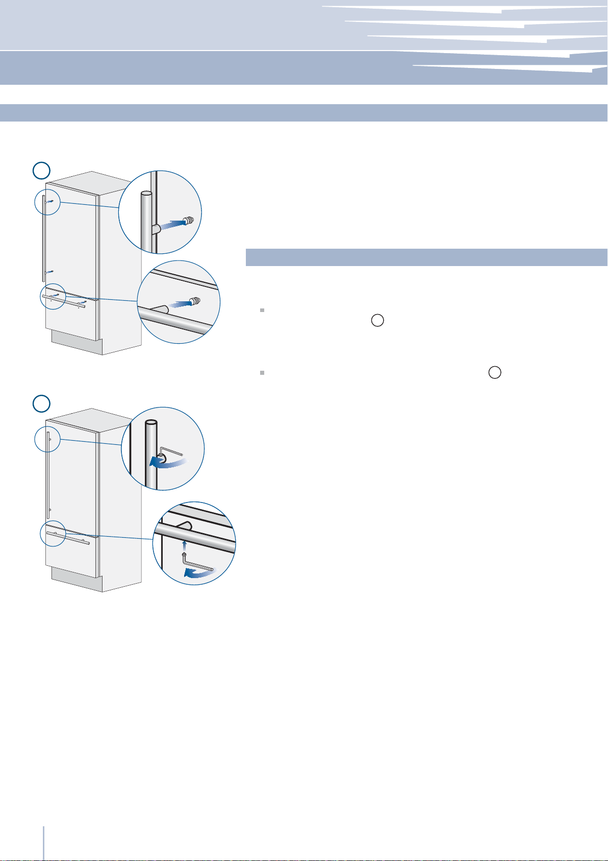
Mounting handles on stainless front
1
To mount the handles onto the door and the drawer operate as follows:
Operate as follows:
Insert the two handle spacers onto the supports already available on
the door and the drawer 1.
Screw in the Allen screws available on the handle 2.
2
The screws must be tightened in by means of a 2.5 mm (1/8”) hex
wrench.
www.fhiaba.com · www.thevettagroup.com
30
Page 33
Installation Guide
Series: Integrated
Air circulation
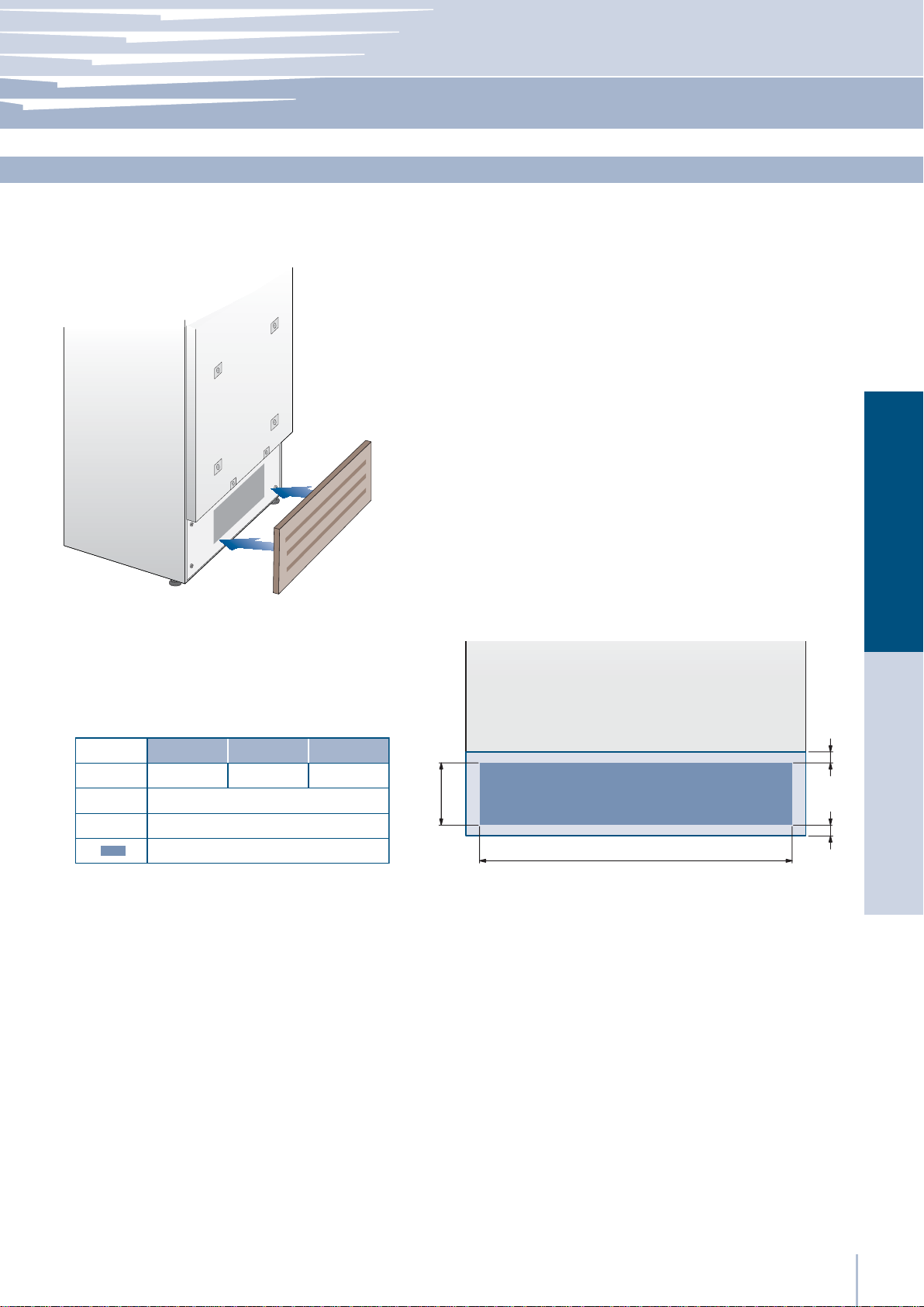
A forced air system assures ventilation through a grille positioned
in the lower front part of the unit. If the kitchen design includes a
kickplate, the latter has to be punched in order to maintain a satisfactory air Á ow, as described in the drawing. Holes can be in any
shape and size, as long as the total area of the punched part equals
50% of the kickplate are.
In this case, to guarantee a better air Á ow, it is advisable to remove
the front grille included with the unit. The grille is secured to the unit
with magnetic plates and can be easily removed even by the end
user, to provide for regular cleaning procedures and remove dust.
If the grille is partially covered by the kitchen kickplate, it is advisable
to remove the grille in order to provide for a better airÁ ow.
36 Series 30 Series 24 Series
A 860 (33 7⁄8”) 740 (29 1⁄8”) 560 (22”)
B
C
> 100 (4”)
10 (3⁄8”)
50%
EnglishFrançais
C
B
C
A
www.fhiaba.com · www.thevettagroup.com
31
Page 34
Series: StandPlus/X-Pro
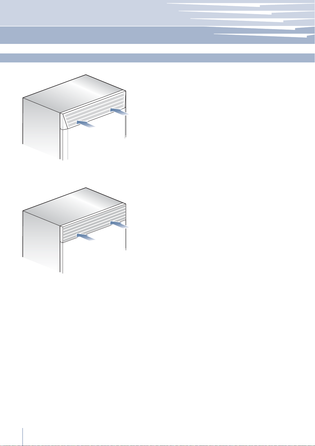
Ventilation
Ventilation is insured by a forced air system through a grille located in
the upper part of the appliance.
This grille should never be covered by panels or any other devices that
could reduce its efÀ ciency.
Please refer to page 5-6 to ensure correct air circulation.
www.fhiaba.com · www.thevettagroup.com
32
Page 35

Installation Guide
Series: All
Post installation control
Check that the front levelling feet have been properly installed.
Check that the connection to the water system does not have any
leaks and that the closing tap is easily accessible.
Check that the electrical connection is correctly installed and that
the multipole switch and socket are easily accessible.
Check the perfect alignment of the appliance with adjacent
structures.
Check that all adhesive tape and external or internal temporary
protective devices have been removed.
Check the perfect closing of the doors and the smooth sliding of
the drawers and shelves.
EnglishFrançais
www.fhiaba.com · www.thevettagroup.com
33
Page 36
Series: All
Start up
UNIT
Before starting
3
Electronic Control
3.4
The innovative electronic control system designed by Fhiaba maintains constant temperature in multiple compartments and
displays it on the control panel. It also allows user interaction making it possible to personalize settings of various functions and
to alert the user with sound and/or visual messages should any malfunction occur in the appliance.
FRI
I
N
D
U
T
G
E
1234 5 67 98
1 Unit
2 Fridge
3 Menu
Up/down
4
Fridge
5 Display
Up/Down
6
Freezer
(TriMode)
7 Enter
8 Ice maker
9 Alarm
Main control panel
E
NT
C
E
I
E
A
M
KE
R
R
Switches the appliance (all compartments) between ON and STAND BY
(press for three seconds).
Allows switching on and off of only the refrigerator compartment
(press for three seconds).
Allows access to the appliance function menu
Using the Up and Down buttons, it is possible to change the set temperature of the refrigerator and navigate through the interactive menu.
It shows the temperature of the refrigerator and freezer compartments,
the date and time, Menu functions and visual messages.
By selecting Up/Down the preset temperature can be changed according to the selected function mode (freezer, refrigerator, Crisper-Fresco).
Confirms activation or deactivation of the selections made in the
Menu.
Allows activating or deactivating the automatic ice production.
Blinks to signal user alerts such as door left open, also in combination with
a sound signal which can be deactivated by pressing the button.
FR
IDGE
3.5
11 Display
12 Up/Down
13 Crisper
Before starting
Crisper-Fresco control panel
CRI
P
S
R
E
10 11 12
Shows the temperature of the Crisper-Fresco compartment.
Using the Up and Down buttons, it is possible to change the
temperature set for the Crisper-Fresco compartment.
Allows switching on and off of only the Crisper-Fresco compartment
(press
for three seconds).
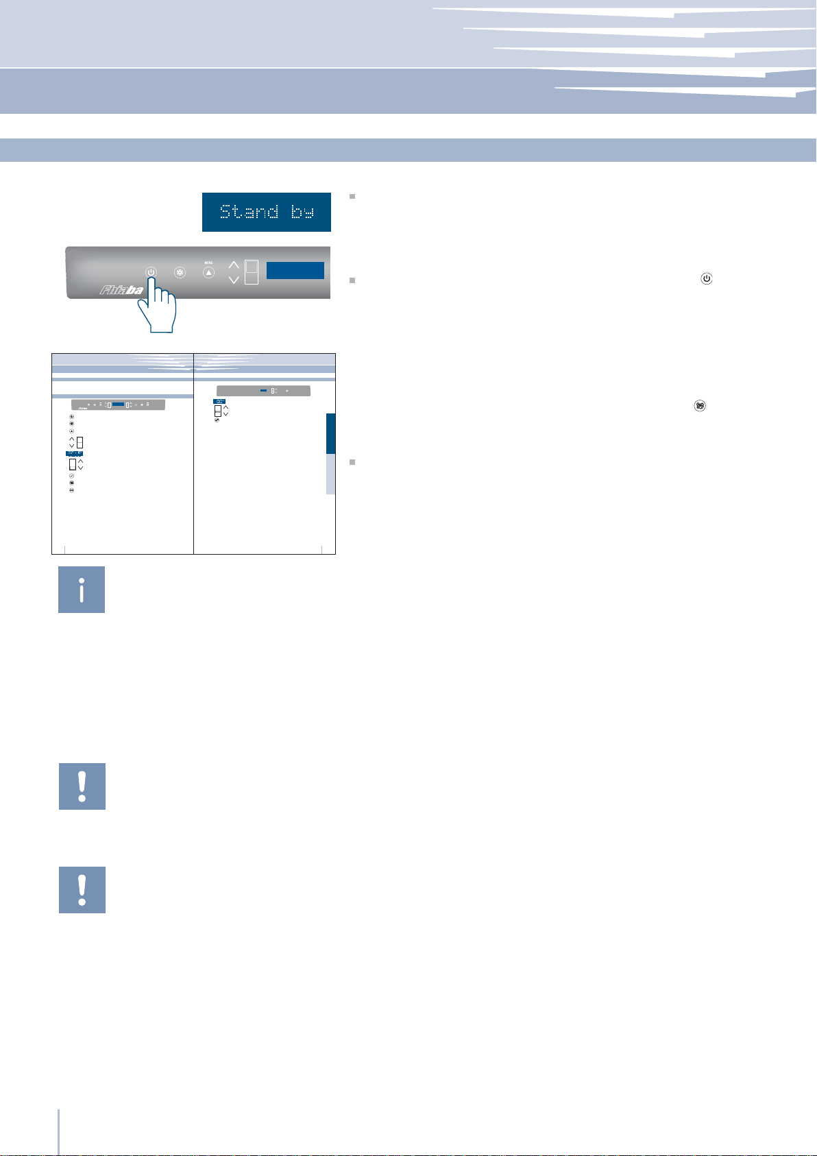
To start the appliance, connect the plug to the electrical mains: at
this point, when opening the door, the control panel will usually visualize the message “Stand by”, and all the panel keys be off
To turn on all the appliance compartments, press the Unit button
for three seconds. The display will show the message “Initial test” for
approx. 2 minutes. After this phase the compressors will start up and remain on until the default temperature set up in the factory is reached.
Do bear in mind that this condition could last several hours.
If the appliance is provided with an Ice Maker, prior to switching it
on make sure that the water À lter cartridge is installed, then À ll the
3
3.6
water system. To this purpose switch off the Ice Makerand performe a
manual clean procedure.
At the end switch the Ice Maker on again by touching the button.
EnglishFrançais
For further information about the appliance operation, refer to the
User Manual.
www.fhiaba.com ∙ www.thevettagroup.com
8
www.fhiaba.com ∙ www.thevettagroup.com
9
If at the À rst start - up the message Stand by does
not appear, but other messages appear, such
as Fridge too warm, Fresco too warm, Freezer
too warm, or sound signals are activated, it
means that the appliance has already started
the cooling process.
If this is the case, deactivate any possible acoustic signals by pressing the Alarm button, close
the door and wait until the set temperature is
reached.
It is necessary to let the unit reach the correct
temperature before foods are stored inside.
On models with a dedicated Fresco compartment, the Fresco compartment cools to the set
temperature (default 0°C / 32°F) prior to the
cooling system switching to the main refrigeration compartment.
www.fhiaba.com · www.thevettagroup.com
34
Page 37

Page
Indications importantes
3
Indications importantes concernant la sécurité
Pour la sécurité des enfants
Caractéristiques techniques
3
Caractéristiques de l’appareil et conditions requises pour l’installation
4
Caractéristiques de la niche d’installation Integrated
5
Caractéristiques de la niche d’installation StandPlus
6
Caractéristiques de la niche d’installation X-Pro
Préparation à l’installation
7
Transport sur le lieu d’installation et déballage
8
Dimensions de l’encastrement et Styles d’installation: Série Integrated
8
Dimensions de l’encastrement et Styles d’installation: Série StandPlus et série X-Pro
9
Types d’installation
10
Raccordements électrique et hydraulique
13
Mise à niveau
Notice d’Installation
Sommaire
EnglishFrançais
Montage des panneaux
14
Préparation des panneaux décoratifs pour la porte et Grands bacs
16
Préparation des panneaux décoratifs pour Réfrigérateur avec un Grand bac
17
Préparation des panneaux décoratifs pour Réfrigérateur avec deux Grand bac
18
Préparation des panneaux décoratifs pour Réfrigérateur avec porte vitrée et un Grand bac
19
Préparation des panneaux décoratifs pour Réfrigérateur avec porte vitrée et deux Grand bac
20
Dimensions des panneaux - Modèles avec un Grand Bac
21
Dimensions des panneaux - Modèles avec deux Grands bacs
22
Montage des poignées: Série Integrated
23
Fixation des panneaux à la porte et au Grand bac: Série Integrated
Installation dans la niche
25
Encastrement appareil unique
26
Encastrement combinaison
Achèvement de l’installation
28
Montage de la sécurité anti-renversement
30
Montage des poignées sur le devant inoxydable
31
Circulation de l’air
32
Ventilation
33
Contrôle de À n d’installation
34
Mise en marche
www.fhiaba.com · www.thevettagroup.com
1
Page 38

www.fhiaba.com · www.thevettagroup.com
2
Page 39
Notice d’Installation
Indications importantes concernant la sécurité
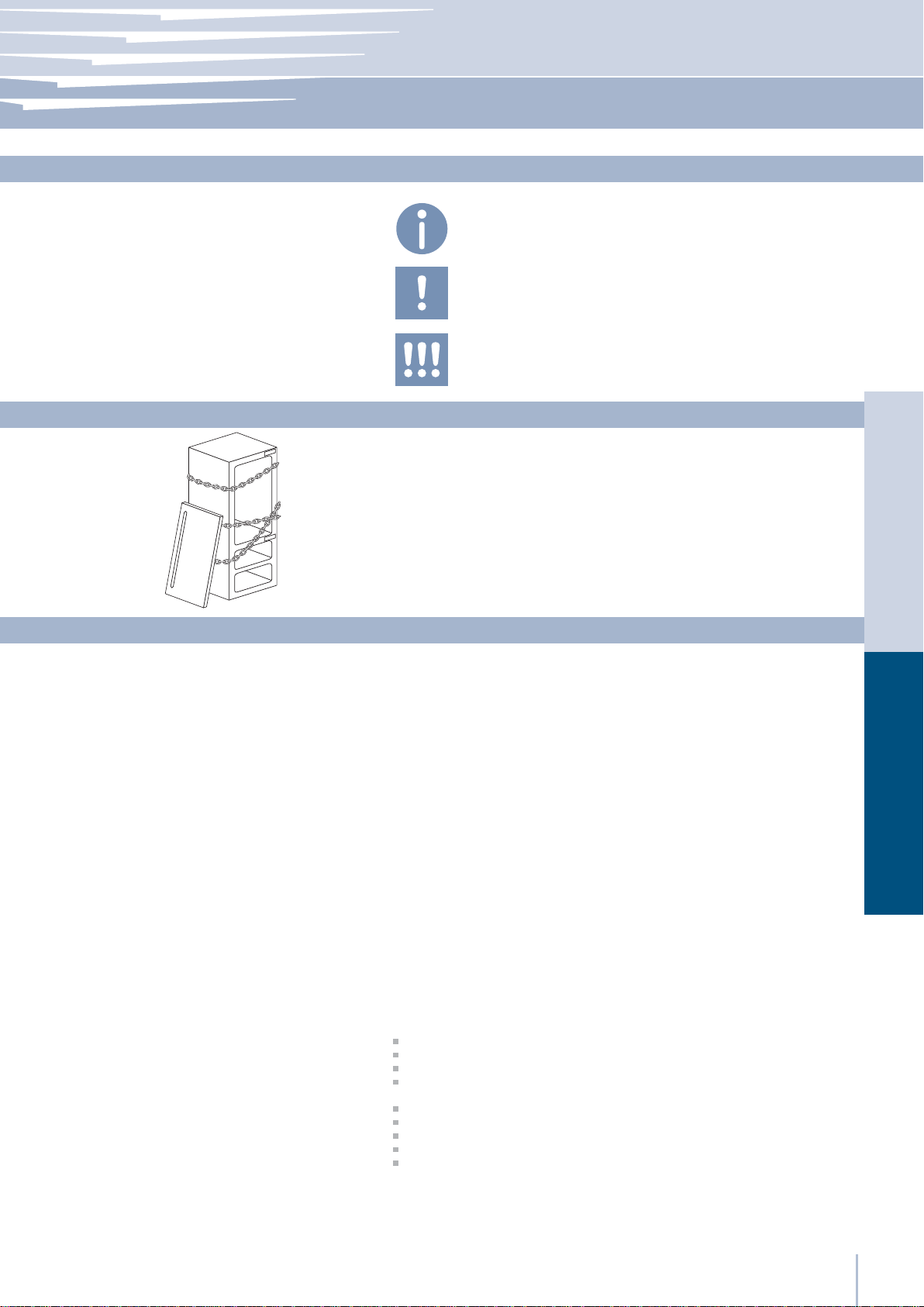
Symboles utilisés dans le manuel
Caractéristiques de l’appareil et conditions requises pour l’installation
Important
Indications aÀ n d’éviter tout
endommagement de l’appareil
Note
conseils pour une correcte utilisation
de l’appareil
Attention
indications aÀ n d’éviter toute
lésion aux personnes
Pour la sécurité des enfants
Si cet appareil remplace un autre appareil déjà existant qui doit être
mis de côté ou éliminé, veiller à ce que celui-ci ne devienne pas un
dangereux piège pour les enfants, en coupant le câble d’alimentation et en rendant impossible la fermeture de la porte.
EnglishFrançais
Dimensions de l’appareil
Integrated
Dimensions de l’appareil
StandPlus
Dimensions de l’appareil
X-Pro
Dimension de enballé
Poids avec emballage
Tension d’alimentation
Câble d’alimentation
Pression d’alimentation de l’eau potable
Tuyau d’alimentation de l’eau
Accessoires pour l’installation fournis
Équipement nécessaire
FI24 l: 599 mm (23 5/8”)/ h: 2120 mm (83 1/2”)/ p: 610 mm (24”)
FI30 l: 749 mm (29 1/2”)/ h: 2120 mm (83 1/2”)/ p: 610 mm (24”)
FI36 l: 899 mm (35 3/8”)/ h: 2120 mm (83 1/2”)/ p: 610 mm (24”)
FM24 l: 599 mm (23 5/8”)/ h: 2120 mm (83 1/2”)/ p: 629 mm (24 3/4”)
FM36 l: 899 mm (35 3/8”)/ h: 2120 mm (83 1/2”)/ p: 629 mm (24 3/4”)
FP24 l: 599 mm (23 5/8”)/ h: 2120 mm (83 1/2”)/ p: 635 mm (25”)
FP30 l: 749 mm (29 1/2”)/ h: 2120 mm (83 1/2”)/ p: 635 mm (25”)
FP36 l: 899 mm (35 3/8”)/ h: 2120 mm (83 1/2”)/ p: 635 mm (25”)
Série 24” l: 650 mm (25 5/8”) / h: 2260 mm (89”) / p: 800 mm (31 1/2”)
Série 30” l: 800 mm (31 1/2”) / h: 2260 mm (89”) / p: 800 mm (31 1/2”)
Série 36” l: 950 mm (37 3/8”) / h: 2260 mm (89”) / p: 800 mm (31 1/2”)
Série 24” max 230 kg (507 lb)
Série 30” max 275 kg (606 lb)
Série 36” max 295 kg (650 lb)
Modèle européen: AC 220-240V 50 Hz / Modèle américain: 110V 60Hz
Modèle européen: doté de À che Schuko 16 A / Modèle américain: 15A
de 0.05 MPa à 0.5 MPa (0.5 Bar - 5 Bar)
fourni, raccord femelle 3/4”, indiqué pour aliments
kit À xage des panneaux sur demande
Kit Anti-renversement (B04000200)
kit de raccordement latérale (KCLIT/KCLIH)
clé à six pans de 4 mm (1/8”)
tournevis cruciforme
perceuse à bois et à percussion
pointe pour bois de 2.5 mm (1/8”)
pointe pour mur de 8 mm (3/8”)
clé ouverte de 17 mm (3/4”)
Réglage de la hauteur des rouleaux arrière
13 mm (1/2”) douille
www.fhiaba.com · www.thevettagroup.com
3
Page 40
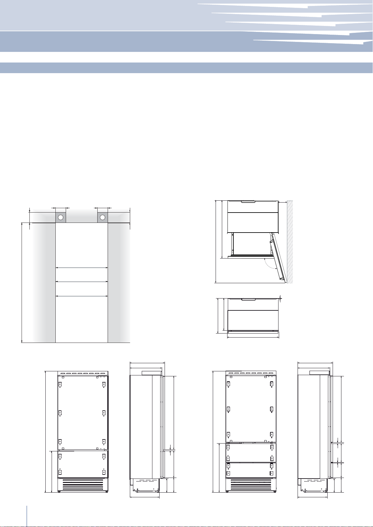
Caractéristiques de la niche d’installation: Série Integrated
A
espace à réserver aux équerres anti-renversement
Hauteur de l’encastrement
2134 mm (84”)
Largeur de l’encastrement
FI36: 900 mm (35 1/2”)
FI30: 750 mm (29 5/8”)
FI24: 600 mm (23 3/4”)
Encombrement avec porte ouverte
FI36: 1470 mm (57 7/8”)
FI30: 1320 mm (52”)
FI24: 1170 mm (46”)
Angle d’ouverture de la porte
105°
Largeur
FI36: 899 mm (35 3/8”)
FI30: 749 mm (29 1/2”)
FI24: 599 mm (23 5/8”)
Hauteur
2120 mm (83 1/2”) + 25 mm (1”)
Profondeur (sans panneau)
610 mm (24”)
140 (5 ½”) 140 (5 ½”)
100 (4”)
min 2134 (84”)
A A
FI36: 900 (35 ½”)
FI30: 750 (29 5⁄8”)
FI24: 600 (23 ¾”)
100 (4”)
610 (24”)
560 (22”)
992 (39”)
FI30: 1320 (52”)
FI24: 1170 (46”)
FI36: 1470 (57 7⁄8”)
560 (22”)
610 (24”)
FI36: 160 (6 3⁄8”)
FI30: 125 (5”)
FI24: 90 (3 ½”)
105°
10 (3⁄8”)
FI36: 899 (35 3⁄8”)
FI30: 749 (29 ½”)
FI24: 599 (23 5⁄8”)
610 (24”)
560 (22”)
2120 (83 ½”) +25 (1”)
721 (28 3⁄8”) +25 (1”)
www.fhiaba.com · www.thevettagroup.com
4
1293 (50 7⁄8” )
20 (¾”)
474 (18 5⁄8”)
25 (1”)
+ 25 (1”)
500 (19 ¾”) 500 (19 ¾”)
) +
)
1⁄8”
¾”
231 (9
248 (9
2120 (83 ½”) +25 (1”)
846 (33 ¼”) +25 (1”)
1168(46”)
20 (¾”)10 (3⁄8”)
25 (1”)
+ 25 (1”)
) +
)
1⁄8”
¾”
231 (9
248 (9
330 (13”)
)
¼”
259 (10
Page 41
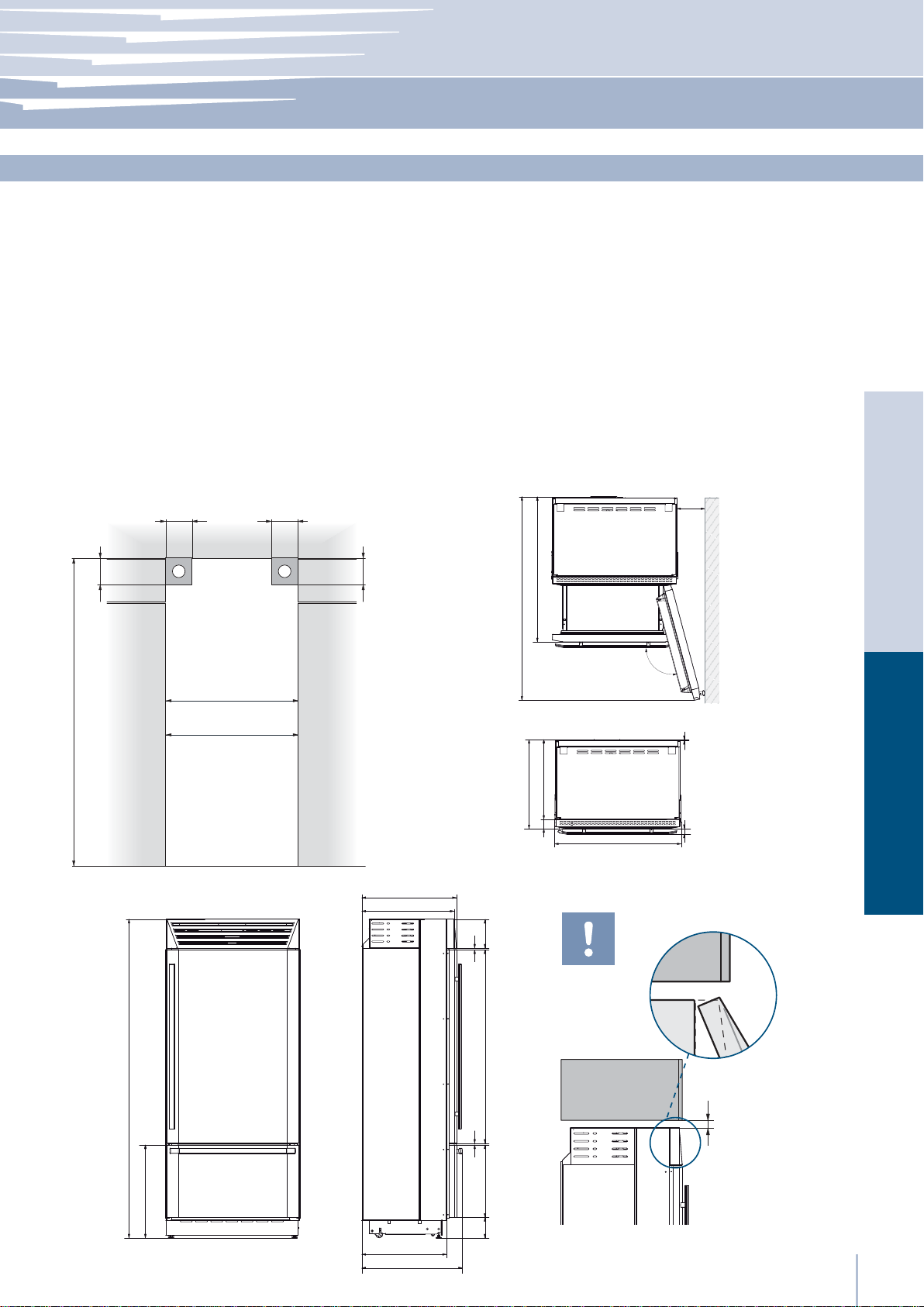
A
espace à réserver aux équerres anti-renversement
Hauteur de l’encastrement
2134 mm (84”)
Largeur de l’encastrement
FM36: 900 mm (35 1/2”)
FM24: 600 mm (23 3/4”)
Encombrement avec porte ouverte
FM36: 1470 mm (57 7/8”)
FM24: 1170 mm (46”)
Notice d’Installation
Caractéristiques de la niche d’installation: Série StandPlus
Angle d’ouverture de la porte
105°
Largeur
FM36: 899 mm (35 3/8”)
FM24: 599 mm (23 5/8”)
Hauteur
2120 mm (83 1/2”) + 25 mm (1”)
Profondeur
629 mm (24 3/4”)
140 (5 ½”) 140 (5 ½”)
100 (4”)
min 2134 (84”)
A A
FM36: 900 (35 ½”)
FM24: 600 (23 ¾”)
100 (4”)
629 (24 ¾”)
615 (24 ¼”)
FM36: 230 (9”)
FM24: 160 (6 ¼”)
EnglishFrançais
1010 (39 ¾”)
FM24: 1170 (46”)
FM36: 1470 (57 7⁄8”)
105°
10 (3⁄8”)
560 (22”)
629 (24 ¾”)
FM36: 899 (35 5⁄8”)
FM24: 599 (23 5⁄8”)
69 (2 ¾”)
IMPORTANT
8 (3⁄8”)
195 (7 5⁄8”)
37 (1 ½”)
2120 (83 ½”) +25 (1”)
613 (24 1⁄8”)+25 (1”)
560 (22”)
666 (26 ¼”)
1296 (50”)
8 (3⁄8”)
485 (19 1⁄8”)
128 (5) + 25 (1”)
Fil
min 10 (3⁄8”)
www.fhiaba.com · www.thevettagroup.com
5
Page 42
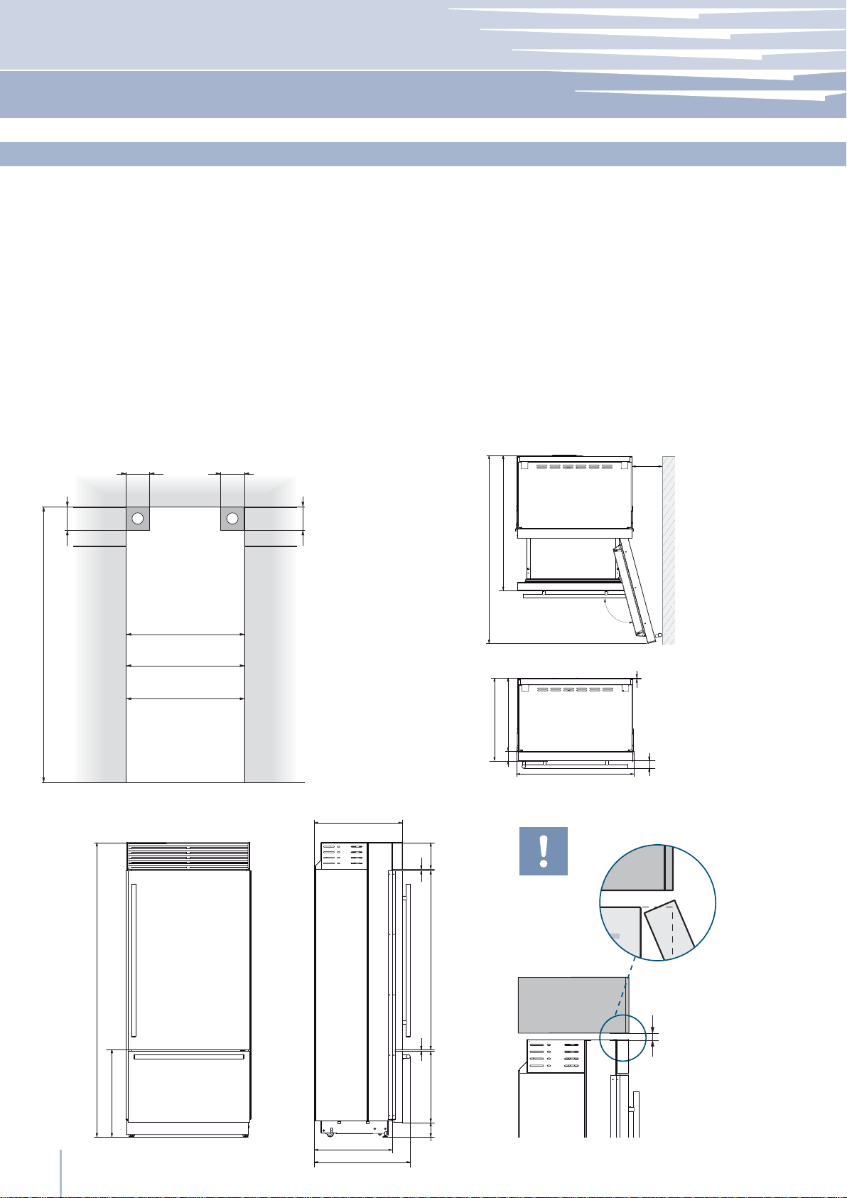
Caractéristiques de la niche d’installation: Série X-Pro
A
espace à réserver aux équerres anti-renversement
Hauteur de l’encastrement
2134 mm (84”)
Largeur de l’encastrement
FP36: 900 mm (35 1/2”)
FP30: 750 mm (29 5/8”)
FP24: 600 mm (23 3/4”)
Encombrement avec porte ouverte
FP36: 1470 mm (57 7/8”)
FP30: 1320 mm (52”)
FP24: 1170 mm (46”)
Angle d’ouverture de la porte
105°
Largeur
FP36: 899 mm (35 3/8”)
FP30: 749 mm (29 1/2”)
FP24: 599 mm (23 5/8”)
Hauteur
2120 mm (83 1/2”) + 25 mm (1”)
Profondeur
635 mm (25”)
140 (5 ½”) 140 (5 ½”)
100 (4”)
min 2134 (84”)
A A
FP36: 900 (35 ½”)
FP30: 750 (29 5⁄8”)
FP24: 600 (23 ¾”)
100 (4”)
635 (25”)
FP36: 230 (9”)
FP30: 195 (7 ¾”)
FP24: 160 (6 ¼”)
1016 (40”)
FP30: 1320 (52”)
FP24: 1170 (46”)
FP36: 1470 (57 7⁄8”)
105°
10 (3⁄8”)58 (2 ¼”)
635 (25”)
560 (22”)
FP36: 899 (35 3⁄8”)
75 (3”)
FP30: 749 (29 ½”)
FP24: 599 (23 5⁄8”)
IMPORTANT
8 (3⁄8”)
195 (7 5⁄8”)
2120 (83 ½”) +25 (1”)
613 (24 1⁄8”)+25 (1”)
www.fhiaba.com · www.thevettagroup.com
6
560 (22”)
693 (27 ¼”)
1296 (50”)
8 (3⁄8”)
485 (19 1⁄8”)
128 (5) + 25 (1”)
min 10 (3⁄8”)
Fil
Page 43
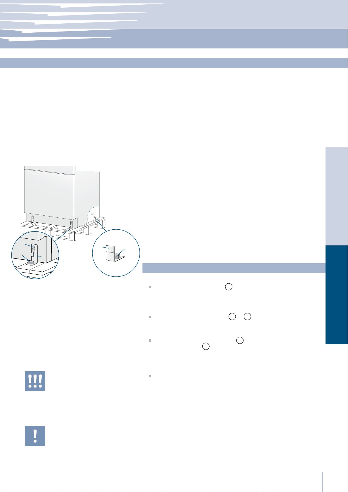
Notice d’Installation
Série: tous
Préparation à l’installation
Transport sur le lieu d’installation
et déballage
2
1
3
4
1
S’agissant d’un appareil lourd et de grandes dimensions, avant de
transporter l’appareil, s’informer sur les modalités d’accès au lieu où il
sera installé (dimensions des portes, espaces de mouvement dans les
escaliers, etc.).
L’appareil est À xé à la base de l’emballage (palette) moyennant qua-
tre boulons amovibles avec une clé de 17 mm (3/4»).
Il est conseillé d’utiliser un transporteur manuel pour manutentionner
l’appareil jusqu’à la zone où celui-ci sera installé et seulement alors
retirer la base de l’emballage.
L’appareil devrait toujours être transporté en position verticale.
Si cela n’est pas possible, transporter l’appareil couché sur le dos.
Une fois que l’on a atteint la zone prévue pour l’installation, enlever
les emballages, faire descendre l’appareil de la palette emballages
et faire descendre l’appareil de la palette.
Intervenir de la manière suivante:
EnglishFrançais
L’appareil est très lourd.
Faire très attention durant la manipulation
aÀ n d’éviter tout dommage aux personnes
et aux choses.
Transporter l’appareil en position verticale.
Éviter de manière absolue le transport sur la
partie frontale.
Enlever les quatre boulons 1 qui À xent l’appareil à la palette en
utilisant une clé ouverte de 17 mm (3/4»).
Retirer les crochets de À xation 3 et 4.
Pour retirer le crochet de À xation 3 , dévisser pour un ou deux tours
le boulon de réglage 2 de la roue arrière en utilisant une clé à douille
de 13 mm (1/2») .
De l’arrière de l’unité et au moyen d’un chariot diable de caractéristiques appropriées, retirer l’appareil et le poser sur le sol.
Faire très attention aÀ n d’éviter tout dommage au sol.
Les sols particulièrement délicats doivent être protégés avec des panneaux de faésite, compensé ou autre matériau adéquat.
www.fhiaba.com · www.thevettagroup.com
7
Page 44
Série: tous
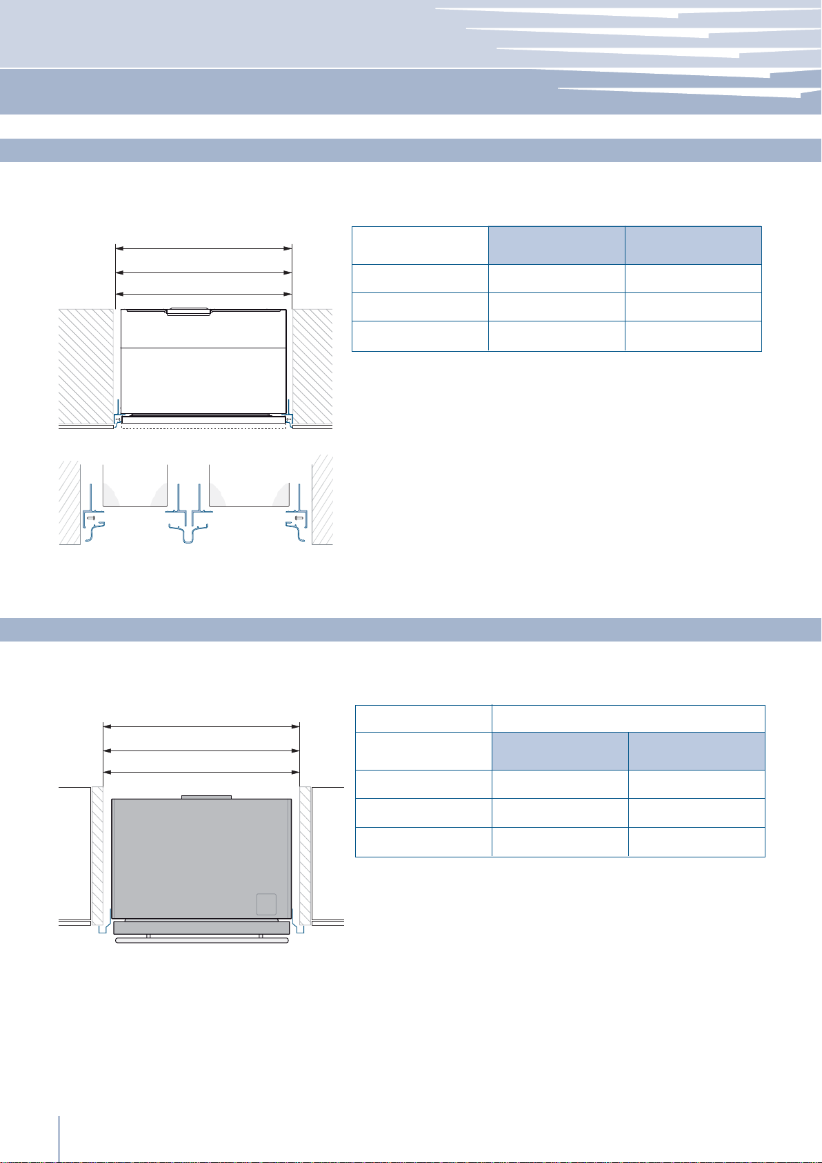
Dimensions de l’encastrement et Styles d’installation: Série Integrated
FI36: 900 (35 ½”)
Série
Niche
FI30: 750 (29 5⁄8”)
FI24: 600 (23 ¾”)
AAB
A KCLIT: Kit raccordement lateral
(non compris - doit être commandé
comme accessoire séparé)
B KCCIT: Kit raccordement central
(non compris - doit être commandé
comme accessoire séparé)
FI36
FI30
FI24
750 (29 5/8”)
600 (23 3/4”)
Dimensions de l’encastrement et Styles d’installation: Série StandPlus et X-Pro
Largeur de
panneaux
897 (35 1/4”)900 (35 1/2”)
747 (29 3/8”)
597 (23 1/2”)
Stand-Proud
36: 914 (36”)
30: 762 (30”)
24: 610 (24”)
Série
36
30
24
KCLXB: Kit raccordement lateral
(non compris - doit être commandé
comme accessoire séparé)
900 (35 1/2”)
750 (29 5/8”)
600 (23 3/4”)
NICHE
MAXMIN
914 (36”
762 (30”)
610 (24”)
)
www.fhiaba.com · www.thevettagroup.com
8
Page 45
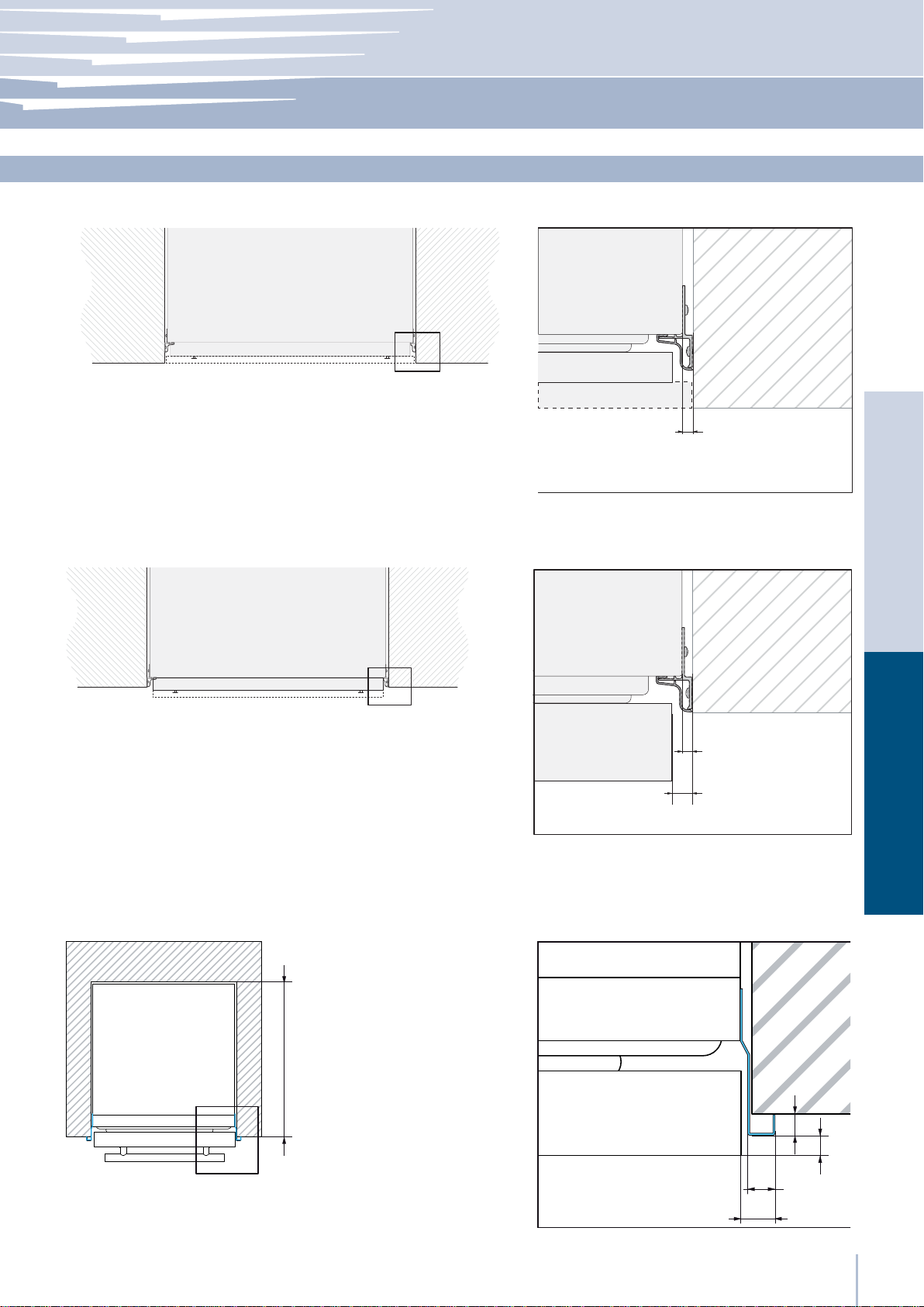
Montage à Á eur avec des garnitures en aluminium standards
A KCLIT: Kit raccordement lateral
(non compris - doit être commandé comme
accessoire séparé)
B KCCIT: Kit raccordement central
(non compris - doit être commandé comme
accessoire séparé)
Notice d’Installation
Série: tous
Types d’installation
A
B
6,5 (¼”)
L’installation Prominent avec des garnitures en aluminium standards
A KCLIT: Kit raccordement lateral
(non compris - doit être commandé comme
accessoire séparé)
B KCCIT: Kit raccordement central
(non compris - doit être commandé comme
accessoire séparé)
Stand-Proud (pur Série StanPlus et X-Pro)
Niche 610 mm (24”)
EnglishFrançais
A
B
6,5 (¼”)
10 (3⁄8”)
610 (24”)
KCLXB: Kit raccordement lateral
(non compris - doit être commandé
comme accessoire séparé)
)
5⁄8”
15 (
)
20 (¾”)
25 (1”)
www.fhiaba.com · www.thevettagroup.com
3⁄8”
10 (
9
Page 46
Série: tous
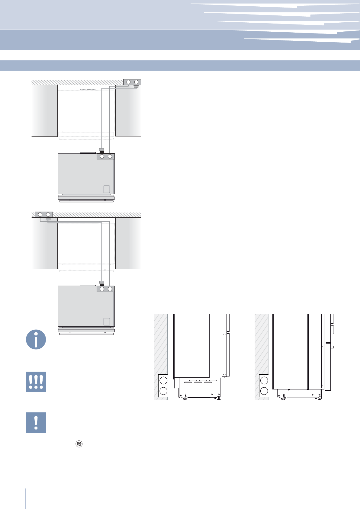
Raccordements électrique et hydraulique
E W
Les appareils sont livrés de l’usine pour le fonctionnement à 230V AC
- 50Hz (Europe, Royaume Uni et autres Pays) ou 115V AC - 60Hz (EtatsUnis et Canada).
Un câble d’alimentation avec À che équipé d’un contact de ter-
re sont fournis pour la connexion à une prise de 16A (Europe,
Royaume Uni et autres Pays) ou de 15A (Etats-Unis et Canada) .
Un disjoncteur doit également être installé et doit être facilement accessible aÀ n de mettre hors tension l’appareil avant d’effectuer toute
installation ou maintenance.
E W
EW
Pour le raccordement hydraulique (pour les appareils équipés de fabricateur de glace) il faut prévoir un robinet avec raccord mâle de
¾”, facilement accessible même lorsque l’appareil est installé.
Pour le raccordement au robinet, utiliser exclusivement le tuyau compris dans le Kit Utilisateur fourni avec l’appareil.
L’appareil doit être raccordé au réseau d’eau potable, en tenant
compte des dispositions en vigueur dans le pays où l’appareil est installé et en ayant soin d’installer la cartouche du À ltre à eau, fournie
avec l’appareil, en suivant les instructions jointes.
EW
Raccordements électrique et hydraulique derrière l’unité
Série Integrated Série StandPlus et X-Pro
Le À ltre Fhiaba ne peut pas rendre potable de
l’eau qui n’est pas destinée à la consommation alimentaire.
Ne pas utiliser de réductions ou de rallonges.
S’il faut fermer le robinet général, désactiver
d’abord l’Ice Maker
Access (faire référence au Manuel d’utilisation).
www.fhiaba.com · www.thevettagroup.com
10
à l’aide du Menu Fhiaba-
E
W
E
W
Page 47
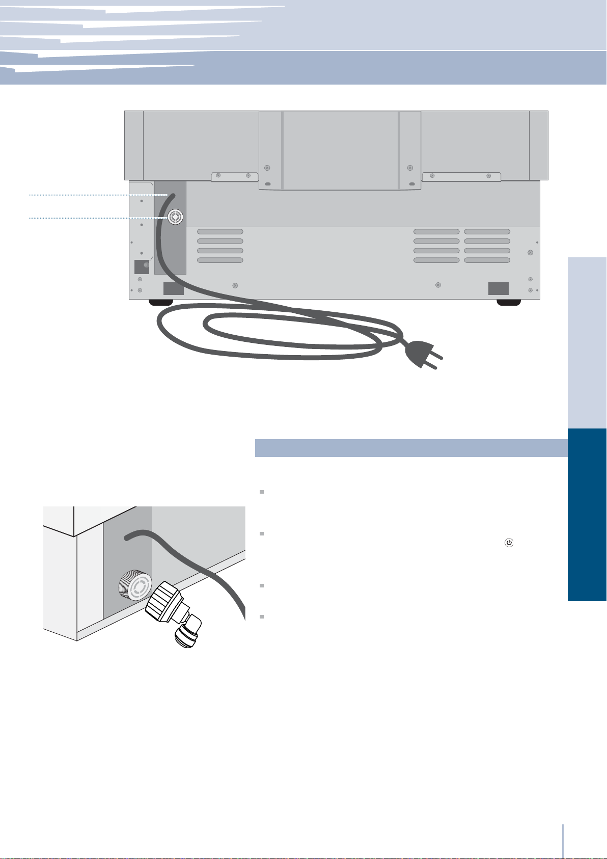
Branchement Électrique
Raccordement Hydraulique
Notice d’Installation
Série: Integrated
Arrière de l’appareil
Intervenir de la manière suivante:
Dérouler le câble électrique et le brancher directement à la prise
murale.
Contrôler que l’appareil soit en stand-by et que les voyants soient
éteints; dans le cas contraire, appuyer sur la touche Unit
dre l’appareil.
Raccorder le tuyau de l’eau au réfrigérateur dans la zone arrière.
Raccorder le tuyau au robinet en utilisant les garnitures comprises à
l’intérieur du Kit Utilisateur.
pour étein-
EnglishFrançais
www.fhiaba.com · www.thevettagroup.com
11
Page 48
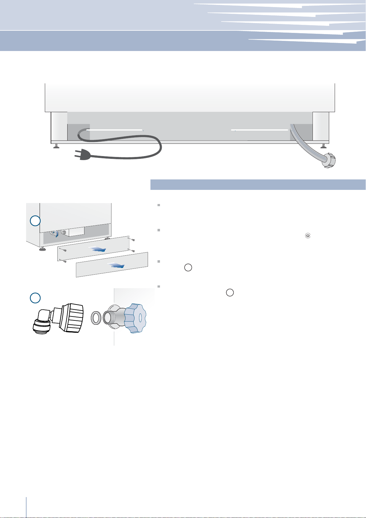
Série: StandPlus/X-Pro
Arrière de l’appareil
Avant de l’appareil
1
2
Branchement Électrique
Raccordement Hydraulique
Intervenir de la manière suivante:
Dérouler le câble électrique et le brancher directement à la prise
murale.
Contrôler que l’appareil soit en stand-by et que les voyants soient
éteints; dans le cas contraire, appuyer sur la touche Unit
pour étein-
dre l’appareil.
Reliez l’entrée d’eau avec la connection taraudée à la base de
l’appareil 1.
Raccorder le tuyau au robinet en utilisant les garnitures comprises à
l’intérieur du Kit Utilisateur 2.
www.fhiaba.com · www.thevettagroup.com
12
Page 49
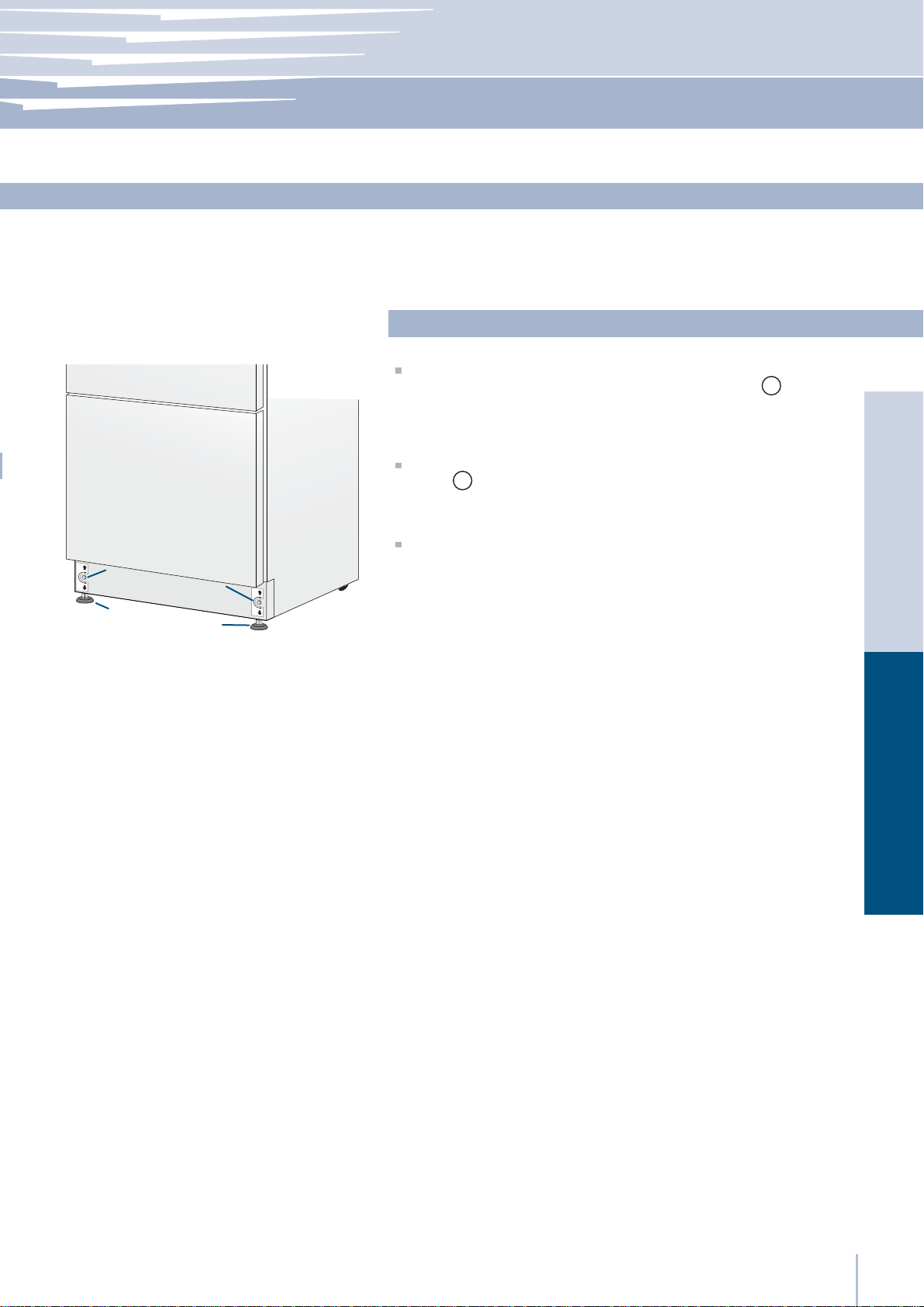
Notice d’Installation
Série: tous
Mise à niveau
Mettre à niveau l’appareil en réglant les pieds et les roues arrière à la
base de l’appareil.
Intervenir de la manière suivante:
Après avoir enlevé le socle (ou grille) inférieur (il est fixé par des
aimants), régler l’hauteur des pieds de mise à niveau 1 en utilisant
une clé ouverte de 17 mm (3/4»).
Ensuite régler l’hauteur des roues arrière en tournant les boulons de
réglage 2 dans le sens horaire ou anti-horaire comme nécessaire.
2
1
Remonter le socle (ou grille) inférieur ou la grille.
EnglishFrançais
2
1
www.fhiaba.com · www.thevettagroup.com
13
Page 50
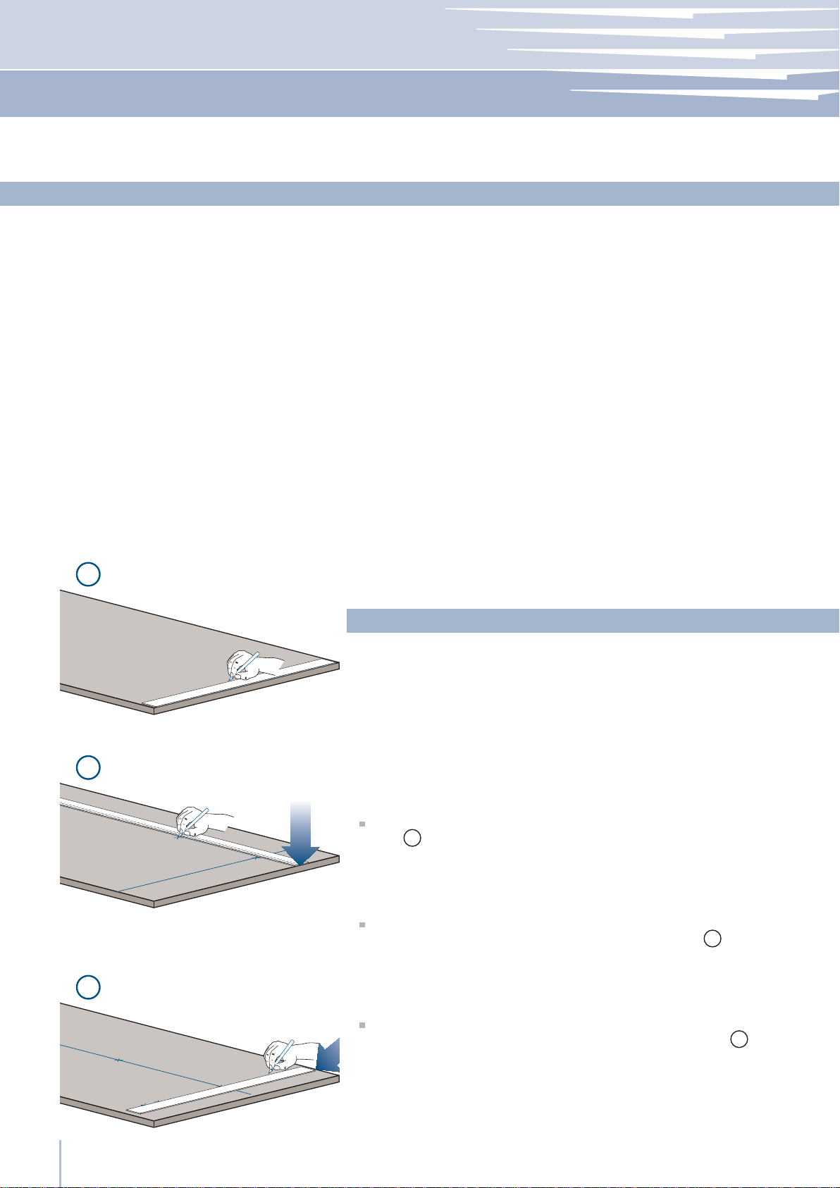
Série: Integrated
Préparation des panneaux décoratifs pour la porte et Grands bacs
Les dimensions des panneaux sont indiquées dans le tableau et sur les
dessins reportés ci-dessous.
Selon les exigences d’alignement avec d’autres meubles de la cuisine, le panneau de la porte du réfrigérateur peut être plus haut par
rapport à la ligne supérieure de la porte et le panneau inférieur peut
être plus bas par rapport à la ligne inférieure du grand bac.
Les panneaux sont montés moyennant des brides spéciales qui s’accrochent aux dispositifs de À xation réglables déjà prévus sur porte et
grand bac et moyennant des équerres qui bloquent et règlent verticalement le panneau.
Brides, équerres et vis de À xation correspondantes sont fournies avec
l’appareil et sont appliquées au panneau en suivant le schéma de
perçage reporté ci-dessous ou en utilisant le gabarit de perçage
prévu à cet effet et fourni.
1
Intervenir de la manière suivante:
Pour appliquer les brides aux panneaux, procéder de la manière suivante. Il est recommandé de monter les équerres avant de monter la
poignée.
2
Panneau de la porte
Tracer une ligne qui divise verticalement le panneau en deux parties
égales 1.
Partant du bas du panneau, marquer la hauteur à laquelle pratiquer
les trous (pour la distance des trous, voir les pages 16-19) 2.
3
www.fhiaba.com · www.thevettagroup.com
14
Suivre les données du tableau correspondant au modèle choisi,
marquer d’abord le trou le plus externe et puis le plus interne 3.
Page 51
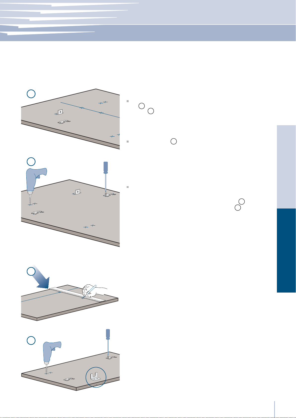
Notice d’Installation
Série: Integrated
4
VériÀ er la position des trous en appuyant les équerres sur les mar-
ques
panneau
Visser les équerres 6.
puis pratiquer les trous en faisant attention à l’épaisseur du
4
.
5
5
Panneau du grand bac
Pour le montage du panneau du grand bac, faire référence au
montage du panneau de la porte, avec la différence que les mesures
doivent être prises en partant du côté supérieur du panneau et non
pas du côté inférieur comme dans le cas de la porte
tournée de manière spéculaire à celle de la porte
7
et la bride est
.
8
EnglishFrançais
7
8
www.fhiaba.com · www.thevettagroup.com
15
Page 52
Série: Integrated
Préparation des panneaux décoratifs pour Réfrigérateur avec un Grand bac
Série 36
Charnière
Gauche
A
B
C
D
E
897 (35 ¼”) 897 (35 ¼”) 747 (29 3⁄8”) 747 (29 3⁄8”) 597 (23 ½”)
355.5 (14”)
418 (16
½”)
354.5 (14”) 354.5 (14”) 279.5 (11”) 279.5 (11”) 203.5(8”)
Charnière
Droite
261 (10 ¼”)
355.5 (14”)
¼”)
386 (15
418 (16
½”)
343 (13
311 (12
Série 30 Série 599
Charnière
Gauche
279 (11”)
187 (7 3⁄8”)
½”)
¼”)
Charnière
Droite
187 (7
279 (11”)
311 (12
343 (13
3⁄8”)
¼”)
½”)
Charnière
Gauche
205 (8
111 (4
276.5 (10 7⁄8”)
236.5 (9
1⁄8”)
3⁄8”)
3⁄8”)
Charnière
Droite
597 (23 ½”)
111 (4
3⁄8”)
1⁄8”)261 (10 ¼”)
205 (8
236.5 (9 3⁄8”)
276.5 (10 7⁄8”)386 (15 ¼”)
203.5(8”)F / G
Positionnement des trous
A
B C
13 (½”)
3⁄8”)
34 (1
¾”)
1285 (50 5⁄8”)
1163 (45
507.5 (20”)
¼”)
660 (26”)
157 (6
1⁄8”)
100 (4”)
382 (15
D E
D E
3⁄8”)
34 (1
½”)
13 (
F G
¾”)max 635 (25”)
min 1390 (54
www.fhiaba.com · www.thevettagroup.com
16
Page 53
Notice d’Installation
Série: Integrated
Préparation des panneaux décoratifs pour Réfrigérateur avec deux Grands bacs
A
B
C
D
E
F / G
Série 36
Charnière
Gauche
897 (35 ¼”) 897 (35 ¼”) 747 (29 3⁄8”) 747 (29 3⁄8”)
355.5 (14”)
261 (10
¼”)
418 (16
½”)
354.5 (14”) 354.5 (14”) 279.5 (11”) 279.5 (11”)
Charnière
Droite
261 (10 ¼”)
355.5 (14”)
¼”)
386 (15
418 (16
½”)
Charnière
Gauche
279 (11”)
187 (7 3⁄8”)
343 (13
311 (12
Série 30
½”)
¼”)
Charnière
Droite
187 (7
279 (11”)
311 (12
343 (13
3⁄8”)
¼”)
½”)386 (15 ¼”)
Positionnement des trous
A
B C
½”)
13 (
34 (1
3⁄8”)
EnglishFrançais
5⁄8”)
1⁄8”)
1160 (45
1044 (41
½”)
268 (10
½”)
292,5 (11
¼”)
183 (7
5⁄8”)
600 (23
5⁄8”) 157 (6 ¼”)
66 (2
7⁄8”)
73 (2
min 1265 (49 ¾”)
D E
¼”)max 415 (16 3⁄8”)
337 (13
D E
13 (½”)
F G
www.fhiaba.com · www.thevettagroup.com
17
Page 54
Série: Iintegrated
Préparation des panneaux décoratifs pour Réfrigérateur avec porte vitrée et un Grand bac
F / G
<200 (7 7⁄8”)
Série 36
Charnière
Gauche
A
D
E
H
I
897 (35 ¼”) 897 (35 ¼”)
½”)
418 (16
354.5 (14”) 354.5 (14”) 279.5 (11”) 279.5 (11”) 203,5(8”) 203,5(8”)
¼”)
412 (16
Charnière
Droite
386 (15
418 (16
380 (15”)
412 (16
¼”)
½”)
¼”)
Série 30
Charnière
Gauche
747 (29 3⁄8”) 747 (29 3⁄8”) 597 (23 ½”) 597 (23 ½”)
½”)
343 (13
311 (12 ¼”)
337 (13
¼”)
305 (12”)
Charnière
Droite
311 (12 ¼”)
343 (13 ½”)
305 (12”)
337 (13
¼”)
276.5 (10
236.5 (9 3⁄8”)
270.5 (10 5⁄8”)
230.5 (9
Série 24
Charnière
Gauche
7⁄8”)
1⁄8”)
Charnière
Droite
236.5 (9
276.5 (10 7⁄8”)386 (15 ¼”)
230.5 (9 1⁄8”)
270.5 (10
3⁄8”)
5⁄8”)380 (15”)
Positionnement des trousDimension trou pour porte
A
6,5 (
¼”)
6,5 (¼”)
135 (5
1075 (42 3⁄8”)
36: 627 (24 ¾”)
30: 477 (18
24: 327 (12
3⁄8”)
¾”)
7⁄8”)
135 (5
115 (4
3⁄8”)
½”)
3⁄8”)
1286 (50 5⁄8”)
1152,5 (45
507,5 (20”)
5⁄8”)
7⁄8”)
650,5 (25
148,5 (5
1⁄8”)
100 (4”)
382 (15
34 (1
3⁄8”)
H I
D E
3⁄8”)
34 (1
13 (
½”)
F G
min 1390 (54 ¾”)
max 635 (25”)
www.fhiaba.com · www.thevettagroup.com
18
Page 55
Notice d’Installation
Série: Integrated
Préparation des panneaux décoratifs pour Réfrigérateur avec porte vitrée et deux Grands bacs
Série 36 Série 30
Charnière
Gauche
A
897 (35 ¼”) 897 (35 ¼”)
Charnière
Droite
Charnière
Gauche
747 (29 3⁄8”) 747 (29 3⁄8”)
Charnière
Droite
135 (5
3⁄8”)
950 (37 3⁄8”)
36: 627 (24 ¾”)
30: 477 (18 ¾”)
24: 327 (12
7⁄8”)
135 (5
D
E
F / G
H
I
<200 (7 7⁄8”)
3⁄8”)
418 (16
½”)
386 (15
¼”)
354.5 (14”) 354.5 (14”) 279.5 (11”) 279.5 (11”)
¼”)
412 (16
380 (15”)
386 (15
418 (16
380 (15”)
412 (16
¼”)
½”)
¼”)
½”)
343 (13
311 (12 ¼”)
337 (13
¼”)
305 (12”)
311 (12 ¼”)
343 (13 ½”)
305 (12”)
337 (13
¼”)
Positionnement des trousDimension trou pour porte
3⁄8”)
1161 (45 ¾”)
1026,7 (40
1⁄8”)
7⁄8”)
6,5 (
34 (1
¼”)
3⁄8”)
EnglishFrançais
A
6,5 (¼”)
min 1265 (49 ¾”)
115 (4
½”)
½”)
¼”)
183 (7
292,5 (11
588 (23
149,5 (5
5⁄8”)
66 (2
268 (10 ½”)
7⁄8”)
73 (2
H I
¼”)
337 (13
D E
3⁄8”)
13 (½”)
F G
www.fhiaba.com · www.thevettagroup.com
max 415 (16
19
Page 56
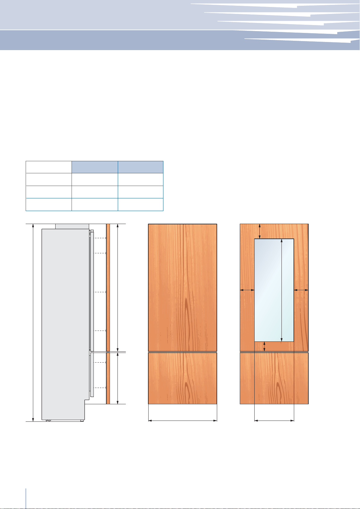
Série: Integrated
Dimensions des panneaux - Modèles avec un Grand Bac
Il est possible d’utiliser des panneaux avec des épaisseurs allant entre 18 mm (3/4 in) et 28 mm (1 1/8 in).
Les panneaux de porte avec un poids max de 23 kg (51 lb) et panneaux de grand bac avec poids max de 11 kg (25 lb)
Excéder ces poids pourrait annuler la garantie de tous les problèmes de services qui peuvent être attribués à des panneaux en surpoids.
Le mécanisme de charnière sur les appareils Fhiaba est considéré comme `zéro dégagement`. Les largeurs de portes
et de tiroirs spécifiées ci-dessous supposent la largeur de niche minimum est utilisé et une de 3,5 mm (1/8 “) révèlent
l’on souhaite autour des panneaux. Ajuster les dimensions de votre écran en fonction de vos propres critères de conception compte tenu de la largeur de votre créneau et votre révèlent. Jeu minimum / écart ne doit pas être inférieure
à 1,5 mm (1/16 “).
Séries
FI36
FI30
FI24
Largeur de la porte
et de tiroir A
Porte: Largeur de la
coupure B
627 (24 3/4”)897 (35 1/4”)
477 (18 3/4”)747 (29 3/8”)
327 (12 7/8”)597 (23 1/2”)
1390 (54 ¾”)
135
(5 3⁄8”)
min 200 (7 7⁄8”)
135
(5 3⁄8”)
1075 (42 3⁄8”)
2121 (83 ½") + 25 (1")
Exemples:
84” hauteur de l’encastrement
36” largeur de l’encastrement
4” hauteur de plinthe
1/8” distance désirée autour
www.fhiaba.com · www.thevettagroup.com
20
3 (1⁄8”)
max 635 (25”)
min 540 (21 ¼”)
115 (4 ½”)
A B
Door panel:
Largeur: 35-3/4”
Hauteur: 54-3/4”
Drawer panel:
Largeur: 35-3/4”
Hauteur: 84”-1/8”-54-3/4”-1/8”-4”=25”
If you want a 6” toe kick height then your bottom drawer
panel height would be 23”
Page 57
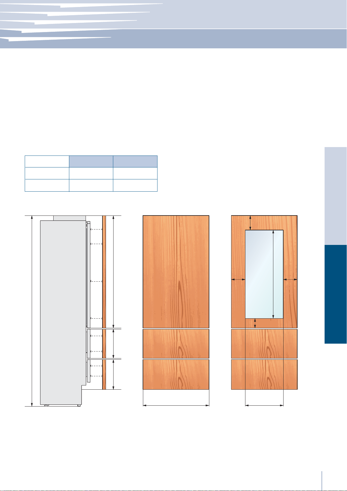
Notice d’Installation
Série: Integrated
Dimensions des panneaux - Modèles avec deu x G ra nds b ac s
Il est possible d’utiliser des panneaux avec des épaisseurs allant entre 18 mm (3/4 in) et 28 mm (1 1/8 in).
Les panneaux de porte avec un poids max de 23 kg (51 lb) et panneaux de grand bac avec poids max de 11 kg (25 lb)
Excéder ces poids pourrait annuler la garantie de tous les problèmes de services qui peuvent être attribués à des panneaux en surpoids.
Le mécanisme de charnière sur les appareils Fhiaba est considéré comme `zéro dégagement`. Les largeurs de portes
et de tiroirs spécifiées ci-dessous supposent la largeur de niche minimum est utilisé et une de 3,5 mm (1/8 “) révèlent
l’on souhaite autour des panneaux. Ajuster les dimensions de votre écran en fonction de vos propres critères de conception compte tenu de la largeur de votre créneau et votre révèlent. Jeu minimum / écart ne doit pas être inférieure
à 1,5 mm (1/16 “).
Séries
FI36
FI30
2121 (83 ½") + 25 (1")
Largeur de la porte
et de tiroir A
897 (35 1/4”)
747 (29 3/8”)
Porte: Largeur de la
coupure B
627 (24 3/4”)
477 (18 3/4”)
3 (1⁄8”)
135
(5 3⁄8”)
min 200 (7 7⁄8”)
950 (37 3⁄8”)
115 (4 ½”)
EnglishFrançais
135
(5 3⁄8”)
Exemples:
84” hauteur de l’encastrement
36” largeur de l’encastrement
4” hauteur de plinthe
1/8” distance désirée autour
337 (13 ¼”) 1265 (49 ¾”)
3 (1⁄8”)
min 325 (12 ¾”)
max 415 (16 3⁄8”)
A B
Door panel:
Largeur: 35-3/4”
Hauteur: 54-3/4”
Drawer panel:
Largeur: 35-3/4”
Hauteur: 84”-1/8”-54-3/4”-1/8”-4”=25”
If you want a 6” toe kick height then your bottom drawer
panel height would be 23”
www.fhiaba.com · www.thevettagroup.com
21
Page 58
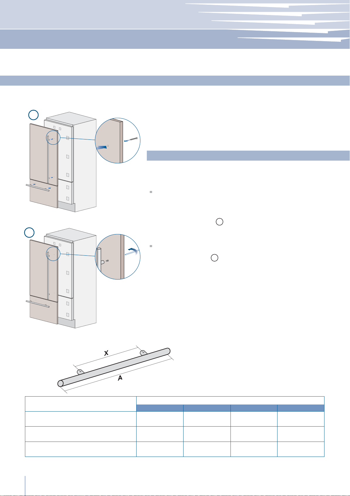
Série: Integrated
Montage des poignées: Sèrie Integrated
1
Les poignées doivent être montées sur le panneau décoratif de la
porte et du grand bac avant que les panneaux ne soient À xés au
réfrigérateur.
Intervenir de la manière suivante:
Après avoir pratiqué deux trous de 5 mm (1/4”) sur le côté arrière
des panneaux, insérer les vis fournies à la distance indiquée sur le tableau, reportée ci-dessous, l’une de l’autre. Pour centrer la poignée
horizontale Fhiaba (code HV) au centre de la porte, diviser en deux
la hauteur du panneau et pratiquer un trou à -45 cm (-17 3/4”) et un
autre à +45 cm (+17 3/4”) 1.
2
Positionner la poignée au niveau du trou sur le côté avant du panneau; insérer par l’arrière du panneau la vis fournie, à travers le trou,
et la visser à la poignée 2.
Longueur A
Entraxe X
Série
Utiliser la même procédure pour le montage des poignées horizontales sur les grands bacs. Pour la mesure de l’entraxe, faire référence
au tableau joint.
Code poignée
HO5
494 mm
(19 5/8”)
340 mm
(13 3/8”)
599
1104 mm
(43 1/2”)
900 mm
(35 1/2”)
899
749
599
HO8HV
794 mm
(31 1/4”)
480 mm
(18 7/8”)
899
HO7
644 mm
(25 3/8”)
490 mm
(19 1/4”)
749
www.fhiaba.com · www.thevettagroup.com
22
Page 59
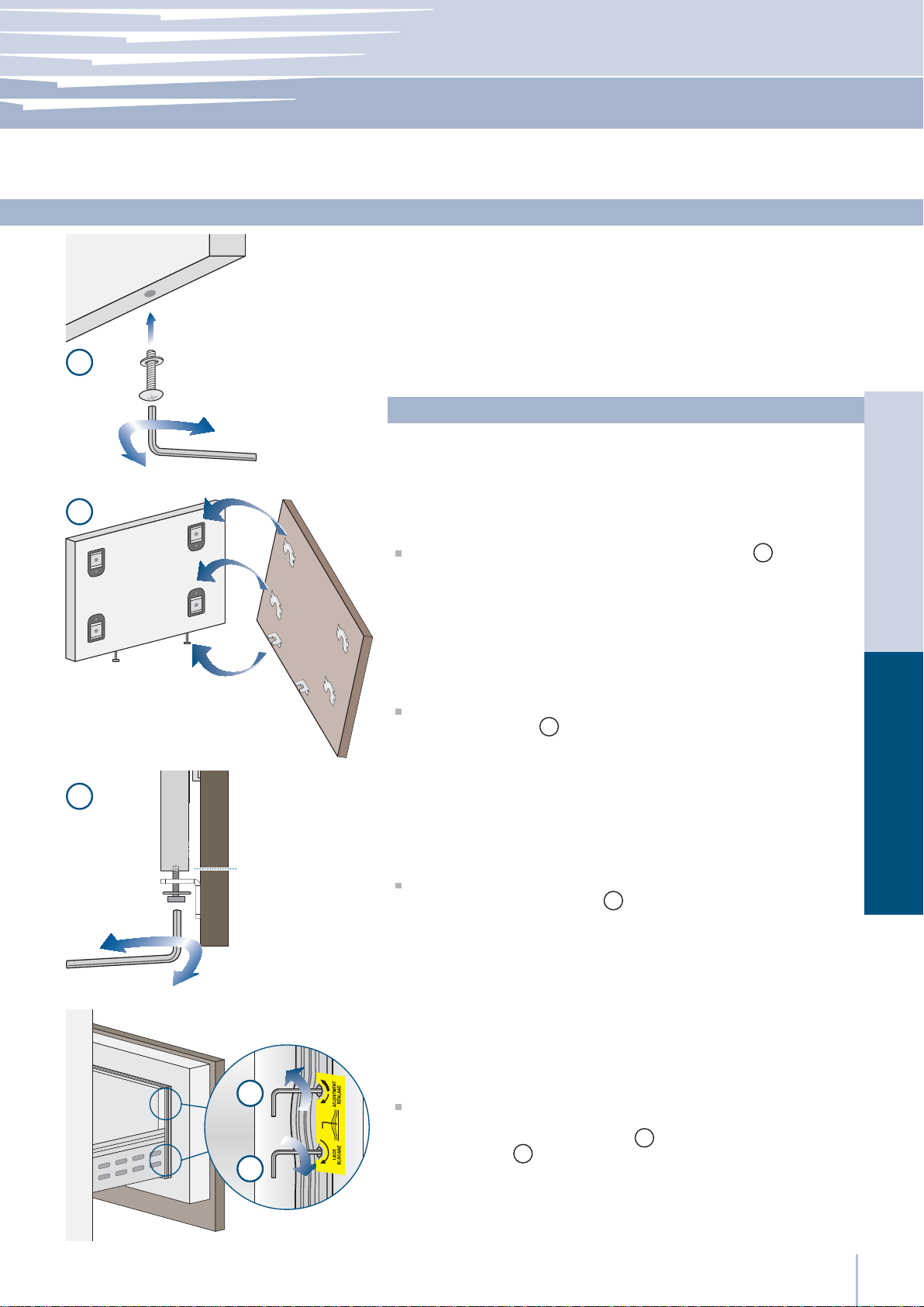
Fixation des panneaux à la porte et au Grand bac: Sèrie Integrated
Aprés avoir appliqué les pattes de À xation et les équerres aux panne-
aux, commencer l’installation par le tiroir du bas.
1
Intervenir de la manière suivante:
Notice d’Installation
Série: Integrated
2
Serrer les vis que partiellement aux À xations inférieures 1.
Fixer le panneau aux support du tiroir à partir des crans de la partie
inférieure de réglage 2
EnglishFrançais
3
À ce point il est possible de régler la hauteur du panneau avec les
crans interieurs pour s’aligner,
tenant la vis un peu desserée, déplacer à droite ou à gauche le panneau pour le centrer au panneau de la porte ou au reste des meubles
de la cuisine.
en serrant ou déssérant la vis. En
3
4
Alignement en profondeur en travaillant de l’intérieur du tiroir et
après avoir soulevé le joint magnétique, rapprocher ou éloigner le
panneau du tiroir à travers les trous 4 puis À xer le panneau toujours
à travers les trous 5.
5
www.fhiaba.com · www.thevettagroup.com
23
Page 60
Série: Integrated
Accrocher le panneau aux dispositifs de À xation en insérant dans les
crans d’alignement supérieurs 6.
6
Il est possible d’ajuster l’alignement du panneau par rapport aux
meubles adjacents à l’aide des pattes et des équerres d’alignement
et 8.
7
7
Alignement vertical: soulever ou abaisser le panneau 9 en vissant
ou en dévissant la vis à l’équerre.
8
9
Alignement en profondeur en travaillant de l’intérieur de la porte
à après avoir soulevé le joint magnétique, rapprocher ou éloigner le
panneau à sa place toutjours à travers les trous
au à sa place toujours à travers les trous
11
puis À xer le panne-
10
.
10
www.fhiaba.com · www.thevettagroup.com
24
11
Page 61
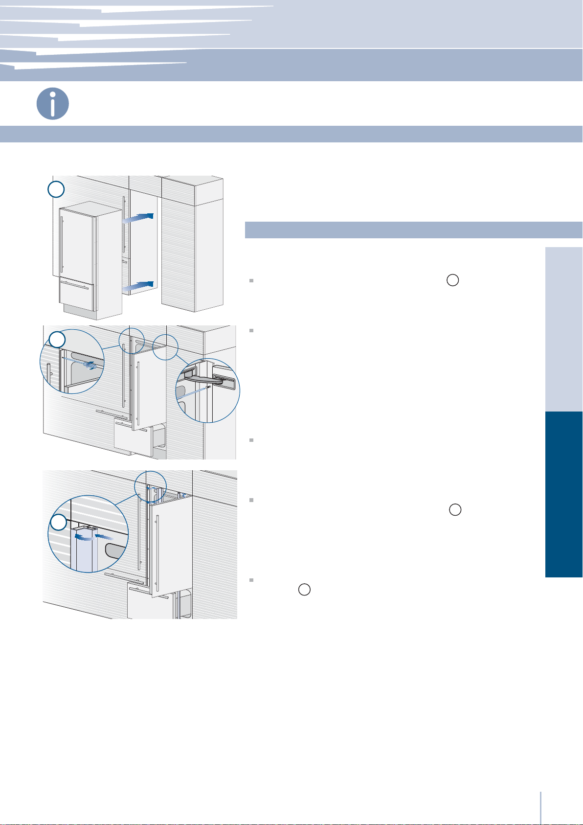
Notice d’Installation
IMPORTANT: Les instructions suivantes pour l’installation s’appliquent à tous les modèles Fhiaba.
Installation dans la niche
Série: tous
Encastrement appareil unique
Des proÀ ls en aluminium peuvent être utilisés pour fermer les espaces
entre l’appareil et les meubles adjacents ou un autre appareil juxtaposé à celui-ci.
1
Intervenir de la manière suivante:
Pousser l’appareil dans la niche d’installation 1.
Si l’appareil doit être installé dans une niche ou à l’intérieur d’une
2
structure fermée, il sera nécessaire de prévoir une cheminée de ventilation à l’arrière de la niche pour garantir une ventilation adèquate. Un écart de 5 mm (1/4”) est sufÀ sant pour éviter tout surchauffe-
ment. Assemblez toujours les panneaux frontaux à la porte et aux tiroirs
avant de placer l’appareil dans sa position déÀ nitive dans la niche ou
la structure.
VériÀ er que les pieds et les roues arrière soient à niveau avant d’en-
castrer l’appareil.
EnglishFrançais
Fixer l’appareil aux meubles adjacents en vissant à ces derniers les
deux proÀ ls latéraux, déjà montés sur l’appareil 2.
3
Pour effectuer facilement l’opération, garder la porte et le grand bac
ouverts.
Monter sur les proÀ ls les corniches de couverture, en les insérant la-
téralement 3 et puis en poussant avec force jusqu’au “clic”.
www.fhiaba.com · www.thevettagroup.com
25
Page 62
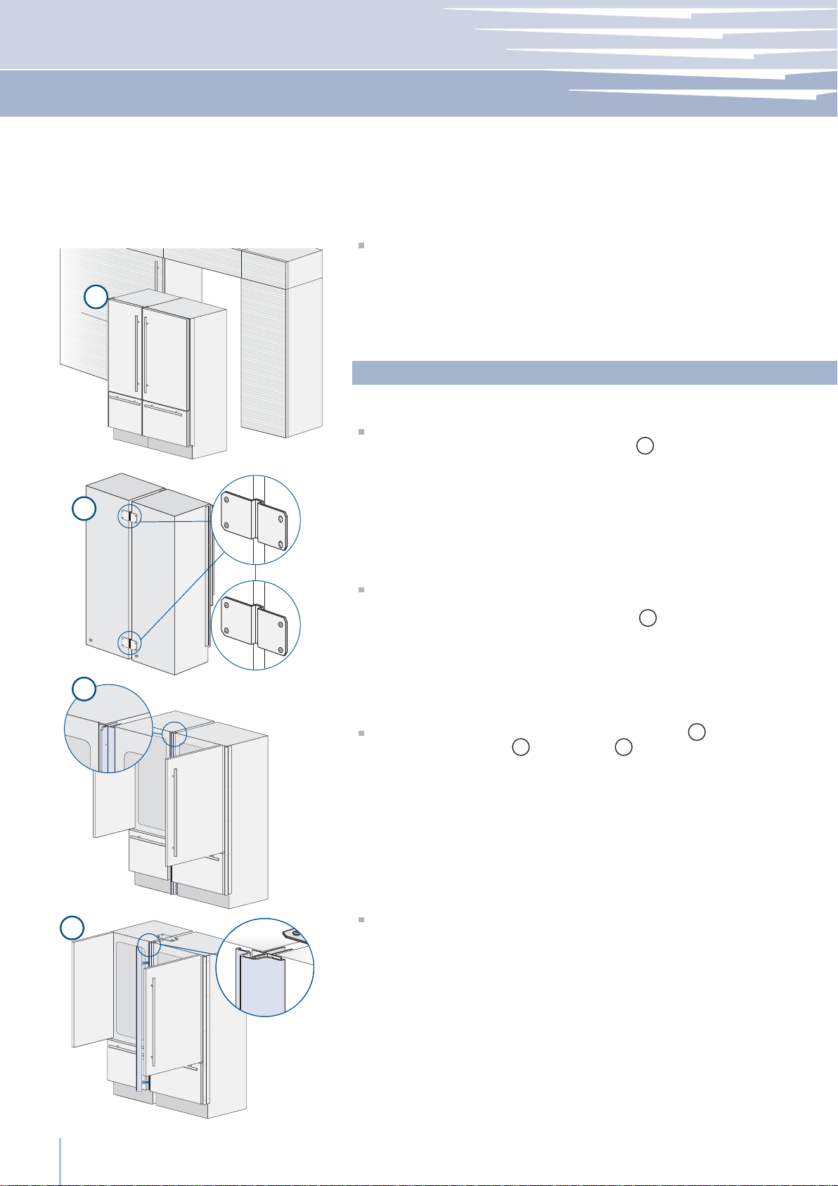
Série: tous
Encastrement combinaison
1
Accessoires nécessaires à commander séparément:
Kit raccordement central (KCCIT/KCCIH)
Des proÀ ls en aluminium peuvent être utilisés pour fermer les espaces
entre l’appareil et les meubles adjacents ou un autre appareil juxtaposé à celui-ci.
Intervenir de la manière suivante:
Positionner les appareils devant la niche en laissant un espace sufÀ sant pour intervenir sur l’arrière des appareils 1.
2
Passer à l’arrière des appareils pour le montage des équerres de
connexion. Fixer un côté de l’équerre supérieure et inférieure, d’abord
sur un des deux appareils et ensuite sur l’autre 2.
3
Visser entre eux les deux proÀ ls avec les rivets fournis 3.
Fixer l’équerre supérieure 4 et l’inférieure 5 d’abord sur un appareil
et puis sur l’autre.
Pour effectuer facilement l’opération, garder la porte et le grand bac
ouverts.
4
Compléter en montant la corniche de couverture centrale en poussant avec force jusqu’au “clic”.
www.fhiaba.com · www.thevettagroup.com
26
Page 63
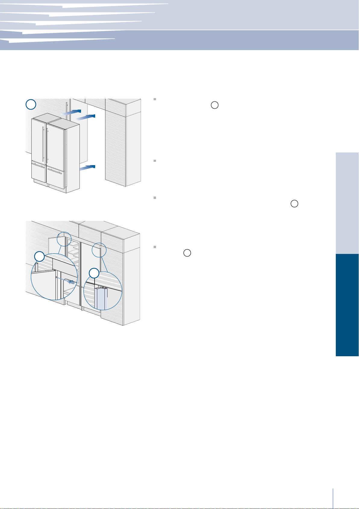
Notice d’Installation
Série: tous
Une fois complétés les passages ci-dessus, poussez les appareils dans
5
leur position déÀ nitive 6.
Il sera nécessaire de prévoir une cheminée de ventilation à l’arrière
de la niche pour garantir une ventilation adèquate. Un écart de 5 mm
est sufÀ sant pour éviter tout surchauffement. Assemblez toujours les
panneaux frontaux à la porte et aux tiroirs avant de placer l’appareil
dans sa position déÀ nitive dans la niche ou la structure.
VériÀ er que les pieds et les roues arrière soient à niveau avant d’en-
castrer l’appareil.
Fixer chaque appareil aux meubles adjacents en vissant à ces derniers les proÀ ls latéraux, déjà montés sur les appareils 7.
Pour effectuer facilement l’opération, garder la porte et le grand bac
ouverts.
Monter sur les proÀ ls les corniches de couverture, en les insérant la-
6
téralement 8 et puis en poussant avec force jusqu’au “clic” (comme
pour l’encastrement de l’appareil unique).
EnglishFrançais
7
www.fhiaba.com · www.thevettagroup.com
27
Page 64
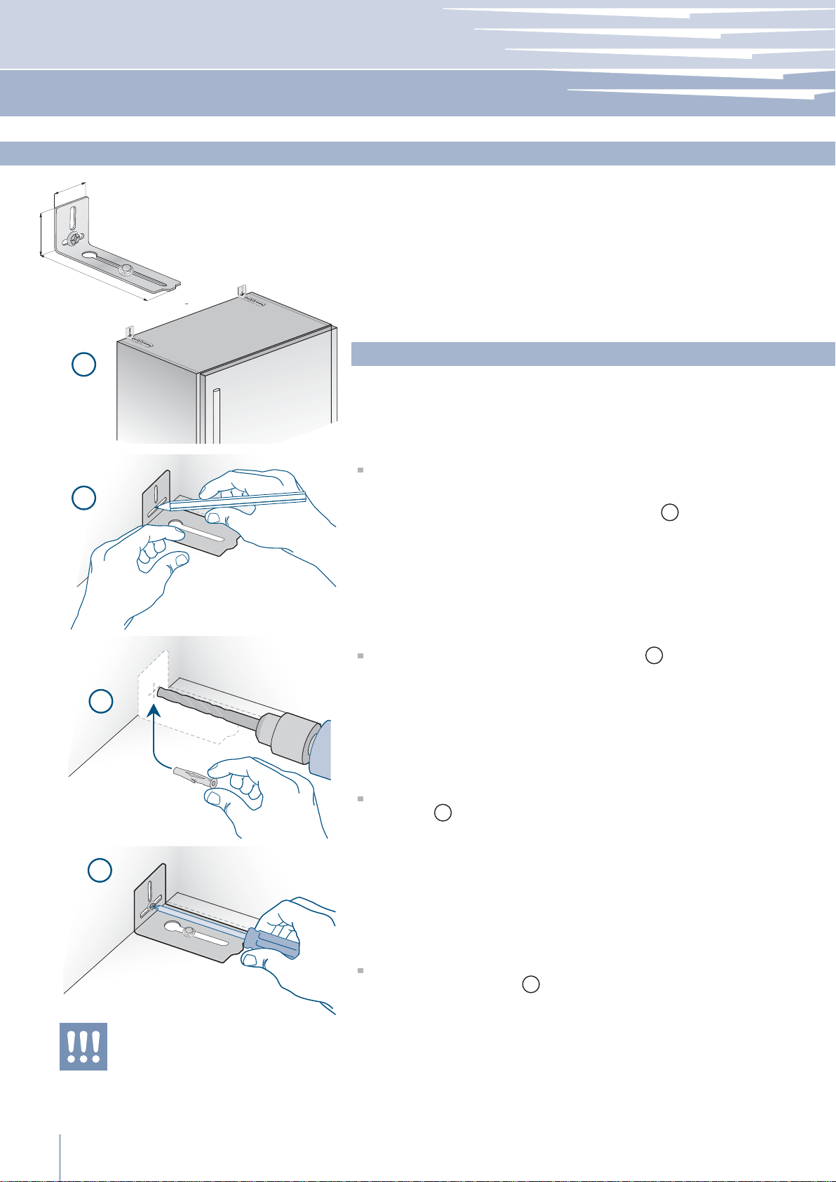
Série: Integrated
Montage de la sécurité anti-renversement
”)
5⁄8
45 (1
”)
3⁄8
2
59 (
152 (6”)
AÀ n d’éviter le risque de renversement de l’appareil lors de l’ouverture
de la porte et des bacs à pleine charge, l’installation de deux équerres qui À xent la partie supérieure de l’appareil au mur est obligatoire.
1
Intervenir de la manière suivante:
Les équerres sont appliquées comme illustré à la À gure en utilisant les
vis et les chevilles fournies.
2
Placer l’équerre sur la partie supérieure de l’appareil en correspondance des trous de À xation et l’approcher au mur 1.
Marquer la position des trous avec un crayon 2.
3
4
AÀ n d’éviter tout risque de renversement de l’ap-
pareil, il est obligatoire de À xer l’appareil au mur
moyennant deux équerres prévues à cet effet.
www.fhiaba.com · www.thevettagroup.com
28
Percer le mur avec une mèche de 8 mm (3/8”) et insérer la vis
tamponnée 3.
Replacer l’équerre et la À xer d’abord sur la partie supérieure du
meuble et, ensuite, au mur 4.
Page 65
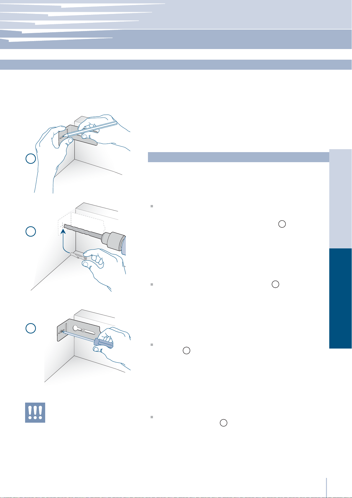
Notice d’Installation
Série: StandPlus/X-Pro
Montage de la sécurité anti-renversement
AÀ n d’éviter le risque de renversement de l’appareil lors de l’ouverture
de la porte et des bacs à pleine charge, l’installation de deux équerres qui À xent la partie supérieure de l’appareil au mur est obligatoire.
1
Intervenir de la manière suivante:
Les équerres sont appliquées comme illustré à la À gure en utilisant les
vis et les chevilles fournies.
Placer l’équerre sur la partie supérieure de l’appareil en correspondance des trous de À xation et l’approcher au mur 1.
EnglishFrançais
2
Marquer la position des trous avec un crayon 2.
3
AÀ n d’éviter tout risque de renversement de
l’appareil, il est obligatoire de À xer l’appa-
reil au mur moyennant deux équerres prévues à cet effet.
Percer le mur avec une mèche de 8 mm (3/8”) et insérer la vis
tamponnée 3.
Replacer l’équerre et la À xer d’abord sur la partie supérieure du
meuble et, ensuite, au mur 4.
www.fhiaba.com · www.thevettagroup.com
29
Page 66
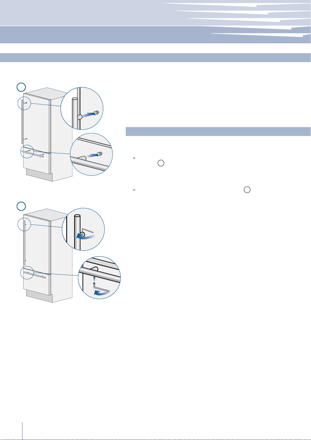
Série: StandPlus/X-Pro
Montage des poignées sur le devant inoxydable
1
Pour À xer les poignées à la porte et au grand bac, intervenir comme
indiqué.
Intervenir de la manière suivante:
Insérer les écarteurs sur les deux goujons présents sur la porte et sur le
grand bac 1.
Visser les vis à six pans présentes dans la poignée 2.
2
Les vis de À xation seront serrées à fond, en utilisant une clé à six pans
de 2,5 mm (1/8”).
www.fhiaba.com · www.thevettagroup.com
30
Page 67
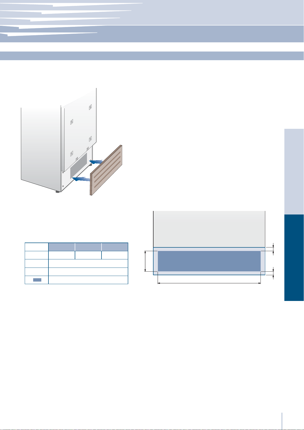
Notice d’Installation
Série: Integrated
Circulation de l’air
Un système à air forcé assure la ventilation à travers la grille positionnée dans la dans la partie inférieure de l’appareil. Si l’aménagement
de la cuisine prévoit une plinthe, cette dernière doit être trouée aÀ n
de garder un niveau d’aréation satisfaisant, comme expliqué dans le
dessin. Les trous peuvent être de toute sorte de forme et dimension, à
condition que la surface totale de la partie trouée est égale au 50%
de la surface de la plinthe.
Dans ce cas, pour permettre une meilleure aération, il est préferable
de retirer la grille frontale de l’ensemble. La grille est accrochée à
l’ensemble avec des plaques magnetiques et peut être facilement
retirée par l’utilisateur À nal, aÀ n d’être nettoyée régulièrement de la
poussière.
Série 36 Série 30 Série 24
A 860 (33 7⁄8”) 740 (29 1⁄8”) 560 (22”)
B
C
> 100 (4”)
10 (3⁄8”)
50%
EnglishFrançais
C
B
C
A
www.fhiaba.com · www.thevettagroup.com
31
Page 68
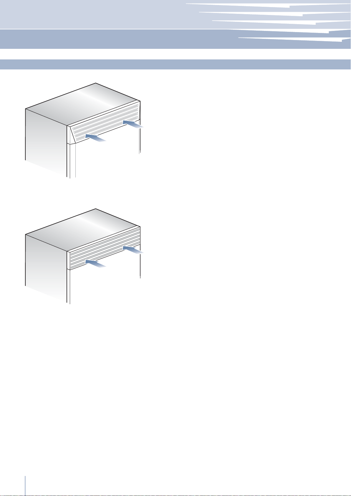
Série: StandPlus/X-Pro
Ventilation
La ventilation est garantie par un système à air forcé à travers une
grille positionnée dans la partie haute de l’appareil.
Cette grille ne doit en aucun cas être couverte par des panneaux ou
autres dispositifs qui pourraient en réduire l’efÀ cacité.
S’il vous plaît se référer à la page 5-6 pour assurer une circulation d’air
correcte.
www.fhiaba.com · www.thevettagroup.com
32
Page 69
Notice d’Installation
Série: tous
Contrôle de À n d’installation mise en marche
Contrôler que les pieds sont correctement installés.
Contrôler que le raccordement à l’installation hydrique ne présente
pas de fuites d’eau et que le robinet de fermeture est facilement accessible.
Contrôler que le branchement électrique soit correctement réalisé
et que la À che et l’interrupteur omnipolaire dédié soient facilement
accessibles.
Contrôler le parfait alignement de l’appareil avec les meubles adjacents.
Contrôler que chaque ruban adhésif ou protection temporaire interne ou externe soit éliminé.
Contrôler la parfaite étanchéité des portes et le coulissement des
bacs et des clayettes.
EnglishFrançais
www.fhiaba.com · www.thevettagroup.com
33
Page 70
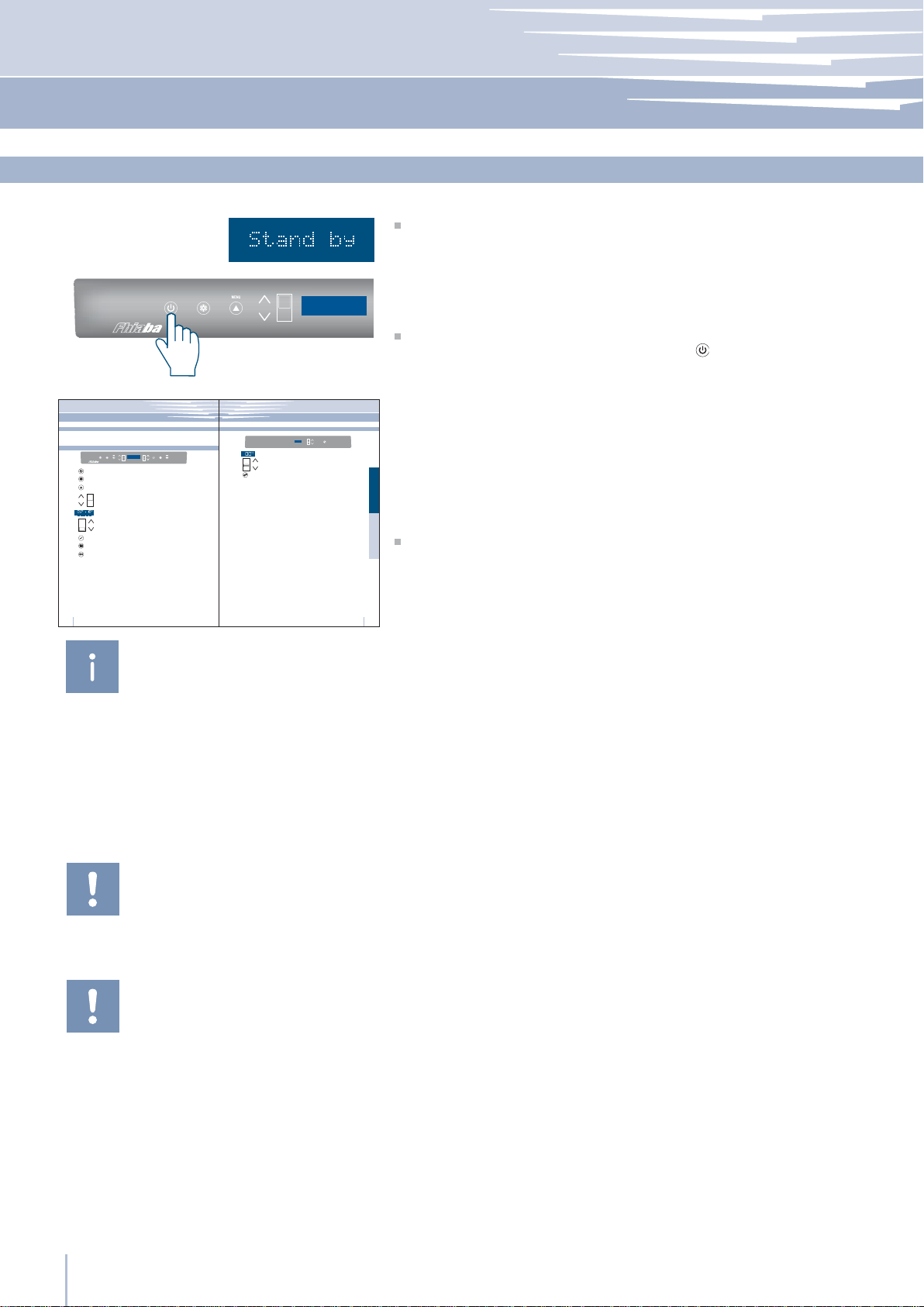
Série: tous
Mise en marche
UNIT
Before starting
3
Electronic Control
3.4
The innovative electronic control system designed by Fhiaba maintains constant temperature in multiple compartments and
displays it on the control panel. It also allows user interaction making it possible to personalize settings of various functions and
to alert the user with sound and/or visual messages should any malfunction occur in the appliance.
FRI
I
N
D
U
T
G
E
1234 5 67 98
1 Unit
2 Fridge
3 Menu
Up/down
4
Fridge
5 Display
Up/Down
6
Freezer
(TriMode)
7 Enter
8 Ice maker
9 Alarm
Main control panel
E
NT
C
E
I
E
A
M
KE
R
R
Switches the appliance (all compartments) between ON and STAND BY
(press for three seconds).
Allows switching on and off of only the refrigerator compartment
(press for three seconds).
Allows access to the appliance function menu
Using the Up and Down buttons, it is possible to change the set temperature of the refrigerator and navigate through the interactive menu.
It shows the temperature of the refrigerator and freezer compartments,
the date and time, Menu functions and visual messages.
By selecting Up/Down the preset temperature can be changed according to the selected function mode (freezer, refrigerator, Crisper-Fresco).
Confirms activation or deactivation of the selections made in the
Menu.
Allows activating or deactivating the automatic ice production.
Blinks to signal user alerts such as door left open, also in combination with
a sound signal which can be deactivated by pressing the button.
FR
IDGE
3.5
11 Display
12 Up/Down
13 Crisper
Before starting
Crisper-Fresco control panel
CRI
P
S
R
E
10 11 12
Shows the temperature of the Crisper-Fresco compartment.
Using the Up and Down buttons, it is possible to change the
temperature set for the Crisper-Fresco compartment.
Allows switching on and off of only the Crisper-Fresco compartment
(press
for three seconds).
Pour mettre en marche l’appareil, brancher la À che au réseau
électrique: lorsque la porte est ouverte, apparaît sur le panneau de
commande le message “Stand-by”, alors que toutes les touches du
panneau sont éteintes.
Pour mettre en marche tous les compartiments de l’appareil, appuyer pendant 3 secondes sur la touche Unit .
Le message “initial test” apparaîtra pendant environ 2 minutes, ensuite
les compresseurs seront actifs jusqu’à attendre la température prévue
en usine par défaut. Veuillez noter que cette opération pourrait durer
plusieurs heures.
3
3.6
Si l’appareil est fourni avec un appareil à glaçons avant de le mettre
en marche pour la première fois, veuillez vous assurer que la cartouche du À ltre pour l’eau a bien été installée et effectuez un remplissage
du circuit hydraulique.
EnglishFrançais
Pour toute autre information concernant le fonctionnement de
l’appareil, se référer au Mode d’emploi.
www.fhiaba.com ∙ www.thevettagroup.com
8
www.fhiaba.com ∙ www.thevettagroup.com
9
Si lors de la première mise en marche, n’apparaît pas le message Stand-by, mais apparaissent
Fridge too warm, Fresco too warm, Freezer too
warm ou signaux sonores, cela signiÀ e que l’ap-
pareil a déjà commencé la procédure de refroidissement.
Dans ce cas désactiver les éventuels messages
sonores en efÁ eurant la touche Alarm, refermer la
porte et attendre que les températures programmées soient atteintes.
Il faut laisser l’unité atteindre la température de
fonctionnement vide et avec la porte et un tiroir fermé avant que les aliments sont stockés à l’intérieur.
Sur les modèles avec un compartiment dédié
Fresco, le compartiment Fresco refroidit à la température de consigne (par défaut 0°C / 32°F) avant
la commutation du système de refroidissement du
compartiment de réfrigération principale. Dans ce
cas désactiver les éventuels messages sonores en
efÁ eurant la touche Alarm, refermer la porte et at-
tendre que les températures programmées soient
atteintes.
www.fhiaba.com · www.thevettagroup.com
34
Page 71

Page 72

Page 73
27-11-2014
EN
FR
Fhiaba srl is constantly researching new way to improve the features and the design of their products, therefore models
are often upgraded and reviewed.
Fhiaba est constamment à la recherche de nouvelles solutions pour améliorer les caractéristiques et le design de ses
propres produits et se réserve le droit d’apporter continuellement des modiÀ cations à ses modèles.
Page 74

B09000704 UL
www.fhiaba.com
Info Line
800 - Fhiaba . (800-344222)
 Loading...