

FGT® Model TMFC Mass Flow Controller/Meter
r
m
Installation and Operation Manual
U-TMFC--EN
Part number:0912TWAD
October,2009
FGT® Model TMFC Mass Flow Controller/Mete
Installation and Operation Manual
U-TMFC--EN
Part number:0912TWAD
October,2009
Essential Instructions
Read this page before proceeding!
FGT designs, manufactures and tests its products to meet many national and international standards. Because these instruments are
sophisticated technical products, you must properly install, use and maintain them to ensure they continue to operate within their normal
specifications. The following instructions must be adhered to and integrated into your safety program when installing, using and maintaining
Mass Flow Controller
TMFC Series
Installation and Operation Manual
FGT products.
z Read all instructions prior to installing, operating and servicing the products. If this instruction manual is not the correct manual,
telephone 886-6-2632460 and the requested manual will be provided. Save this instruction manual for future reference.
z If you do not understand any of the instructions, contact your FGT representative for clarification.
z Follow all warnings, cautions and instruction marked on and supplied with the products.
z Inform and educate your personnel in the proper installation, operation and maintenance of the product.
z Install your equipment as specified in the installation instructions of the appropriate instruction manual and per applicable local and
national codes. Connect all products to the proper electrical and pressure sources.
z To ensure proper performance, use qualified personnel to install, operate update, program and maintain the products.
z When replacement parts are required, ensure that qualified people use replacement parts specified by FGT. Unauthorized parts
and procedures can affect the product’s performance and place the safe operation of your process at risk. Look-alike substitutions
may result inn fire, electrical hazards or improper operation.
z Ensure that all equipment doors are closed and protective covers are in place, except when maintenance is being performed by
qualified persons, to prevent electrical shock and personal injury.
CAUTION
This Instrument contains electronic components that are susceptible to damage by static electricity. Proper handling
procedures must be observed during the removal, Installation or other handling or internal circuit boards or devices.,
www.fgttw.com
First General Technology Inc.
-1-
Handing Procedure
4. Power to unit must be removed.
5. Personnel must be grounded, via a wrist strap or other safe, suitable means before any printed circuit card or other internal
device is installed, removed or adjusted.
6. Printed circuit cards must be transported in a conductive bag or other conductive container. Boards must not be removed from
protective enclosure until immediately before installation. Removed boards must immediately be placed in protective container
for transport, storage or return to factory.
Comments
This instrument is not unique in its content of ESD (electrostatic discharge) sensitive components. Most modern electronic designs contain
components that utilize metal oxide technology (NMOS, CMOS, etc,) Experience has proven that even small amounts of static electricity
can damage or destroy these devices. Damaged components even though they appear to function properly, exhibit early failure.
www.fgttw.co
-2-
FGT® Model TMFC Mass Flow Controller/Meter
r
m
Installation and Operation Manual
Part number:0912TWAD
U-TMFC--EN
October,2009
CONTENTS:
1.Specifications------------------------------------------------------------------------------- 4
1-1.Specifications------------------------------------------------------------------------- 4
Page
Installation and Operation Manual
Part number:0912TWAD
FGT® Model TMFC Mass Flow Controller/Mete
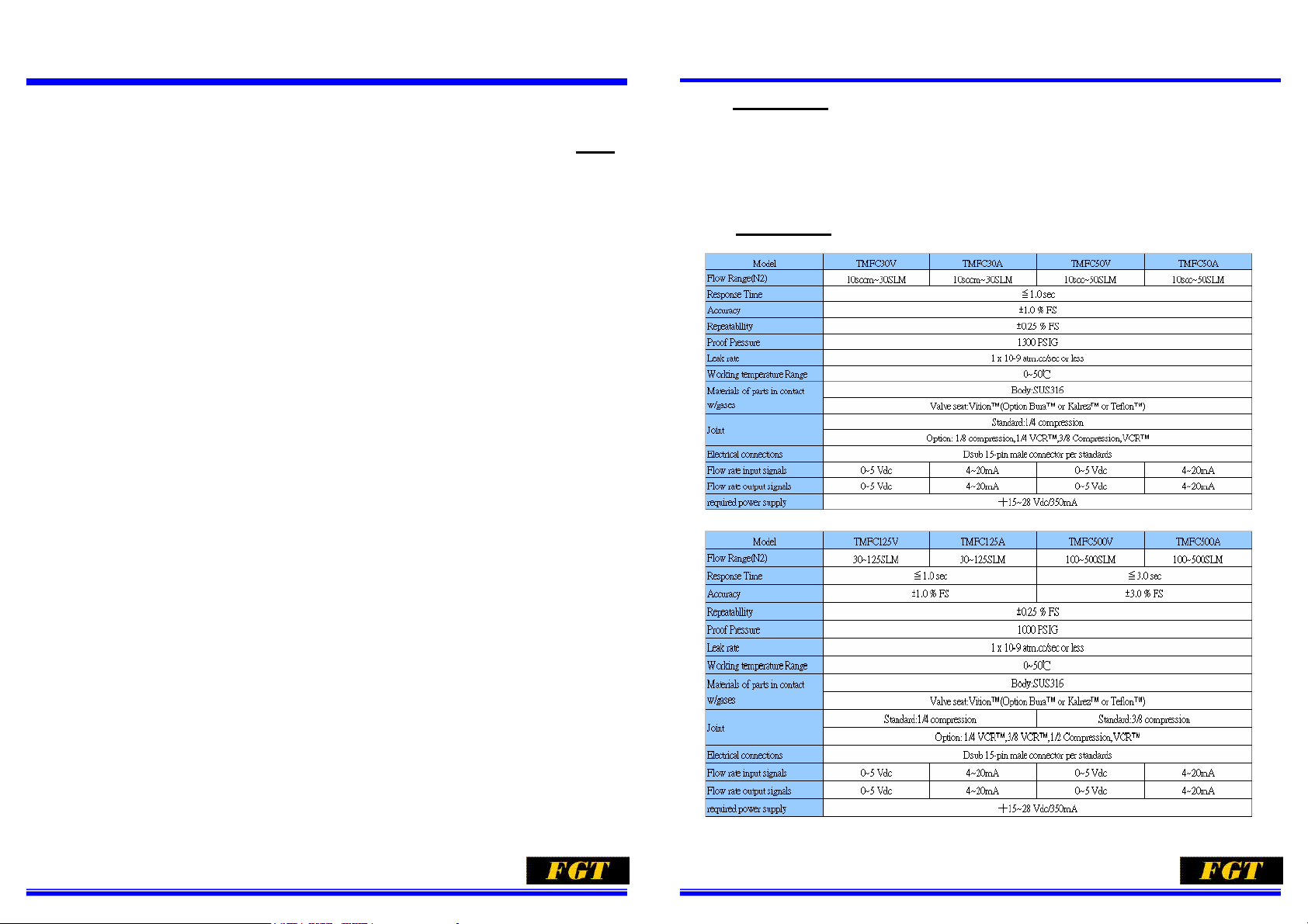
2. Specifications
Model TMFC series Mass Flow controller accurately measures and controls gas flow.
This instrument is used for flow control in a wide range of application including various
analyzers, combustion, and biotechnology.
U-TMFC--EN
October,2009
1-2.Unit of Flow--------------------------------------------------------------------------- 5
2.Principle of Operation-------------------------------------------------------------------- 6
3.Standard configuration and Wiring Connection------------------------------------ 7
3-1.Stadard Configuration-------------------------------------------------------------- 7
3-2.Electric connection Diagram and Wiring Connection------------------------ 8
4.Installation and Piping-------------------------------------------------------------------- 11
4-1.Storage and Application environment------------------------------------------ 11
4-2.Piping System Washing------------------------------------------------------------ 12
4-3.In-line Filter---------------------------------------------------------------------------- 12
4-4.Combined Use of The Set-point Valve------------------------------------------ 13
4-5.Use of The conversion Tables ---------------------------------------------------- 14
4-6 Gas Connection---------------------------------------------------------------------- 18
4-7.Installation----------------------------------------------------------------------------- 18
5.Operational Procedure------------------------------------------------------------------- 19
6.Troubleshooting----------------------------------------------------------------------------- 20
7.Dimensions---------------------------------------------------------------------------------- 22
1-1. Specifications
8.Product Warranty--------------------------------------------------------------------------- 23
www.fgttw.com
-3-
www.fgttw.co
-4-
FGT® Model TMFC Mass Flow Controller/Meter
r
m
Installation and Operation Manual
Part number:0912TWAD
U-TMFC--EN
October,2009
1-2. Unit of Flow
Our mass flow controller is based on the SEMIIE12-91(semi-standard).
The applied unit is SLM (Standard Liter per Minute) or SCCM (Standard Cubic per
Minute). The status of this gas is the same as the reference(normal) conditions of 0℃,
101.325kPa(abs). If the applied flow unit and definition thereon differ, inquire us of it or
give us your instructions. If the unit you require is a SI unit or unit approved by the current
measuring law, we will make a production on the basis of the unit you require.
FGT® Model TMFC Mass Flow Controller/Mete
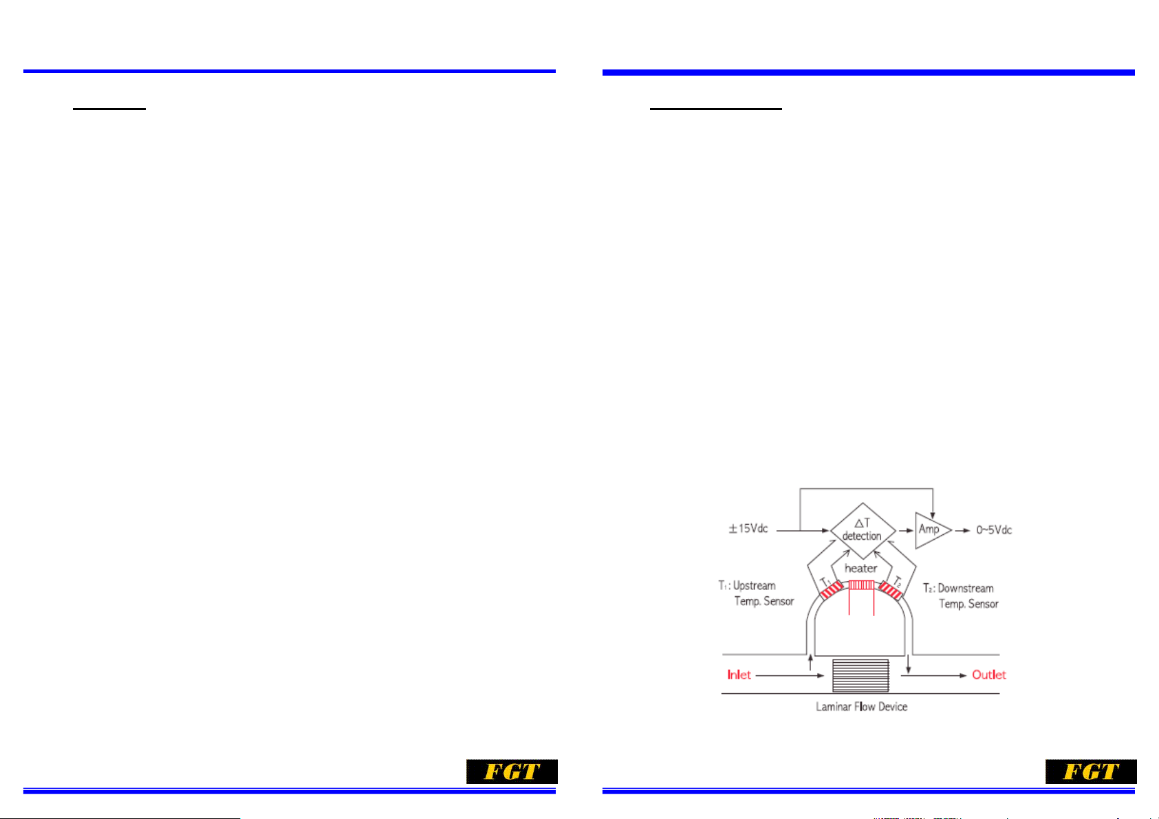
2. Principle of Operation
The detection sensor for Mass Flow is wound
thermo-resistance wires on the outsides of the
two positions (upstream and downstream) of the
metal tubing. Flowing a certain quantity of current
into its wires and self-heating them allow the
thermo-resistance wires on the two positions to
have a balance at the same temperature during
gas with no flow in the metal tubing. When gas
flows in this metal tubing, the thermo-resistance
wires on the up-per flow side is deprived of heat
by the gas, thereby lowering the temperature.
The downstream is conveyed the heat of the
upstream. This raises the temperature and
breaks the initial balance, thus also causing a
difference between the resistances. The
temperature difference of theses position grows
in proportion to the gas flow amount and a
volume of the heat capacity specified with the
specific gravity and specific heat determines the
ratio of the temperature difference change. The
change of the gas flow amount is caught of the
resistance value. Thus detecting the Mass Flow.
(=Principal of the thermal flow sensor).
Installation and Operation Manual
Part number:0912TWAD
The change of the Mass Flow is represented as
a change of the voltage signal by the electronic
circuit, through utilization of this principal.
Selecting-mounting a bypass capillary for
making the flow detecting sensor bypass the
flow limits the gas flow in this section, thus
enabling the flow rating to be determined. In
addition, mount a comparative control circuit
onto the combination of the flow detection
sensor and control valve for this Mass Flow,
thereby providing it with signals for setting the
flow detection sensor and flow. The
comparative control circuit compares these two
signals. Then if the output signal is smaller than
the setting signal, turn the opening of the control
valve greater, thus changing the current added
to the solenoid valve, the standard valve is of
normal closing type, with the power not-being
On, the flow route is closed.
U-TMFC--EN
October,2009
www.fgttw.com
-5-
www.fgttw.co
-6-
FGT® Model TMFC Mass Flow Controller/Meter
r
m
Installation and Operation Manual
U-TMFC--EN
Part number:0912TWAD
October,2009
FGT® Model TMFC Mass Flow Controller/Mete
Installation and Operation Manual
U-TMFC--EN
Part number:0912TWAD
October,2009
3.. Standard configuration and Wiring Connection
3-1. Standard Configuration
WARNING
Do not operate this instrument in excess of the specifications. Failure to heed this
warning may result in serious personal injury and / or damage to the equipment
Standard Ranges Output Signal(Fig-4)
z 10 sccm to 500 slpm (nitrogen equivalent) z 0~5 Vdc into 2kΩor greater. Maximum
ripple 3 mV. Jumper selectable 4~20 mA.
Refer to Fig-4 for maximum total loop
resistance.
Accuracy 5 Volt reference Output
z ±1.0% scale including linearity at calibration
conditions. ±1.50% full scale including
linearity for floe ranges greater than 20 slpm
z 5 V ±0.2%.Maximum load 1KΩ
Repeatability Command Input(Fig-2/Fig-3)
z 0.25% of rate z Jumper Selectable: 0~5 Vdc, Input resistance
200KΩ or 4~20 mA, Input resistance 75Ω
Response Time Leak Integrity
z Less than 3 seconds response to within 2%
full scale final value with 0 to 100%
command step.
z 1x 10
-9
Atm. CC/sec helium
Power Requirements Control Range
z +15 ~ + 28 Vdc 350mA z 50 to 1
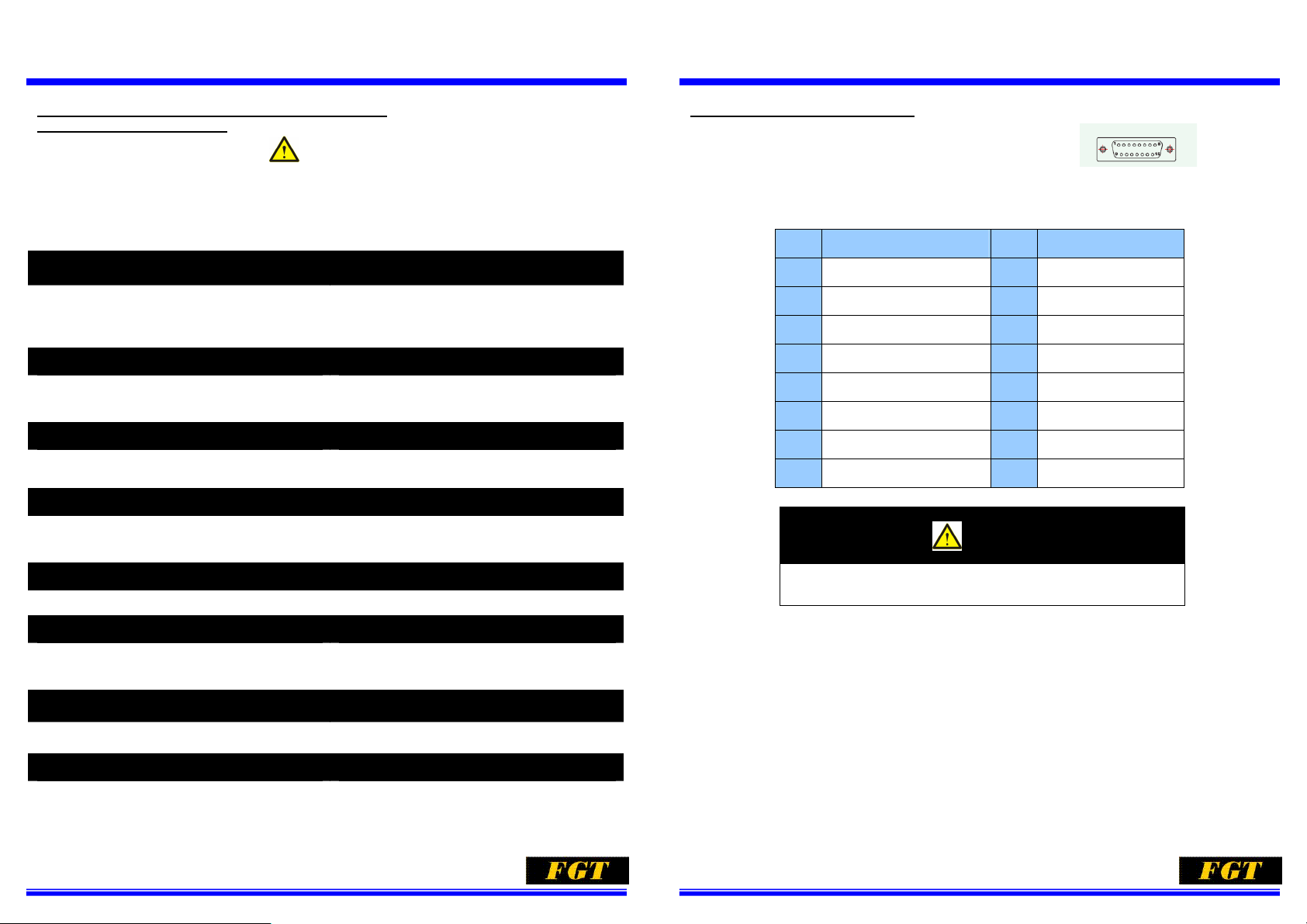
3-2. Electric connection Diagram
Electrical Connection(Fig-1)
D-type Connections Pin out
Pin Assignment of Dsub 15-Pin Connector per Standards
Pin No. Signal Pin No. Signal
1 COM ground 9 Power Source COM
2 Flow output 0~5VDC 10 Flow output Ground
3 No used 11 +5 Vdc reference output
4 Flow output 4~20mA 12 Valve Override
5 +15~28 VDC Power Source 13 No used
6 -15 VDC Power source 14 Chassis ground
7 Current flow input COM 15 No used
8 Voltage flow Input COM
*Because a differential input system is used for the products, pin 2&8 for TMFC30V and pin
4&7 for TMFC30A choice one kind of signal input/output to use.
Fig-1
CAUTION
Ambient temperature Limits Mechanical Connection (Fig-5)
z Operating:5 ~ 65 (40 to 150℃ ℉)
z No-Operating:-25 to 100 (℃ -13 to 212℉)
z Range. Consult factory for details.
z Interchangeable with most popular mass
flow controller .Fig-5
Working Pressure Electrical Connection(Fig-1)
z 1300/1000 psi maximum z D-type:Dsub 15-pin connector, Mating
connector supplier.
Allowable Differential Pressure Mounting Attitude Sensitivity
z 5 psi minimum,50 psi maximum. Higher
differential pressures are allowable
z ±0..5% maximum full scale deviation after
re-zeroing.
www.fgttw.com
-7-
www.fgttw.co
-8-

FGT® Model TMFC Mass Flow Controller/Meter
r
m
Installation and Operation Manual
U-TMFC--EN
Part number:0912TWAD
October,2009
FGT® Model TMFC Mass Flow Controller/Mete
Installation and Operation Manual
U-TMFC--EN
Part number:0912TWAD
October,2009
Command Input(Fig-2/Fig-3)
For Signal I/O:0~5Vdc in sub-code of “V” Type
Fig-2
For Signal I/O:4~20mAdc in sub-code of “A” Type
Output Signal(Fig-4)
TMFC-Series PCB board Jumper Location & Function
www.fgttw.com
Fig-3
Fig-4
-9-
www.fgttw.co
-10-

FGT® Model TMFC Mass Flow Controller/Meter
r
m
Installation and Operation Manual
U-TMFC--EN
Part number:0912TWAD
October,2009
FGT® Model TMFC Mass Flow Controller/Mete
Installation and Operation Manual
U-TMFC--EN
Part number:0912TWAD
October,2009
4.Installation and Piping
For design and piping construction of the instrument and piping of the system including the
mass flow controller, fully read the following matter and perform job with particular attention
being parid.
4-1.Storage and Application environment
Applying this instrument near the equipment such as high frequency induction
furnace or in the place in which various power systems are concentrated may easily
intrude noise in to Mass Flow Controller, thereby interfering normal operation.
Avoid storage or application outdoor in direct contact with wind-rain or dusts. Avoid
application under the environment in which drops of water directly fall, or dusts have
been accumulated, or in the atmosphere having a high temperature or corrosive
gases. The application in there places may deteriorate or corrode the electronic parts
or cause a connection fault of the cable connection unit.
Avoid storage or application in a place in which the ambient temperature exceeds
65℃ or vibrations occur. When using the controller with gas being actually flowed,
the gas temperature and ambient temperature must be within 5~65 ℃.
Application out of this range may cause damages of the performance. So pay
particular attention to it.
CAUTION: When installing this instrument, avoid the environment in which an
ambient noise generating source exists, and drops of water or dusts
have accumulated, or the atmosphere in which a high temperature
4-2.Washing of The Piping System
Fully internally wash the pipes and applications ( such as the pressure regulator,
pressure gauge and stop valve) used for piping system before the application thereof. Mixing of dusts, rusts, oil and water makes and intrusion of their substances into
the mass flow controller, thus causing and internal clogging, deterioration in
performance and erroneous operation..
CAUTION: Never wash the piping system after incorporation of this instrument.
Ignoring it may cause a critical malfunction.
4-3.In-line Filter
It is recommend that an In-Line be installed upstream from the controller to prevent
the possibility of any foreign material entering the flow sensor or control valve. The
filtering element should be replaced periodically or ultrasonically cleaned.
When applying the air fed out of the compressor or fan, a large quantity of oil mist or
drops of water may intrude. So mount an oil filter or water-eliminating filter on the
front stage.
Recommended filter size
Maximum flow Filter size
10~30SLM
Up to 500SLM
.
15μ
30μ
www.fgttw.com
and corrosive gas exist. Ignoring it may cause a critical malfunction.
-11-
www.fgttw.co
-12-

FGT® Model TMFC Mass Flow Controller/Meter
r
m
Installation and Operation Manual
U-TMFC--EN
Part number:0912TWAD
October,2009
FGT® Model TMFC Mass Flow Controller/Mete
Installation and Operation Manual
U-TMFC--EN
Part number:0912TWAD
October,2009
4-4.Combined Use of The Set-point Valve
z Valve Override:
z Set-point(Command):
z Low Command Valve Inhibit:
z Removable Cleanable Sensor:
z Output Limiting:
Permits the user to fully open and
close the control valve independent of
the Set-point(Command) setting.
Permits the user to program the mass
flow controller with an external
0~5Vdc or 4~20mAdc signal.
(Auto Shutoff) prevents the valve
from opening whenever the set-point
is less than 2% of full scale.
Permits the user to clean or replace
the sensor
Prevents possible damage to delicate
data acquisition devices by limiting
the output to -0.7~+6.8 Vdc on the
voltage signal output and 0~26 mAdc
on the current output
4-5.Use of The conversion Tables
When operating Model TMFC-Series Mass Flow controller correctly, design the
piping system so that the pressure difference between the inlet and outlet. If a mass
flow controller is operated on a gas other than the gas it was calibrated with, a scale
shift will occur in the relationship between the output signal and the mass flow rate.
This is due to the difference in heat capacities between the two gases. This scale
shift can be approximated by using the ratio of the molar specific heat of the two
gases. Or sensor conversion factor. A list of sensor conversion factors is given in
Table 4-1 to change to a new gas. Multiply the output reading by the ratio of the gas
factor for the desired gas to the gas factor for the calibration gas.
It is generally accepted that the mass flow rate derived form this equation is only
accurate to ± 5%. The sensor conversion factors given in Table 4-1 are calculated
based on a gas temperature of 21℃ and pressure of one Atmosphere. The specific
heat of most gases are not strongly pressure and temperature dependent, however
gas conditions that vary widely from these reference conditions may cause an
additional error due to the change in specific heat due to temperature or pressure.
Actual Gas Flow and Operational Pressure Calculated
www.fgttw.com
-13-
www.fgttw.co
-14-

FGT® Model TMFC Mass Flow Controller/Meter
r
m
Installation and Operation Manual
U-TMFC--EN
Part number:0912TWAD
October,2009
FGT® Model TMFC Mass Flow Controller/Mete
Installation and Operation Manual
U-TMFC--EN
Part number:0912TWAD
October,2009
Table 4-1 Conversion Factors(Nitrogen Base)
Table 4-1 Conversion Factors(Nitrogen Base) Continued
www.fgttw.com
-15-
www.fgttw.co
-16-

FGT® Model TMFC Mass Flow Controller/Meter
r
m
Installation and Operation Manual
U-TMFC--EN
Part number:0912TWAD
October,2009
FGT® Model TMFC Mass Flow Controller/Mete
Installation and Operation Manual
U-TMFC--EN
Part number:0912TWAD
October,2009
Table 4-1 Conversion Factors(Nitrogen Base) Continued
4-6.Gas Connection
The standard joints of the TMFC30/50/125-Series Mass Flow Controller are 1/4"
Compression (Swagelok™) or the equivalent on both of the inlet and outlet.
The standard joints of the TMFC50-Series Mass Flow Controller are 3/8" Compression
(Swagelok™) or the equivalent on both of the inlet and outlet
.
4-7.Installation
When designing the piping system employing the Mass Flow Controller, pay
particular attention to that this instrument may have to be removed for maintenance
jobs such as inspection and disassembling washing. Take into full consideration the
arrangement having a space enabling easy removing and reinstallation piping jobs.
During installing this instrument, pay particular attention so that no foreign matters
intrude from the inlet or outlet. Hold attaching the protective caps on the both ends
until the installation.
【Installation procedure】
E. Install Model TMFC-Series Mass Flow Controller in a clean-dried place in which
no impacts and vibration occur.
F. Secure a sufficient space allowing span or zero-point adjustments.
G. Perform piping so that it can be easily removed for request for maintenance
service to us.
CAUTION: Applying toxic gas may cause a contamination or corrosion in
the Mass Flow Controller due to a piping leak or improper
purging. Before the application, fully check to ensure that no
www.fgttw.com
leaks exist in the piping, and perform purging with dried N
gas.
2
H. There exist no limits for instillation posture. However, apply Model
TMFC-Series Mass Flow Controller at the physically no forcible status. Install it
levelly. In the case of other installation postures, perform zero-point adjustment
after the warming-up. When installing Model TMFC-Series Controller, existence
of an angle piping just in front of the controller worsens the accuracy a little.
-17-
www.fgttw.co
-18-

FGT® Model TMFC Mass Flow Controller/Meter
r
m
Installation and Operation Manual
U-TMFC--EN
Part number:0912TWAD
October,2009
FGT® Model TMFC Mass Flow Controller/Mete
Installation and Operation Manual
U-TMFC--EN
Part number:0912TWAD
October,2009
5.Operation Procedure
z Check to ensure that the piping system connection, cable connection and
wirings are correct.
z Securely close the mass flow controller with the solenoid valve and manual
stop valve so that gas will not flow into there.
z Turn ON the power switch and perform warming-up at least for 15 minutes.
This is intended to make thermal and electric balances of the sensor, thus
creating the stable status.
z When no gas flow, the warming-up is sufficiently conducted and the flow
instruction output gets stable, once clockwise turn the knob on the upper
portion of the mass flow controller with a small female driver so that the
indicated valve changes by around 20% full scale and the output changes by
around 1 V or 4 mAdc. Next, counterclockwise turn it so that the indicated value
gets 0% or 0 V(4 mAdc) . For the adjustment mentioned-above, be sure to
make a zero-point adjustment from the plus side so that the indicated value or
output gets a minus value.
z If a compensation for errors between our reference calibrator and reference
flow meter or a span periodical calibration is required, perform calibration in the
following procedure. Ordinarily the calibration is not required. If you don’t have
a reference flow meter, never move the span pot.
【Span calibration procedure】
Connect a reference flow meter to the gas outlet side of the main machine.
Add a gas pressure within the range of the applied pressure to the inlet side
and set the flow at 100% (5 Vdc or 20 mAdc) full scale. After the indicated
value gets stable at its status, measure the flow. Turn the span pot so that the
indication of the flow meter gets a full-scale flow.
It may take times until the flow gets completely stable. So if the span pot was
operated intentionally, waiting for about 5 minutes until measurement of the
flow leads to a calibration with a higher accuracy.
6.Troubleshooting
6.1 Troubleshooting and actions
for quality assurance, and cautions for maintenance
Trouble Possible Cause Check/corrective Actions
Actual flow overshoots set-point by
more than 5% full scale.
Output stays at 0 Volts regardless
of command and there is no flow
through the controller
Output signal stays at +6.8V
regardless of command and there
is flow through the controller.
Output signal follows set-point at
higher commands but will not go to
zero.
Output signal follows set-point at
lower commands but does not
reach full scale
Partially clogged valve Disassemble and repair control valve.
Anticipate potentiometer out of adjustment. Adjust anticipate potentiometer.
Clogged Sensor.
Clogged Controller Valve
- 15 Volts applied to the valve override input
Defective printed circuit board Replace printed circuit board.
Valve stuck open or leaky Clean and /or adjust valve.
+15 V applied to the valve override input.
Detective printed circuit board Replace printed circuit board.
Command input floating
Leaky control valve Disassemble and repair valve.
Excessive resistance in valve voltage
Insufficient inlet pressure or pressure drop.
Clean sensor. Refer to Fig-1&Fig-2&Fig-3
to cleaning.
Check TP3 with the command valve at
100%. If the voltage is more negative than
-11V for NC Valve or +11V for NO Valve,
disassemble and repair the controller
valve.
Check valve override input. For terminal
assignments.
Check the valve override terminal. Refer to
Fig-1&Fig-2&Fig-3 for terminals
assignments.
Connect command signal. Refer to
Fig-1&Fig-2&-Fig-3 for terminal
assignments.
Reduce wiring resistance or re-configure
controller for “External Valve Return”.
Refer to Fig-1&Fig-2&Fig-3
Adjust pressure, inspect the filters and
clear/replace as necessary.
www.fgttw.com
Valve out of adjustment Adjust valve.
Valve guide spring failure Controller oscillates(see bellow) Clean sensor, Contact to us
Controller grossly out of calibration.
Flow is higher than desired
Controller oscillates
Partially clogged restrictor. Replace restrictor
Pressure drop or inlet pressure excessive
Valve out of adjustment Adjust valve. Or contact to us.
Faulty pressure regulator Check regulator output.
Defective printed circuit board Replace printed circuit board. Contact to
Adjust pressures.
us
-19-
www.fgttw.co
-20-

FGT® Model TMFC Mass Flow Controller/Meter
r
m
Installation and Operation Manual
U-TMFC--EN
Part number:0912TWAD
October,2009
FGT® Model TMFC Mass Flow Controller/Mete
Installation and Operation Manual
U-TMFC--EN
Part number:0912TWAD
October,2009
6.2 Cautions for maintenance
6-2-1.Zero-point and span calibrations
I
f you have a reference flow meter, perform both adjustment and calibration of the
zero-point and span. If you do not have the meter, adjust only the zero-point. Or
contact to us
6-2-2.Joint washing of the inlet and outlet
Remove the joints for washing thereof in an environment as clean as possible so that
no dusts will enter the main machine. Never disassemble the sensor and valve.
( With regard to the disassembling, it is difficult to warrant the initial performance.)
7. Dimensions
TMFC30/50-Series
TMFC125/500-Series
Connections "A" Dimensions(mm)
1/8"Compression 126.7
1/4" Compression 131.3
3/8" Compression 134.3
1/4" MVCR 127.8
Connections "A" Dimensions(mm)
1/4"Compression 148.3
www.fgttw.com
3/8" Compression 151.3
1/2" Compression 165.0
1/4" MVCR 144.8
1/2" MVCR 154.0
-21-
www.fgttw.co
-22-

FGT® Model TMFC Mass Flow Controller/Meter
r
m
Installation and Operation Manual
Part number:0912TWAD
U-TMFC--EN
October,2009
8.Product Warranty
The warrant period shall be one (1) year after the shipment.
If a malfunction of the products you purchased occurs because of our responsible
reasons, it will be charge-free repaired in our factory. The range of the warrant shall
be limited to the main machine. Any damages caused by the malfunction of the main
machine can not be compensated by us.
If a malfunction of the main machine occurs due to the following reasons, even within
the warrant period, it will be onerously repaired by us.
A. Malfunctions due to erroneous applications, repairs or remodeling
B. (Including the case in which the manufacturing specifications differs from the
application conditions.)
C. Malfunctions due to the falling after the purchase.
D. Malfunctions caused by natural disasters such as fire, earthquake, water
disaster and lightning stoke, or riots or wars.
E. Malfunctions caused by mixinging-in of foreign matters out of the piping.
F. Malfunctions caused by the peculiar problems due to combinations with other
built-in equipment.
FGT® Model TMFC Mass Flow Controller/Mete
Installation and Operation Manual
U-TMFC--EN
Part number:0912TWAD
October,2009
www.fgttw.com
First General Technology Inc.( FGT® )
Head Office
Overseas Division
No.6,Shin-Ai Rd.,South District, Tainan,702,Taiwan
Tel:+886-6-2632460(Key number)
Fax:+886-6-2650141
URL:www.fgttw.com
-23-
www.fgttw.co
-24-
 Loading...