

FG Modellsport Competition EVO 08 Chassis, Competition EVO 08 Truck-Chassis Mounting Instruction

Montageanleitung für/ Mounting instruction for
Competition EVO 08 Chassis 1:5 und EVO 08 Truck-Chassis
Best.-Nr./ Item N°. 904149/01-933070
Gewicht der einzelnen Beutel/ Kartons:
Best.-Nr./ Item N°. 904149/01-918165 (1:5 EVO 08)
Beutel A = 0,230 kg
Beutel A1 = 6 Teile
Beutel B = 0,366 kg
Beutel C = 1,100 kg,
Beutel D = 0,289 kg
Beutel E = 0,110 kg
Beutel F = 0,499 kg
Beutel G = 0,393 kg
Beutel H = 0,844 kg,
Beutel I = 0,092 kg
Beutel J = 0,085 kg
Beutel K = 0,251 kg
Beutel L = 0,027 kg bei hydr. Bremse, 0,041 kg bei mech. Bremse
Beutel M = 0,534 kg, nur bei Best.-Nr. 90...
Beutel N = 0,413 kg, nur bei Best.-Nr. 91...
Beutel O = 0,478 kg
Beutel P = 0,198 kg
Beutel U = 0,092 kg
Die Fernlenkanlage, Akkus und Ladegerät sind im Lieferumfang nicht
enthalten.
Best.-Nr./ Item N°. 923049-933070 (EVO 08 Truck)
Beutel A = 0,230 kg
Beutel A1 = 6 Teile
Beutel B = 0,410 kg
Beutel C = 1,103 kg
Beutel D = 0,289 kg
Beutel E = 0,065 kg (MB Truck)
Beutel E = 2 Teile (MAN, CAT)
Beutel F = 0,499 kg
Beutel G = 0,393 kg
Beutel H = 0,829 kg
Beutel I = 0,092 kg
Beutel J = 0,085 kg
Beutel K = 0,260 kg
Beutel L = 0,027 kg bei hydr. Bremse, 0,041 kg bei mech. Bremse
Beutel M = 0,587 kg, nur bei Best.-Nr. 92...
Beutel N = 0,413 kg, nur bei Best.-Nr. 93...
Beutel O = 0,478 kg
Beutel P = 0,190 kg
Beutel R = 0,188 kg
Die Fernlenkanlage, Akkus und Ladegerät sind im Lieferumfang nicht
enthalten.
E.904149/01-933070-010308
Bitte bewahren Sie diese Bauanleitung für Ersatzteil-Bestellungen sorgfältig auf!
Please thoroughly keep this construction instruction for spare parts’ orders!
FG Modellsport-Vertriebs-GmbH
Spanningerstr. 2
73650 Winterbach-Germany
Phone: +49 7181 9677-0
Fax: +49 7181 9677-20
info@fg-modellsport.de
www.fg-modellsport.de
Wir beglückwünschen Sie zum Kauf dieses FG Competition-Modells. Bitte überprüfen Sie den Inhalt
des Bausatzes bzw. der Beutel. Die einzelnen Beutel wurden bei uns sorgfältig verpackt und auf ihr
Gewicht sowie auf den Inhalt überprüft. Bitte prüfen Sie beim Kauf die einzelnen Beutel auf ihr Gewicht
und auf den Verschluss durch Heftklammern, die nicht entfernt bzw. öfters angewendet sein dürfen.
Eine Abweichung von 5 Gramm einzelner Beutel ist möglich. Bei Beanstandungen aufgrund fehlender
Teile muss immer der Gewichtsaufkleber beim Fachhandel vorgelegt werden. Durch das Überprüfen
des Beutelgewichts kann also ausgeschlossen werden, dass größere bzw. mehrere Teile fehlen.
We congratulate you on buying this FG Competition model. Please check the contents of the construction
set, respectively of the bags. The individual bags had been thoroughly packed by us and their weight and
content had been checked. When purchasing the individual bags, please check their weight and their closure
by staples which must not have been removed or opened and closed several times. It is possible that the
weight of an individual bag deviates by 5 grams. In case of claims due to missing parts, you always need to
present the label indicating the weight at your specialized dealer. By checking the weight of the bag, you may
exclude that larger parts or several parts are missing.
Weight of the individual bags/boxes:
Best.-Nr./ Item N°. 904149/01-918165 (1:5 EVO 08)
Bag A = 0,230 kg
Bag A1 = 6 parts
Bag B = 0,366 kg
Bag C = 1,100 kg,
Bag D = 0,289 kg
Bag E = 0,110 kg
Bag F = 0,499 kg
Bag G = 0,393 kg
Bag H = 0,844 kg,
Bag I = 0,092 kg
Bag J = 0,085 kg
Bag K = 0,251 kg
Bag L = 0,027 kg for hydr. brake, 0,041 kg for mech. brake
Bag M = 0,534 kg, only for Item N°. 90...
Bag N = 0,413 kg, only for Item N°. 91...
Bag O = 0,478 kg
Bag P = 0,198 kg
Bag U = 0,092 kg
The RCS, accumulators and battery charger are not included in the
delivery volume.
Best.-Nr./ Item N°. 923049-933070 (EVO 08 Truck)
Bag A = 0,230 kg
Bag A1 = 6 parts
Bag B = 0,410 kg
Bag C = 1,103 kg
Bag D = 0,289 kg
Bag E = 0,065 kg (MB Truck)
Bag E = 2 parts (MAN, CAT)
Bag F = 0,499 kg
Bag G = 0,393 kg
Bag H = 0,829 kg
Bag I = 0,092 kg
Bag J = 0,085 kg
Bag K = 0,260 kg
Bag L = 0,027 kg for hydr. brake, 0,041 kg for mech. brake
Bag M = 0,587 kg, only for Item N°. 92...
Bag N = 0,413 kg, only for Item N°. 93...
Bag O = 0,478 kg
Bag P = 0,190 kg
Bag R = 0,188 kg
The RCS, accumulators and battery charger are not included in the
delivery volume.

Der Umgang mit Kraftstoffen erfordert vorsichtige und umsichtige
Handlungsweise. Unbedingt Sicherheitshinweise beachten.
Tanken Sie nur bei ausgeschaltetem Motor!
-Karosserie abnehmen.
-Bereich um den Tankstutzen gut säubern.
-Tankverschluss abnehmen und Kraftstoffgemisch vorsichtig einfüllen.
-Rauchen und jegliches offene Feuer ist nicht zulässig.
-Kraftstoffe können lösungsmittelähnliche Substanzen enthalten. Haut
und Augenkontakt vermeiden. Beim Betanken Handschuhe tragen.
Kraftstoffdämpfe nicht einatmen.
-Keinen Kraftstoff verschütten. Wenn Kraftstoff verschüttet wurde,
Motor und Modell sofort säubern.
-Achten, dass kein Kraftstoff ins Erdreich gelangt (Umweltschutz).
Geeignete Unterlage verwenden.
-Nicht in geschlossenen Räumen tanken. Kraftstoffdämpfe sammeln
sich am Boden (Explosionsgefahr).
-Kraftstoff nur in zugelassenen und gekennzeichneten Kanistern transportieren und lagern. Kraftstoff Kindern nicht zugänglich machen.
-Die Bedienungsperson ist im Anwendungsbereich des Modells bzw.
Motors für Schäden gegenüber Dritten verantwortlich, wenn diese persönlich oder in ihrem Eigentum verletzt werden.
-Das Modell darf nur an Personen weitergegeben werden, die mit diesem Modell und seiner Handhabung vertraut sind, stets die Bedienungsanleitung mitgeben.
-Personen mit Herzschrittmachern dürfen am laufenden Motor und
beim Starten nicht an stromführenden Teilen der Zündanlage arbeiten.
-Der Motor darf nicht in geschlossenen Räumen (ohne ausreichende
Belüftung) gestartet oder betrieben werden.
-Beim Starten ist das Einatmen der Auspuffgase zu vermeiden.
-Das Modell darf nicht ohne Luftfilter bzw. ohne Auspuffanlage gestartet oder betrieben werden.
-Vor jedem Starten ist eine Funktionsprüfung der sicherheitsrelevanten
Teile durchzuführen.
-Das Gasgestänge muss immer von selbst in die Leerlaufstellung
zurückgehen.
-Reinigungs-, Wartungs- und Reparaturarbeiten dürfen nur bei abgestelltem Motor durchgeführt werden. Motor und Schalldämpfer werden
sehr heiß, besonders Schalldämpfer nicht berühren.
Erläuterung zur Bauanleitung:
Bevor Sie mit der Montage beginnen, schauen Sie sich diese Bauanleitung etwas durch. Sie verschaffen sich dadurch einen Überblick über
den gesamten Bauablauf.
Überprüfen Sie bitte mit Hilfe der Teile- bzw. der Beutelliste die Vollständigkeit des Baukastens, auch das Gewicht der einzelnen
Baustufenbeutel. Nur so können Sie sicher sein, dass alle Teile, die Sie
zur Montage benötigen, auch vorhanden sind. Sollte ein Teil fehlen, so
wenden Sie sich bitte umgehend an Ihren Fachhändler.
Inhaltsverzeichnis
Baustufe 1: Chassisaufbau, Karosseriehalter, Akkuhalter
Baustufe 2: Querlenker hinten unten
Baustufe 3: Differentialgetriebe
Baustufe 4,5,6: Hinterachse
Baustufe 7: Stoßdämpfer
Baustufe 8,9,10,10a,10b: Hinterachse, Karosseriehalter hinten
Baustufe 11,11a,12,13,14,14a: Motor, Luftfilter, Getriebe,Tank
Baustufe 15,16,17,17a: Vorderachse, Stabilisator vorne
Baustufe 18,19,19a: Servo-Saver, Spurstangen
Baustufe 20,21,22,23,24a: Servo-Empfängermontage, Gasgestänge
Baustufe 25-29: Tuning-Scheibenbremse vorne und hinten
Baustufe 30-33: FG Magura hydr. Bremsanlage
Baustufe 34,35: Schalldämpfermontage
Baustufe 36,37: Frontrammer
The handling with fuels requires circumspective and
careful handling. Imperatively observe the security advices.
- Refuel only if the engine is switched off!
- Take off the body.
- Thoroughly clean the area around the fuels nipple.
- Remove the fuel filler cap and carefully fill in the fuel mixture.
- Smoking or any kind of open fire is not admitted.
- Fuels might contain solvent-like substances. Avoid contact with skin and
eyes. Wear gloves for refueling. Do not inhale fuel vapors.
- Do not spill any fuel. If you have spilled fuel immediately clean the engine
and the model.
- Make sure that no fuel will get into the soils (environmental protection). Use
an appropriate mat.
- Do not refuel in enclosed rooms. Fuel vapors accumulate at the soil (risk of
explosion).
- Transport and store fuels only in admitted and labeled canisters. Keep fuel
out of the range of children.
- The operator is responsible for any damages caused to third persons in the
operating range of the model, respectively of the engine, if they are injured
or in case of property damage.
- The model must only be passed on to persons who are familiar with this
model and its operation, always provide the operating manual.
- Persons with implanted heart pacemakers must not work on running engines
and on live parts of the ignition system when the engine is being started.
- The engine must neither be started nor operated in enclosed rooms (without
sufficient ventilation).
- When starting the engine, avoid inhaling the exhausts.
- The model must neither be started nor operated without air filter or without
exhaust system.
- Before every start perform a functional check of the safety-relevant parts.
- The throttle rods must always return automatically to the idle position.
- Any cleaning, maintenance and repair works must only be performed with the
engine being switched off. The engine and silencers are getting very hot. In
particular do not touch the silencer.
Comments regarding the construction manual:
Before starting the assembly please see through this construction manual.
This way you will get an overview of the whole execution.
Please check by means of the parts or bag list if the construction kit is complete and also check the weight of the individual bags for the positions. Only
this way you may be sure that all parts which you need for the assembly are
available. If a part is missing, please immediately contact your specialized
dealer.
Table of contents
Position 1: Chassis construction, body mount, battery holder
Position 2: Rear lower wishbone
Position 3: Differential gear
Position 4,5,6: Rear axle
Position 7: Shock absorber
Position 8,9,10,10a, 10b: Rear axle, rear body mount
Position 11,11a,12,13,14,14a: Engine, air filter, gear, tank
Position 15,16,17,17a: Front axle, front stabilizer
Position 18,19,19a: Servo saver, track rods
Position 20,21,22,23,24a: Servo receiver mounting, Throttle rods
Position 25-29: Front and rear tuning disk brake
Position 30-33: Hydraulic brake set FG Magura
Position 34,35: Tuning pipe mounting
Position 36,37: Front bumper

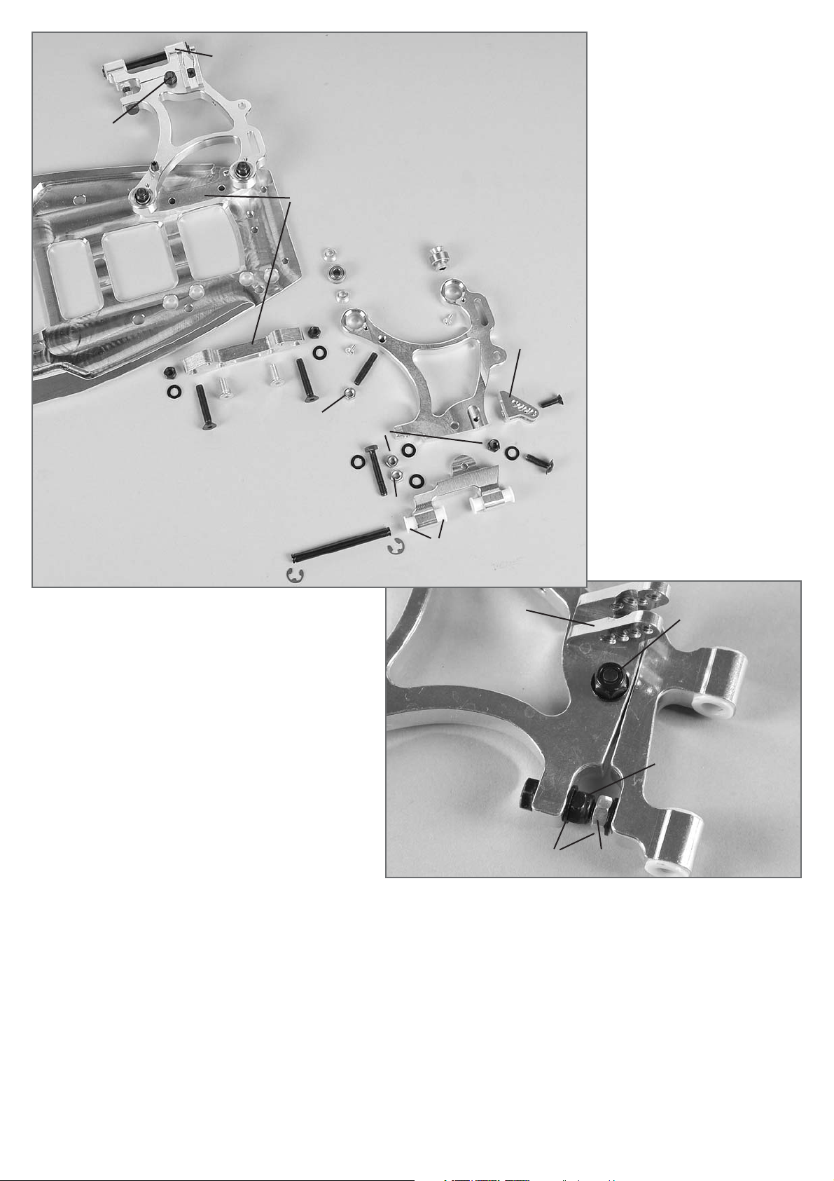
1. Alu-Karosseriehalter mit den M4x8
Senk-Schrauben am Chassis befestigen.
2. Die Kunststoffhalter für die AkkuHaltestrebe auf die rechte (in Fahrtrichtung) CFK Chassisversteifung
mittels M4x16 Senk-Schrauben
montieren. CFK Chassisversteifungen mit M4x14 Senk-Schrauben
und den Einpress-muttern
(Einpressmuttern von oben) auf das
Chassis schrauben.
3. Kunststoff-Karosseriehalter mit den
4,2x13 Senk-Schrauben an den
Alu-Karosseriehaltern befestigen.
4. Kohlefaser-Seitenschutzleisten auf
die Karosseriehalter stecken.
Tipp: Durch Weglassen der mittleren 2
Einpressmuttern je Seite kann die
Flexibilität des Chassis beeinflusst
werden (Chassis wird weicher).
Alle metrischen Schrauben sind mit Schraubensicherungslack zu sichern.
All metric screws need to be secured with thread lock fluid.
Baustufe 1
Teile sind in
Beutel A,A1
CFK- Chassisversteifung
Einpressmutter
Karosserieklammer
M4x8
Schraube/
Screw
M4x14
Schraube/Screw
Alu-Karosseriehalter
KunststoffKarosseriehalter
4,2x13
Schraube/Screw
Kohlefaser-Seitenschutzleisten
Kunststoffhalter
Plastic body mount
M4x16
Dämpfungsgummi
Dampening rubber
Karosserieklammer
Body clip
CFK-Akkuhaltestrebe
CFK-Akkuhaltestrebe
Fahrtrichtung
1. Fix the alloy body mount on the chassis using the M4x8
countersunk screws.
2. Mount the plastic mount for the battery holder brace on
the right (in direction of motion) CFK chassis stiffening by
means of M4x16 countersunk screws. Screw the CFK
chassis stiffenings with M4x14 countersunk screws and
insert nuts (insert nuts from the top) on the chassis.
3. Fix the plastic body mount with the 4.2x13 countersunk
screws on the alloy body mounts.
4. Put the carbon fiber side guard strips on the body mounts.
Tip: By omitting the 2 center insert nuts on each side you can
influence the flexibility of the chassis (chassis becomes more
smooth).
Direction of motion
CFK battery holder brace
Position 1
The parts are in
the bags A, A1
CFK chassis
stiffening
Insert nut
Einpressmutter
Insert nut
Alloy body
mount
Kunststoffhalter
Plastic mount
Body clip
Plastic body mount
Carbon fiber side
guard strips
CFK battery holder brace
W
orld Cham
pion 2007
European Cham
pion 2007
Germ
an Cham
pion 2007
1073/5
Querlenker hint. rechts/
Rear wishbone right
1072/5
Querlenker hint. links/
Rear wishbone left
1072/5
Querlenker hint. links/
Rear wishbone left
1073/1
Schwenkteil hinten
rechts/Rear lower
swivel part right
Hinterachse
Sicherungsscheibe/
Retaining washer Ø 5
Kegelscheibe/
Taper disk
M3x6
Stopp-Mutter/
Stop nut M5
Stopp-Mutter/
Stop nut M5
Stopp-Mutter/
Stop nut M5
Mutter/
Nut M5
Mutter/
Nut M5
Scheibe/
Disk Ø 5,3
Schraube/Screw
M5x30
Schraube/
Screw M5x16
Schraube/
Screw M5x16
Schraube/
Screw M5x16
Scheibe/
Disk Ø 5,3
Scheibe/
Disk Ø 5,3
Gleitbuchse
Bund-Gleitbuchse/
Collar guide bush
Kugelbüchse/
Ball-type
nipple
M4x14
Schraube/
Screw
Alu-Hinterachsunterlage
Querlenkerstift/
Wishbone pin 6x65mm
1072/1
Schwenkteil
hint. links/Rear
swivel part left
1072/1
Schwenkteil
hint. links/Rear
swivel part left
Stoßdämpferbefestigung
Stoßdämpferbefestigung
Damper mount
Baustufe 2
Teile sind
in Beutel B
M5x30
Gewindestift
Headless pin
M5x25
M5x30 Truck
M5x14
M5x20 Truck
Position 2
The parts are
in the bag B
Rear axle
Alloy support
for rear axle
Damper
mount
Guide bush
Mutter M5
StoppMutter M5
Scheibe/Disk
Ø 5,3
Schraube/
Screw
M5x30
Stop nut M5
Nut M5
1. Die Kugelbüchsen in die Querlenker
einpressen. Die eingepressten Kugelbüchsen mit den M3x6 LinsenFlachkopfschrauben sichern.
2. Bund-Gleitbuchsen nach Abb. in
die Schwenkteile eindrücken.
3. Schwenkteil mit M5x16 LinsenFlachkopfschraube (von unten),
Ø 5,3 Scheibe und M5 Mutter (von
oben) nach Abb. am Querlenker befestigen, M5 Mutter nur leicht anziehen. M5x30 Sechskantschraube,
Ø 5,3 Scheiben und M5 Muttern
nach Abb. montieren.
4. Alu-Stoßdämpferbefestigung mit
M4x14 Senk-Schraube am Querlenker befestigen.
5. M5x25 (M5x30 bei Truck)
Gewindestift und M5 Mutter nach
Abb. in den Querlenker schrauben.
6. Vormontierten Querlenker mit M5x30
Senk-Schrauben, Ø 5,3 Scheiben und
M5 Muttern auf die Hinterachsunterlage schrauben. Dabei je eine Kegelscheibe wie abgebildet ober- und
unterhalb der Kugelbüchse mitmontieren.
7. Komplette Einheit mit M5x14
(M5x20 bei Truck) Senk-Schrauben
auf dem Chassis befestigen.
Tipp: Hinterachsunterlagen links und
rechts sind unterschiedlich. Vor der
Montage bitte darauf achten, dass die
Bohrungen mit dem Chassis übereinstimmen. Kegelscheibe immer mit der
dünnen Seite zur Kugelbüchse montieren.
1. Mould the ball-type nipples in the wishbone. Secure the
moulded in ball-type nipples with M3x6 lenticular flange head
screw.
2. Push the flange guide bushes into the swivel part according
to the illustration.
3. Fix the swivel part with M5x16 lenticular flange head screw
(from the bottom), Ø 5.3 disk and M5 nut (from the top) on
the wishbone according to the illustration, tighten screw only
slightly. Mount M5x30 hexagon head screw, Ø 5.3 disks and
M5 nuts according to the illustration.
4. Fix the alloy shock absorber fastening with M4x14 countersunk screw on the wishbone.
5. Screw M5x25 (M5x30 for Truck) thread pin and M5 nut in the
wishbone according to the illustration.
6. Screw the premounted wishbone with M5x30 countersunk
screws, Ø 5.3 disks and M5 nuts on the support for rear axle.
In doing so, mount one taper disk each above and below the
ball-type nipples as illustrated.
7. Fix the complete unit with M5x14 (M5x20 for Truck) countersunk screws on the chassis.
Tip: The supports for rear axle on the left and on the right are different. Before assembling, please make sure that the borings
match the chassis. Always mount the taper disk with the thin
side towards the ball-type nipple.
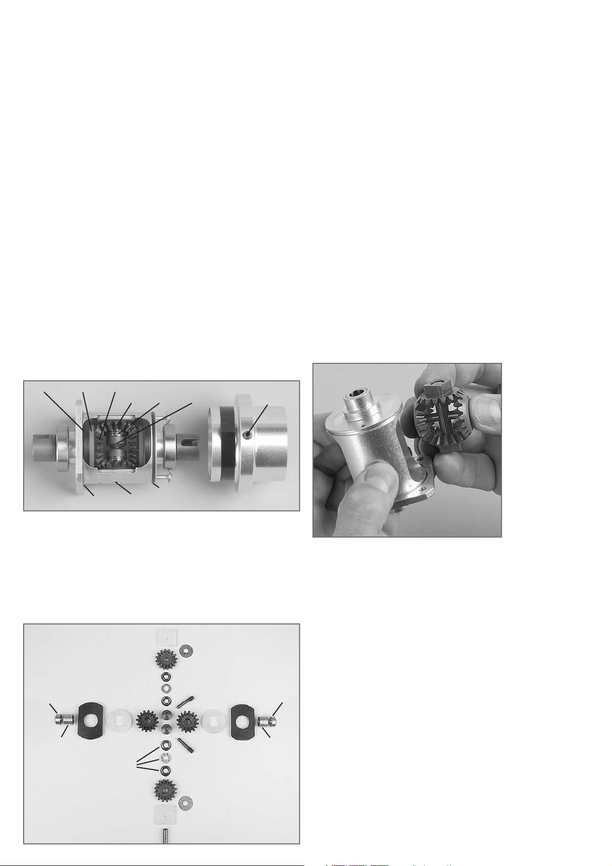
6067
8491
8496/1
Alu-Differentialgetriebe
4-fach selbstsperrend
Alloy differential gear
4-fold self-locking
Alu-Differentialgetriebe
4-fach selbstsperrend
8496/2
8487
6917/8
8486/2
8500/1
8500/3
8500/2
8493/5
O-Ring groß/big
O-Ring
klein/small
6068
6067
6067
8491
8491
8496/1
8500/3
8500/2
8500/2
8496/2
8501/2
8501/2
8500/1 8500/1 8600/58600/5
8499/1 8499/1
6743
6743
8496/3
6068
8490
Montage
Kugellager 8493/05 auf das Alu-Differentialgehäuse aufdrücken.
Nach Abb. die Diff.-Kegelzahnräder 8500/3 und 6067 mit den Reibscheiben
8500/2 und den Anlaufplatten (im Paket) in das Alu-Differentialgehäuse 8486
bzw. 8486/2 einführen. Jetzt beide Diff.-Antriebsachsen 6069/1 bzw. 6069/2
und die Kegelrad- achse 6068 bzw. 8490 eindrücken. Die Bohrungen des
Diff.-Gehäuses müssen mit den Bohrungen der Diff.-Kegelzahnräder fluchten.
Bei einem Versatz der Bohrungen muss das komplette Zahnradpaket aus
dem Diff.-Gehäuse entnommen und die Diff.-Kegelzahnräder um 1 Zahn zueinander versetzt werden. Danach das komplette Paket wieder in das Diff.Gehäuse einführen. Bei Verwendung des FG Montagewerkzeuges Best.-Nr.
8505 wird das Einsetzen der Diff.-Kegelzahnräder bzw. des kompletten Paketes wesentlich erleichert.
4-fach selbstsperrend: Kegelradachse etwas herausdrücken und eine Anlaufscheibe zwischen Kegelzahnrad B und Alu-Differentialgehäuse schieben.
Zweite Anlaufscheibe auf die gleiche Weise montieren.
Jetzt die Diff.-Kegelradachse 6068 bzw. 8490 etwa zur Hälfte herausdrücken.
Nachfolgend 1x Axiallager 8491, danach beide Druckscheiben 8496/1 mit
Konus gegeneinander zur Mitte und zuletzt das zweite Axiallager 8491 montieren. Diff.-Kegelradachse 8490 wieder vollständig in das Diff.-Gehäuse 8486
eindrücken. Diff.-Antriebsachsen 6069/1 bzw. 6069/2 drehen und prüfen, ob
das Diff.-Getriebe leichtgängig läuft. Zuviel Zahnradspiel kann mit beiliegenden Passscheiben 6743 (5x17x0,1) ausgeglichen werden.
Etwa eine halbe Tube FG Klüber Allzweckfett 6501 auf die Diff.-Kegelzahnräder geben und die O-Ringe 8489 in die vorgesehene Nut des Alu-Diff.-Gehäuse einlegen.
Schrumpfschlauch 8496/3 nach Abb. auf die Differentialhülse mittels Haarföhn aufschrumpfen.
Jetzt das Stahl-Zahnrad groß 48 Zähne mittels den Senkschrauben M4x8
montieren. Alu-Hülse 8487 nach Abb. auf das Diff.-Gehäuse aufschieben.
Danach die Einstellschrauben 8496/2 in die M5 Bohrungen der Alu-Hülse eindrehen, bis diese zwischen den Druckscheiben 8496/1 anliegen, etwas Schraubensicherungslack verwenden. Alu-Hülse mittels den M3 Schrauben fixieren.
Erläuterung
Die Sperrwirkung bei einem selbstsperrenden Differentialgetriebe entsteht
durch das entstehende Drehmoment, in dem die Kegelzahnräder 8500/3 bzw.
6067 auf die Reibscheibe bzw. Anlaufscheibe drücken und durch erhöhte
Reibung abgebremst werden. Zusätzlich können diese Differentialgetriebe
durch die Einstellschrauben in der Alu-Hülse noch mechanisch gesperrt werden, indem diese im Uhrzeigersinn eingeschraubt werden. Um das Differential mechanisch zu sperren, beide Einstellschrauben gleichmäßig im Uhrzeigersinn eindrehen. Durch gleichmäßiges Herausdrehen (gegen den Uhrzeigersinn) erhalten Sie weniger Sperrwirkung.
Ersatzteile/ Spare parts
6067 Diff.-Kegelzahnrad B, 2St./ Differential gearwheel B, 2pcs.
6068 Diff.-Kegelradachse, 1St./ Bevel differential gear axle, 1pce.
6717/8 Linsen-Flanschkopfschr. M3x8, 5St./ Lenticular flange head
screw M3x8, 5pcs.
6743 Passscheiben 5x17x0,1, 10St./ Shim rings 5x17x0,1, 10pcs.
8486 Alu-Differentialgehäuse, 1St./ Alloy differential housing, 1pce.
8486/2 Alu-Differentialgeh. 4-fach selbstsp., 1St./ Alloy diff.housing,four
fold, self-lock., 1pce.
8487 Alu-Hülse, 1St./ Alloy socket, 1pce.
8489 O-Ringe, 2St./ O-rings, 2pcs.
8490 Kegelradachse, 1St./ Bevel wheel axle ,1pce.
8491 Axialkugellager 5x12x4, 1St./ Thrust ball bearing 5x12x4, 1pce.
8493 Kugellager 15x28x7, 2St./ Ball bearing 15x28x7, 2pcs.
8496/1 Druckscheibe, 2St./ Pressure disk, 2pcs.
8496/2 Einstellschraube, 2St./ Adjusting screw, 2pcs.
8496/3 Schrumpfschlauch, 2St./ Heat shrink tube, 2pcs.
8499/1 Nadellager für Diff., 2St./ Needle bearing for differential, 2pcs.
8600/5 Bronzebuchse 8x12x5, 2St./ Bronze bushes 8x12x5, 2pcs.
8500/1 Anlaufplatte, 2St./ Stop plate, 2pcs.
8500/2 Reibscheibe, 2St./ Friction disk, 2pcs.
8500/3 Diff-Kegelzahnr. selbstsperr., 2St./ Diff. gearwh., self-lock., 2pcs.
8501/2 Anlaufscheibe, 2St./ Stop disk, 2pcs.
Bei Verwendung des
FG Montagewerkzeuges Best.-Nr. 8505
wird das Einsetzen
der Diff.-Kegelzahnräder bzw. des kompletten Paketes wesentlich erleichert.
Mounting
Press ball bearing 8493 on the alloy diff. housing.
Insert the diff. bevel gear wheels 8500/3 and 6067 together with the friction
disks 8500/2 and the stop plates (in the set) into the alloy differential housing
8486 or 8486/2 as shown on the picture. Now press in both differential driving axles 6069/1 or 6069/2 and also the bevel wheel axles 8490 or 6068. The
borings of the differential housing must be in true alignment with the borings
of the differential bevel gear wheels. If you notice a misalignment of the borings, take the complete package out of the differential housing and replace
the diff. bevel gear wheels one tooth offset. Then mount the complete package back in the diff. housing.
Quadruple self-locking: Squeeze out the bevel wheel axle a little and push
a stop disk between bevel gear wheel B and alloy diff. housing. Mount the second stop disk in the same way.
Now pull out the differential bevel wheel axle 6068/8490 half. Then mount
one thrust ball bearing 8491, afterwards both pressure disks 8496/1 with the
cones opposed to the middle and last the second thrust ball bearing 8491.
Press the differential bevel wheel axle 8490 completely into the differential
housing 8486 again. Turn the differential driving axles 6069/1 or 6069/2 and
check if the differential gear runs easy. Too much tooth clearance can be balanced with the enclosed shim rings 6743 (5x17x0,1).
Apply about half a tube of FG Klüber grease 6501 on the differential bevel gear
wheels and insert the o-rings 8489 in the provided groove of the alloy differential housing 8486.
Shrink the shrinkdown plastic tubing 8496/3 on to the differential socket with
a hair dryer.
Now mount the big steel gearwheel 48 teeth with the countersunk screws
M4x8. Push the alloy socket 8487 on to the differential housing as shown on
the picture. At the same time screw the adjusting screws 8496/2 into the M5
borings of the alloy socket until they lay firm between the pressure disks
8496/1, use some securing lacquer. Fix the alloy socket with the M3 screws.
Explanation
The valve effect of a self-locking differential gear is caused by the torque
which is developed when the bevel gear wheels 8500/3 or 6067 press on the
friction disk or stop plate and the higher friction causes a brake effect. Additional these differential gears can be locked mechanically through adjusting
screws in the alloy socket if you screw these in in clockwise direction. To lock
this differential mechanically, turn in both adjusting screw symmetrically in
clockwise direction. You achieve less valve effect if you unscrew them anticlockwise.
Inserting of the diff.
bevel gear wheels or
of the complete
package becomes
much easier if you
use the FG mounting
tool 8505.
Baustufe 5
Teile sind
in Beutel C
Hinterachse
Gewindestift/
Headless pin
M5x5
Schutzbalg
Kugelantriebswelle
Kugelantriebsachse
Gewindestift/
Headless pin
M4x4
Gewindestift/
Headless pin
M3x3
Sicherungsscheibe/Retaining washer Ø3,2
Mutter/Nut M4
Gleitbuchsen
Schraube/
Screw
M4x25
Schraube/Screw
M5x20
AluKugelgelenk
Einstellschraube/Adjusting screw 53mm
Muttern/Nuts R/L
Sicherungsscheibe/
Retaining washer Ø5
Sicherungsscheibe Ø5
Querlenkerstift 6x65mm
Querlenkerstift 6x65
Wishbone pin 6x65
Einstellclipse
Achsschenkelstift
Baustufe 4
Teile sind in
Beutel C
Hinterachse
Getriebeplatine
Abstützung MotorGetriebeplatine
M4x12
Schraube/
Screw
Alu-Dämpferplatine
Alu-Hinterachsbock
M4x16
Schraube/Screw
M4x8
Schraube/Screw
M4x16
Schraube/Screw M4x8
M4x20 Truck
Scheibe/Disk Ø4,3
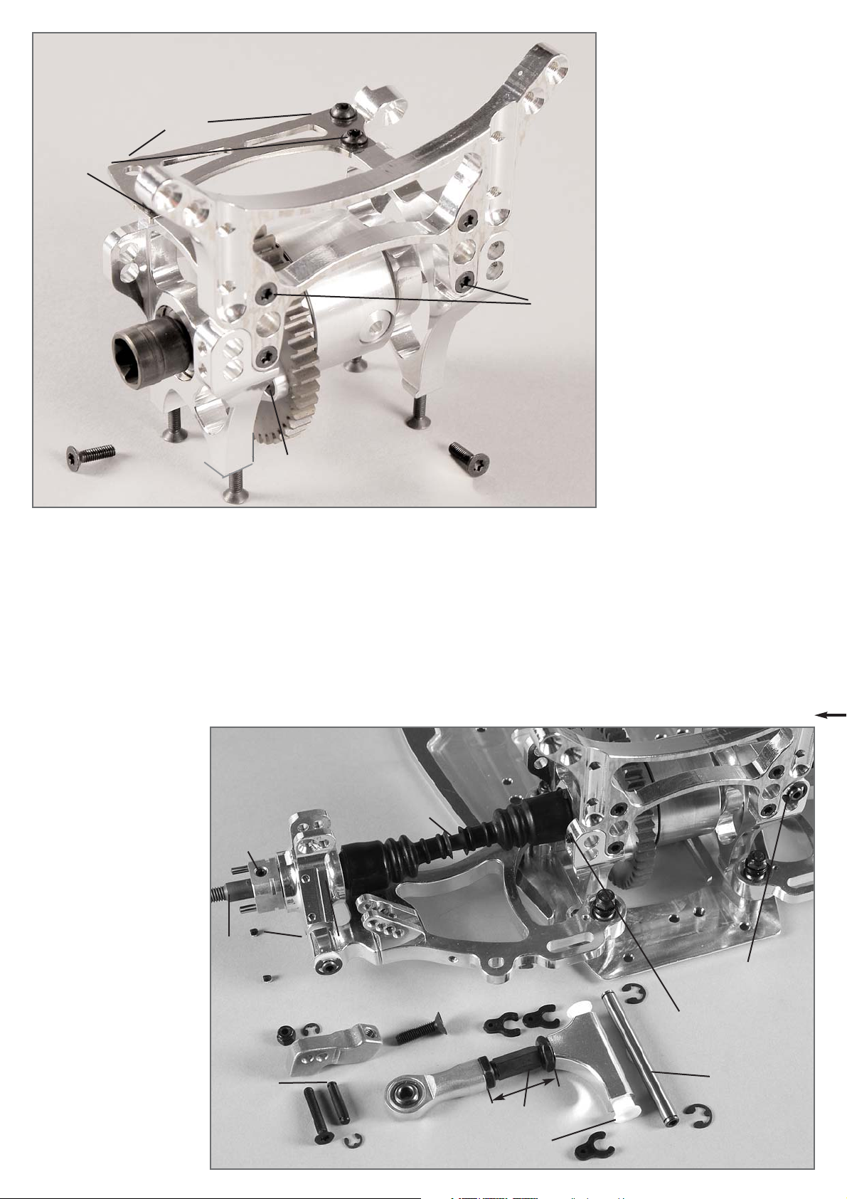
1. Stahl-Zahnrad 48 Zähne nach Abb.
auf das Diff.-Gehäuse aufschieben
und mit den Senk-Schrauben M4x8
festschrauben.
2. Alu-Hinterachsböcke nach Baustufe 4
auf die Kugellager des Differentialgetriebes aufdrücken und mit der
Alu-Dämpferplatine mit M4x12 Zylinder-Schrauben sowie die Getriebeplatine mit M4x8 Linsen-Schrauben
(bei Truck mit M4x20 und AluHinterachsunterlage) und Ø 4,3
Scheiben montieren.
3. Abstützung Motor-Getriebeplatine
mit einer M4x8 (M4x20 bei Truck)
Linsen-Schraube (und Alu-Distanz
bei Truck) und 4,3 Scheibe nach
Abb. montieren.
4. Komplette Einheit mit M4x16 SenkSchrauben zuerst auf die AluHinterachsunterlagen, dann auf
dem Chassis montieren.
Schraube/Screw
M4x8
Scheibe/Disk
Ø4,3
1. Gleitbuchsen in den Alu-Querlenker hinten oben einpressen.
2. Sechskantmutter M8 Linksgewinde auf die Einstellschraube 39mm drehen. Diese in den AluQuerlenker eindrehen, danach Sechskantmutter M8 Rechtsgewinde und das Alu-Kugelgelenk auf
das Rechtsgewinde der Einstellschraube so aufdrehen, dass der Sechskant der Einstellschraube mittig sitzt
3. Alu-Querlenker nach Abb. mit dem Querlenkerstift Ø6x65mm montieren und mit Ø5
Sicherungsscheiben befestigen.
4. Die Querlenkerstifte mit Gewindestift M4x4 klemmen.
5. Kugel-Antriebsachse in die mit Kugellagern bestückten Achsschenkel drücken und FelgenVierkantmitnehmer mit dem Absatz zum Lager zeigend mit M5x5 Gewindestiften befestigen.
6. Kugel-Antriebsset nach beiliegender Anleitung montieren.
7. Alu-Achsschenkel und Querlenkerstift 6x65 nach Abb.
einbauen und mit M3x3 Gewindestiften und Ø 5 Sicherungsscheiben befestigen.
8. Die Distanzscheiben aus
Gummi in die runde Aussparung der Kugelantriebsachse
und Kugel-Diff.-Achse eindrücken. Schutzbalg nach
Abb. montieren.
9. Kugeln einfetten und in die
Kugelantriebswelle eindrücken.
Kugelantrieb nach beiliegender Anleitung montieren.
Alu-Dist. Truck
Stahl-Zahnrad 48 Z.
Steel gear 48 teeth
1. Push steel gearwheel 48 teeth on
the diff. housing and screw it tight
with the countersunk screws M4x8.
2. Press on the alloy rear axle mounts
on the ball bearings of the differential gear according to the position 4
and mount them with the alloy damper plate with M4x12 socket cap
screws as well as the gear plate
with M4x8 pan-head screws (M4x20
and alloy rear axle base for Trucks)
and Ø 4.3 disks.
3. Mount the support engine gear
plate with a M4x8 (M4x20 for Truck)
pan-head screw (and alloy distance
for Truck) and 4.3 disk according to
the illustration.
4. First mount the complete unit with
M4x16 countersunk screws on the
alloy supports for rear axle, then on
the chassis.
Position 4
The parts are
in bag C
Gear plate
Support enginegear plate
Alloy
damper
plate
Rear axle
Alloy rear
axle mount
Position 5
The parts are
in bag C
Rear axle
Ball driving
axle
Protecting
expansion bend
Ball driving
shaft
Upright pin
Guide bushes
Wishbone
pin 6x65mm
Adjusting clips
Alloy balland-socket
joint
1. Press the guide bush in the alloy wishbone at the
rear top.
2. Screw the hexagon socket nut M8 with left-handed thread on the adjusting screw 39mm. Turn it
in the alloy wishbone, then unscrew the hexagon
nut M8 with right-handed thread and the alloy
ball-and-socket joint on the right-handed screw
of the adjusting screw in a way that the hexagon
of the adjusting screw is centered.
3. Mount the alloy wishbone with the wishbone pin
Ø6x65mm according to the illustration and fix it
with Ø5 retaining washers.
4. Clamp the wishbone pins with the headless pin
M4x4.
5. Press the ball driving axle into the uprights
equipped with ball bearings and fix the square
wheel driver with its offset towards the bearing
using M5x5 headless pins.
6. Mount the ball driving set according to the
enclosed instruction.
7. Fix the alloy upright and the wishbone pin
according to the illustration and fix them using
M3x3 headless pins and Ø 5 retaining washers.
8. Push the distance disks made off rubber in the
round slot of the ball driving axle and the ball
diff. axle. Mount the protecting expansion bend
according to the illustration.
9. Grease the balls and inpress them into the ball
driving shaft. Mount the ball driving according to
the enclosed instruction.
Stifte in das Sackloch eindrücken.
Impress the pins
into the pocket
hole.
Schraube/
Screw
M5x20
Schraube/Screw
M4x25
29mm
Querlenker mittels Einstellclipse
ausdistanzieren./ Align the
wishbone with adjusting clips.
Achsschenkelverlängerung/
Upright lengthening
Hinterachse
Sicherungsscheibe Ø 3,2
Achsschenkelstift
Stopp-Mutter/
Stop nut M4
Baustufe 6
Teile sind
in Beutel C
Position 6
The parts are
in bag C
Upright pin
Rear axle
Retaining
washer Ø 3.2
1. Alu-Achsschenkelverlängerung nach Abb. montieren und mit
Achsschenkelstift, Ø 3,2 Sicherungsscheibe, Senk-Schraube
M4x25 und M4 Stopp-Mutter befestigen.
2. Kugelgelenk mit Alu-Gelenkkugel mit Senk-Schraube M5x20 auf
die Achsschenkelverlängerung schrauben.
Tipp: Entsprechend der Einstellung der Vorspur muss der obere
Querlenker mittels den Einstellclipsen ausdistanziert werden.
1. Mount the alloy upright lengthening according to the illustration and
fix it with the upright pin, Ø 3.2 retaining washer, countersunk screw
M4x25 and M4 stop nut.
2. Screw the ball-and-socket joint with alloy joint ball using the countersunk screw M5x20 on the upright lengthening.
Tip: The upper wishbone needs to be aligned according to the setting
of the toe-in by means of adjusting clips.
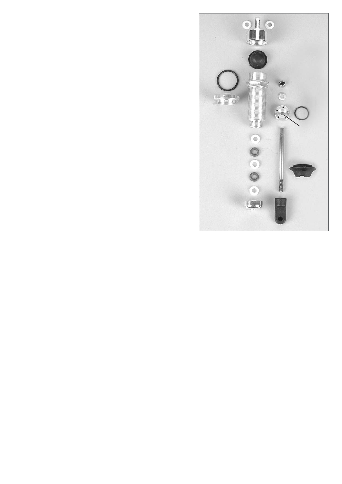
1. Je 2 Führungen mit Bund in den Dämpferverschluss 04 oben einpressen,
Volumenausgleich in den Dämpferverschluss einlegen. O-Ringe in die
Verstellringe einlegen und auf das Stoßdämpfergehäuse schrauben (flache Seite
in Richtung Sechskant).
2. Je 1 Führung mit Bund in den Dämpferverschluss 04 unten mit dem Bund zum
Innengewinde zeigend einpressen.
3. Je 1 Führung mit Bund ins Stoßdämpfergehäuse mit dem Bund zum kleinen
Gewinde zeigend einpressen.
4. Dämpferkolben mit der kleineren Vertiefung zur Kolbenstange zeigend montieren
und mit Scheibe 3,2mm und Stopp-Mutter M3 festziehen.
5. Kolbenstange nun in das Stoßdämpfergehäuse stecken in folgender
Reihenfolge: O-Ring/ Führung o. Bund/ O-Ring, die leicht eingeölt sein sollten,
dann auf die Kolbenstange schieben.
6. Stoßdämpferverschluss 04 unten auf die Kolbenstange schieben und mit dem
Stoßdämpfergehäuse verschrauben. Dämpferbefestigung kurz auf das Gewinde
der Kolbenstange schrauben, bis kein Gewinde mehr zu sehen ist. Die
Kolbenstange darf hierbei nicht beschädigt werden. Wir empfehlen deshalb die
Haltezange Best.-Nr. 6854 zu verwenden.
7. Stoßdämpfer bis zur Markierung mit Öl befüllen.
8. Kolbenstange mehrmals langsam ins Stoßdämpfergehäuse schieben und herausziehen, damit die Luftblasen im Öl nach oben steigen. Wenn keine
Luftblasen mehr aufsteigen, Dämpferverschluss oben ca. 2 Umdrehungen aufschrauben. Kolbenstange langsam ins Stoßdämpfergehäuse schieben, bis ca.
5mm von der Kolbenstange noch zu sehen sind, nun den Dämpferverschluss
oben festschrauben.
9. Das überschüssige Öl tritt an der Querbohrung des Dämpferverschlusses aus.
10.Nun die blauen Federn auf die hinteren Stoßdämpfer montieren und mit dem
Federteller sichern. Bei den vorderen Stoßdämpfern ist mit den roten Federn
gleich zu verfahren.
Dämpferverschluss oben
Dämpferverschluss
unten/Lower shock
absorber seal
Dämpferbefestigung kurz
Stoßdämpfergehäuse
Federteller
Führung
mit Bund
Führung mit
Bund/Guiding
with waistband
Volumenausgleich
Verstellring
O-Ring
O-Ring
Mutter/Nut M3
Scheibe/Disk
Ø3,2
O-Ring
O-Ring
Führung o.
Bund/Guiding
w/o waistband
Kolben/
Piston
Kolbenstange kurz
Baustufe 7
Teile sind
in Beutel D
1. Mould 2 guides each with collar into the shock plug 04 at the top, insert the volume compensation into the shock absorber seal. Insert O-rings
into the adjustable rings and screw them on the shock absorber housing (flat side in direction of the hexagon).
2. Mould 1 guide with collar each in the shock absorber seal 04 at the bottom with the collar towards the internal thread.
3. Mould 1 guide with collar each into the shock absorber housing with the collar showing towards the smaller thread. Mount the securing rings
3.2mm in the first chamfer of the short piston rod.
4. Mount the shock piston with the recess towards the securing ring and fix it with disk Ø 3.2mm and stop nut M3.
5. Now put the piston shaft in the shock absorber housing in the following order: O-ring/ guiding w/o collar/ O-ring, which should be slightly
oiled, then push it on the piston shaft.
6. Push the shock absorber locking 04 bottom on the piston shaft and screw it with the shock absorber housing. Screw the shock fastening short
on the thread of the piston shaft until you cannot see anymore of the thread. Make sure the piston rod is not damaged, we therefore recommend to use the pliers Item N°. 6854.
7. Fill the shock absorber with oil up to the marking.
8. Push the piston shaft several times slowly into the shock absorber housing and pull it out again, in a way that the air bubbles in the oil can rise.
If no more air bubbles are rising unscrew the shock absorber seal top by about 2 turns. Shift the piston shaft slowly into the shock absorber
housing until you can only see about 5mm of the piston shaft, now firmly bolt the shock absorber seal.
9. The excessive oil will escape at the cross hole of the shock absorber seal.
10.Now mount the blue springs on the rear shock absorbers and secure them with the spring plate. Proceed in the same way with the front shock
absorbers using the red springs.
Position 7
The parts are
in bag D
Guiding
with
waistband
Upper shock
absorber seal
Volume compensation
Shock absorb.
housing
Spring plate
Piston shaft short
Shock fastening
short
Schrauben/Screws
4,2x22
Schraube/Screw
4,2x9,5
Schraube/Screw
2,9x9,5
Schraube/Screw
4,2x13
Dämpferplatine/
Shock absorber plate
Schraube/Screw M4x14
Schraube/
Screw M4x14
Karosseriestütze/
Ext. rear body mount
Karosserieauflage/
Body mount
Baustufe 8
Teile sind
in Beutel E
1. Karosseriestütze mit M4x14 Zylinder-Schrauben an Dämpferplatine
montieren. Für die Kunststoffteile sind die Blechschrauben 4,2x22/
4,2x9,5/ 2,9x9,5 sowie 4,2x13 zu verwenden. Kunststoffteile der
Heckstütze mit Ø 2mm Bohrer vorbohren, um die Montage der
2,9x9,5 Blechschrauben zu erleichtern.
2. Karosserieauflage zu einem späteren Zeitpunkt je nach Karosserietyp
in der Höhe einstellen.
3. Vormontierte hintere Stoßdämpfer mit M4x25 Senk-Schrauben und
M4 Stopp-Muttern, unten M4x14 Linsen-Schrauben befestigen.
1. Mount the body support on the shock absorber plate using M4x14
socket cap screws. Use the sheet metal screws 4.2x22/ 4.2x9.5/
2.9x9.5 as well as 4.2x13 for the plastic parts. Predrill plastic parts of
the rear support with Ø 2mm drill in order to facilitate the assembly of
the 2.9x9.5 sheet metal screws.
2. Adjust the height of the body mount front depending on the body
type later.
3. Fix the premounted rear shock absorbers using the M4x25 countersunk screws and M4 stop nuts, at the bottomM4x14 pan-head
screws.
Position 8
The parts are
in bag E
Baustufe 9
Teile sind
in Beutel J
Entlüftungsnippel
Stabi.-Draht
mit Kugelpfanne
Stabi.-Draht
mit Kugelführung
Klemmbolzen
M5 bzw. M6
Scheibe
5,3 o. 6,4
Stopp-Mutter
M5 oder M6
Gewindestift M5x5
Baustufe/
Position 9a
Klemmbolzen M6
Klemmbolzen M5
Kugelführung
Kugelpfanne
1. Entlüftungsnippel ins Chassis schrauben.
2. Je eine M5 bzw. M6 Mutter auf die Klemmbolzen
aufschrauben. Danach eine Scheibe 5,3 bzw.6,3
ansetzen und die Klemmbolzen nach Abb. in den
Querlenker montieren.
3. Von unten eine Scheibe 5,3/ 6,4 ansetzen und die
M5 bzw. M6 Stopp-Mutter auf den Klemmbolzenschrauben – Muttern noch nicht festziehen.
4. Den Stabi.-Draht mit Kugelführung in die Klemmbolzen drücken und mit den M5x5 Gewindestiften
klemmen. Die Kugelführung muss sich genau in
der Mitte des Chassis befinden. Die Muttern nun
festschrauben.
5. Mit dem Stabi.-Draht der Kugelpfanne genauso
verfahren. Die Kugelführung nicht zu tief in die
Kugelpfanne montieren, so dass beim Ausfedern
bzw. Einfedern die Kugelführung nicht auf den
Rand der Kugelpfanne drückt.
1. Screw the vent nipple in the chassis.
2. Screw each one M5 or M6 nut on the clamp bolt. Then affix a disk 5.3 or.6.3 and mount the
clamp bolts on the wishbone according to the illustration.
3. Affix a disk 5.3/ 6.4 from the bottom and screw the M5 or M6 stop nut on the clamp bolt –
do not fasten the nuts yet.
4. Press the fixing wire with ball bearing in the clamp bolt and clamp it using the M5x5 headless
pins. The ball guide needs to be positioned exactly in the center of the chassis.
5. Now firmly tighten the nuts. Proceed in the same way with the fixing wire of the ball guide.
There must be enough clearance between the ball guide and the ball socket in a way that the
vehicle does not block when deflecting and rebounding.
Position9
The parts are
in the bag J
Ball bearing traveler
Ball work pan
Fixing wire
with ball work pan
Vent nipple
Clamp bolt
M6
Clamp bolt
M5
Fixing wire with
ball bearing
traveler
Headless
pin M5x5
Clamp bolt
M5 or M6
Disk
5,3 o. 6,4
Stop nut M5
or M6
Schraube/Screw M4x25
Mutter/ Nut M4

Schraube/Screw
2,9x22
Schraube/Screw
2,9x16
Karosseriebolzen/
Body bolt
Karosseriebolzen/
Body bolt
Karosserieklammer/
Body clip
Alu-Dämpferplatine
Alloy damper plate
Alu-Dämpferplatine
Alloy damper plate
Karosserieklammer/
Body clip
Abbildungen 10/ 10a/ 10b nur bei Renn-Trucks!
Entsprechend der verwendeten Renn-Truck Karosserie
Karosseriehalter an die Dämpferplatine montieren.
Karosseriehalter für Renn-Truck
Karosserie Best.-Nr. 3070 MAN-Truck
Body mount for Race Truck body
Item N°. 3070 MAN-Truck
Karosseriehalter für Renn-Truck
Karosserie Best.-Nr. 3049 CAT-Truck
Body mount for Truck Body
Item N°. 3049 CAT-Truck
Baustufe 10a
Teile sind
in Beutel E
Baustufe 10
Teile sind
in Beutel E
Position 10
The parts are
in bag E
Position 10a
The parts are
in bag E
Illustrations 10/ 10a/ 10b only for Race Trucks!
Mount the body mount on the shock mount according to the used
Race Truck body.

Karosserieauflage/
Rear body mount
Schraube/ Screw M4x14
Schrauben/Screws
4,2x22
Schraube/
Screw
4,2x9,5
Alu-Dämpferplatine
Alloy damper plate
Karosseriehalter für Renn-Truck Karosserie
Best.-Nr. 3053 MB-Truck 1834 und Best.-Nr. 3064 Atego-Truck
Body mount for Race Truck body
Item N°. 3053 MB-Truck 1834 and Item N°. 3064 Atego-Truck
Karosserieauflage zu einem späteren Zeitpunkt einstellen.
Adjust body mount later.
Baustufe 10b
Teile sind
in Beutel E
Position 10b
The parts are
in bag E

1. Krümmer und Dichtung an den Motor mit den
M5x16 Linsen-Schrauben nach Abb. montieren.
2. Die 4 Gewindestifte M5x20 mit
Schraubensicherungslack versehen und in das
Motorgehäuse eindrehen, bis diese noch ca.
9mm aus dem Gehäuse ragen.
3. Motorflansch mit der Ausfräsung zum Zylinder
zeigend auf das Gehäuse bzw. Gewindestifte
drücken und mit den M5 Stopp-Muttern befestigen.
4. FG 4-Backen-Kupplung lt. beiliegender
Montageanleitung montieren.
5. FG Ansaug-Geräuschfilter lt. beiliegender
Montageanleitung montieren.
Gewindestift M4x6 mit Schraubensicherung bis zum Kontakt zur Federführung eindrehen. Durch
gleichmäßiges Eindrehen wird die Federkraft erhöht und die Kupplung greift später ein.
Screw the headless pin M4x6 with screw locks until it contacts the spring guide. By uniform screwing
the spring force will be increased and the clutch will cam in later on.
Baustufe 11
Teile sind
in Beutel G
Gewindestift
M5x20
StoppMutter M5
Krümmer
Ausfräsung
Motorflansch/
Engine flange
Kupplungsmitnehmer/
Clutch carrier
Kupplungsbacken
Kupplungsfeder
Kupplungsfeder
Deckscheibe
Schraube/
Screw
M6x35
Schraube/
Screw M5x16
Gewindestift/
Headless pin
M4x6
Schrauben
M3x5
Federführung
Federführung
FG Ansaug-Geräuschfilter
Baustufe 11a
Teile sind
in Beutel G
1. Mount the manifold and the gasket on the engine
using M5x16 pan-head screws according to the
illustration.
2. Provide the 4 headless pins M5x20 with threadlock fluid and screw them into the engine housing until they will only protrude the housing by
about 9mm.
3. Press the engine flange with the milling groove
directed towards the cylinder on the housing or
on the headless pins and fix them using the M5
stop nuts.
4. Mount the FG 4-block clutch according to the
enclosed assembly instruction.
5. Mount the FG inlet silencer according to the
enclosed assembly instruction.
FG inlet silencer
Manifold
Headless pin
M5x20
Stop nut M5
Clutch blocks
Spring guide
Clutch spring
Screws
M3x5
Cover disk
Position 11
The parts are
in bag G
Position 11a
The parts are
in bag G
Clutch spring
Spring guide

Schraube/Screw
M5x14
Schraube/
Screw
M5x14
Schraube/
Screw M5x12
GetriebeflanschMotorbock
Alu-Getriebeplatte/
Alloy gear plate
Alu-Getriebeplatte/
Alloy gear plate
Schraube/
Screw
M4x12
Schraube/Screw
M6x10
Schraube/
Screw
M6x10
Schraube/
Screw
M6x10
Schraube/
Screw
M6x10
Schraube/
Screw
M6x10
Schraube/
Screw
M6x10
Alu-Zahnradmitnehmer/
Alloy gear carrier
MotorbefestigungsScheibe/ Engine
fastening disk
Scheibe/Disk
10x16x1
Scheiben/
Disks
10x16x1
Scheiben/
Disks
10x16x1
Scheiben/Disks
10x16x1
Kupplungsglocke/
Clutch bell
Stahl-Zahnrad16 Zähne/
Steel gearwheel 16 teeth
Stahl-Zahnrad16 Zähne/
Steel gearwheel 16 teeth
Stahl-Zahnrad/
Steel gearwheel
Stahl-Zahnrad/
Steel gearwheel
Kunststoff-Zahnrad/
Plastic gearwheel
Kunststoff-Zahnrad/
Plastic gearwheel
Getriebeachse
Distanzbuchse/
Distance bush 13x43
Gewindestift/
Headless pin M5x6
Gewindestift/
Headless pin
M5x6
Gewindestift M5x5
Baustufe12
Teile sind
in Beutel F
1. Distanzbuchse 13x43 in Getriebeflansch-Motorbock eindrücken, Alu-Getriebeplatte auf den AluGetriebeflansch-Motorbock mittels den M4x12
Zylinder-Schrauben befestigen.
2. Kupplungsglocke nach Abb. montieren. Die 5
Scheiben 10x16x1 nach Abb. zwischen
Kugellager und 23Z. (20Z. Truck) Stahl-Zahnrad
einlegen und Zahnrad nach Abb. mit den M5x6
Gewindestiften auf den Flächen der
Kupplungsglocke befestigen.
3. Getriebeachse mit der längeren Flachstelle zum
Kunststoffzahnrad zeigend einbauen. Alu-Zahnradmitnehmer, 41Zähne (44Zähne bei Renn-Truck)
Kunststoff-Zahnrad und Alu-Scheibe nach Abb.
auf die Getriebeachse stecken und mit M5x6
Gewindestiften auf den Flächen der Getriebeachse befestigen, dass die Getriebeachse und
der Alu-Zahnradmitnehmer bündig sind.
Linsenschraube M6x10 zur Sicherung in die Getriebeachse schrauben.
4. Komplette Getriebeachse durch die Kugellager
der Getriebeplatine und den GetriebeflanschMotorbock schieben und auf das andere Ende
der Getriebeachse nach Abb. Scheiben 10x16x1
und das 16 Zähne Stahl-Zahnrad montieren. Mit
M5x5 Gewindestiften auf den Flächen der Getriebeachse befestigen. Ebenfalls wieder Linsenschraube M6x10 zur Sicherung in die Getriebeachse schrauben.
5. Komplette Getriebeeinheit auf den Motorflansch
montieren, Schraube M 5x14 vom Getriebeflansch noch nicht festziehen.
1. Press the distance bush 13x43 into the gear box flange engine
mount, fix the alloy gear plate onto the alloy gear box flange engine
mount by means of the M4x12 cylinder screws.
2. Mount the clutch bell according to the illustration. Insert 5 disks
10x16x1 between the ball bearing and 23-teeth (20-teeth truck) steel
gearwheel and fix the gearwheel using the M5x6 headless pins on the
faces of the clutch bell according to the illustration.
3. Build in the gear axle with the longer wheel flat directed towards the
plastic gearwheel. Put the alloy gear carrier, 41 teeth (44 teeth for race
trucks) plastic gearwheel and alloy disk on the gear axle according to
the illustration and fix it on the surface of the gear axle using M5x6
headless pins, in a way that the gear axle and the alloy gear carrier are
aligned. Screw the pan-head screw M6x10 to secure the gear axle.
4. Shift the complete gear axle to the ball bearing of the gear plate and
mount the disks 10x16x1 and the 16-teeth steel gearwheel on the other side of the gear axle according to the illustration. Fix it on the other
surfaces of the gear axle using the M5x5 headless pins. Also screw the
pan-head screws M6x10 to secure the gear axle.
5. Mount the complete gear unit on the engine flange, don’t tighten
screw M5 x14 yet.
Position 12
The parts are
in bag F
Baustufe13
Teile sind
in Beutel F
Position 13
The parts are
in bag F
Pinion shaft
Headless
pin M5x5
Gear flange
engine mount
GetriebeflanschMotorbock
Gear flange
engine mount
Zentrierscheibe/
centric disk
längere Flachstelle/
longer flat spot

Tank
Motorbefestigungsscheibe/
Engine fastening disk
Schraube M4x6
zur Tankmontage
Abstützung MotorGetriebeplatte
Schraube/Screw
M5x14
Schraube M5x14
Schraube M5x20
für Truck mit
Distanzbuchse
Scheibe Ø5,3
Schraube M4x8
Schraube M4x20
für Truck mit
Distanzbuchse
Scheibe Ø4,3
Schraube/
Screw
M5x12
Schraube/Screw
M5x14
Baustufe14
Teile sind
in Beutel G
Baustufe14a
Teile sind
in Beutel C
1. Motor mit Getriebeeinheit, Krümmer und Luftfilter nach Abb. in das
Chassis montieren, mit den M5x12 Schrauben und den Motorbefestigungsscheiben am Chassis befestigen. Vor dem Festziehen der
Schrauben sollte das Zahnflankenspiel zwischen Stahl-Zahnrad groß
48Z. und Stahl-Zahnrad 16Z. eingestellt werden.
2. M5x14 Schraube am Alu-Getriebeflansch festziehen.
3. Den Kraftstofftank mit den M4x6 Senk-Schrauben auf dem Chassis
befestigen. Diese Schrauben nur mit mittelfestem Schraubensicherungslack sichern, um eine Beschädigung beim späteren Lösen der
Schrauben zu vermeiden.
4. Kraftstoffschläuche nach Abb. am Vergaser montieren.
5. Motor mit M5x14 Schraube (M5x20 bei Truck und Distanz) an der
Abstützung Motor-Getriebeplatine befestigen.
Tipp: Bei der Montage des Motors einen 10mm breiten Papierstreifen zwischen die Zahnräder legen, Zahnräder gegeneinanderdrücken und ein
wenig drehen. Dann die Motorschrauben M5x12 festziehen. Papier entfernen und Getriebe durchdrehen, das Getriebe muss sich leicht drehen lassen.
1. Mount the engine with the gear unit, manifold and air filter in the
chassis according to the illustration, fix it with M5x12 screws and
the engine fixing disks on the chassis. Before fastening the
screws, you should adjust the clearance of the toothed flanges
between the steel gearwheel large 48 teeth and the steel gearwheel 16 teeth.
2. Fasten the M5x14 screw on the alloy gear flange.
3. Fix the fuel tank on the chassis using the M4x6 countersunk
screws. Secure these screws only with medium thread lock fluid in
order to avoid damages when loosening the screws later on.
4. Mount the fuel hose on the carburator according to the illustration.
5. Fix the engine to the support engine gear plate using M5x14
screws (M5x20 for Truck and distance).
Tip: When assembling the engine, put a paper strip with a width of
10mm between the gearwheels, press the gearwheels against one
another and turn them a little. The fasten the engine screws M5x12.
Remove the paper and spin the gear, the gear has to move smoothly.
Position 14
The parts are
in bag G
Screw M5x14
Screw M5x20
for Truck with
distance bush
Disk Ø5.3
Screw M4x6
for tank mounting
Position 14a
The parts are
in bag C
Screw M4x8
Screw M4x20
for Truck with
distance bush
Disk Ø4.3
Support engine
gear plate

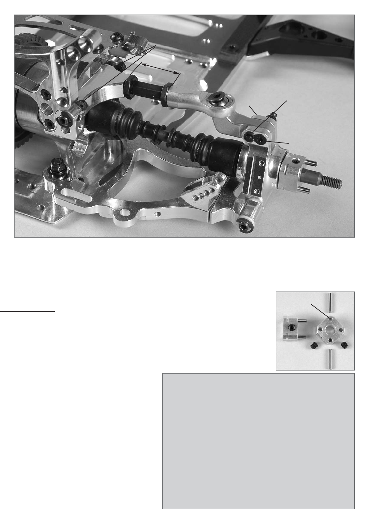
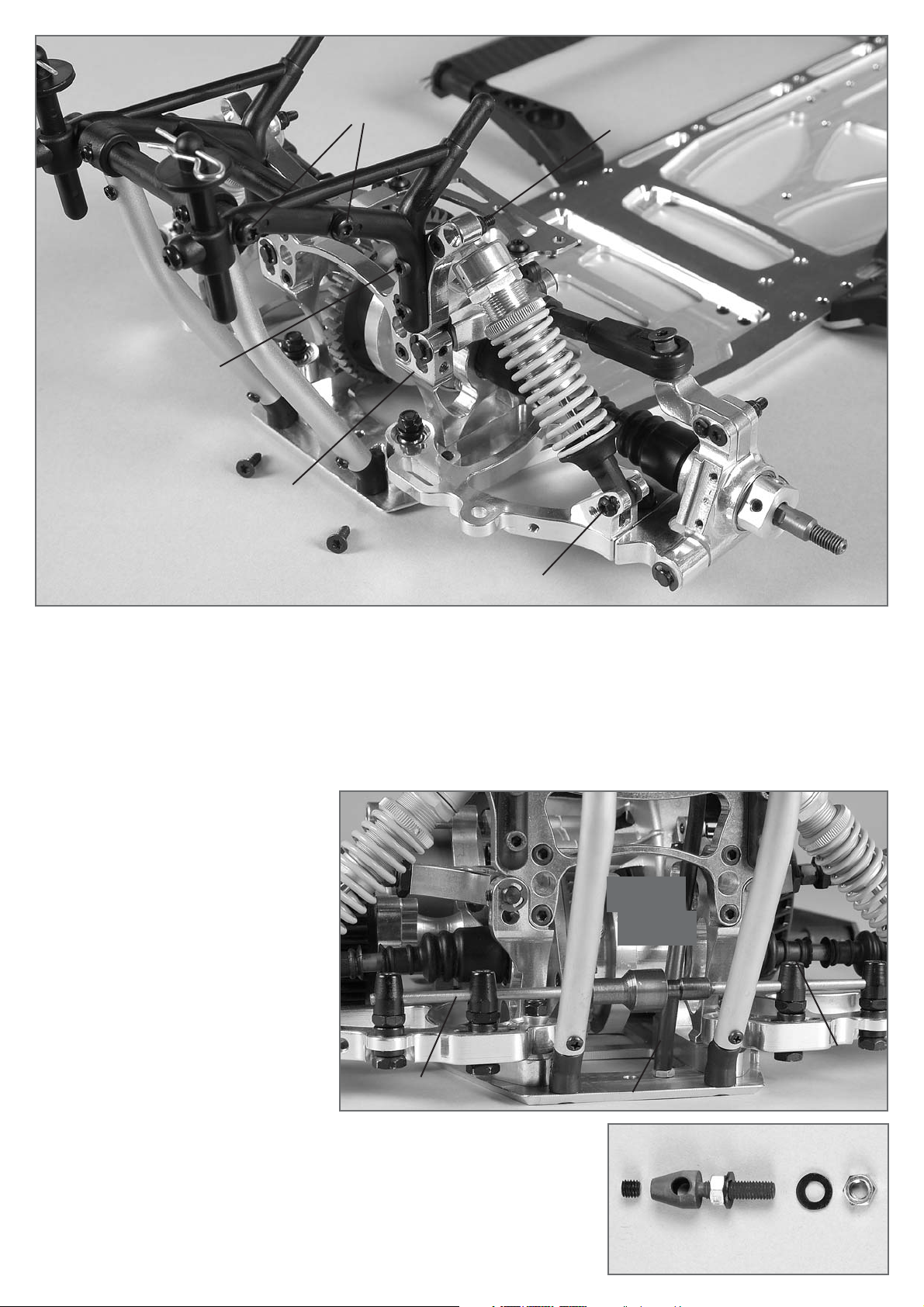
Bei der Montage der Vorderachse auch Baustufe 16 zur Hilfe nehmen.
1. Gleitbuchsen mit Bund zur Innenseite zeigend in die Bohrungen der
Alu-Vorderachsböcke 06 einpressen. Die länglichen Gleitbuchsen in
die Langlöcher oben der Vorderachsböcke einsetzen. Die Bohrung
in den länglichen Gleitbuchsen kann in 3 unterschiedlichen
Positionen eingesetzt werden. Darauf achten, dass alle in der gleichen Position montiert werden.
2. Die eingepressten Kugelbüchsen in den Alu-Querlenkern unten mit
M3x6 Linsen-Flanschkopfschrauben sichern. Die M5x25 (M5x30 bei
Truck) Gewindestifte und M5 Muttern nach Abb. montieren.
3. Die Sechskantmuttern mit Linksgewinde auf die Einstellschrauben
40mm aufdrehen, dann die Einstellschraube mit aufgedrehtem AluKugelgelenk in den oberen Alu-Querlenker eindrehen.
4. Vorderachse mit Bund in den deachsierten Alu-Achsschenkel mit
den vormontierten Kugellagern drücken und von der Innenseite
Gewindestift M5x20, Scheibe 5,3mm und mit einer M5 StoppMutter sichern. den Felgen-Vierkantmitnehmer 14mm (9mm bei
Truck) mit der Ausdrehung zum Kugellager zeigend montieren. Mit
den M4x4 Gewindestiften befestigen, nur leicht anziehen.
5. Alu-Lenkhebel mit M3x10 Schrauben am Alu-Achsschenkel vorne
nach Abb. befestigen.
6. Die vormontierten Alu-Querlenker nach Abb. an die AluVorderachsböcke montieren und mit Einstellclipsen und ggf.
Passscheiben ausdistanzieren. Die Querlenkerstifte mit
Sicherungsringen 5mm sichern. Die Querlenkerstifte mit M5x5
Gewindestifte klemmen. Die vormontierten Achsschenkel nach Abb.
mit M5x25 Senkschraube befestigen. Hierbei die Kegelscheiben und
5,3mm U-Scheiben zum oberen und unteren Querlenker montieren(
siehe Baustufe 16). Darauf achten, dass der kleinere Durchmesser der
Kegelscheibe zum Kugelgelenk zeigt.
Tipp: Auf richtigen Einbau der deachsierten Alu-Achsschenkel achten.
Die Gewinde-Aufnahme des Kugelgelenkes muss oben weiter innen
sein als unten.
For the installation of the front axle also pay attention to position 16.
1. Mould in the guide bushes with collar showing towards the inside
into the boring of the alloy front axle mounts 06. Insert the oblong
guide bushes into the oblong holes at the top of the front axle mounts.
It is possible to insert the boring into the oblong guide bushes in 3
different ways. Please make sure that all of them are mounted in the
same way.
2. Secure the pressed in ball-type nipples in the alloy
wishbones at the bottom with M3x6 lenticular flange head screws.
Mount the M5x25 (M5x30 for truck) headless pins and M5 nuts
according to the illustration.
3. Screw the hexagon socket nuts with left-handed threads on the
adjusting screws 40mm, then fasten the adjustment screw with
cranked up alloy ball-and-socket joint into the top alloy wishbone.
4. Press the front axle with collar in the axially displaced alloy upright
with premounted ball bearings and mount the square wheel driver
14mm (for truck 9mm) with collar showing towards the ball bearing.
Fix it with M4x4 headless pins on the surface.
5. Fix the alloy steering lever to the front alloy upright using M3x10
screws according to the illustration.
6. Mount the premounted alloy wishbone to the alloy front axle mounts
according to the illustration and align with adjusting clips and shim
rings, if necessary. Secure the wishbone pins with securing rings
5mm. Clamp the wishbone pins with M5x5 headless pins. Fix the premounted upright using M5x20 countersunk screws according to the
illustration. In doing so, mount the taper disks and 5,3mm washers
on the topand bottom wishbone (see position 16). Make sure that the
smaller diameter of the taper disk is showing to the ball-and-socket
joint.
Tip: Make sure that the axially displaced alloy upright is
correctly installed. The thread receiver of the ball-and-socket joint
needs to be further inside at the top than at the bottom.
Baustufe15
Teile sind
in Beutel H
Alu-Vorderachsbock 06
Gleitbuchse
mit Bund oben
Einstellclipse
Alu-Lenkhebel
Querlenkerstift
vorne 6x87/
Front wishbone pin
6x87
Vorderachse
mit Bund/ Front
axle w. collar
Alu-Kugelgelenk
Felgen-Vierkantmitnehmer 14mm (Truck 9mm)
Schraube/
Screw
M3x10
18mm
M5 Mutter
Passscheibe
Ø 6x12x0,5
Gewindestift M5x25
Truck M5x30
Gewindestift M5x25
Truck M5x30
Gewindestift M5x5
Headless pin M5x5
Gewindestift
M4x4
Gewindestift
M4x4
Sicherungsring Ø5
Alu-Querlenker
vorne oben
Alu-Achsschenkel
deachsiert
Einstellschr.
40mm
R/L-Sechskantmutter
Schraube/
Screw
M5x25
Alu-Querlenker
vorne unten
Schraube M4x8
Kegelscheibe
oben
Gleitbuchse mit
Bund unten
Position 15
The parts are
in the bag H
Alloy front axle mount 06
Alu-Vorderachsbock 06
Alloy front axle mount 06
Shim ring
Ø 6x12x0,5
Adjusting
clips
M5 Nut
Adjusting screw.
40mm
Upper front
alloy wishbone
Alloy ball-and
socket joint
Hexagon nut
R/L
Upper taper
disk
Square wheel driver
14mm (Truck 9mm)
Headless pin
M4x4
Alloy steering lever
Alloy upright
axially displaced
Securing ring Ø5
Lower guide
bush with collar
Screw M4x8
Lower front
alloy wishbone
Upper Guide
bush with collar
Headless pin
M4x4

Klemmbolzen M5
bzw. M6
Scheibe 5,3
Scheibe 6,4
StoppMutter M5
StoppMutter M6
Kegelscheibe/
Taper disk
Kegelscheibe/
Taper disk
Baustufe 16a
Kugelführung
Kugelpfanne
Klemmbolzen M6
Klemmbolzen M5
M5x5 Gewindestift
M5x5
Gewindestift
Baustufe 16
Teile sind in Beutel I
1. Je eine M5 bzw. M6 Mutter auf die
Klemmbolzen aufdrehen. Danach eine
Scheibe 5,3 bzw. 6,3 ansetzen und die
Klemmbolzen nach Abb. in die Querlenker montieren.
2. Von unten eine Scheibe 5,3/ 6,4
ansetzen und die M5- bzw. M6 StoppMutter auf den Klemmbolzen schrauben – Muttern jedoch noch nicht festschrauben.
3. Den Stabidraht nach Abb. mit Kugelführung bzw. Kugelpfanne in die
Bohrung der Klemmbolzen drücken. Jetzt die kompl. Stabi-Einheit
nach Abb. montieren. Die Kugelführung/ Kugelpfanne muss sich
genau in der Mitte des Chassis befinden.
4. Muttern M5 bzw. M6 nun festschrauben. Den Stabidraht der
Kugelführung/ Kugelpfanne mittels den M5x5 Gewindestiften klemmen. Zwischen Kugelführung und Kugelpfanne muss genügend
Spiel vorhanden sein, damit diese sich beim Ein- und Ausfedern des
Fahrzeugs nicht blockieren.
Stabi.-Draht m. Kugelpfanne/
Fixing wire w. ball work pan
Stabi.-Draht m. Kug.führung/
Fixing wire w. ball bear. traveler
1. Screw each one M5 or M6 nut on the
clamp bolt. Then affix one disk 5.3 or
6.3 and mount the clamp bolt on the
wishbone according to the illustration.
2. Affix a disk 5.3/ 6.4 from the bottom
and screw the M5 or M6 stop nut on
the clamp bolt - but do not tighten the
nuts.
3. Press the fixing wire with ball bearing traveler or ball socket into the
boring of the clamp bolts. Now mount the complete stabilizer unit
according to the illustration. The ball guide/ball socket needs to be
located exactly in the center of the chassis.
4. Now firmly tighten the nuts M5 or M6. Clamp the fixing wire of the
ball guide/ball socket by means of the M5x5 headless pins. There
needs to be enough clearance between the ball guide and the ball
socket in order that they do not block the vehicle when the vehicle is
deflecting and rebounding.
Position 16
The parts are in bag I
Ball bearing traveler
Ball work pan
Position 16a
Stop
nut M5
Stop nut M6
Disk 5.3
Disk 6.4
Clamp
bolt M5
or M6
Headless
pin M5x5
Clamp bolt M6
Clamp bolt M5
Headless pin
Vorderachse
mit Bund/
Front axle
with collar
Gewindestift
M4x4
Headless pin
M4x4
Gewindestift M5x20,
Scheibe 5,3mm
M5 Stopp-Mutter/
Headless pin M5x20, disk
5,3mm, M5 stop nut
Bei deachsierter Verwendung Schraube 5x20
ohne die Scheiben 5,3mm verwenden.
For axially displaced usage please use screw
5x20 without 5,3mm disks.

CFK-Vorderachsversteifung 06
CFK-Vorderachsversteifung 06 Truck
Baustufe 17
Teile sind
in Beutel H
Baustufe 17a
Teile sind
in Beutel H
CFK-Karosseriehalter
Alu-Dämpferbrücke 06
Schraube/Screw M4x8
Scheibe/Disk Ø4,3
Schraube/
Screw 4,2x16
Schraube/Screw M4x14
Scheibe/Disk Ø4,3
Schraube M4x12
Scheibe Ø4,3
Schraube/Screw
M4x25
Schraube/Screw
M4x25
Schraube/Screw
M5x25
Schraube/Screw M4x8
Scheibe/Disk Ø4,3
Schraube/Screw M4x8
Scheibe/Disk Ø4,3
Schraube/Screw
M4x18
Alu-Vorderachsunterlage Truck/
Alloy support f. front axle Truck
Renn-Truck
1. Alu-Dämpferbrücke 06 nach Abb. auf
die CFK-Vorderachsversteifung mit den
M4x12 Linsen-Schrauben und Scheiben
4,3 montieren.
2. Kunststoff-Karosseriehalter verstellbar
(nicht bei Truck) mit den Linsen-Blechschrauben 4,2x16 auf dem CFK-Karosseriehalter vorne befestigen.
3. Diesen mit der Vorderachsversteifung und
Linsen-Schrauben M4x14 bzw. M4x8 auf
Alu-Vorderachsbock A und B montieren.
4. Die vormontierten Stoßdämpfer vorne
nach Abb. mit Senk-Schrauben M4x25
und M4 Stopp-Muttern befestigen.
5. Die komplett montierte Vorderachse mit
den Senk-Schrauben M4x8 (M4x18 und
Alu-Vorderachsunterlage bei Truck)
auf das Chassis montieren.
Tipp: Beim Verstellen des Nachlaufes sollte
auch die Alu-Dämpferbrücke mitverschoben werden, damit die Stoßdämpfer immer
90° zur Befestigungsschraube M4x25 stehen und dadurch nicht verkanten können.
1. Mount the alloy shock mount 06 on the
CFK front axle stiffening using M4x12
pan-head screws and disks 4.3 according to the illustration.
2. Adjustable plastic body mounts (not for
truck) fixed with the pan-head tapping
screws 4.2x16 on the front CFK body
mount.
3. Mount it on the alloy front axle mount A
and B with the front axle stiffening and
the pan-head screws M4x14 or M4x8.
4. Fix the premounted front shock absorbers using countersunk screws M4x25
and M4 stop nuts according to the illustration.
5. Mount the complete mounted front axle
using countersunk screws M4x8 (M4x18
and alloy support for front axle for truck)
on the chassis.
Tip: When adjusting the coasting, the alloy
shock mount should also be shifted in a
way that the shock absorber is always
positioned 90° to the fixing screw M4x25
and cannot twist thereby.
Race Truck
Position 17a
The parts are
in bag H
CFK front axle
stiffening 06 Truck
Position 17
The parts are
in bag H
CFK body
mount
CFK front axle
stiffening 06
Alloy shock mount 06
Screw M4x12
Disk Ø4.3

Spurstange
Spurstange
Schraube
M4x20
Schraube
M4x20
StoppMutter M4
StoppMutter M4
Schraube
M3x18
M4 Gestänge
41mm
46mm
ca.28m
m
ca.28m
m
M4 Gestänge
AluGelenkkugel
AluGelenkkugel
Kugelgelenk
Stahl-Kugel
Stahl-Kugel
Alu-Servo-Saver A 04
kugelgelagert
Alloy servo saver A 04
ball-beared
Alu-Servo-Saver B 04
kugelgelagert
Alloy servo saver B 04
ball-beared
Bundbuchse für
Alu-Servo-Saver
Flange sleeve for
alloy servo saver
Servo-Saver-Feder
Servo saver spring
Servo-Saver-Achse
Servo saver axle
Senkschraube M5x10
Countersunk screw M5x10
Sicherungsscheibe 6mm
Passscheibe 7x13x0,3
Securing disk 6mm
Shim ring 7x13x0,3
O-Ringe
O-rings
Kugellager 7x14x5
Bearing 7x14x5
Kugellager 7x11x3
Bearing 7x11x3
Baustufe 18
Teile sind
in Beutel K
Position 18
Parts are in
bag K
Baustufe 19
Teile sind
in Beutel K
Baustufe 19a
Teile sind
in Beutel K
Renn-Truck
Spurstangen bei den Sport- und Tourenwagen
von unten an Servo-Saver anschrauben
Spurstangen bei den Truck-Modellen von
oben an Servo-Saver anschrauben.
1. Kugellager in die Alu-Servo-Saver Teile A und B eindrücken.
2. Servo-Saver-Feder auf Alu-Servo-Saver Teil A montieren, danach die Bundbuchse in das Alu-Servo-Saver Teil A eindrücken. Die Kugellager in die
Alu-Servo-Saver Teile A und B eindrücken.
3. Servo-Saver-Achse durch Bundbuchse in beide Servo-Saver Teile drücken
und mit Passscheibe und Sicherungsring 6mm sichern.
4. Servo-Saver auf Leichtgängigkeit prüfen, O-Ringe auf Servo-Saver montieren.
5. Kugelgelenke auf Spurstangen und Gestänge M4 nach Abb. 19 und 19a
montieren.
6. Alu-Gelenkkugel und Stahlkugel von der Seite ohne Bund in die
Kugelgelenke einpressen und mit M3x10, M4x20 Schrauben und M4 StoppMuttern am Servo-Saver montieren.
Tipp: Die Wirkung des Servo-Savers lässt sich durch die Anzahl der verwendeten O-Ringe verstellen. Je mehr O-Ringe, desto härter ist der ServoSaver in seiner Wirkung.
1. Mold the ball bearing in the alloy servo saver parts A and B.
2. Mount the servo saver spring on the alloy servo saver part A, then mould
the flange sleeve in the alloy servo saver part A. Mould the ball bearings in
the alloy servo saver parts A and B.
3. Press the servo saver axle through the flange sleeve into the two servo saver parts and secure it using the shim rings and the securing ring 6mm
4. Check if the servo saver is running smoothly, mount the O-rings on the
servo saver.
5. Mount the ball-and-socket joint on the track rod and rod M4 according to
illustration 19 and 19a.
6. Mould the alloy joint ball and steel ball from the side without collar into the
ball-and-socket joint and mount it using M3x10, M4x20 screws and M4 stop
nuts on the servo saver.
Tip: You can adjust the effect of the servo saver with the number of the used
O-rings. The more O-rings, the harder is the effect of the servo saver.
Position 19
The parts are
in bag K
Alloy joint
ball
Track rod
Screw
M4x20
Stop nut
M4
Screw
M3x1
M4 steering rods
Steel ball
Screw the track rods for sports and touring
cars from the bottom to the servo saver.
Position 19a
The parts are
in bag K
Race Truck
Screw
M4x20
Track rod
Alloy joint
ball
Stop nut
M4
Ball-and-socket joint
Steel ball
M4 Steering rods
Screw the track rods for truck models from
the top to the servo saver.

CFK-RC-Platte
Schraube
M4x8
Scheibe
Ø4,3
Schraube M4x14
Scheibe Ø4,3
Empfängerbox
Antennenhalter
Schraube
2,9x13
Schraube
M4x8
Stehbolzen
Bohrung mit ca. 10mm
bohren oder ausschneiden
Servo für Gas/
Hinterbremse
Servo für die
Vorderbremse
Servo für die
Lenkung
Servo for the
guidance
Baustufe 20
Teile sind
in Beutel K
Baustufe 21
Teile sind
in Beutel K
1. Stehbolzen für die CFK-RC-Platte mit M4x8 LinsenSchrauben und Scheiben Ø4,3 nach Abb. an der
CFK-RC-Platte befestigen.
2. Je nach verwendeten Servo-Typen und Schrauben
die Befestigungsbohrungen für die Servos bohren
und Servos nach Abb. auf der CFK-RC-Platte montieren.
3. Antennenbohrung im Deckel der Empfängerbox mit
3mm aufbohren und Antennenhalter mit Schraube
2,9x19 am Empfängerboxdeckel montieren.
Antennenrohr nach Abbildung montieren und mit
Linsen-Schraube 2,9x9,5 klemmen.
4. An einer geeigneten Stelle zwischen Box-Unterteil
und Oberteil ein Loch mit ca. Ø10mm ausschneiden.
5. Box-Unterteil auf die RC-Platte legen. Servos,
Schalter oder Akkukabel an den Empfänger
anschließen und auf Funktion überprüfen.
Antennenkabel in das Antennenrohr einführen und die
Kabelreste der Servos in der Empfängerbox verstauen, Empfängerbox-Unterteil und Oberteil mit den
Linsen-Schrauben 2,9x13 montieren.
Tipp: Empfängerbox-Unterteil etwas mit Schaumstoff
auslegen, um den Empfänger vor Erschütterungen zu
schützen.
M4 Gestänge
Schraube M3x18
Stopp-Mutter M3
1. Zur Erleichterung der Montage und exakten Einstellung der
Gestängeteile den kompletten Servo-Saver mit einer M4x8
Linsen-Schraube an die CFK-RC-Platte montieren.
2. Gestänge M4 auf Länge einstellen und mit den M3x18 Schrauben und
M3 Stopp-Muttern am Servohebel nach Abb. befestigen.
3. Komplette CFK-RC-Platte mit Servo-Saver mit Senk-Schrauben
M4x8 und Schraube M5x10 für Servo-Saver auf dem Chassis montieren.
4. Alu-Vorderachsversteifung, Servo-Saver und CFK-RC-Platte
mit Schrauben M4x14 und Scheiben Ø4,3 montieren.
1. Fix stud bolts for the CFK-RC plate using M4x8
pan-head screws and disks Ø4.3 on the CFK-RC
plate according to the illustration.
2. Drill the fastening bores for the servos and mount
the servos on the CFK-RC plate according to the
illustration, depending on the used servo types and
screws.
3. Drill out the aerial boring in the lid of the receiver
box with 3mm and mount the aerial holder on the
receiver box lid using the screw 2.9x19. Mount the
flexible aerial according to the illustration and clamp
it using a pan-head screw 2.9x9.5.
4. Cut out a hole of about Ø10mm at an appropriate
position between the bottom and top of the box.
5. Put the bottom of the box on the RC plate.
Connect the servos, switches or battery cable to
the receiver and check if it is working properly.
Insert the aerial cable into the flexible aerial and stow
the cable remnants of the servo in the receiver box,
mount the bottom and the top of the receiver box using
the pan-head screws 2.9x13.
Tip: Line the bottom of the receiver box with some
foam material in order to protect the receiver from
shocks.
1. In order to facilitate the assembly and to exactly adjust the
rod parts, mount the complete servo saver to the CFK-RC plate
using an M4x8 pan-head screw.
2. Adjust the steering rods M4 to appropriate length and fix it on the
servo lever using the M3x18 screws and the M3 stop nuts according
to the illustration.
3. Mount the complete CFK-RC plate with servo saver on the chas
sis using countersunk screws M4x8 and screw M5x10 for servo
saver.
4. Mount the alloy front axle stiffening, servo saver and CFK-RC
plate using screws M4x14 and disks Ø4.3.
Position 20
The parts are
in the bag K
Screw
M4x8
Disk Ø4.3
Boring with about 10mm
bore or cut out
Servo for the
front brake
Screw M4x14
Disk Ø4.3
Screw
M4x8
Stud bolt
CFK-RC plate
Servo for gas and
rear brake
Screw
2.9x13
Receiver box
Aerial holder
Position 21
The parts are
in the bag K
M4 steering rods
Screw M3x18
Stop nut M3
Baustufe 20 und 21 gilt für die 1:5 Modelle.
Position 20 and 21 are valid for 1:5 models.
Schraube M4x8
Scheibe Ø4,3
Screw M4x8
Disk Ø4.3

Renn-Truck
CFK-RC-Platte
Schraube
M4x8
Scheibe
Ø4,3
Schraube M4x8
Scheibe Ø4,3
Empfängerbox
Antennenhalter
Aerial holder
Schraube
2,9x13
Stehbolzen für
CFK-RC-Platte
Bohrung mit ca.
10mm bohren oder
ausschneiden
Servo für Gas/
Hinterbremse
Servo für die
Vorderbremse
Servo für die
Lenkung
Servo for the
guidance
Baustufe 22
Teile sind
in Beutel K
Baustufe 23
Teile sind
in Beutel K
Schraube M3x18
Stopp-Mutter M3
M4 Gestänge
1. Stehbolzen für die CFK-RC-Platte mit M4x8 LinsenSchrau-ben und Scheiben Ø4,3 nach Abb. an der
CFK-RC-Platte befestigen.
2. Je nach verwendeten Servo-Typen und Schrauben
die Befestigungsbohrungen für die Servos bohren
und Servos nach Abb. auf der CFK-RC-Platte montieren.
3. Antennenbohrung im Deckel der Empfängerbox mit
3mm aufbohren und Antennenhalter mit Schraube
2,9x19 am Empfängerboxdeckel montieren.
Antennenrohr nach Abbildung montieren und mit
Linsen-Schraube 2,9x9,5 klemmen.
4. An einer geeigneten Stelle zwischen Box-Unterteil
und Oberteil ein Loch mit ca. Ø10mm ausschneiden.
5. Box-Unterteil auf die RC-Platte legen. Servos,
Schalter oder Akkukabel an den Empfänger
anschließen und auf Funktion überprüfen.
Antennenkabel in das Antennenrohr einführen und die
Kabelreste der Servos in der Empfängerbox verstauen,
Empfängerbox-Unterteil und Oberteil mit den LinsenSchrauben 2,9x13 montieren.
Tipp: Empfängerbox-Unterteil etwas mit Schaumstoff
auslegen, um den Empfänger vor Erschütterungen zu
schützen.
1. Fix stud bolts for the CFK-RC plate using M4x8
pan-head screws and disks Ø4.3 on the CFK-RC
plate according to the illustration.
2. Drill the fastening bores for the servos and mount
the servos on the CFK-RC plate according to the
illustration, depending on the used servo types and
screws.
3. Drill out the aerial boring in the lid of the receiver
box with 3mm and mount the aerial holder on the
receiver box lid using the screw 2.9x19. Mount the
flexible aerial according to the illustration and clamp
it using a pan-head screw 2.9x9.5.
4. Cut out a hole of about Ø10mm at an appropriate
position between the bottom and top of the box.
5. Put the bottom of the box on the RC plate. Connect
the servos, switches or battery cable to the receiver
and check if it is working properly. Insert the aerial
cable into the flexible aerial and stow the cable remnants of the servo in the receiver box, mount the bottom and the top of the receiver box using the pan-head
screws 2.9x13.
Tip: Line the bottom of the receiver box with some
foam material in order to protect the receiver from
shocks.
Screw M4x8
Disk Ø4.3
Boring with about
10mm bore or cut out
Servo for the
front brake
Race Truck
Renn-Truck
Race Truck
Stud bolt for
CFK-RC plate
CFK-RC plate
Servo for gas/
rear brake
Screw M4x8
Disk Ø4.3
Screw
2.9x13
Receiver box
Position 22
The parts are
in the bag K
Position 23
The parts are
in the bag K
M4 Steering rods
Screw M3x18
Stop nut M3
1. Zur Erleichterung der Montage und exakten Einstellung der
Gestängeteile den kompletten Servo-Saver mit einer M4x8
Linsen-Schraube an die CFK-RC-Platte montieren.
2. Gestänge M4 auf Länge einstellen und mit den M3x18 Schrauben und
M3 Stopp-Muttern am Servohebel nach Abb. befestigen.
3. Komplette CFK-RC-Platte mit Servo-Saver mit Senk- Schrauben
M4x8 und Schraube M5x10 für Servo-Saver auf dem Chassis montieren.
4. Alu-Vorderachsversteifung, Servo-Saver und CFK-RC-Platte
M4x22 und Distanzen und Scheiben Ø4,3 montieren.
1. In order to facilitate the assembly and to exactly adjust the
rod parts, mount the complete servo saver to the CFK-RC plate
using an M4x8 pan-head screw.
2. Adjust the steering rods M4 to appropriate length and fix it on the
servo lever using the M3x18 screws and the M3 stop nuts according
to the illustration.
3. Mount the complete CFK-RC plate with servo saver on the chas
sis using countersunk screws M4x8 and screw M5x10 for servo
saver.
4. Mount the alloy front axle stiffening, servo saver and CFK-RC
plate using screws M4x22 and distances and disks Ø4.3.
Baustufe 22 und 23 gilt für die Renn-TruckModelle.
Position 22 and 23 are valid for Race Truck
models.

Baustufe 24a
Teile sind
in Beutel A
Den Empfängerakku mit einem Isolierband an der CFKAkkuhaltestrebe befestigen. Danach komplettes Akkupack nach
Abbildung montieren.
Stellringe Ø 2,1
Gewindestift M3x3
Vergaser
Gasgestänge
Gasgestänge mit 2 Stellringen und Gewindestiften M3x3 nach Abb.
befestigen. Darauf achten, dass sich der Vergaserhebel leicht bewegen
lässt.
Baustufe 24
Teile sind
in Beutel K,L
Fasten the receiver battery on the CFK battery holder brace by using an insulating tape. Then mount the complete battery package according to the illustration.
Mount throttle rods with 2 collars and with headless pins M3x3 according to
the illustration. Please make sure that the carburator arm is running smoothly.
Position24a
The parts are in
the bag A
Position 24
The parts are
in the bags K, L
Carburetor
Throttle rods
Collars Ø 2.1
Headless pin M3x3

Die Baustufen 25-29 zeigen den EVO 08 mit der mechanischen Bremsanlage.
The positions 25-29 show the EVO 08 with a mechanical brake system.
Bowdenzug mit Gewindestift M3x3 klemmen./
Clamp the bowden cable
with a headless pin M3x3.
Servo für die Drosselklappe (Gas) und
Scheibenbremse hinten, in Fahrtrichtung links.
Baustufe 25
Teile sind
in Beutel L
Baustufe 26
Teile sind
in Beutel N
Baustufe 27
Teile sind
in Beutel N
Tuning-Scheibenbremse hinten lt. beiliegender
Anleitung montieren.
Gasgestänge/
Throttle rods
Bremsgestänge/
Brake rods
Schraube M3x18
Stopp-Mutter M3/
Screw M3x18
Stop nut M3
Gestängedurchführung 2,1/
Throttle pivot
post 2.1
Feder/Spring
Stellringe Ø 2,1
Gewindestift M3x3
Collars Ø 2.1
Headless pin M3x3
Stellringe Ø 2,1
Gewindestift M3x3
Collars Ø 2.1
Headless pin M3x3
Stellringe Ø 2,1
Gewindestift M3x3
Collars Ø 2.1
Headless pin M3x3
Servohebel/
Servo arm
Mount the rear tuning disk brake according to the enclosed instruction.
Zur Montage der Tuning-Scheibenbremsen beiliegende Anleitung zur
Hilfe nehmen. Bei Neutral-Stellung der Fernlenkanlage muss die
Bremse gelöst sein und die Gasstellung auf Leerlauf stehen.
Das Gas- und Bremsgestänge sowie das Servogestänge sind entsprechend der Gestängeführung abzubiegen. Sie müssen leichtgängig
sein und sollten nirgends streifen.
In order to mount the tuning disk brakes, please consult the included
instructions. For the neutral position of the RCS the brake needs to be
released and the throttle in neutral gear.
Bend off the gas and brake rods as well as the servo rods according to
the throttle pivot post. They need to run smoothly and must not graze
anywhere.
Position 25
The parts are
in the bag L
Servo for the rear valve (gas)
and disk brake, in left direction.
Position 26
The parts are
in the bag N
Position 27
The parts are
in the bag N
1038

Baustufe 28
Teile sind
in Beutel N
Baustufe 29
Teile sind
in Beutel N
Servo für die Scheibenbremse
vorne, in Fahrtrichtung rechts/
Servo for the front disk brake, in
right direction.
Zur Montage der Tuning-Scheibenbremsen beiliegende Anleitung zur
Hilfe nehmen. Bei Neutral-Stellung der Fernlenkanlage muss die
Bremse gelöst sein.
Das Bremsgestänge sowie das Servogestänge sind entsprechend der
Gestängeführung abzubiegen. Sie müssen leichtgängig sein und sollten nirgends streifen.
Tuning-Scheibenbremse vorne lt. beiliegender Anleitung montieren.
Mount the front tuning disk brake according to the enclosed instruction.
Lenkanschlag
Schraube M4x18/
Steering stop screw
M4x18
SpurstangenPosition 1:5 Modelle/
Track rodsPosition 1:5 models
Schraube
M4x14
Servogestänge
Stellringe Ø 2,1
Gewindestift M3x3
Collars Ø 2.1
Headless pin M3x3
Servohebel/
Servo arm
In order to mount the tuning disk brakes, please consult the included
instructions. For the neutral position of the RCS the brake needs to be
released.
Bend off and brake rods as well as the servo rods according to the
throttle pivot post. They need to run smoothly and must not graze
anywhere.
Position 28
The parts are
in the bag N
Servo rods
Screw
M4x14
Position 29
The parts are
in the bag N

Die Baustufen 30-33 zeigen den EVO 08 mit der FG-Magura hydraulischen Bremsanlage.
The positions 30-33 show the EVO 08 with the FG-Magura hydraulic brake system.
Servo für Scheibenbremse vorne,
in Fahrtrichtung rechts.
Bremsscheibe
Bremssattel
Baustufe 30
Teile sind
in Beutel M
Baustufe 31
Teile sind
in Beutel M
SpurstangenPosition Truck Modelle
Spurstange
Schraube
M4x14
Schrauben M3x30
Lenkanschlag
Hydr. Scheibenbremse vorne lt. beiliegender Anleitung montieren. Das
Servogestänge der Hydraulikbremse ist entsprechend der Abbildung
und der Gestängeführung abzubiegen. Es muss leichtgängig sein und
sollte nirgends streifen. Bei Neutral-Stellung der Fernlenkanlage muss
die Bremse gelöst sein.
Mount the front hydraulic disk brake according to the enclosed instruction. Bend off the throttle rods as well as the servo rods of the hydraulic
brake according to the throttle pivot post. They need to run smoothly
and must not graze anywhere. For the neutral position of the RCS the
brake needs to be released.
Position 30
The parts are
in the bag M
Servo for the front disk brake,
in right direction.
Position 31
The parts are
in the bag M
Steering stop
Track rod
Track rods position
Truck models
Screw
M4x14
Screws M3x30
Brake disk
Brake caliper
Schraube M3x18
Stopp-Mutter M3/
Screw M3x18
Stop nut M3
Gestängedurchführung 2,1/
Throttle pivot
post 2.1
Feder/Spring
Stellringe Ø 2,1
Gewindestift M3x3
Collars Ø 2.1
Headless pin M3x3
Stellringe Ø 2,1
Gewindestift M3x3
Collars Ø 2.1
Headless pin M3x3
Servohebel/
Servo arm
Zur Montage der hydraulischen Bremsanlage vorne
auch beiliegende Anleitung verwenden.
To mount the front hydraulic brake system use also
enclosed instruction.

Hydr. Scheibenbremse hinten lt. beiliegender Anleitung montieren. Das
Servogestänge der Hydraulikbremse ist entsprechend der Abbildung
und der Gestängeführung abzubiegen. Es muss leichtgängig sein und
sollte nirgends streifen. Bei Neutral-Stellung der Fernlenkanlage muss
die Bremse gelöst sein und die Gasstellung auf Leerlauf stehen.
Gasgestänge
Servo für Drosselklappe (Gas) und Scheibenbremse hinten, in Fahrtrichtung links.
Bremsscheibe
Bremssattel
Baustufe 32
Teile sind
in Beutel M
Baustufe 33
Teile sind
in Beutel M
Mount the rear hydraulic disk brake according to the enclosed instruction. Bend off the throttle rods as well as the servo rods of the hydraulic
brake according to the throttle pivot post. They need to run smoothly
and must not graze anywhere. For the neutral position of the RCS the
brake needs to be released and the throttle in neutral gear.
Schrauben M3x30
Screws M3x30
Position 32
The parts are
in the bag M
Throttle rods
Servo for the rear valve shaft (gas) and disk
brake, in left direction.
Position 33
The parts are
in the bag M
Brake caliper
Brake disk
Schraube M3x18
Stopp-Mutter M3/
Screw M3x18
Stop nut M3
Gestängedurchführung 2,1/
Throttle pivot
post 2.1
Feder/Spring
Feder/Spring
Stellringe Ø 2,1
Gewindestift M3x3
Collars Ø 2.1
Headless pin M3x3
Stellringe Ø 2,1
Gewindestift M3x3
Collars Ø 2.1
Headless pin M3x3
Stellringe Ø 2,1
Gewindestift M3x3
Collars Ø 2.1
Headless pin M3x3
Stellringe Ø 2,1
Gewindestift M3x3
Collars Ø 2.1
Headless pin M3x3
Servohebel/
Servo arm
Zur Montage der Hydraulischen Bremsanlage hinten
auch beiliegende Anleitung verwenden.
To mount the rear hydraulic brake system use also
enclosed instruction.

Position 34
Teile sind
in Beutel O
Alu-Haltebügel
Alloy mounting
bracket
Schraube
Screw
4x30
Schraube
Screw
4x16
Halteschlaufe
Strap
Krümmer
Manifold
Zugfeder
Silikonschlauch
Extension spring
Silicone hose
S
te
e
l-S
id
e
-P
o
w
e
r S
c
h
a
lld
ä
m
p
fer
S
te
e
l-S
id
e P
o
w
e
r T
u
n
in
g
p
ip
e
Position 35
Teile sind
in Beutel O
Position 37
Teile sind
in Beutel P
1. Kunststofframmer mit M4x16 Schrauben, M4
Muttern und Ø 4,3 Scheiben nach Abb. am Chassis befestigen. Befestigungsbolzen montieren.
2. Schaumstoff je nach Karosserietyp zuschneiden.
3. Zugeschnittenen Schaumstoff auf die Befestigungsbolzen aufdrücken, dann die
Befestigungsleiste montieren.
Position 36
Teile sind
in Beutel P
Schraube 4,2x13
Karosserieklammer
Befestigungsleiste
Befestigungsbolzen
Schraube M4x16
Mutter M4
Scheibe Ø 4,3
Kunststofframmer
Renn-Truck
1. Fix the plastic bumper on the chassis using
M4x16 screws, M4 nuts and Ø 4.3 disks according to the illustration. Mount fastening bolts.
2. Cut the foam material depending on the body
type.
3. Press the cut foam material on the fastening
bolts, then mount the fixing strip.
Position 36
The parts are
in the bag P
Fastening bolt
Fixing strip
Body clip
Screw 4.2x13
Plastic
bumper
Screw M4x16
Nut M4
Disk Ø 4.3
Position 37
The parts are
in the bag P
Race Truck
Position 35
The parts are
in the bag O
Position 34
The parts are
in the bag O
1. Alu-Haltebügel und Halteschlaufe mit beiliegenden Schrauben montieren. Schraube der
Halteschlaufe nur einige Windungen anziehen.
2. Auf den Einlassbereich des Schalldämpfers den
Silikonschlauch aufdrücken. Schalldämpfer
durch die Halteschlaufe ziehen und mit den
montierten O-Ringen im Krümmerbereich auf
den Schalldämpfer drücken. O-Ringe etwas
einfetten. Jetzt Silikonschlauch je zur Hälfte
über den Krümmer wie auch über den
Einlassbereich des Schalldämpfers ziehen.
3. Zugfeder montieren. Alle Schrauben am AluHaltebügel festziehen.
1. Mount the alloy mounting bracket and strap
with enclosed screws. Only tighten screw of the
strap slightly.
2. Press the silicone hose on the intake area of the
Tuning pipe. Now pull the Tuning pipe through
the strap and press with the mounted o-rings in
the manifold area on the Tuning pipe. Grease
the o-rings slightly. Now pull the silicone hose
half over the manifold, the other half pull over
the intake area.
3. Mount the extension spring. Tighten all screws
of the alloy mounting bracket.

Ersatzteilliste für
7300/9 Zenoahmotor G230RC/04
7384 Zenoahmotor G260RC
7301/8 Kurbelgehäuse A+B, 1 St.
7303/8 Dichtring, 2 St.
7304/2 Kugellager, 2 St.
7305/8 Kurbelgehäusedichtung, 1 St.
7306/8 Zylinder-Fußdichtung, 1 St.
7307/9 Zylinder G230/04,1St.
7307/10 Tun.-Zylinder f. FG Zenoah02 ,1St.
7308/9 Kolben G230/04, 1 St.
7309/9 Kolbenring G230/04, 1 St.
7310 Kolbenbolzen, 1 St.
7311 Kolbenbolzensicherung, 2 St.
7312 Nadellager kompl., 1 St.
7312/1 Zentrierscheiben f. Nadellager, 2 St.
7313/8 Kurbelwelle kompl., 1 St.
7313/1 Keil für Kurbelwelle, 1 St.
7314 Sechskantmutter, 1 St.
7315 Mitnehmer f. Kuppl.-Backen, 1 St.
7315/1 Schraube f.Mitnehmer, 1 St.
7316 Kupplungsbacken, 2 St.
7317/8 Kupplungsfeder, 1 St.
7318 Passschrauben f. K.-Backen 2 St.
7319/8 Lüfterrad/G230/260RC,CY, 1St.
7323/8 Seilzugstartv. kpl./G230/260RC,CY,1St
7323/9 Startergehäuse/G230/260RC,CY, 1St.
7323/10 Federkassette /G230/260RC,CY, 1St.
7323/11 Seilrolle/G230/260RC,CY, 1St.
7323/12 Starterseil/G230/260RC,CY, 1St.
7323/13 Startergriff/G230/260RC,CY, 1St.
7323/14 Starterklinke/G230/260RC,CY, 1St.
7323/15 Druckfeder/G230/260RC,CY, 1St.
7323/16 Schraube/ Scheib./ G230/260RC,CY, 3St.
7326/8 Sicherungsring/G230/260RC,CY, 1St.
7328/2 Zündkerzenstecker, 1 St.
7328/8 Zündspule/ G230/260RC,CY, 1St.
7330/8 Schrauben f.Schalld.M5x60/Zen.,CY 2St.
7332 Schalldämpferdichtung /Zenoah,CY, 2St.
7334/8 Schraubensatz-Motor, Set
7335 Dichtung f. Isolator /Zenoah,CY, 1St.
7336 Isolator, 1 St.
7337 Dichtung f. Vergaser /Zenoah,CY, 1St.
7339/8 Vergaserschrauben/ G230/260RC,CY, 2St.
7340/8 Aus-Schalter/ G230/260RC,CY, 1St.
7341/8 Motorgehäuse A, 1 St.
7342/8 Motorgehäuse B, 1 St.
7343/8 Zündkerze/ G230 RC,CY, 1St.
7344/8 Kabeldurchführung/ G230/260RC,CY, 1St.
7354/8 Distanzstück/ G230 RC,CY, 1St.
7355/8 Vergaser/ G230/260RC,CY, 1St.
7356/8 Luftfilter/G230/260RC,CY,kompl., 1St.
7357 Luftfilter-Einsatz / Zenoah,CY, 2St.
7361/8 Vollgasdüsennadel/ Feder, 2 St.
7362/9 Leerlaufdüsennadel/ Feder G230/04, 2 St.
7363 Membrane-Satz, 2 St.
7364 Vergaserdeckel, 1 St.
7365 Standgasschraube/ Feder, 2 St.
7365/9 Standgasschr./Feder G230/260RC04, 2St.
7366/8 Drosselklappenwelle m. Schraube, 2 St.
7367/8 Drosselklappe, 1 St.
7368 Schenkelfeder, 1 St.
7370 Membrane-Satz, 2 St.
7371 Kunststoffteil m. Vergaser-Nippel, 1 St.
7372 Metallteil f. Pumpe, 1 St.
7372/1 Schrauben für Metallteil, 4 St.
7373 Pumpe, 1 St.
7374 Vergaserhebel, 1 St.
7313/8 Crankshaft complete, 1 pce.
7313/1 Key for crankshaft, 1 pce.
7314 Hexagon nut, 1 pce.
7315 Clutch block carrier, 1 pce.
7315/1 Screw for carrier, 1 pce.
7316 Clutch blocks, 2 pcs.
7317/8 Clutch spring, 1 pce.
7318 Dowel screws f. clutch blocks, 2 pcs.
7319/8 Cooling fan/G230/260RC,CY, 1pce.
7323/8 Pull start unit/G230/260RC,CY, 1pce.
7323/9 Starter hous./G230/260RC,CY, 1pce.
7323/10 Spring assem./G230/260RC,CY, 1pce.
7323/11 Rope pulley/G230/260RC,CY, 1pce.
7323/12 Rope/G230/260RC,CY, 1pce.
7323/13 Starter handle/G230/260RC,CY, 1pce.
7323/14 Starter ratchet/G230/260RC,CY, 1pce.
7323/15 Press. spring/G230/260RC,CY, 1pce.
7323/16 Screw,disks/G230/260RC,CY, 3pcs.
7326/8 Securing ring/G230/260RC,CY, 1pce.
7328/2 Spark plug cap, 1pce.
7328/8 Ignition coil/G230/260RC,CY, 1 pce.
7330/8 Scews f.silencer M5x60/Zen.,CY,2pcs.
7332 Silencer gasket /Zenoah,CY, 2pcs.
7334/8 Screw set engine
7335 Insulator gasket/Zenoah,CY, 1pce.
7336 Insulator, 1 pce.
7337 Carburetor gasket/Zenoah,CY, 1pce.
7343/8
ohne Abb.
7328/2
Kerzenstecker
7339/8 Screws f.carb./G230/260RC,CY, 2pcs.
7340/8 Circuit breaker/G230/260RC,CY,1pce.
7341/8 Engine housing A, 1 pce.
7342/8 Engine housing B, 1 pce.
7343/8 Spark plug G230 RC,CY, 1pce.
7344/8 Cable bush./G230/260RC,CY, 1pce.
7354/8 Spacer block/G230RC,CY, 1 pce.
7355/8 Carburetor/G230/260RC,CY, 1pce.
7356/8 Air filter/G230/260RC,CY, 1pce.
7357 Air filter foam, Zenoah,CY 2pcs.
7361/8 Needle(full-speed)/ spring, 2 pcs.
7362/9 Needle(idle speed)/spring G230/04,2pcs.
7363 Diaphragm, 2 pcs.
7364 Carburetor cover, 1 pce.
7365 Throttle screw /spring, 2 pcs.
7366/8 Valve, 1 pce.
7368 Leg spring, 1 pce.
7370 Diaphragm set, 2 pcs.
7371 Plastic part with carb. nipple, 1 pce.
7372 Metal part f. pump, 1 pce.
7372/1 Screws f. metal part, 4 pcs.
7373 Pump, 1 pce.
7374 Carburetor arm, 1 pce.
7375 Screw f. carburetor arm, 1 pce.
7377/8 Choke shaft w. screw, 2 pcs.
7378/8 Choke flap, 1 pce.
7379/8 Choke lever, 2 pcs.
7373
7372/1
7301/8
7301/8
7303/8
7303/8
7304/2
7305/8
7306/8
7307/9
7307/10
7385/1
7308/9
7385/2
7309/9
7385/3
7310
7385/4
7311
7312
7312/1
7313/8
7313/9
7314
7315
7315/1
7316
7317/8
7318
7319/8
7323/9
7371
7372
7374/7375
7377/8
7378/8
7379/8
8344/1
8345
7323/10
7323/11
7323/12
7323/13
7323/15
7323/16
7326/8
7328/8
7330/8
7332
7334/8
7334/8
7334/8
7334/8
7335
7336
7337
7339/8
7340/8
7341/8
7342/8
7344/8
7354/8
7355/8
7356/8
7357
7361/8
7362/9
7363
7364
7365
7365/9
7366/8
7367/8
7368
7370
7323/14
7375 Schraube f. Vergaserhebel, 1 St.
7377/8 Choke-Welle m. Schraube, 2 St.
7378/8 Choke-Klappe, 1 St.
7379/8 Choke-Hebel, 2 St.
7385/1 Zylinder 26 ccm, 1 St.
7385/2 Kolben 26 ccm, 1 St.
7385/3 Kolbenring 26 ccm, 1 St.
7385/4 Kolbenbolzen 26 ccm, 1 St.
8344/1 Kuppl.-Flansch Zenoah liegend, 1 St.
8345 Kuppl.-Flansch Zenoah stehend, 1 St.
Spare parts list for
7300/9 Zenoah engine G230RC/04
7384 Zenoah engine G260RC
7301/8 Crank case housing A+B, 1 pce.
7303/8 Seal ring, 2 pcs.
7304/2 Bearings, 2 pcs.
7305/8 Crankshaft gasket, 1 pce.
7306/8 Cylinder gasket, 1 pce.
7307/9 Cylinder G230/04, 1 pce.
7307/10 Tun.-Cylinder f. FG Zenoah 02, 1 pce.
7308/9 Piston G230/04, 1 pce.
7309/9 Piston ring G230/04, 1 pce.
7310 Gudgeon pin, 1 pce.
7311 Gudgeon pin clips, 2 pcs.
7312 Needle bearing, 1 pce.
7312/1 Spacer washer, 2 pcs.
7385/1 Cylinder 26 ccm, 1 pce.
7385/2 Piston 26 ccm, 1 pce.
7385/3 Piston ring 26 ccm, 1 pce.
7385/4 Gudgeon pin 26 ccm, 1 pce.
8344/1 Coupling flange Solo/Zeno horizontal
8345 Coupling flange Zenoah vertical
EL.7300-9-280906
FG Modellsport-Vertriebs-GmbH
Spanningerstr. 2
73650 Winterbach-Germany
Phone: +49 7181 9677-0
Fax: +49 7181 9677-20
info@fg-modellsport.de
www.fg-modellsport.de

7201/5
7201/4
7201/2
7088
7201/5
7201/5
7093
7093
8381
8381
8381/1
8380/1
8380/2
8380/4
8380/2
8380/3
8380/7
8380/6
8381
8353
6920/6
8354
6732/4
6350/1
6350
6349
6350
8381/1
8418/7
8418/6
1183/2
Truck
3023
3024
8418/5
1084
8010/5
Merc. 06, Audi 06, Honda, MB Trucks 3014
Alfa 7014
CAT, MAN 9014
BMW 320si 7014/01
7011/1
6741
6742
6930/5
6738/4
7102/5
7100
1096/3
7100
4404/1
4406/7
4472/2
4472/3
6917/6
6925/18
6922/20
6930/25
6930/30
Truck
6929/4
6732/5
1100/5
1102
1100/6
6924/10
7103/8
6929/4
6930/20
6078/5
6078/5
8610/1
4466
6741
4437
1106
Truck
1083
8610/2
8610/3Truck
6113
4402
7475/2
6932/14
6029/7
7028/1
6028/1
Truck
6922/10
6025/1
6024
6027
6026
6924/12
6924/18
6738/4
6027/6
4494/3
4494/4
6732/6
6932/20
6930/5
6732/5
1196/3
1097/1
6496/4
1105
1
0
5
6
/3
1013
1013/1
1080/1
1080
6920/8
6920/8
6920/18
Truck
6912/13
6920/14
8380
1056/1
6914/13
6022/1
6540
6051
6013
6013
6013
6100/4
6922/25
4429/2
4429/2
6920/25
6920/25
6734/4
10193
7102/5
1096/1
1096/2
4493/3
4493/4
4494/2
4494/1
6925/12
1084
6734/4
6734/6
6738/6
6738/5
6738/5
6738/3
6734/5
6734/5
6734/5
6738/4
1102
7154
7155/1
7155
6912/13
6912/16
6920/16
4483
7087/1
7092
7090/2
7084
6738/3
6734/3
7084/1
7200/1
7201/3
7095/1
Explosions-Anleitung für/ Exploded view for
Competition EVO 08 Chassis 1:5 und EVO 08 Truck-Chassis
Best.-Nr./ Item N°. 904149/01-933070
3110
3108
6914/13
Vorderreifen
verklebt/
Glued front tires
6416/8
FG Modellsport-Vertriebs-GmbH
Spanningerstr. 2
73650 Winterbach-Germany
Phone: +49 7181 9677-0
Fax: +49 7181 9677-20
info@fg-modellsport.de
www.fg-modellsport.de

6928/3
6928/3
5019/1
6431
6745
6745
6041/5
7429
6422
Truck
10530/6
6038
6932/12
6927/10
6927/10
6927/10
7432/23
6433 Truck
6930/6
6930/5
6930/6
1063
1063/2
Truck
1040/5
1039
7472
1040/6
6036/5
6036/5
6040/5
6020
6020
6745
7439/5
6534/2
7473/2
10466
6922/12
10530/1
10530/5
10530/5
10530/4
10530/2
10530/3
6924/18
6038
6922/14
6926/14
6926/20 Truck
6734/5
6734/4
6925/8
6925/20
Truck
1063/1
6930/20
6738/5
6922/12
6726/14
1018
7300/9
6738/3
3110
Hinterreifen
verklebt/
Glued rear tires
3109
6418/8
6914/13
1056/1
1056/3
6732/5
3014 Honda, MB Trucks,
Merc. 06, Audi 06
7014 Alfa, BMW 320si
9014 CAT, MAN
1063/1
6013
7152/1
3152/1
6914/22
6914/16
1075
7153
6916/9
6914/9
5014/5
8042
6914/9
10012
1171/3
1071/1
7081/1
7080/3
1074/5
1078/1
7080/2
8381/3
8493/5
6048
4478
4478/1 Truck
1061
1071/2
1071/3
6734/5
6734/6
6738/6
6738/5
6738/5
6920/25
6738/4
6069/2
6932/12
6916/22
6920/16
6920/8
6920/16
6920/14
6926/16
6922/30
4429/2
4429/2
6738/5
6734/5
6734/5
6734/5
6732/5
6075/5
1072/5
1072/2
1072/1
1097/1
4466
6922/14
6922/20 Tr.
6917/6
6930/25
6930/30 Tr.
6922/20
6477/3
6732/3
6920/25
4437
6113
6106/7
6930/5
6930/5
6929/4
6078/5
6078/5
4412
4412
6077/8
6925/14
6912/13
7284
6079/1
6738/4
6932/14
7100
6075/5
4472/2
6928/3
4472/3
6477
6477/1
1097/1
7076/1
6067
8491
8496/1
quadruple self-locking
8496/2
8486/2
8500/1
8500/3
8500/2
8493/5
6068
6067
6067
8491
8491
8496/1
8500/3
8500/2
8500/2
8496/2
8501/2
8501/2
8500/1
8500/1
8600/5
8600/5
8499/1
8499/1
6743
6743
6068
8490
7439/5
7406/1
7406/4
7406/2
7332
7406/3
7406/6
7406/6
7406/5
6926/16
7406-Set

01013 CFK-RC-Platte klein, 1St.
01013/01 CFK-Akkuhaltestrebe seitlich, 1St.
01014/01 Stehbolzen f. CFK-RC-Platte 04, 4St.
01018 Gasgestänge Evo 04, Set
01038 Bowdenzughalter hinten EVO 04, 1St.
01039 Alu-Getriebeplatte EVO 04, 1St.
01040/05 Alu-Getriebeflansch-Motorbock neu EVO 04, 1St.
01040/06 Distanzbuchse 13x43mm, 1St.
01056/01 Wettbewerbs-Chassis lang EVO 08, 1St.
01056/03 Karosseriehalter f.1056, 2St.
01061 Alu-Hinterachsbock links EVO 04, 1St.
01062 Alu-Hinterachsbock rechts EVO 04, 1St.
01063 Getriebeplatine EVO 04, 1St.
01063/01 Abstützung Motor-Getriebeplatine EVO 04, 1St.
01063/02 Stehbolzen SW 8/10x9mm, 2St.
01071/01 Kugelführung 4mm 04, 1St.
01071/02 Kugelpfanne 4mm 04, 1St.
01071/03 Klemmbolzen 4mm hinten, 2St.
01072/01 Schwenkteil hint.unt.links EVO 04, 1St.
01072/02 Alu-Stoßdämpferhalter hinten EVO 04, 1St.
01072/05 Alu-Querlenker hinten unten li. EVO 04, 1St.
01073/01 Schwenkteil hint.unt.rechts EVO 04, 1St.
01073/05 Alu-Querlenker hinten unten re. EVO 04, 1St.
01074/05 Alu-Querlenker hint. oben kurz EVO 04, 2 St.
01075 Alu-Dämpferplatte hinten EVO 04, 1St.
01078/01 Alu-Achsschenkelverlängerung, 1St.
01080 CFK-Chassisversteifung f.1056, 2St.
01080/01 Einpressmutter, 8St.
01082/02 Bowdenzughalter vorne EVO 04, 1St.
01083 CFK Vorderachsversteifung 06, 1St.
01084 Alu-Dämpferbrücke 06, 1St.
01096/01 Kugelführung 5mm 04, 1St.
01096/02 Kugelpfanne 5mm 04, 1St.
01096/03 Klemmbolzen 5mm, 2St.
01097/01 Gleitbuchse mit Bund 6x8x7,5, 6St.
01100/05 Alu-Querlenker vorne unten li. EVO 04, 1St.
01100/06 Alu-Querlenker vorne unten re. EVO 04, 1St.
01102 Alu-Querlenker vorne oben einstellbar, 1St.
01105 Alu-Vorderachsbock 06, 1St.
01106 Alu-Vorderachsunterlage Truck, 2St.
01171 Kugelstabilisator 06 hinten, Set
01171/03 Klemmbolzen 4mm/ M6 hinten, 2St.
01183/02 Stehbolzen SW 8x8mm
01196 Kugelstabilisator 06 vorne, Set
01196/03 Klemmbolzen 5mm/ M6 vorne, 2St.
03014 Karosseriehalter m.+ h. MB-Truck, 2St.
03023 Karosseriehalten-Befestigungsbolzen, 2St.
03024 Kunststoffscheiben, 4St.
03108 Felgeneinsatz vorne Trucks, 2St.
03109 Felgeneinsatz hinten Trucks, 2St.
03110 Abdeckung für Radmutter Trucks, 4St.
03152/01 Karosseriestütze u. Auflage Trucks, 1St.
04402 Alu-Lenkanschlag f.Alu-Achsschenkel, 2St
04404 Deachsierte Alu-Achsschenkel 6mm vo., Set, 2St.
04404/01 Alu-Achsschenkel deachs.,links, 1St.
04404/02 Alu-Achsschenkel deachs.,rechts, 1St.
04406/07 Alu-Lenkhebel 04,1St.
04412 Schutzbalg f. Antriebswellen, 2St.
04429/02 Kegelscheibe 5mm Bohrung, 4St.
04437 Alu-Gelenkkugel Ø5/M8, 2St.
04466 Kugelbüchse f.Alu-Querlenker, 2St.
04472/02 6-Kant-Mutter M8/links, 2St.
04472/03 Sechskant-Mutter M8/rechts, 2St.
04478 Alu-Hinterachsunterlage, 2St.
04478/01 Alu-Hinterachsunterlage Truck, 2St.
04483 CFK-Karosseriehalter vorne verst., Set
04493/03 O-Ringe f. Servo-Saver, 4 St.
04493/04 Bundbuchse 10/20x12 f. Alu-Servo-Saver, 1St.
04494/01 Alu-Servo-Saver A 04 kugelgel., 1St.
04494/02 Alu-Servo-Saver B 04 kugelgel., 1St.
04494/03 Kugellager 7x14x5, 2St.
04494/04 Kugellager 7x11x3, 1St.
05014/05 Bolzen f. Akkuhalter, 2St.
05019/01 Druckfeder 0,4x5x20mm, 2St.
06013 Karosserieklammern, 10St.
06020 Stellringe 2,1mm, 5St.
06022/01 Antennenrohr m. Halter, 1St.
06024 Servo-Saver-Achse/Scheibe, 1St.
06025/01 Servo-Saver-Feder, 1St.
06026 Gestänge M4, 2St.
06027 Kugelgelenk 6mm mit Kugel, 6St.
06027/06 Stahlkugel 6mm, 5St.
06028/01 Spurstange rechts + links 1:6, 74mm, 2St.
06029/07 Kugelgelenk 10mm f.M8 nachstellbar, 4St.
06036/05 FG Kugellager 10x19x7 m.Fettfüllung, 2St.
06038 Motor-Befestigungsscheiben, 4St.
06040/05 FG Kugellager 10x22x6 m.Fettfüllung, 2St.
06041/05 Wettbewerbs-Getriebewelle gehärtet, 1St.
06048 Stahl-Zahnrad groß 48Z., 1St.
06051 Dämpfungsgummi, 4St.
06067 Diff.-Kegelzahnrad B, 2St.
06068 Diff.-Kegelradachse, 1St.
06069/02 Kugel-Diff.-Achse, 1St.
06075/05 Querlenkerstift hi. ob. gehärtet 6x65, 2St.
06077/08 Distanzbuchse f. Achsschenkel hinten, 2St.
06078/05 FG Kugellager 8x22x7 m.Fettfüllung, 2St.
06079/01 Kugel-Antriebsachse,1St.
06100/04 Einstellschraube re./li. 39mm, 2St.
06106/07 Felgen-Vierkantmitnehmer 11,5mm m. Stifte, 2St.
06113 Radmuttern M6 selbstsichernd, 10St.
06349 Pendel, 1St.
06350 Benzinschlauch schwarz, 1St.
06350/01 Gummidichtung, 2St.
06416/08 Slick-Reifen M1/63mm 1:6 verklebt, 2St.
06418/08 Slick-Hinterreifen M1/80mm 1:6 verklebt, 2St.
06422 Kunststoff-Zahnrad 44 Zähne, 1St.
06431 Stahl-Zahnrad16 Zähne, 1St.
06433 Stahl-Zahnrad 20 Zähne, 1St.
06477 Alu-Achsschenkel hi. 1:5 /1:6 Set, 2St.
06477/01 Alu-Achsschenkel hinten links, 1St.
06477/02 Alu-Achsschenkel hinten rechts, 1St.
06477/03 Achsschenkelstift 4mm, 2St.
06496/04 Gleitbuchsen f. Vorderachsbock, 8St.
06534/02 Gestängedurchführung 2,1mm, Set
06540 Empfängerbox, 1St.
06565/29 Kabelbinder schwarz 4,8x290, 25St.
06726/14 Zylinderschr. m. Innensechskant M5x14mm,10St.
06732/03 Sicherungsscheibe-Federstahl 3,2mm, 15St.
06732/04 Sicherungsscheibe-Federstahl 4mm, 15St.
06732/05 Sicherungsscheibe-Federstahl 5mm, 15St.
06732/06 Sicherungsscheibe-Federstahl 6mm, 15St.
06734/03 Scheibe-Stahl 3,2mm, 15St.
06734/04 Scheibe-Stahl 4,3mm, 15St.
06734/05 Scheibe-Stahl 5,3mm, 15St.
06734/06 Scheibe-Stahl 6,4mm, 15St.
06738/03 Sechskantmutter selbstsichernd M3, 15St.
06738/04 Sechskantmutter selbstsichernd M4, 15St.
06738/05 Sechskantmutter selbstsichernd M5, 15St.
06738/06 Sechskantmutter selbstsichernd M6, 15St.
06741 Passscheiben 6x12x0,5mm, 10St.
06742 Passscheiben 7x13x0,3mm, 10St.
06743 Passscheiben 5x17x0,1mm, 10St.
06745 Passscheiben 10x16x1mm, 10St.
06901/01 Schrauben-Set Torx f. 1:5 Comp. EVO 04
06912/13 Senk-Blechschraube m.Torx 4,2x13, 20St.
06912/16 Senk-Blechschraube m.Torx 4,2x16, 20St.
06914/09 Linsen-Blechschraube m.Torx 2,9x9,5, 15St.
06914/13 Linsen-Blechschraube m.Torx 2,9x13, 15St.
06914/16 Linsen-Blechschraube m.Torx 2,9x16, 15St.
06914/22 Linsen-Blechschraube m.Torx 2,9x22, 15St.
06916/09 Linsen-Blechschraube m.Torx 4,2x9,5, 15St.
06916/13 Linsen-Blechschraube m.Torx 4,2x13, 15St.
06916/22 Linsen-Blechschraube m.Torx 4,2x22, 15St.
06917/06 Linsen-Flanschkopfschraube m.Torx M3x6, 10St.
06917/08 Linsen-Flanschkopfschraube m.Torx M3x8, 10St.
06917/10 Linsen-Flanschkopfschraube m.Torx M3x10, 10St.
06918/10 Senkschraube m.Torx M3x10, 10St.
06918/20 Senkschraube m.Torx M3x20, 10St.
06920/06 Senkschraube m.Torx M4x6, 10St.
06920/08 Senkschraube m.Torx M4x8, 10St.
06920/14 Senkschraube m.Torx M4x14, 10St.
06920/16 Senkschraube m.Torx M4x16, 10St.
06920/18 Senkschraube m.Torx M4x18, 10St.
06920/25 Senkschraube m.Torx M4x25, 10St.
06922/10 Senkschraube m.Torx M5x10, 10St.
06922/12 Senkschraube m.Torx M5x12, 10St.
06922/14 Senkschraube m.Torx M5x14, 10St.
06922/20 Senkschraube m.Torx M5x20, 10St.
06922/25 Senkschraube m.Torx M5x25, 10St.
06922/30 Senkschraube m.Torx M5x30, 10St.
06924/10 Linsenschraube m.Torx M3x10, 10St.
06924/12 Linsenschraube m.Torx M3x12, 10St.
06924/18 Linsenschraube m.Torx M3x18, 10St.
06924/20 Linsenschraube m.Torx M3x20, 10St.
06925/08 Linsenschraube m.Torx M4x8, 10St.
06925/10 Linsenschraube m.Torx M4x10, 10St.
06925/12 Linsenschraube m.Torx M4x12, 10St.
06925/14 Linsenschraube m.Torx M4x14, 10St.
06925/18 Linsenschraube m.Torx M4x18, 10St.
06925/20 Linsenschraube m.Torx M4x20, 10St.
06926/14 Linsenschraube m.Torx M5x14, 10St.
06926/16 Linsenschraube m.Torx M5x16, 10St.
06926/20 Linsenschraube m.Torx M5x20, 10St.
06928/03 Gewindestift m.Torx M3x3, 15St.
06929/04 Gewindestift m.Torx M4x4, 15St.
06930/05 Gewindestift m.Torx M5x5, 15St.
06930/06 Gewindestift m.Torx M5x6, 15St.
06930/20 Gewindestift m.Torx M5x20, 15St.
06930/25 Gewindestift m.Torx M5x25, 15St.
06930/30 Gewindestift m.Torx M5x30, 15St.
06932/12 Zylinderschraube m.Torx M4x12, 10St.
06932/14 Zylinderschraube m.Torx M4x14, 10St.
06932/20 Zylinderschraube m.Torx M4x20, 10St.
07011/01 Akku-Karosseriehalter hoch, 2St.
07014 Karosseriehalter hinten, 2St.
07014/01 Karosseriehalter hinten für BMW 320si, 2St.
07028/01 Spurstange r./l.1:5, 65mm, 2St.
07076/01 Querlenk.-Gewindest.hint./ob. 53mm, 2St.
07080/02 Kugeln f. Antriebswelle, 6St.
07080/03 Distanzscheiben, 4St.
07081/01 Kugel-Antriebswelle hinten 91mm, 1St.
07084 Alu-Stoßdämpferkolben 13,3mm, 2St.
07084/01 O-Ringe f. Alu-Stoßdämpferkolb. 13,3mm, 5St.
07087/01 Dämpferbefestigung kurz unten, 3St.
07088 Volumenausgleich für Stoßdämpfer, 3St.
07090/02 Gewinde-Kolbenstange kurz, 2St.
07092 Federteller, 3St.
07093 Silikon O-Ringe, 12St.
07095/01 O-Ringe für Verstellring, 6St.
07100 Einstellclips für Vorderachse, 16St.
07102/05 Querlenkerstift vorne gehärtet 6x87, 2St.
07103/08 Distanzbuchse f.Achsschenkel vorne, 2St.
07152/01 Karosseriestütze und Auflage, 1St.
07153 Distanzen für Karosseriestütze, 3St.
07154 Karosseriehalter verstellbar, 1St.
07155 Karosseriehalter kurz verstellbar, 1St.
07155/01 Auflage f. Karosseriehalter, 6St.
07200/01 Stoßdämpfergehäuse 04 kurz, 1St.
07201/02 Dämpferverschluß 04 oben, 2St.
07201/03 Verstellring 04, 2St.
07201/04 Dämpferverschluß 04 unten, 2St.
07201/05 Führung, 10St.
07284 Tonnenfeder 2,5x53, blau, 2St.
07300/09 FG Zenoah-Motor G230RC/04
07332 Schalldämpferdichtung/ Zenoah, 2St.
07406 FG Steel-Side-Power 1:5, Reso.-Schalldämpfer, Set
07406/01 FG Steel-Side-Power 1:5, Reso.-Schalldämpfer, 1St.
07406/02 Krümmer f.FG Steel-Side-Power 1:5, 1St.
07406/03 Zugfeder f.FG Steel-Side-Power 1:5, 1St.
07406/04 O-Ringe/Silikonschlauch f.FG Steel-Side-Power 1:5
07406/05 Alu-Haltebügel, 1St.
07406/06 Halteschlaufe, Set
07429 Kunststoff-Zahnrad 41 Zähne, 1St.
07432/23 Stahl-Zahnrad gehärtet 23 Z. profilversch., 1St.
07439/05 Alu-Zahnradmitn. 52mm spezial, 1St.
07472 Tuning-Kupplungsglocke gehärtet, 1St.
07473/02 Motorflansch f.M.-Schnellbefestigung, 1St.
07475/02 Alu-Gelenkkugel Ø10x10,75mm, 2St.
08010/05 Kohlef.-Seitenschutz 263mm, 2St.
08017 Bremsgestänge-Set 1:5
08042 Heckstütze 1:5, 1St.
08353 Y-Stück, 1St.
08354 Entlüftungsschlauch 1m, 1St.
08380 Kraftstofftank m.Schnelllverschluss kpl., 1St.
08380/01 Tank, 1St.
08380/02 Tankdeckel mit Druckteller, je 1St.
08380/03 Befestigungsstift f. Tankdeckel, 1St.
08380/04 Drehfeder f. Tankdeckel, 1St.
08380/06 Tankdichtung, 2St.
08380/07 Sicherungsring, 5St.
08381 Kraftstoffschlauch schwarz 1,5m, 1St.
08381/01 90°-Anschluss, 2St.
08381/03 Entlüftungsnippel M4, 1St.
08418/05 Kunststofframmer für 08418, 1St.
08418/06 Schaumstoff für 08418, 1St.
08418/07 Befestigungsleiste für 08418, 2St.
08486/02 Alu-Differentialgeh.4-fach selbstsp., 1St.
08490 Kegelradachse, 1St.
08491 Axialkugellager 5x12x4, 1St.
08493/05 FG Kugellager 15x28x7 m.Fettfüllung, 2St.
08496/01 Druckscheibe, 2St.
08496/02 Einstellschraube, 2St.
08499/01 Nadellager f.Diff., 2St.
08500/01 Anlaufplatte, 2St.
08500/02 Reibscheibe, 2St.
08500/03 Diff.-Kegelzahnrad, selbstsperrend, 2St.
08501/02 Anlaufscheibe, 2St.
08600/05 Bronzebuchse 8x12x5, 2St.
08610/01 Vorderachse mit Bund, 1St.
08610/02 Felgen-Vierkantmitnehmer f. 08610/01, 2St.
08610/03 Felgen-Vierkantmitnemer 9,5mm f. 08610/01, 2St.
09014 Karosseriehalter, 2St.
09439/11 Zylinderschraube-Torx M3x30 f. Bremssattel, 4 St.
10012 Akku-/Karosseriebolzen, 2St.
10193 Dämpfer-Druckf.F1,progr.2,4x48 rot, 1St.
10466 FG Ans.-Geräuschluftf. F1/Ze.G230RC, Set
10530/01 Kupplungsmitnehmer 05 f. 1:5/1:6, 1St.
10530/02 Kupplungsbacken 05, 4St.
10530/03 Deckscheibe, 1St.
10530/04 Federführung, 4St.
10530/05 Schraubensatz für 10530, 10531, Set
10530/06 Kupplungsfedern verstärkt, 4St.
Ersatzteilliste für Best.-Nr. 904149/01-933070
Best.-Nr. Bezeichnung
Best.-Nr. Bezeichnung Best.-Nr. Bezeichnung Best.-Nr. Bezeichnung

01013 CFK RC-plate small, 1pce.
01013/01 CFK lateral battery brace, 1pce.
01014/01 Stud bolts f. CFK RC-plate 04, 4pcs.
01018 Throttle rods EVO 04, set
01038 Rear bowden cable holder EVO 04, 1pce.
01039 Alloy gear plate EVO 04, 1pce.
01040/05 Alloy gear flange eng. mount EVO 04 new, 1pce.
01040/06 Distance bush 13x43mm, 1pce.
01056/01 Comp. Chassis long EVO 08, 1pce.
01056/03 Body mounts f. 01056, 2pcs.
01061 Alloy rear axle mount left EVO 04, 1pce.
01062 Alloy rear axle mount right EVO 04, 1pce.
01063 Gear plate EVO 04, 1pce.
01063/01 Support engine-gear plate EVO 04, 1pce.
01063/02 Distance bush 4x8x9mm/5x10x9mm, 2pcs.
01071/01 Ball guide 4mm 04, 1pce.
01071/02 Ball socket 4mm 04, 1pce.
01071/03 Clamp bolt rear 4mm, 2pcs.
01072/01 Rear lower swivel part left EVO 04, 1pce.
01072/02 Rear alloy damper mount EVO 04, 1pce.
01072/05 Rear lower alloy wishbone left EVO 04, 1pce.
01073/01 Rear lower swivel part right EVO 04, 1pce.
01073/05 Rear lower alloy wishbone right EVO 04, 1pce.
01074/05 Rear upper wishbone short EVO 04, 2pcs.
01075 Rear alloy damper plate EVO 04, 1pce.
01078/01 Alloy upright lengthening, 1pce.
01080 CFK chassis stiffening f. 01056, 2pcs.
01080/01 Insert nuts, 4pcs.
01082/02 Front bowden cable holder EVO 04, 1pce.
01083 CFK front axle stiffening 06, 1pce.
01084 Alloy shock mount 06, 1pce.
01096/01 Ball guide 5mm 04, 1pce.
01096/02 Ball socket 5mm 04, 1pce.
01096/03 Clamp bolt 5mm, 2pcs.
01097/01 Guide bush with collar 6x8x7,5, 6pcs.
01100/05 Front lower alloy wishbone left EVO 04, 1pce.
01100/06 Front lower alloy wishbone right EVO 04, 1pce.
01102 Front upper alloy wishbone adjustable, 1pce.
01105 Alloy front axle mount 06, 1pce.
01106 Alloy support for front axle Truck, 2pcs.
01171 Rear ball stabilizer 06, set
01171/03 Clamp bolt 4mm/ M6 rear, 2pcs.
01183/02 Distance bush 4x8x8mm, 3pcs.
01196 Front ball stabilizer 06, set
01196/03 Clamp bolt 5mm/ M6 front, 2pcs.
03014 Body mounts middle/rear MB-Truck, 2pcs.
03023 Fastening bolt for body mounts, 2pcs.
03024 Plastic disks, 4pcs.
03108 Front wheel insert, Race Truck, 2pcs.
03109 Rear wheel insert, Race Truck, 2pcs.
03110 Covering for wheel nut, Race Truck, 2pcs.
03152/01 Extend. rear mount, MB-Truck, 1pcs.
04402 Alloy steering stop f.alloy uprights, 2pcs
04404 Axially displaced front alloyuprights 6mm, set
04404/01 Axially displaced alloy upright, left,1p
04404/02 Axially displaced alloy upright,right,1p
04406/07 Alloy steering lever 04, 1pce.
04412 Protective bellow for dogbones, 2pcs.
04429/02 Taper disk 5mm boring, 4pcs.
04437 Alloy ball-and-socket joint Ø5/M8, 2pcs.
04466 Ball-type nipple f. alloy wishbone, 2pcs
04472/02 Hexagon nut M8/left, 2pcs.
04472/03 Hexagon nut M8/right, 2pcs.
04478 Alloy support for rear axle, 2pcs.
04478/01 Alloy support for rear axle Truck, 2pcs.
04483 Carb.fibre body mount front,adjust., set
04493/03 O-rings f. servo saver Ø6x3, 4pcs.
04493/04 Flange bush 10/20x12 f. all. ser vo saver, 1pce.
04494/01 Alloy servo saver A 04 ball-beared, 1pce.
04494/02 Alloy servo saver B 04 ball-beared, 1pce.
04494/03 Ball bearing 7x14x5, 2pcs.
04494/04 Ball bearing 7x11x3, 1pce.
05014/05 Bolt for battery holder, 2pcs.
05019/01 Pressure spring 0,4x5x25mm, 2pcs.
06013 Body clips, 10pcs.
06020 Collets 2,1 mm, 5pcs.
06022/01 Flexible aerial and mount, 1pce.
06024 Servo saver pivot, 1pce.
06025/01 Servo saver spring, 1pce.
06026 Steering rods M4 x 43mm, 2pcs.
06027 Ball-and socket joint 6mm w. ball, 6pcs.
06027/06 Steel ball 6 mm, 5pcs.
06028/01 Track rod right/left 1:6, 74mm, 2pcs.
06029/07 Ball-and-socket joint for M6 new, 4pcs.
06036/05 FG ball bearing 10x19x7 w. grease filling, 2pcs.
06038 Engine mount screws, 4pcs.
06040/05 FG ball bearing 10x22x6 w. grease filling, 2pcs.
06041/05 Competition gear shaft, hardened, 1pce.
06048 Steel gearwheel 48 teeth big, 1pce.
06051 Dampening rubber, 4pcs.
06067 Differential gearheel B, 2pcs.
06068 Bevel differential gear axle, 1pce.
06069/02 Ball diff. axle, 1pce.
06075/05 Rear upper wishb.pin hardened 6x65mm, 2pcs.
06077/08 Distance bush for rear upright, 2pcs.
06078/05 FG ball bearings 8x22x7 w. grease filling, 2pcs.
06079/01 Ball driving axle, 1pce.
06100/04 Turnbuckle right/left, 39 mm, 2pcs.
06106/07 Square wheel driver 11,5 w. pins, 2pcs.
06113 Wheel nuts M6, self-locking, 10pcs.
06349 Pendulum, 1 pce.
06350 Fuel tube, 1pce.
06350/01 Rubber gaskets, 2pcs.
06416/08 Slick tires M1/63mm 1:6, glued, 2pcs.
06418/08 Slick tires rear M1/80mm 1:6 glued, 2pcs.
06422 Plastic gearwheel 44 teeth, 1pce.
06431 Steel gearwheel 16 teeth, 1pce.
06433 Steel gearwheel 20 teeth, 1pce.
06477 Rear alloy upright 1:5/1:6, set, 2pcs.
06477/01 Rear alloy upright left, 1pce.
06477/02 Rear alloy upright right, 1pce.
06477/03 Upright pin 4mm, 2pcs.
06496/04 Guide bushes f. front axle mount, 8pcs.
06534/02 Throttle pivot post 2,1 mm, set
06540 Receiver box, 1pce.
06565/29 Cable clamps black, 4.8x290mm, 25pcs.
06726/14 Socket head cap screw M5x14mm, 10pcs.
06732/03 Retain.washers-spring steel,3.2mm,15pcs.
06732/04 Retaining washers-spring steel 4mm,15pcs
06732/05 Retain.washers-spring steel, 5mm, 15pcs.
06732/06 Retain.washers-spring steel, 6mm, 15pcs.
06734/03 Washers, steel 3,2mm, 15pcs.
06734/04 Washers, steel 4.3mm, 15pcs.
06734/05 Washers, steel 5.3mm, 15pcs.
06734/06 Washers, steel 6.4mm, 15pcs.
06738/03 Self-locking hexagon nut, M3, 15pcs.
06738/04 Self-locking hexagon nut, M4, 15pcs.
06738/05 Self-locking hexagon nut, M5, 15pcs.
06738/06 Self-locking hexagon nut, M6, 15pcs.
06741 Shim rings 6x12x0,5mm, 10pcs.
06742 Shim rings 7x13x0,3mm, 10pcs.
06743 Shim rings 5x17x0,1mm, 10pcs.
06745 Shim rings 10x16x1mm, 10pcs.
06901/01 Screw set Torx f. 1:5 Comp. EVO 04
06912/13 Counters. sheet met. screw w. Torx 4,2x13, 20pcs.
06912/16 Counters. sheet met. screw w. Torx 4,2x16, 20pcs.
06914/09 Pan-head sheet met. screw w. Torx 2,9x9,5, 15pcs.
06914/13 Pan-head sheet met. screw w. Torx 2,9x13, 15pcs.
06914/16 Pan-head sheet met. screw w. Torx 2,9x16, 15pcs.
06914/22 Pan-head sheet met. screw w. Torx 2,9x22, 15pcs.
06916/09 Pan-head sheet met. screw w. Torx 4,2x9,5, 15pcs.
06916/13 Pan-head sheet met. screw w. Torx 4,2x13, 15pcs.
06916/22 Pan-head sheet met. screw w. Torx 4,2x22, 15pcs.
06917/06 Pan-head flange screw w. Torx M3x6, 10pcs.
06917/08 Pan-head flange screw w. Torx M3x8, 10pcs.
06917/10 Pan-head flange screw w. Torx M3x10, 10pcs.
06918/10 Countersunk screw w. Torx M3x10, 10pcs.
06918/20 Countersunk screw w. Torx M3x20, 10pcs.
06920/06 Countersunk screw w. Torx M4x6, 10pcs.
06920/08 Countersunk screw w. Torx M4x8, 10pcs.
06920/14 Countersunk screw w. Torx M4x14, 10pcs.
06920/16 Countersunk screw w. Torx M4x16, 10pcs.
06920/18 Countersunk screw w. Torx M4x18, 10pcs.
06920/25 Countersunk screw w. Torx M4x25, 10pcs.
06922/10 Countersunk screw w. Torx M5x10, 10pcs.
06922/12 Countersunk screw w. Torx M5x12, 10pcs.
06922/14 Countersunk screw w. Torx M5x14, 10pcs.
06922/20 Countersunk screw w. Torx M5x20, 10pcs.
06922/25 Countersunk screw w. Torx M5x25, 10pcs.
06922/30 Countersunk screw w. Torx M5x30, 10pcs.
06924/10 Pan-head screw w. Torx M3x10, 10pcs.
06924/12 Pan-head screw w. Torx M3x12, 10pcs.
06924/18 Pan-head screw w. Torx M3x18, 10pcs.
06924/20 Pan-head screw w. Torx M3x20, 10pcs.
06925/08 Pan-head screw w. Torx M4x8, 10pcs.
06925/10 Pan-head screw w. Torx M4x10, 10pcs.
06925/12 Pan-head screw w. Torx M4x12, 10pcs.
06925/14 Pan-head screw w. Torx M4x14, 10pcs.
06925/18 Pan-head screw w. Torx M4x18, 10pcs.
06925/20 Pan-head screw w. Torx M4x20, 10pcs.
06926/14 Pan-head screw w. Torx M5x14, 10pcs.
06926/16 Pan-head screw w. Torx M5x16, 10pcs.
06926/20 Pan-head screw w. Torx M5x20, 10pcs.
06928/03 Headless pin w. Torx M3x3, 15pcs.
06929/04 Headless pin w. Torx M4x4, 15pcs.
06930/05 Headless pin w. Torx M5x5, 15pcs.
06930/06 Headless pin w. Torx M5x6, 15pcs.
06930/20 Headless pin w. Torx M5x20, 15pcs.
06930/25 Headless pin w. Torx M5x25, 15pcs.
06930/30 Headless pin w. Torx M5x30, 15pcs.
06932/12 Socket head cap screw w. Torx M4x12, 10pcs.
06932/14 Socket head cap screw w. Torx M4x14, 10pcs.
06932/20 Socket head cap screw w. Torx M4x20, 10pcs.
07011/01 Front body mount, high, 2pcs.
07014 Rear body mount , 2pcs
07014/01 Rear body mount Merc.C-Class 2 pcs.
07028/01 Track rod right/left 1:5, 65mm, 2pcs.
07076/01 Rear up.wishb.thread rods r/l 53mm,2pcs.
07080/02 Balls f. driving shaft, 6pcs.
07080/03 Distance disks, 4pcs.
07081/01 Ball driving shaft rear 91mm, 1pce.
07084 Alloy shock absorber piston 13,3mm, 2pcs.
07084/01 O-rings f.alloy damper pistons 13,3mm,5p
07087/01 Lower shock retaining, short 2pcs.
07088 Volume compensation f.shock absorb.,2pcs
07090/02 Threaded piston rod short, 2pcs.
07092 Spring plate 2 pcs.
07093 Silicone O-Ring 12 pcs.
07095/01 O-Ring for adjustable ring 6pcs.
07100 Adjusting clips for front axle 16pcs.
07102/05 Front wishbone pin hardened 6x87mm, 2pcs.
07103/08 Distance bush for front upright, 2pcs.
07152/01 Extend. rear mount, 1pce.
07153 Ext. rear body mount distance, 3pcs.
07154 Body mount adjustable, 1pce.
07155 Body mount short, adjustable, 1pce.
07155/01 Support for body mount, 6pcs.
07200/01 Damper housing 04 short, 1pce.
07201/02 Upper shock absorber seal 04, 2pcs.
07201/03 Adjusting ring 04, 2pcs.
07201/04 Lower shock absorber seal 04, 2pcs.
07201/05 Guiding set, 10pcs.
07284 Ton spring 2,5x53, blue, 2pcs.
07300/09 FG Zenoah engine G230RC/04
07332 Silencer gasket / Zenoah,CY, 2pcs.
07406 FG steel side power 1:5 tuning pipe set
07406/01 FG steel side power 1:5 tuning pipe, 1pce.
07406/02 Manifold f. FG steel side power 1:5, 1pce.
07406/03 Tension spring f. FG steel side power 1:5, 1pce.
07406/04 O-rings/silicon tube f. FG steel side power 1:5
07406/05 Alloy mounting bracket, 1pce
07406/06 Mounting strap, set
07429 Plastic gearwheel 41 teeth, 1pce.
07432/23 Steel gearw. hardened 23t profile displaced, 1pce.
07439/05 Alloy gesr carrier 52mm spcial, 1pce.
07472 Tuning clutch bell hardened, 1pce.
07473/02 Engine flange for 07473, 1pce.
07475/02 Alloy joint ball Ø10x10,75mm, 2pcs.
08010/05 Carbon fiber side guards 263mm, 2pcs.
08017 Brake rods 1:5, set
08042 Rear support 1:5, 1pce.
08353 Y-Piece 1 pcs.
08354 Air tube 1m, 1pcs.
08380 Fuel tank with quick acting closure, 1pce.
08380/01 Tank, 1pce.
08380/02 Tank cap with pressure plate, each 1 pce.
08380/03 Fastening pin f. tank cap, 1pce.
08380/04 Torsion spring f. tank cap, 1pce.
08380/06 Tank gasket, 2pcs.
08380/07 Safety ring, 2pcs.
08381 Fuel hose black 1,5m, 1pce.
08381/01 90° connection, 2pcs.
08381/03 Vent nipple M4, 1pce.
08418/05 Plastic bumper f. 08418, 1pce.
08418/06 Foam f. 08418, 1pce.
08418/07 Fixing strip f. 08418, 2pcs.
08486/02 Alloy diff.housing,fourfold,self-lock., 1pce.
08490 Bevel wheel axle 1 pcs.
08491 Thrust ball bearing 5x12x4, 1pcs.
08493/05 FG ball bearing 15x28x7w. grease filling, 2pcs.
08496/01 Pressure disk, 2pcs.
08496/02 Adjusting screw, 2pcs.
08499/01 Needle bearing for differential, 2pcs.
08500/01 Stop plate, 2pcs.
08500/02 Friction disk, 2pcs.
08500/03 Diff. gearwheel, self-locking, 2pcs.
08501/02 Stop disk, 2pcs.
08600/05 Bronze bush 8x12x5, 2pcs.
08610/01 Front axle with collar, 1pce.
08610/02 Square wheel driver f. 08610/01, 2pcs.
08610/03 Square wheel driver 9,5mm f. 08610/01, 2pcs.
09014 Body mounts , 2pcs.
09439/11 Sock.head cap screw Torx M3x30, 4pcs.
10012 Body bolts 2 pcs.
10193 Damper spring F1,progr.2,4x48 red, 1pce.
10466 FG inlet silencer F1,Zen.G230RC, set
10530/01 Clutch carrier 05 f. 1:5, 1:6, 1pce.
10530/02 Clutch blocks 05, 4pcs.
10530/03 Cover disk, 1pce.
10530/04 Spring guide, 4pcs.
10530/05 Screw set f. 10530, 10531, set
10530/06 Clutch springs reinforced, 4pcs.
Spare parts list for Item N°. 904149/01-933070
Item N°. Description
Item N°. Description Item N°. Description Item N°. Description

Fahrwerkseinstellungen und technische Tipps
für FG Competition, EVO 07 und EVO 08 Modelle (Trucks)
Chassis adjustments and technical advices
for FG Competition, EVO 07 and EVO 08 models (Trucks)
Mit den von uns herausgegebenen Fahrwerks-Einstellungen erhalten
Sie ein Grund-Setup, mit dem sie auf fast jeder Strecke zurechtkommen sollten. Trotzdem besteht die Möglichkeit, dass gewisse
Nachjustierungen notwendig werden. Dies ist abhängig von der
Außentemperatur, von dem Fahrbahnbelag und wie stark die Strecke
befahren wurde.
Our recommended chassis adjustments give you a basic setup which
should enable you to operate your model on almost every track.
Nevertheless certain readjustments may be necessary. This depends
on outdoor temperature, on the roadbed and how strong the track is
frequented.
Radsturz:
Nachlauf:
Vorspur:
Stoßdämpferfedern:
Feder-Vorspannung:
Stoßdämpfer-Position:
Stoßdämpferkolben:
Stoßdämpferöl:
Stabilisator:
Fahrhöhe:
Position oberer Querlenker:
Servo-Saver:
Bremsen:
Differentialgetriebe:
0° -1,5° bei Chassis heruntergedrückt
4-6mm Clips
Leicht offen
rot progressiv Best.-Nr. 10193
3mm (4mm bei Truck)
Querlenker unten äußere Bohrung, oben mittlere
Position
5-Loch Aluminium Best.-Nr. 07084
6000-7000 FG Stoßdämpferöl
5mm/ 3/4 hart eingestellt
52mm (53mm bei Truck) Oberkante VorderachsGewinde gemessen ohne Räder, Chassis auf ebene Platte gelegt.
meistens obere Bohrung
3. Loch, äußere Lochposition
Stahl-Bremsbelag Best.-Nr. 09439/36
GFK-Bremsscheiben Best.-Nr. 09445/06
Bremsbelag Best.-Nr. 09439/06 (Truck)
Stahl-Bremsscheiben Best.-Nr. 09445 (Truck)
2-3° bei Chassis heruntergedrückt
2,5° (3°bei Truck)
Tonnenfeder blau Best.-Nr. 07284
1mm (5mm bei Truck)
Stoßdämpferhalter hinten unten 2.Bohrung, oben
flache Position
5-Loch Aluminium Best.-Nr. 07084
4000 FG Stoßdämpferöl
4mm mittelhart
45mm (54mm bei Truck) Oberkante HinterachsGewinde gemessen ohne Räder, Chassis auf
ebene Platte gelegt.
meistens obere Bohrung
Stahl-Bremsbelag Best.-Nr. 09439/36
GFK-Bremsscheiben Best.-Nr. 09445/06
Bremsbelag Best.-Nr. 09439/06 (Truck)
Stahl-Bremsscheiben Best.-Nr. 09445 (Truck)
Alu-Diff. selbstsperrend 4-fach Best.-Nr. 08501/05
oder Viskose-Sperrdifferential Best.-Nr. 08603
Vorderachse
EVO 08 WORLDCHAMPION
COMPETITION 07
Hinterachse
Wheel camber:
Trailing effect:
Toe-in:
Damper springs:
Spring camber:
Damper position:
Damper piston:
Damper oil:
Stabilizer:
Driving height:
Position upper wishbone:
Servo-Saver:
Brakes:
Differential gear:
0° -1,5° for pressed-down chassis
4-6mm clips
Slightly open
Red progressive Item N°. 10193
3mm (4mm for Truck)
Lower wishbone outer boring, upside medium
position
5-hole Aluminium Item N°. 07084
6000-7000 FG damper oil
5mm/ 3/4 strong adjustment
52mm (53mm for Truck) top edge front axle
thread measured without wheels, chassis lying
on planar plate
Mostly upper boring
3rd hole, outer hole position
Steel brake lining Item N°. 09439/36
GRP brake disks Item N°. 09445/06
Brake lining Item N°. 09439/06 (Truck)
Steel brake disks Item N°. 09445 (Truck)
2-3° for pressed-down chassis
2,5° (3° for Truck)
Blue ton spring Item N°. 07284
1mm (5mm for Truck)
Rear lower damper mount 2nd boring,
upside flat position
5-hole Aluminium Item N°. 07084
4000 FG Damper oil
4mm medium adjustment
45mm (54mm for Truck) top edge rear axle
thread measured without wheels, chassis lying
on planar plate
Mostly upper boring
Steel brake lining Item N°. 09439/36
GRP brake disks Item N°. 09445/06
Brake lining Item N°. 09439/06 (Truck)
Steel brake disks Item N°. 09445 (Truck)
Quad. alloy diff. self-locking Item N°. 08501/05
or viscous locking differential Item N°. 08603
Front axle
EVO 08 WORLDCHAMPION
COMPETITION 07
Rear axle
 Loading...