

FG Modellsport 66000, 66001 Mounting Instruction
Mounting instruction for
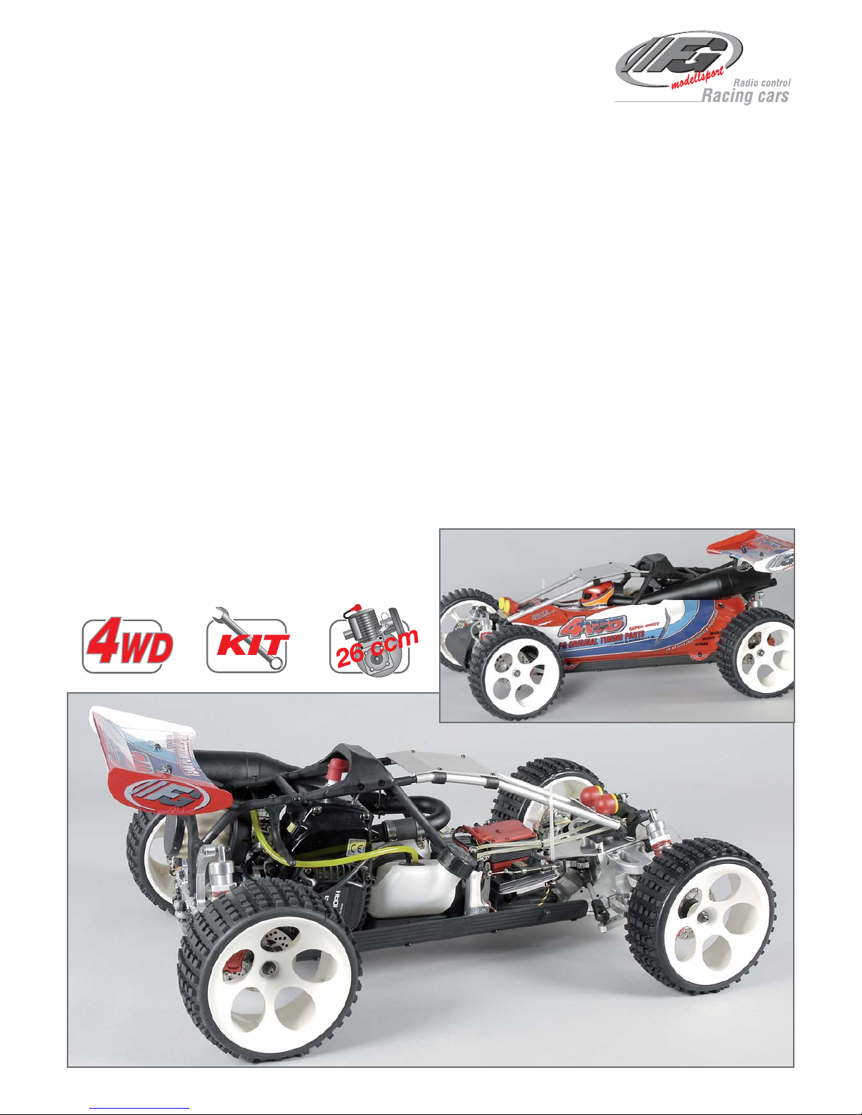
Competition 4WD Off-Road 1:6 Baja Buggy
Item No 66000, 66001
E.66000-66001-271008
Please thoroughly keep this construction instruction for spare parts’ orders!
FG Modellsport-Vertriebs-GmbH
Spanningerstr. 2
73650 Winterbach-Germany
Phone: +49 7181 9677-0
Fax: +49 7181 9677-20
info@fg-modellsport.de
www.fg-modellsport.de
Weight of the individual bags/boxes:
Item No 66000, 66001
Bag A = 1 part
Bag B = 0.771 kg
Bag C = 0.931 kg
Bag D = 1.085 kg,
Bag E = 0.407 kg
Bag F = 0.900 kg
Bag G = 0.191 kg
Bag H = 0.383 kg
Bag I1 = 0.490 kg, only for 66000
Bag I2 = 0.499 kg, only for 66001
Bag J = 0.117 kg
Bag K = 0.343 kg
Bag L = 0.343 kg
Bag M = 0.285 kg
Bag N1 = 0.027 kg, only for 66000
Bag N2 = 0.038 kg, only for 66001
Bag O = 0.299 kg
Bag P = 0.239 kg
Bag Q = 0.604 kg
Bag R = 0.397 kg
The RCS accumulators and battery charger are not included in the
delivery volume.
We congratulate you on buying this FG Competition model. Please check the contents of
the construction set, respectively of the bags. The individual bags had been thoroughly
packed by us and their weight and content had been checked. When purchasing the individual bags, please check their weight and their closure by staples which must not have
been removed or opened and closed several times. It is possible that the weight of an individual bag deviates by 5 grams. In case of claims due to missing parts, you always need to
present the label indicating the weight at your specialized dealer. By checking the weight of
the bag, you may exclude that larger parts or several parts are missing.
Are you interested in receiving 4WD news?
For example information about meetings,
races, technical hints. Just send us an email
with your name and email address to
marketing@fg-modellsport.de. You will receive
the 4WD news automatically when available.

Comments regarding the construction manual:
Before starting the assembly please see through this construction
manual. This way you will get an overview of the whole execution.
Please check by means of the parts or bag list if the construction kit is
complete and also check the weight of the individual bags for the positions. Only this way you may be sure that all parts which you need for
the assembly are available. If a part is missing, please immediately contact your specialized dealer.
Contents
Position 1-2: Front and rear differential gear
Position 3-8: Belt drive, belt stretcher, chassis structure
Position 9-15: Rear axle
Position 16-17: Front and rear shock absorber
Position 19-25: Front axle, front bumper
Position 26-32: Engine, clutch, gear , air filter, tank
Position 33-40: RC-plate, receiver box, servo saver
Position 41-45: Roll cage, throttle rods, tuning pipe
Position 46-52: Front and rear tuning disk brake
Position 53-59: Front and rear FG Magura hydr. brake system
Position 60-61: Side guards, front roll cage
The handling with fuels requires circumspective and careful handling. Imperatively observe the security advices.
-Refuel only if the engine is switched off!
-Take off the body.
-Thoroughly clean the area around the fuels nipple.
-Remove the fuel filler cap and carefully fill in the fuel mixture.
-Smoking or any kind of open fire is not admitted.
-Fuels might contain solvent-like substances. Avoid contact with skin
and eyes. Wear gloves for refueling. Do not inhale fuel vapors.
-Do not spill any fuel. If you have spilled fuel immediately clean the
engine and the model.
-Make sure that no fuel will get into the soils (environmental protection).
Use an appropriate mat.
-Do not refuel in enclosed rooms. Fuel vapors accumulate at the soil
(risk of explosion).
-Transport and store fuels only in admitted and labeled canisters. Keep
fuel out of the range of children.
-The operator is responsible for any damages caused to third persons
in the operating range of the model, respectively of the engine, if they
are injured or in case of property damage.
-The model must only be passed on to persons who are familiar with
this model and its operation, always provide the operating manual.
-Persons with implanted heart pacemakers must not work on running
engines and on live parts of the ignition system when the engine is
being started.
-The engine must neither be started nor operated in enclosed rooms
(without sufficient ventilation).
-When starting the engine, avoid inhaling the exhausts.
-The model must neither be started nor operated without air filter or
without exhaust system.
-Before every start perform a functional check of the safety-relevant
parts.
-The throttle rods must always return automatically to the idle position.
-Any cleaning, maintenance and repair works must only be performed
with the engine being switched off. The engine and silencers are getting very hot. In particular do not touch the silencer.
Our mentioned setting dimensions of steering linkage, wishbone thread
rods aso. are just guiding values which should be modified according
to the track conditions and surfaces.
Chassis adjustments and technical advices
Competition 4WD Off-Road 1:6 Baja Buggy
Our recommended chassis adjustments give you a basic setup. As the
surfaces in the Off-Road sector can be very different certain readjustments may be necessary. This depends on outdoor temperature, on
the roadbed and how strong the track is frequented.
Wheel camber:
Trailing effect:
Toe-in:
Damper springs:
Spring camber:
Damper position:
Damper piston:
Damper oil:
Stabilizer:
Driving height/ Chassis height:
Servo saver:
0° at chassis 90° rebounded
4-6mm clips
slightly open to the front
violet Item N°. 66305
5mm
Wishbone medium boring
5-hole aluminium ø1,9mm Item N°. 06484/05
2000-3000 FG damper oil
Sway bar 4mm
40mm with Baja wheels
Medium hole, outer hole position
0° at chassis 90° rebounded
3°
red Item N°. 66303
10mm
Lower wishbone outer boring
Rear alloy dampler plate outer boring
5-hole aluminium ø1,9mm Item N°. 06484/05
2000-3000 FG damper oil
Sway bar 5mm
45mm Baja wheels
Front axle Rear axle
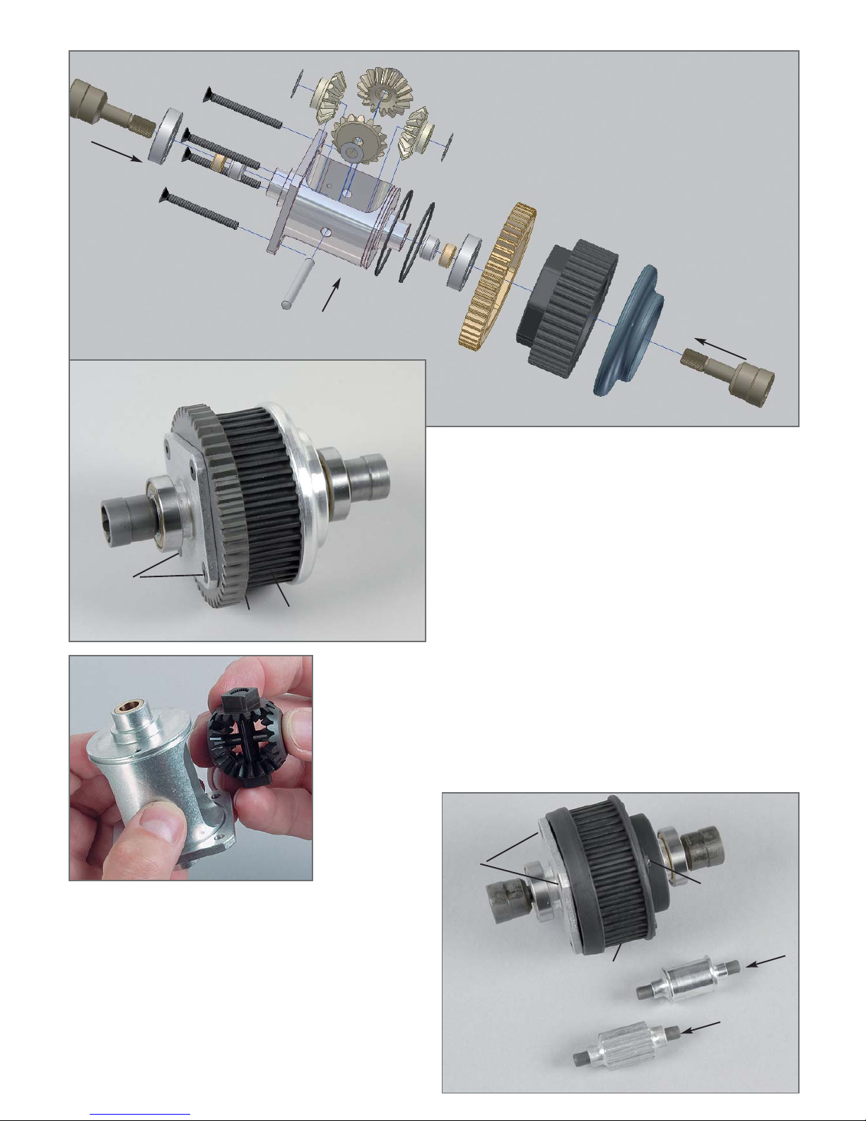
1. Insert the diff. gearwheels in the diff. housing as described in position 1. When using the FG mounting tool item No 08505, the inserting
of the bevel gearwheels will be eased considerably.
2. Lubricate the ball diff. driving axles slightly with grease and push it
in the diff. housing.
3. Mount the diff. bevel gear axle. If the bevel gear axle respectively the
driving axles can only be pushed in severely or if it cannot be pushed
in at any position, you have to dismantle the bevel gearwheels again.
Then insert it again.
4. If the gearwheels have too much clearance, correct it using the
enclosed shim rings. Please make sure that the gearwheel clearance
had not been set too close.
5. Lubricate the gearwheels slightly with multipurpose grease, e.g. item No
06501
6. Put the parts on the alloy diff. housing as described in position 1
and in the given sequence: O-ring large, O-ring small, steel gearwheel
48teeth., rear plastic gear disk 42 teeth, right alloy stop disk. Fasten
the complete unit using the M4x40 countersunk screws
(use the screw retention high-strength).
1. Mount the differential gear for the front axle as described in position
1 under the item 1-5.
2. Then put the parts on the alloy diff. housing as described in position
2 and in the given sequence: O-ring large, O-ring small, front plastic
stop disk left, plastic toothed belt wheel 42 teeth, right plastic stop
disk. Fasten the complete unit using the M4x40 countersunk screws
and the stop nuts M4.
3. Push the bearing shafts 6x50mm centrally in the deflection roller
16mm and in the 12-teeth toothed belt wheel.
Toothed belt
wheel
12 teeth
Bearing
shaft
6x50
Bearing shaft
6x50
Deflection roller
16mm
Front
plastic stop
disk left
Front plastic
toothed belt wheel
42 teeth
Front drive
Right plastic
stop disk
Position 1
Parts are in
bag B
Position 2
Parts are in
bag C
Differential rear
Rear drive
Ball diff.
driving axle
Ball bearing
15x28x7
Screw
M4x40
Needle
bearing f.
Diff
Bronze
bush
Alloy
differential
housing
Diff. bevel
gear axle
O-rings
Shim ring
5x17x0.1
Shim ring
8x20x0.1
Diff. gearwheel B
Diff. gearwheel A
Steel gearwheel
48 teeth
Rear plastic gear disk
42 teeth
Alloy stop disk
right
Chamfer
inbound
Ball diff.
driving axle
Ball bearing
15x28x7
Screw
M4x40
Alloy
differential
housing
Steel gearwheel
48 teeth
Rear plastic
gear disk
42 teeth
Alloy stop disk
right
Stop nut M4
Inserting of the diff.
bevel gearwheels or
of the complete
package is much
easier if you use the
FG mounting tool
8505.
Screw
M4x40
All metric screws need to be secured with thread lock fluid.
Toothed belt wheel
12 teeth
Left
front axle
housing
Left alloy
front axle
housing
Right alloy
front axle
housing
Ball bearing
6x16x6
Toothed belt
Toothed belt
Toothed belt
Alloy chassis
Alloy chassis
Deflection roller
16mm
Rear
differential
gear
Alloy rear axle mount
left
Alloy rear axle
mount left
Upper part
belt channel
Lower part
belt channel
Front differential
mounted
Front
differential gear
Screw
M4x14
Screw
M4x14
Position 3
Parts are in
bag C
Position 4
Parts are in
the bags A,C
Position 5
Parts are in
bag B
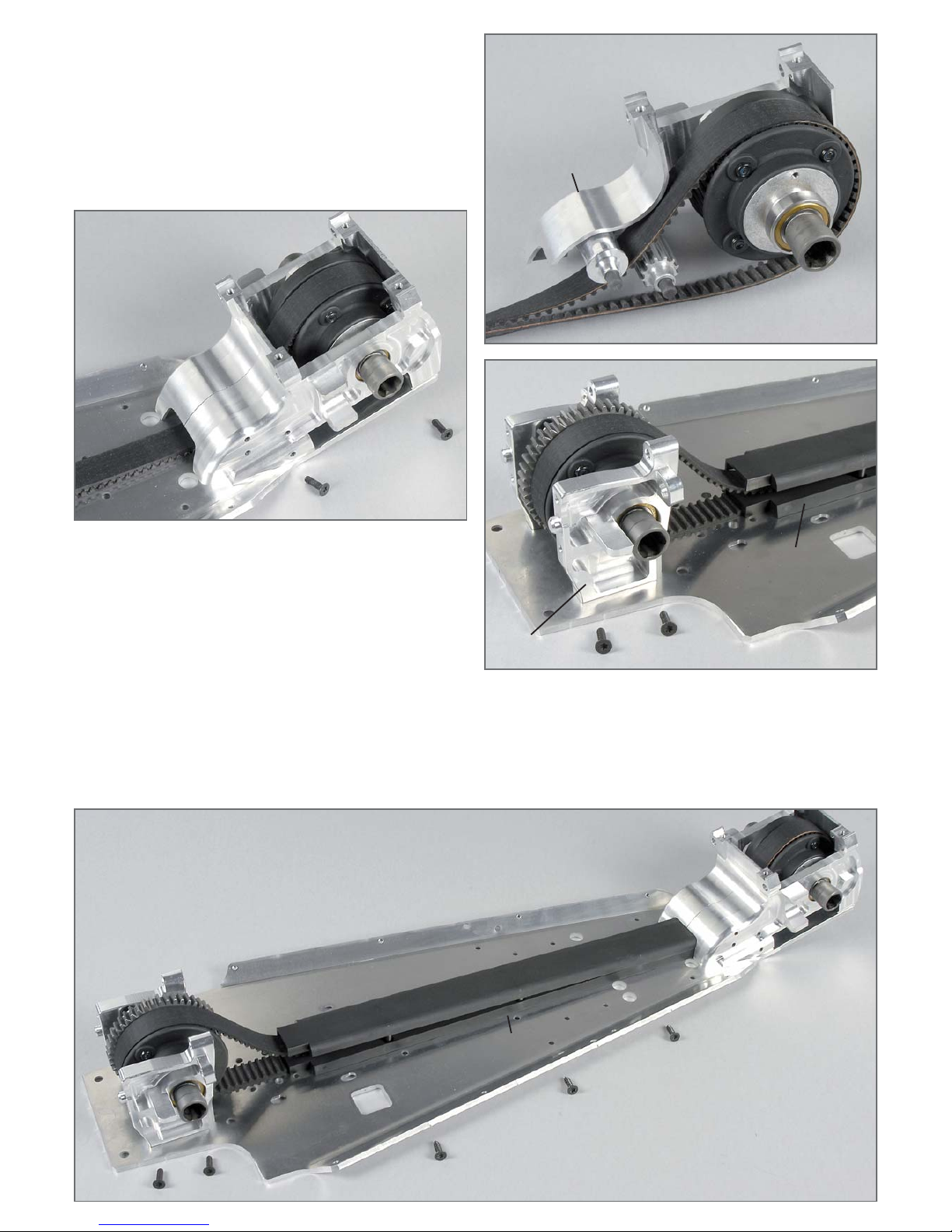
1. Push the front differential gear, deflection roller 16mm, toothed belt
wheel 12 teeth in the left alloy front axle housing as described in
position 3.
2. Put the toothed belt on the front differential gear, deflection roller
16mm and the toothed belt wheel with 12 teeth as described in position 3.
3. Press the right alloy front axle housing on the front differential gear,
deflection roller 16mm and the toothed belt wheel with 12 teeth
(position 4).
4. Put the complete alloy front axle housing on the alloy chassis and
fasten it using the M4x14 countersunk screws.
1. Put the toothed belt on the rear differential gear as described in
position 5.
2. Press the left and right rear axle mounts on the ball bearings of the
rear differential gear as described in position 5.
3. Put the left and right alloy rear axle mounts on the alloy chassis and
mount it using the M4x14 countersunk screws.
Alloy chassis
Upper part
belt channel
Lower part
belt channel
Screw
M4x14
Screw
4.2x16
Position 6
Parts are in
bag C
Toothed belt
Left alloy
front rear
axle
housing
Right alloy
front rear
axle
housing
1. Put the lower part of the belt channel on the lower part of the too-
thed belt as described in position 6. Then push the upper part of the
belt channel in the lower part of the belt channel. Then insert the complete belt channel in the opening of the alloy front axle housing. Make
sure that the toothed belt is running smoothly.
2. Mount the belt channel to the alloy chassis using the 4.2x16
countersunk screws.
Screw
M4x14
Disk
Ø4.3
Left stretching pulley
housing
Toothed belt
wheel 42 teeth
Toothed belt wheel
40 teeth
Right stretching
pulley housing
Collar
Plastic bearing
seat
Ball bearing
10x19x7
Bearing shaft f.
housing for
stretching pulley
Position 7
Parts are in
bag B
Alloy chassis
Screw
M4x14
Stretching
pulley
housing
Belt channel
mounted
Position 8
Parts are in
bag B
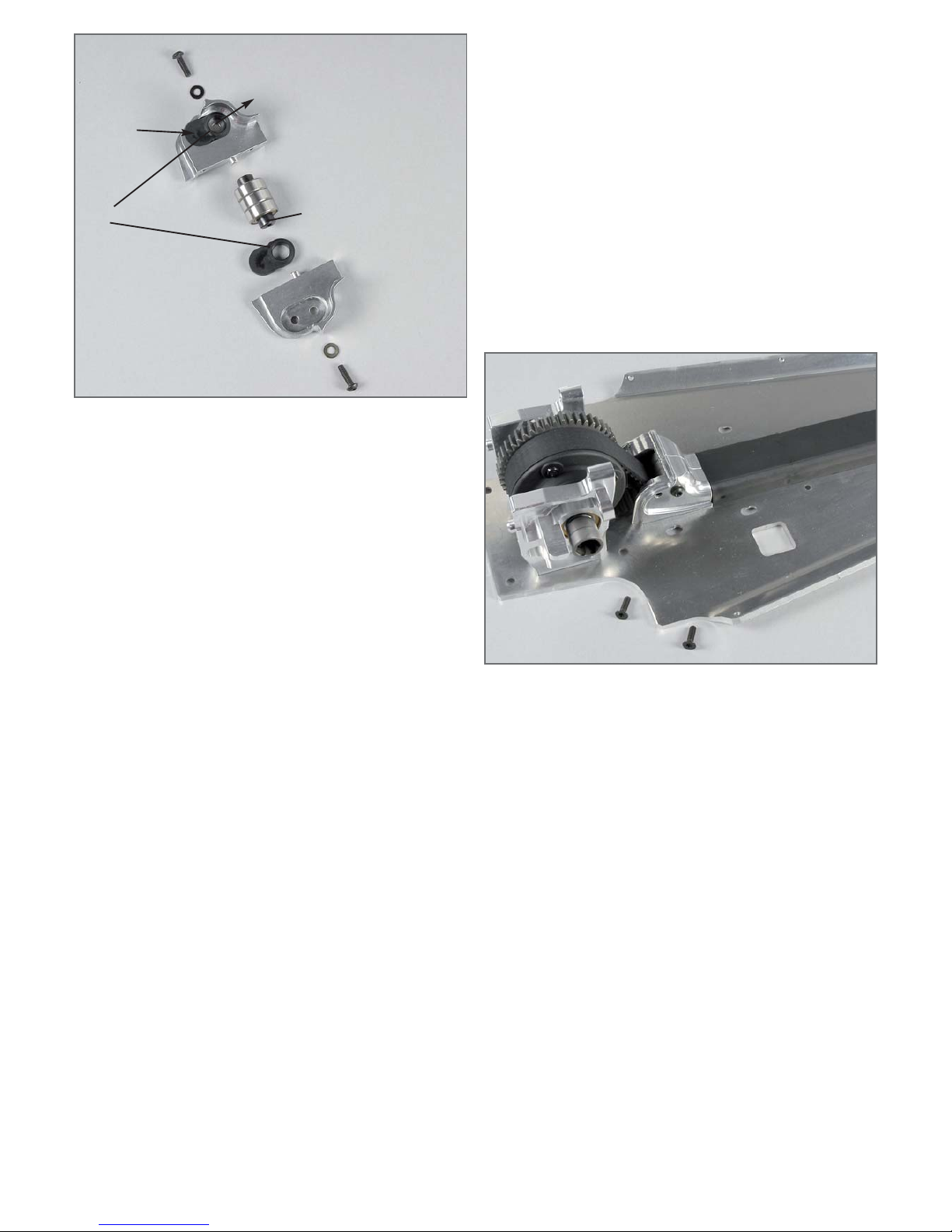
1. Push the bearing shaft for the stretching pulley housing centrically in
the 3 ball bearings 10x19x7.
2. Push the plastic bearing seat with inbound collar in the left and right
stretching pulley housing as described in position 7.
3. Push the bearing shaft which is equipped with ball bearings in the left
and right stretching pulley housings which are equipped with plastic
bearings seats and mount it using M4x14 pan-head screws and disks
Ø4.3.
4. Put the complete stretching pulley housing on the belt and belt
channel as described in position 8 and mount it on the alloy chassis
using the M4x14 countersunk screws. For this purpose, slightly move
the belt.
5. When the assembly is performed, turn the belt in running
direction. The belt has to rotate easily.
Hint: The position of the front bearing seat is made for the front plastic
toothed belt wheel with 42 teeth. The position of the rear bearing seat
is made for the rear plastic toothed belt wheel with 40 teeth.
All metric screws need to be secured with thread lock fluid.
Screw
M5x25
Taper disk
4x Screw Ø5.3 and 1x
screw M5x30
Taper disk
Stop nut M5
Push in guide
bushes
Position 10
Parts are in
bag D
1. Push the rear axle cover between the alloy rear axle mounts and
mount it using an alloy connection brace, a M4x20 pan-head screw
and a disk Ø4.3.
2. Push the guide bushes with collar in the rear lower alloy wishbones
from inside and outside.
3. Mount the M4x25 cylinder screws with stop nuts M4 and disks Ø4.3 in
the rear lower alloy wishbones.
4. Screw the hexagon nuts with M8 left-handed thread on the adjusting
screws 32mm and screw it in the rear lower alloy wishbones, then screw
the hexagon nuts with M8 right-handed thread and alloy ball bearings on
the adjusting screws 32mm.
5. Mount the plastic brace for the stabilizer to the rear lower alloy
wishbone using M3x16 pan-head screws, then push the stabilizer 5mm
in the plastic brace for the stabilizer.
6. Mount the pre-assembled rear lower alloy wishbones to the front
alloy ball-and-socket joints with M5x30 countersunk screws, 4 disks
Ø5.3 and one taper disk each between the alloy ball-and-socket joints
and mount
it to the alloy chassis using M5 stop nuts. Then mount the rear alloy
ball-and-socket joints with M5x25 countersunk screws and one taper disk
each between the alloy ball-and-socket joints and mount it to the alloy
chassis using M5 stop nuts. The mounted wishbones should move easily
up and down.
Hint: Mount taper disks always with the thinner side towards the alloy
ball-and-socket joint.
Alloy chassis
Screw
M4x20
Disk Ø4.3
Screw
M5x25
Screw
M5x30
Screw
M3x16
Screw
M4x25
Stop nut
M4
Disk Ø4.3
Disk Ø5.3
Rear lower alloy
wishbone
Alloy
connection
brace
Stabilizer
5mm
Rear axle
cover
Taper disk
Taper disk
Plastic brace for
stabilizer
Alloy balland- socket
joint
Hexagon nut M8
left-handed thread
Hexagon nut M8
right-handed thread
Adjusting screw
r/l 32mm
Stop nut
M5
Guide bush
with collar
Position 9
Parts are in
bag D
All metric screws need to be secured with thread lock fluid.
ca. 15,5mm
ca. 13-14mm
Square
wheel driver
14mm
Balls for driving shaft
Adjusting clips
Retaining
washer
Wishbone pin
Ball driving
axle
Ball driving
shaft
Protection
bellow
Distance
disk
Hexagon
nut
Headless
pin M6x6
Thread
pin M3x3
Alloy
upright
left
Disk Ø4.3
Screw
M4x8
Screw
M4x8
Use screw retention
high-strength
Screw
M4x20
Screw
M4x20
Guide bush
with collar
Guide bush
with collar
Guide bush
decentered
Guide bush
decentered,
boring
towards bottom
Rear alloy
shock mount
Alloy rear axle
mount right
Rear lower alloy
wishbone
Bearing
8x22x7
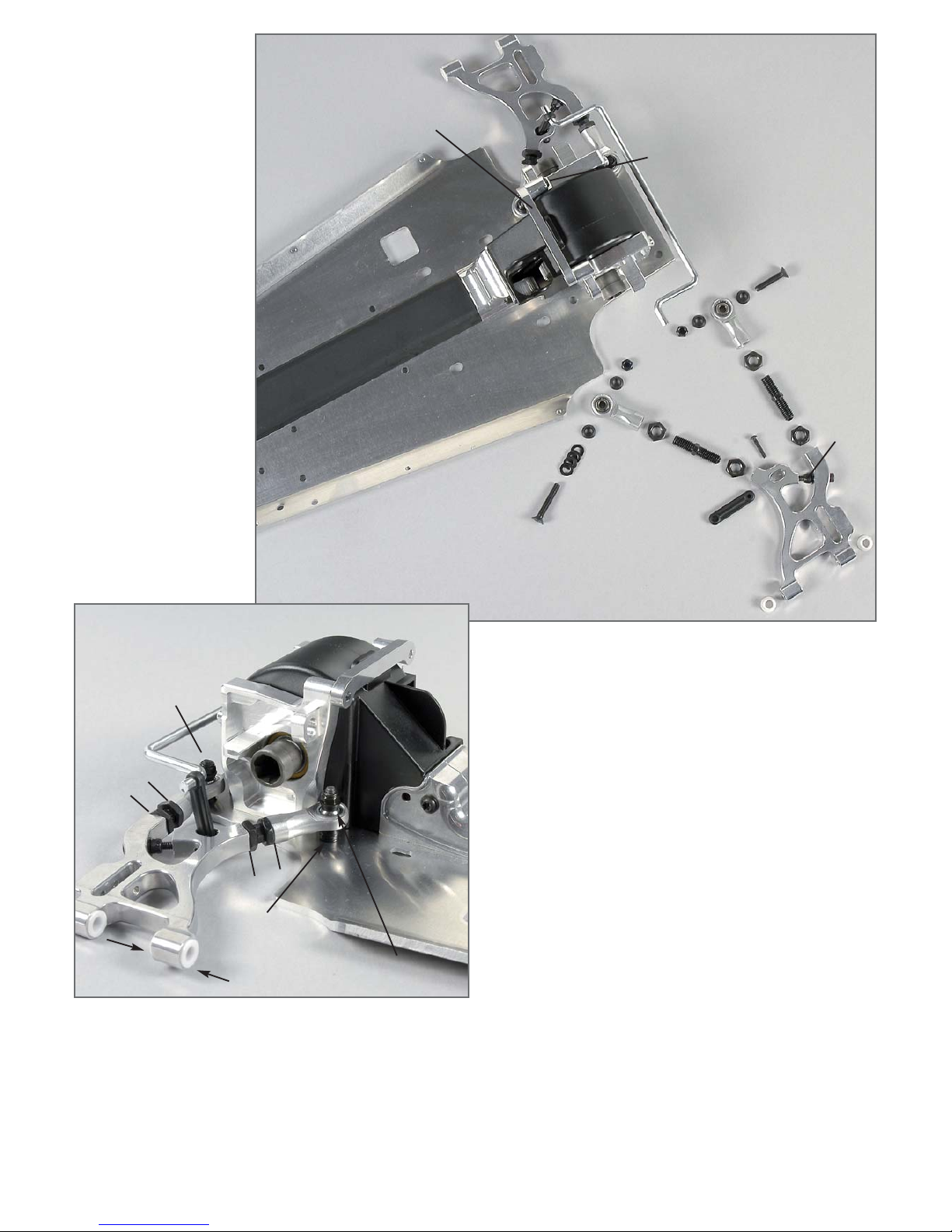
1. Mount the rear alloy shock mount to the left and right alloy rear axle
mount using the M4x20 pan-head screws.
2. Push the stabilizer in the rear alloy shock mount and fasten it using
M4x8 pan-head screws and disks Ø4.3.
3. Push the guide bushes with collar from the interior side into the left
and right alloy rear axle mounts. Push the decentered guide bushes with
boring showing to the bottom from the interior side in the rear alloy shock
mount.
4. Mount the ball driving set as described in position 12.
5. Push the ball driving axles in the alloy uprights which are equipped
with ball bearings and mount the square wheel driver 14mm with
recess towards the ball bearing to the surfaces of the ball driving axles
using M6x6 headless pins (use a high-strength screw retention).
6. Push the alloy uprights and headless pins in the rear lower alloy
wishbones as described in position 13. Secure the headless pins using
Ø5 retaining washers.
7. Put two adjusting clips each on the headless pins between the front
alloy uprights and between the rear lower alloy wishbones. Secure the
alloy uprights using M3x3 headless pins. Check if the alloy uprights are
running smoothly.
Position 11
Parts are in
bag D
Position 13
Parts are in
bag D
Apply
lubricating
grease
Slightly lubricate the
ball driving shaft
Protection bellow
Ball diff. axle
Ball driving
axle
Distance disks
Balls for
driving shaft
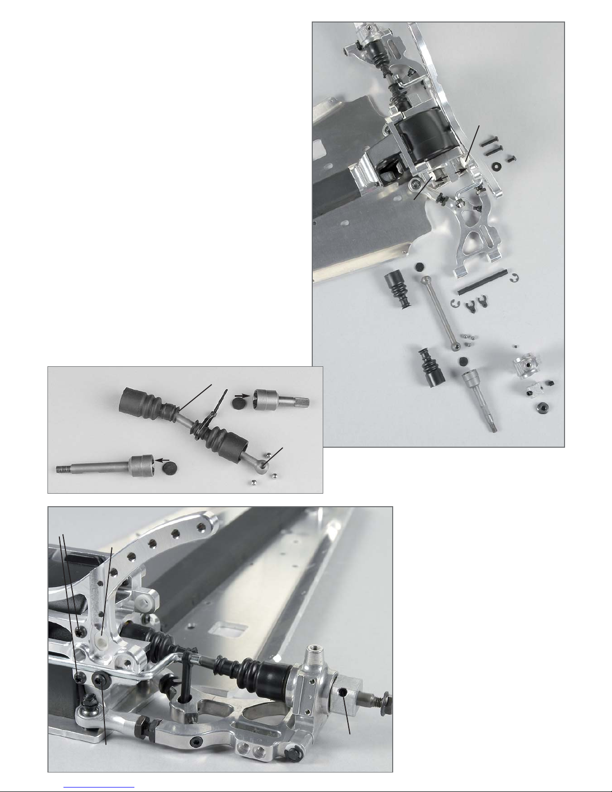
Mounting of the ball driving shafts.
Stick the distance disks in the round relief of the ball drive axle as well
as in the ball diff. axle using some multipurpose grease. Mount the
protection bellows to the ball driving shafts according to the illustration. When putting on the protection bellow, slightly grease the ball
area. Apply some lubricating grease on the ball holes and push in the
balls. The balls will be held by the lubricating grease and this way the
driving shaft can be mounted more easily. Then push the complete ball
driving shaft in the differential axle and the driving axle. Put the protection bellows on the ball diff. axles and the driving axles.
Position 12
Parts are in bag B

1. Push the guide bushes with collar in the rear
upper alloy wishbones.
2. Screw the hexagon nuts with M10 left-handed thread
on the rear wishbone thread rods M10/M8 and screw it
in the rear upper alloy wishbones, then screw the hexagon nuts with M8 right-handed thread and alloy
ball-and-socket joints on the rear wishbone thread rods
M10/M8. Use medium screw retention.
3. Push the wishbone pins throughout the alloy rear
axle mounts, rear alloy shock mount and the preassembled rear upper alloy wishbones according to
the illustration. Secure the wishbone pins using Ø5
retaining washers.
4. Push two adjusting clips each in the wishbone
pins at the front between the alloy rear axle mounts
and the rear upper alloy wishbones and push one
adjusting clip each in the wishbone pins at the rear
between the rear alloy shock mount the rear upper
alloy wishbones.
5. Mount the alloy ball-and-socket joints between the
alloy uprights and alloy ball-and-socket joints to the
alloy uprights using M5x30 countersunk screws and
taper disks. Position 15.
6. Screw M5 nuts on M5x25 headless pins and
screw it from the top in the rear upper alloy wishbones (Rebound stop travel).
Hint: The upper wishbone needs to be shimmed
according to the adjustment of the toe-in using the
adjusting clips. Always mount taper disks with the
thinner side towards the alloy ball-and-socket joint.
Adjusting clips
Adjusting clips
The upper wishbone needs to be shimmed
according to the adjustment of the toe-in
using the adjusting clips.
Retaining
washer Ø5
Wishbone pin
Headless pin
M5x25
Left alloy
uprights
Guide bush
with collar
Rear alloy
shock mount
Hexagon nut M8
right-handed thread
Hexagon nut M10
left-handed thread
Rear wishbone
thread rod
M10/M8
Rear upper
alloy wishbone
Alloy ball and sokket joint
Taper disk
Taper disk
Nut
M5
M10
M8
Screw
M5x30
Screw
M5x30
Rebound stop
travel
Position 15
Parts are in
bag D
Position 14
Parts are in
bag D
All metric screws need to be secured with thread lock fluid.
Make sure the driving shaft has not moe than 2-3mm clearance in
horizontal position. Mount enclosed disks Ø8,5/18x1,5 between
rear respectively diff.axle and ball bearing.
ca. 52mm
Screw
M4x20
Screw
M5x25
Nut
M5
Rear shock
absorber
mounted
Stop
nut
M5
Internal
silicone
tube Ø5
Shock absorber locking
Internal silicone
tube Ø4
Disk Ø3.2
Stop
nut M3
O-ring
O-ring
O-ring
Damper spring
red at the rear
violet at the front
Alloy
shock absorber
piston
Spring plate
Shock retaining
short
Threaded
piston rod long
Silicone
O-rings
Alloy
shock absorber
housing
Adjustable
ring
Sheet
gasket
Volume
compensation
Position 17
Parts are in
bag E
Position 18
Parts are in
bag E
Position 16
Parts are in
bag E
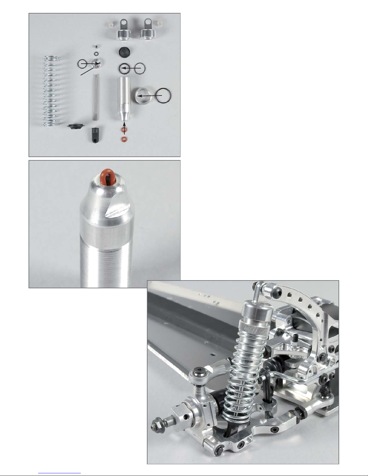
1. Insert 2 red silicone O-rings each in the alloy shock absorber housing as described in position 17.
2. Insert the black O-rings in adjustable rings and screw the adjustable
rings on the alloy shock absorber housing.
3. Mount the O-rings with the smaller groove towards the threaded
piston rod to the alloy shock absorber pistons using a disk Ø3.2 and a
stop nut M3.
4. Carefully insert the threaded piston rods throughout the alloy shock
absorber housings, without damaging the silicone O-rings. Screw the
short shock retaining in the thread of the threaded piston rod until
there is no thread visible anymore.
5. Mount the O-rings to the sheet gaskets and push it in the alloy
shock absorber housing.
6. Fill the alloy shock absorber housing with oil up to about 3mm
below the sheet gasket. Carefully slide the threaded piston rod several
times in and out of the alloy shock absorber housing, so that the air
bubbles in the oil will come up. If no longer air bubbles are coming up,
push the threaded piston rod slowly in the alloy shock absorber housing until there is only visible about 5mm of the piston rod. Then insert
the volume compensation with cambering towards the oil and screw it
down with the shock absorber locking. If too much oil is filled in it
might leak through the thread.
7. Mount the red damper springs for the rear axle to the shock
absorbers with the larger boring in the shock absorber locking and
secure it using spring plates. Proceed in the same way for the front
shock absorbers with the smaller borings in the shock absorber lokking and the violet damper springs.
8.Mount the rear lower mounted shock absorbers to the rear lower
alloy wishbones using M4x20 cylinder screws. Screw M5x25 pan-head
screws in the rear alloy shock mount and counter it using M5 nuts,
then mount the upper shock absorber with internal silicone tube Ø5
and M5 stop nuts.
Hint: Slightly lubricate the silicone O-rings and the threaded piston
rods when mounting. If the FG mounting tool item No 06853 is used,
the mounting of the shock absorbers will be eased considerably.
Rear alloy
damper plate
 Loading...