

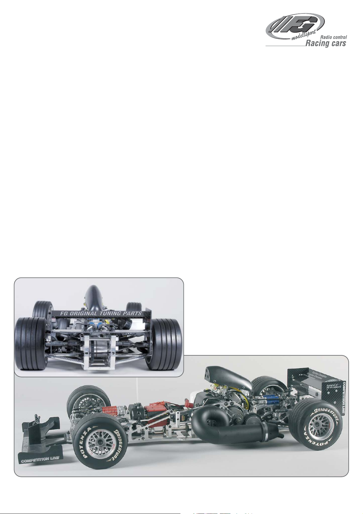
Mounting instruction for
F1 Competition 09 Chassis
Item N°. 10007, 10008
A.10007-10008-200409
FG Modellsport GmbH
Spanningerstr. 2
73650 Winterbach-Germany
Phone: +49 7181 9677-0
Fax: +49 7181 9677-20
info@fg-modellsport.de
www.fg-modellsport.de
Please thoroughly keep this construction manual for spare parts orders!
Weight of the individual bags/ boxes:
Bag A = 4 parts
Bag B = 0,871 kg
Bag C = 0,649 kg
Bag D = 0,617 kg
Bag E = 0,308 kg
Bag F = 0,136 kg
Bag G = 0,699 kg
Bag H = 0,729 kg
Bag I = 0,091 kg
Bag J = 0,125 kg
Bag K = 0,498 kg
Bag L = 0,442 kg
Bag M = 0,502 kg
Bag N = 0,355 kg
Bag O = 0,587 kg, only for Item N°. 10007
Bag P = 0,447 kg, only for Item N°. 10008
The RCS, accumulators and battery charger are not included in the delivery volume.
We congratulate you on buying this FG Competition model. Please check
the contents of the construction set, respectively of the bags. The individual bags had been thoroughly packed by us and their weight had been
checked. When purchasing the individual bags, please check their weight
and their closure by staples which must not have been removed or opened and closed several times. It is possible that the weight of an individual bag deviates by 5 grams. In case of claims due to missing parts, you
always need to present the label indicating the weight at your specialized dealer. By checking the weight of the bag, you may exclude that larger parts or several parts are missing.

The handling with fuels requires circumspective and careful handling. Imperatively observe the security advices.
- Refuel only if the engine is switched off!
- Take off the body.
- Thoroughly clean the area around the fuels nipple.
- Remove the fuel filler cap and carefully fill in the fuel mixture.
- Smoking or any kind of open fire is not admitted.
- Fuels might contain solvent-like substances. Avoid contact with skin and eyes. Wear gloves for refueling. Do not inhale fuel vapors.
- Do not spill any fuel. If you have spilled fuel immediately clean the engine
and the model.
- Make sure that no fuel will get into the soils (environmental protection). Use
an appropriate mat.
- Do not refuel in enclosed rooms. Fuel vapors accumulate at the soil (risk of
explosion).
- Transport and store fuels only in admitted and labeled canisters. Keep fuel
out of the range of children.
- The operator is responsible for any damages caused to third persons in the
operating range of the model, respectively of the engine, if they are injured
or in case of property damage.
- The model must only be passed on to persons who are familiar with this model and its operation, always provide the operating manual.
- Persons with implanted heart pacemakers must not work on running engines and on live parts of the ignition system when the engine is being started.
- The engine must neither be started nor operated in enclosed rooms (without sufficient ventilation).
- When starting the engine, avoid inhaling the exhausts.
- The model must neither be started nor operated without air filter or without
exhaust system.
- Before every start perform a functional check of the safety-relevant parts.
- The throttle rods must always return automatically to the idle position.
- Any cleaning, maintenance and repair works must only be performed with
the engine being switched off. The engine and silencers are getting very
hot. In particular do not touch the silencer.
Comments regarding the construction manual:
Before starting the assembly please see through this construction manual.
This way you will get an overview of the whole execution.
Please check by means of the parts or bag list if the construction kit is complete and also check the weight of the individual bags for the positions. Only
this way you may be sure that all parts which you need for the assembly are
available. If a part is missing, please immediately contact your specialized
dealer.
Table of contents
Position 1: Differential gear
Position 2-7: Rear axle, gearwheel drive
Position 8: Shock absorber
Position 9-10a: Assembly shock absorber, stabilizer - rear axle
Position 11-19a: Front axle
Position 14-17: Servos, receiver
Position 18-19a: Assembly shock absorber, stabilizer - front axle
Position 12-13: Servo saver, track rods, steering rods
Position 19-23: Engine, manifold, airbox, clutch
Position 23-24a: Engine assembly, tank
Position 25-25a: Tuning pipe
Position 18: Throttle rods
Position 28-29: Front spoiler, rear spoiler
Position 30-31b: FG Magura hydr. brake system front and rear
Position 32-33b: Tuning disk brake front and rear
All metric screws need to be secured
with thread lock fluid.
7080/3
6069/2
8600/13
8600/3 8600/4
8602/1
8493
8600/11
8602/2
8600/13 8600/13
8602/2
8600/2
8600/13
8600/9
8600/10
8493
6924/20
6069/2
7080/3
6924/20
8600/8
6067
6068
8500/3
6067
8600/8
8600/11
8600/1
8600/11
8600/6
Steel gearwheel
large 48t.
Screw M4x8
Flat side
O-ring
Ball diff.
axle
Assembly
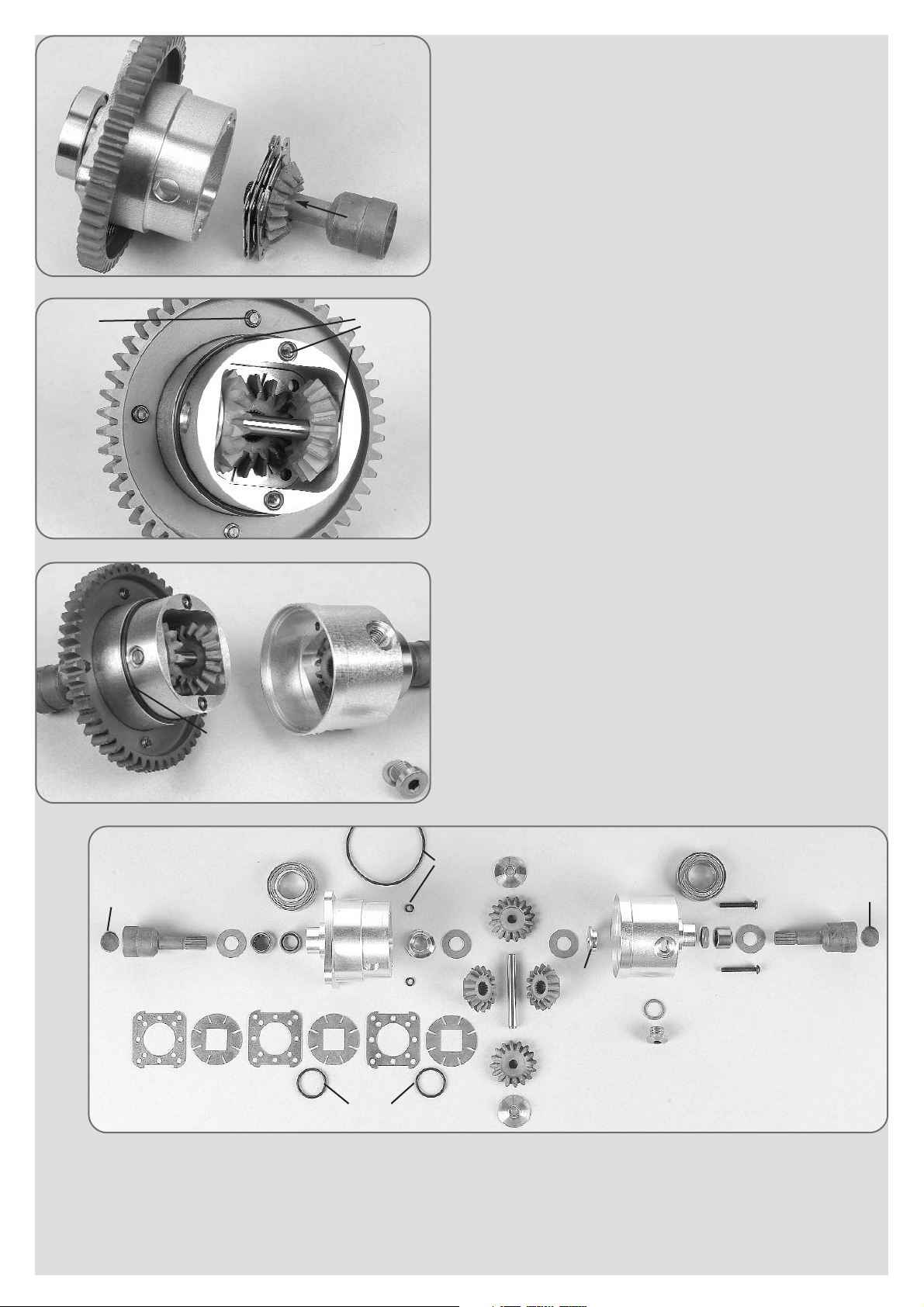
The flange bushes 8602/2, roller bearing 8602/1 as well as the rotary shaft seals 8600/6 and the ball bearing 8493 have professionally been mounted on
the alloy differential housing A/B by the manufacturers FG .
Now mount the steel gearwheel 48 teeth on the alloy differential housing A.
Check the internal and external fins on production birs, if necessary remove
them with an emery cloth. Do not bend the fins.
Now mount the set of fins according to illustration 1: Insert a differential gearwheel with square on a differential bevel wheel axle. Then slide on the
square one after another in the following order 1x internal fin, 1x O-ring 14x1.5,
1x external fin, 1x internal fin, 1x O-ring 14x1.5, 1x external fin, 1x internal fin,
1x external fin. Grease the shim ring 8600/13 a little and put the differential
housing on the flange bush 8602/2. Now insert the whole package into the
differential housing A according to the illustration. Now push the differential
gearwheel with a screw driver with the fin package towards the housing and
carefully pull out the differential axle.
Push both bronze bushes 8600/8 from the inside to the outside into the borings of the differential housing, position 1a. Insert the differential gearwheels
B into the housing and push in the differential bevel differential gear axle
6068. Grease the 8mm shaft of the ball diff. axle 6069/2 plentifully and push
it from outside into the differential housing. The borings of the alloy differential housing need to align with the borings of the differential gearwheels.
If the borings are offset, the gearwheels need to be disassembled and reassembled once again displaced by one tooth until the parts can be easily turned. Mount the O-rings 3x1 and 42x1.5 according to the illustration.
Now join the two halves of the housing, check them for free movement and
assemble them using the two enclosed M3x20 screws.
Fill in about 15ml of the enclosed silicon oil into the boring of the alloy differential housing B. Add about 5ml 2-stroke engine oil for better lubrication. Then
close the boring by means of the locking screw M8x1/ copper disk. You may
influence the locking effect by the number of fins by the viscosity of the filled in oil as well as by the filling quantity.
When driving an overpressure is building up in the diff. housing. Therefore you
should unscrew the locking screw after a few laps of driving time in order to
release the overpressure.
Insert the fin package
into housing A.
O-ring 42x1,5
O-ring 3x1
Bronze bush
7x18x5
Position 1
Parts are in
bag C
Position 1b
Parts are in
bag C
Position 1a
Parts are in
bag C
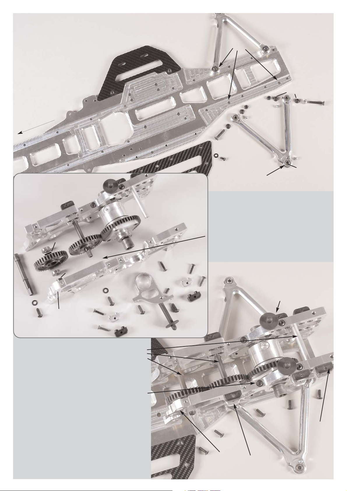
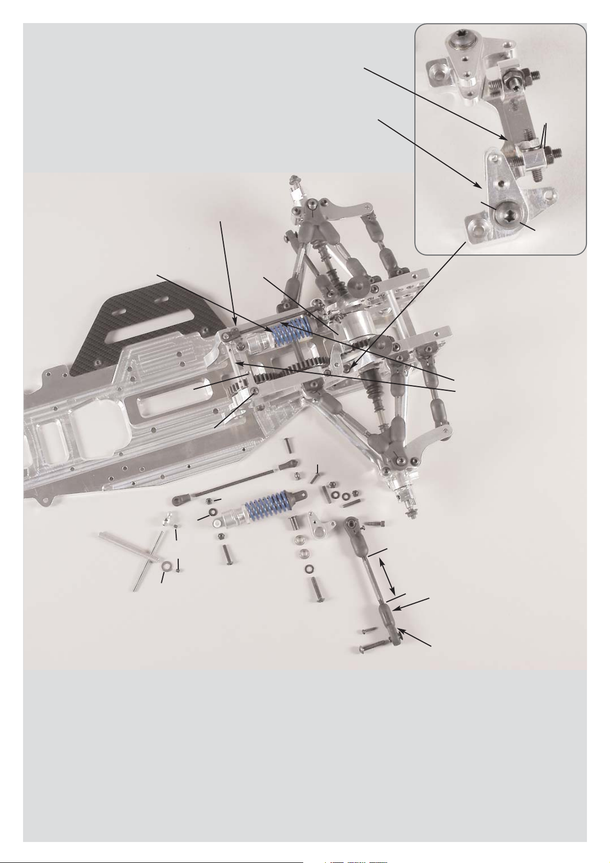
Press the bearing shafts into the right alloy rear axle mounts
and mount the alloy cross bracing with M4x18 countersunk
screws to the left and right alloy rear axle mounts.
Before assembling, impress the alloy diff. bearings into the guidings of the left and right alloy rear axle mounts and check if they
are running smoothly, it may be necessary to rework the guidings a little with an emery cloth. Then press them on the ball
bearings of the pre-assembled differential and press them in
evenly (with the gearwheel in direction to the left alloy rear axle mount) into the left and right alloy rear axle mounts. Mount the
alloy diff. bearings to the alloy rear axle mounts by using pan-head screws M5x14.
Insert the body supports in the left and right alloy diff. bearings,
align the borings for the body clips in driving direction and clamp
them by using headless pins M4x10.
Mount the complete gearwheel drive on the alloy chassis by
using M4x14 countersunk screws.
Hint: The left and right alloy diff. bearings are different, please pay
attention to the mounting direction. Make sure that the gearwheels are running smoothly. If this is not the case, look for the reason and remedy the defect, mount it again, if necessary.
Position 2
Parts are in
bag A+B
CFRP chassis
right side part
D
riv
in
g
d
ire
c
tio
n
Disk Ø 4,3
Screw 4x8
Stop nut
M5
Alloy chassis
Screw
5x25
Screw
5x30
Screw 3x6
Ball bush
Rear lower alloy
wishbone
CFRP chassis
left side part
Bevel
washer
Bevel
washer
Alloy bush
5x10x5,5
Position 3
Parts are in
bag C+D
Alloy rear axle
mount right
Ball bearing
8x16x5
Distance
bush
11x8x1
Ball bearing
8x16x5
Bearing
shaft
Gearwheeel
38 teeth
Distance
bush
11x8x6
Guide bush
Guide bush
Differential
mounted
Alu-Querverstrebung
Alloy cross
bracing
Alloy rear axle
mount left
Screw
4x18
Screw 4x18
Screw
4x18
Headless
pin 4x10
Headless
pin 4x10
Alloy wishbone fixing
M4
Alloy wishbone fixing
M4
Plastic wishbone fixing
Ø4
Plastic wishbone fixing
Ø4
Screw
4,2x19
S
cre
w
4
,2
x1
9
Left alloy
diff. bearing
Screw
5x14
Screw
5x14
Screw
5x14
Body support
Disk
Ø 5,3
Disk
Ø 5,3
Screw
5x14
Alloy chassis
Position 4
Parts are in
bag C+D
Alloy rear
axle mount
right
Alloy rear
axle mount
left
Screw
4x14
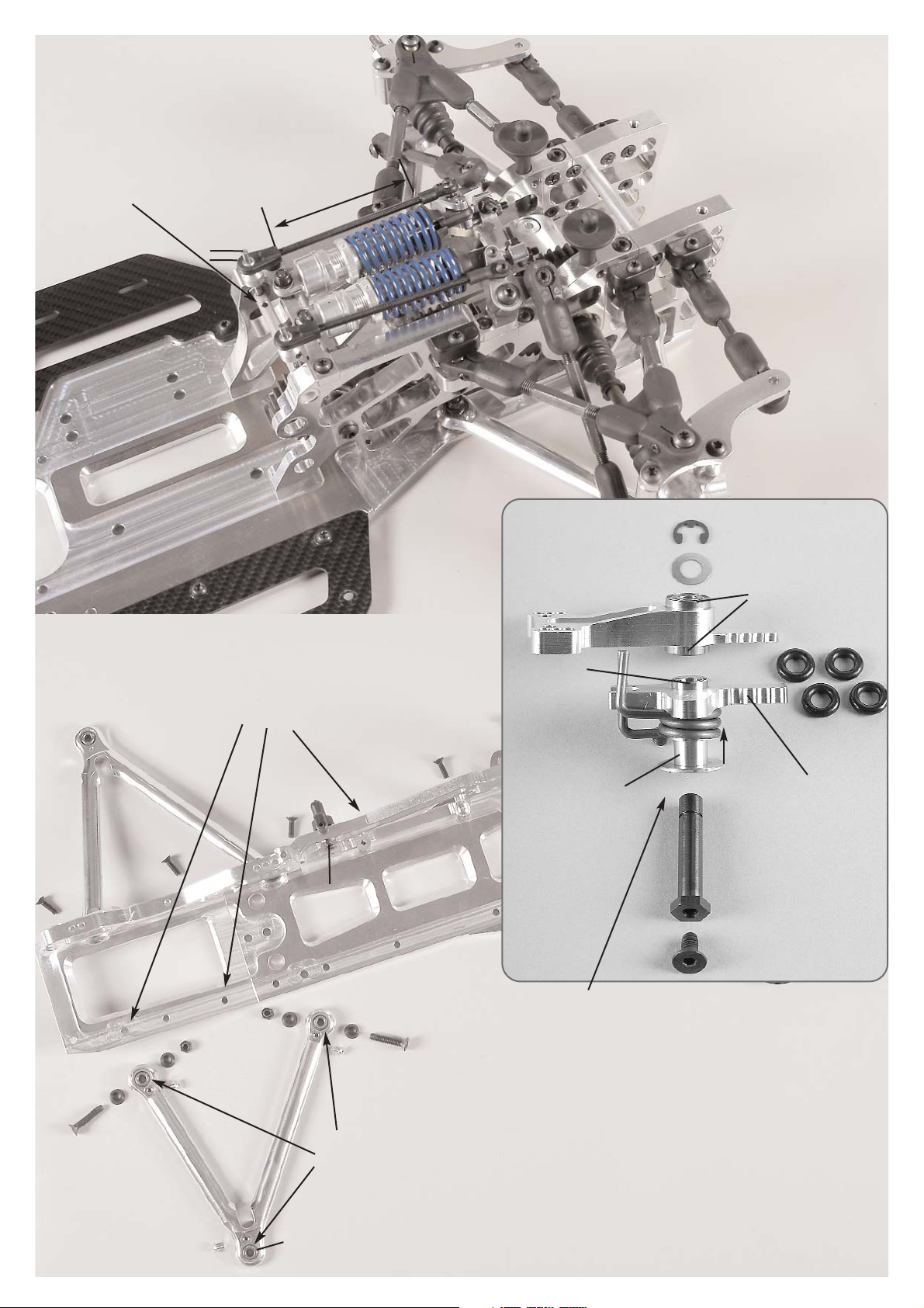
Screw the CFRP chassis side parts to the alloy chassis using M4x8 pan-head screws and
disks Ø4,3.
The CFRP chassis side parts left and right
differ, pay attention to the mounting direction.
Impress the ball bushes into the alloy
wishbones and secure them with M3x6
pan-head screws.
Mount the rear lower alloy wishbones to the front alloy chassis by using M5x25
countersunk screws, bevel washers and stop nuts M5. Fix the rear alloy wishbone by using M5x30 countersunk screws, alloy bushes 5x10x5,5 (between alloy chassis and bevel washer), bevel washers and stop nuts M5.
Mount the bevel washers always with the thinner side facing towards the ball bush.
Press the guide bushes into the alloy rear axle mounts.
Mount the lower alloy wishbone fixings M4 and the upper
plasic wishbone fixings Ø4 to the alloy rear axle mounts
by using M4x18 and 4,2x19 countersunk screws. Press
each 2 ball bearings 8x16x5 and a distance bush 11x8x1
into the gearwheels 38 teeth, then insert the bearing shafts
from the square side. Now press the bearings shafts with
the distance bushes 11x8x6 into the left alloy rear axle
mount and fix them by using M5x14 pan-head screws and
disks Ø5,3.
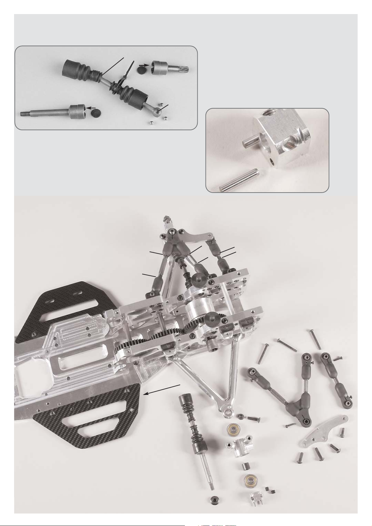
Push the distance disks into the round recess of the ball driving
axle as well as into the ball diff. axle. Mount the protection bellows to the ball driveshafts according to the illustration. Lubricate the ball range a little when putting on the protection bellow. Apply lubrication grease on the ball holes of the driveshafts and press in the balls. The balls will be held by the lubrication grease
and this way the driveshaft can be mounted more easily. Now press the complete
ball driveshaft into the ball differential axle and the ball driving axle. Shift the protection bellows over the ball diff. axles and the ball driving axles.
Position 7
Parts are in
bag B
Driving
shaft
mounted
Left alloy
upright
Headless
pin 6x6
Wheel nut
M6
Square wheel
14 mm
Screw
4x12
Distance
bush
Ball bearing
8x22x7
Ball bearing
8x22x7
Pay attention
to the slant
Screw
5x16
Screw
5x16
Screw
5x20
Rear axle
plate left
Screw
5x20
Bevel
washer
Driving direction
Track rod
mounted
Screw
2,9x13
Screw
2,9x13
Rear upper
wishbone
left mounted
Screw
4x35
Screw
4x35
Ball diff. axle
Alloy rear axle
mount left
approx.
21,5mm
approx.
39mm
approx.
10,5mm
Hint: The left and right upper wishbones are different,
mounting direction of the steel ball with collar on the
alloy upright is showing to the bottom and the shorter
side faces the rear. The clearance of the balls in the
ball-and-socket joints can be adjusted with the help of
the screws 2.9x13. The left and right rear axle plates
differ, pay attention that the slant shows to the top when
assembling.
Apply
lubrication
grease.
Lubricate ball driveshaft a little.
Protection bellow
Ball diff. axle
Ball driving
axle
Distance
disks
Balls for driving shaft
Position 5
Parts are in
bag B
1. Press the cylinder pins into the square wheel 14mm as
described in position 6, use high-strength screw retention.
Press the ball driving axles of the pre-assembled driveshafts into the alloy uprights which are equipped with
ball bearings and then mount the square wheel driver
14mm with recess facing the ball bearing on the flat side of the ball driving axle by using the headless pins
M6x6.
Mount the alloy upright between alloy upright and alloy
wishbones using a countersunk screw M5x20 and bevel
disk (thin side facing the ball bush). The left and right alloy uprights are different. The milled surface for the brake has to face the rear.
2. Mount 2,9x13 pan-head screws into all
plastic ball-and-socket joints.
Mount the pre-assembled upper wishbones
and track rods to the alloy rear axle mounts
using the pan-head screws M4x35.
Fix the rear axle plates with the slant showing
upwards to the alloy uprights by using M5x16
pan-head screws.
Mount the upper wishbones to the rear axle
plates using countersunk screws M5x20.
Mount the track rods to the rear axle plates
using cylinder screws M4x12.
Hint: The left and right track rods are different, pay attention to the balls in the ball-andsocket joints, mount the ball with lowering
using the cylinder screw.
All metric screws need to be secured with thread lock fluid.
Position 6
Parts are in
bag B

Position 8
Parts are in
bag E
Position 8a
Parts are in
bag E
Position 8b
Parts are in
bag E
Position 8e
Parts are in
bag E
Position 8c
Parts are in
bag E
Position 8d
Parts are in
bag E
Disk
Ø 4,3
Disk Ø
4,3
Rear alloy
baffle
Screw
5x25
Disk
Ø 5,3
Ball bearing
7x11x3
Headless
pin 4x20
Headless
pin 4x20
Nut
M4
Alloy damper
reversing
Alloy damper reversing
Screw the ball-and-socket joints
6mm and 7mm on the rods to the
length of approc. 72mm, then
press the steel balls 6mm and ball
collets 7mm in the same direction into the ball-and-socket joints 6mm and 7mm.
Mount the stabilizer into the ball
collets 7mm with an excess
length of approx. 8mm by using a
headless pin M4x4.
Press the stabilizer shaft with
shim rings 6x12x1 between the
alloy rear axle mounts, insert the
two stabilizer rods in the stabilizer
shaft, connect the stabilizer rods
with the shim rings between the
alloy rear axle mounts and mount
them using headless pins M4x4.
Mount the ball-and-socket joint
with steel ball 6mm to the inside
of the damper reversings using
pan-head screws M3x16. Pay attention to position 10a.
Screw
5x25
Push-Rod
mounted
Screw
2,9x13
approx.
53mm
Position 9
Parts are in
bag F
Position 10
Parts are in
bag F
Stabilizer
Stabilizer shaft
Ball collet
7mm
Ball joint
7mm
Linkage
Headless
pin 4x4
Shim ring
6x12x1
Screw
3x16
Stop
nut M4
Damper fixing
brace
Disk
Ø 4,3
Screw
4x12
Rear alloy
baffle
Screw
4x14
Disk
Ø 5,3
Screw
5x25
Ball bearing
7x11x3
Ball joint
6mm
Steel ball
6mm
Screw
4x20
Nut
M4
Screw
3x12
Bearing
bush
Nut
M4
Disk Ø
4,3
Assemble the M4x20 pan-head screws into
the damper fixing brace and secure them
with M4 nuts. Now mount the fixing brace
to the alloy rear axle mounts by using M4x12
pan-head screws and Ø4,3 disks.
Screw the M4x20 headless pins into the alloy baffle as pictured and secure them by using Ø4,3 disks and M4 nuts.
Mount the alloy baffle to the alloy rear axle mounts using
M4x12 pan-head screws.
Press the ball bearing 7x11x3 into the alloy damper reversing, insert the bearing bushes through the alloy damper reversings which are equipped with ball bearings and mount
them to the alloy baffle using M5x25 pan-head screws and
Ø5,3 disks.
Fix the rear dampers to the damper fixing brace by using Ø4,3 disks and M4 stop nuts.
Fix the front dampers from the outside at the
alloy damper reversings with M3x12 pan-head
screws.
Mount the 2,9x13 pan-head screws into the plastic ball joints of the push-rods.
Fix the pre-assembled lower push-rod
with the collar of the steel ball to the rear lower alloy wishbones by using
M5x25 pan-head screws.
Mount the pre-assembled upper pushrod to the alloy damper reversings by
using M4x14 cylinder screws.
Hint: Left and right push-rods are different, pay attention to the balls in the ball
joints, mount the ball with lowering with
the cylinder screw. An arising clearance
in the ball joints can be adjusted with
the 2,9x13 screws.
All metric screws need to be secured with thread lock fluid.
Alloy servo saver A 04
ball-beared
Alloy servo saver B 04
ball-beared
Flange sleeve for
alloy servo saver
Servo saver spring
Servo saver axle
Countersunk screw M5x25
Securing disk 6mm
Shim ring 7x13x0,3
O-rings
Ball bearing 7x14x5
Ball bearing
7x11x3
Position 12
Parts are in
bag H
approx. 8mm
a
p
p
ro
x
. 7
2
m
m
Screw
4x14
Screw
4x14
Stop nut
M5
Screw
3x6
Screw
3x6
Bevel
disk
Bevel
disk
Front axle
carrier right
Alloy chassis
Alloy front
chassis
Position 11
Parts are in bags
G+A+H
Front lower alloy
wishbone left
Ball-type
nipple
Screw
5x25
Screw
5x25
Body mount
Screw
4,2x19
Position 10a
Parts are in
bag F
The stabilizer rod should be mounted parallel to the shock absorber.
Make sure the stabilizer 3mm projects approx. 8mm at the top. Please check if the
stabilizer does not contact any other parts
when deflecting.
Secure the ball-type nipples which are moulded
in the alloy wishbones
using the binding head
screws M3x6.
Mount the front lower alloy wishbone with the shorter side facing the front to the
alloy chassis and the alloy front chassis by using M5x25 countersunk screws, bevel disks and M5 stop nuts. Mount bevel disks always with the thinner side facing
the ball-type nipple.
Fix the body mounts to the left and right front axle carriers using 4,2x19 countersunk
screws. Mount the right front axle carrier to alloy chassis and alloy front chassis
with M4x14 countersunk screws.
Push the ball bearing in the alloy servo saver parts A and B. Mount the
servo saver spring on the alloy servo saver part A, then mould the flange sleeve in the alloy servo saver part A. Press the servo saver axle
through the flange sleeve into the two servo saver parts and secure it
using the shim rings and the securing ring 6mm. Check if the servo saver is running smoothly, mount the o-rings on the servo saver.
Hint: You can adjust the effect of the servo saver with the number of the
used o-rings. The more o-rings, the harder is the effect of the servo saver.
All metric screws need to be secured
with thread lock fluid.
Servohebel
Screw
3x18
Screw
4x20
Screw
2,9x13
Ball joint
Ball joint
6mm
Alloy joint
ball
Track rod
mounted
Steering rods
mounted
Stop nut
M4
Stop nut
M3
Steel ball
6mm
Servo saver
mounted
Position 13
Parts are in
bag H
approx. 45mm
Front axle
carrier right
Screw
3x18
Screw
4,2x16
Screw
5x25
Distance
disk
Distance
bolt
Stop nut
M3
Steering servo
Steering servo
Servo fixing
brace
S
teering ro
d
s
m
o
unted
Disk Ø
5,3
Screw
4,2x19
Mount the assembled steering rods through the steel balls 6mm with
the collar facing the servo saver into the outer thread holes of the alloy servo saver by usin g M3x18 pan-head screws and secure them
with M3 stop nuts. Screw 2,9x13 pan-head screws into the plastic
ball-and-scket joints of the track rods.
Fix the mounted track rod into the front outer hole of the servo saver
by using M4x20 cylinder screws. The cylinder screw must go through
the alloy joint ball, the collar must face the alloy servo saver. Fasten
it all with M4 stop nuts.
Hint: The ball clearance can be adjusted with the 2,9x13 screws in the
ball-and-socket joints.
Steering servo
Steering servo
Servo fixing
brace
Position 14
Parts are in
bag H
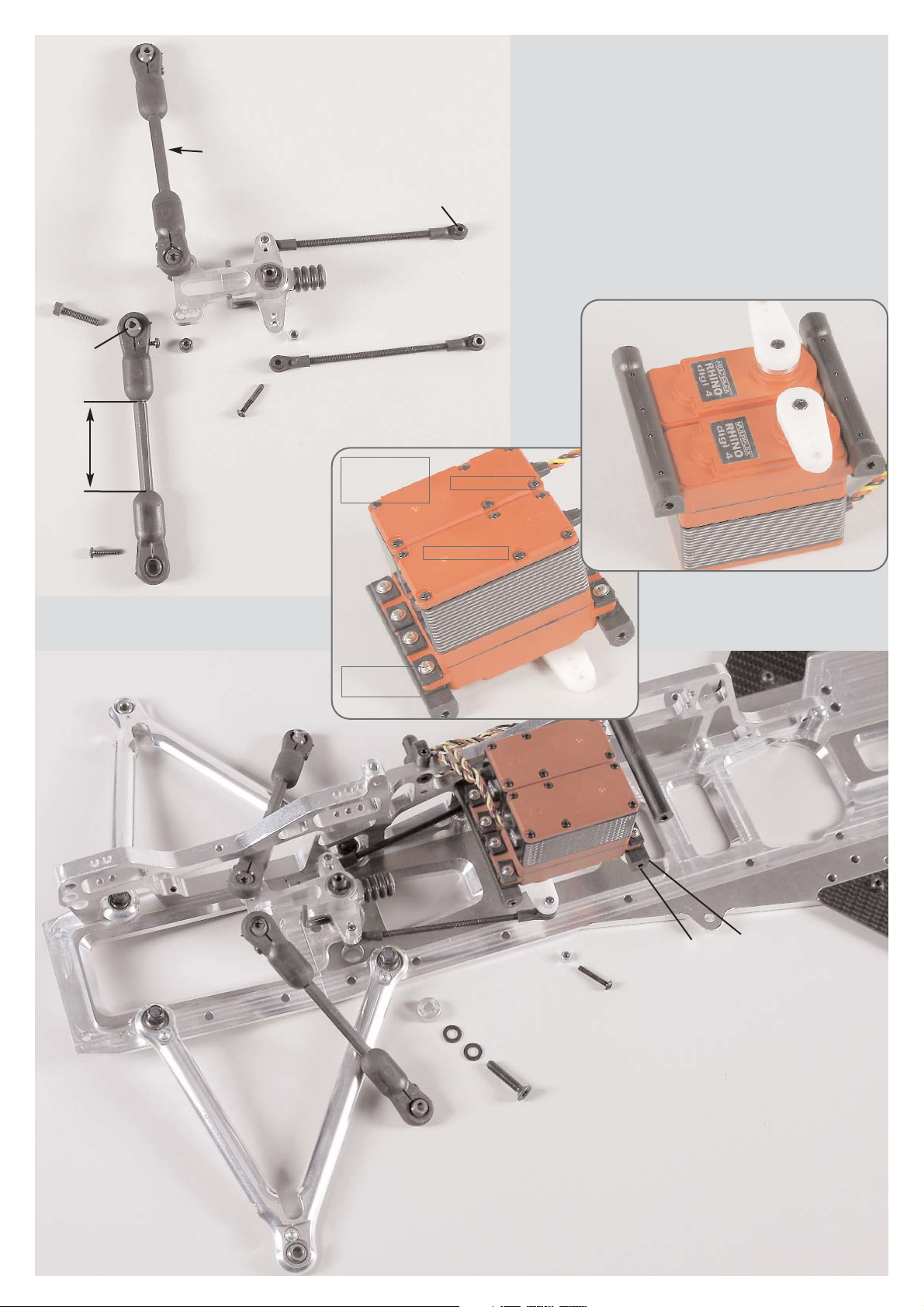
Mount the steering servos with the enclosed fixing rubber bushings and screws to the servo fixing braces as described in position 14. Switch on
your RCS and bring the steering servos in neutral position. The servo arms have to be shortened
slightly corresponding the type. For competition
we recommend to use alloy servo arms. Press the
servo arms on the servos as pictured and fix them
with the enclosed screws. Preferably the servo
arms should be in a 90° position to the servo.
Mount the servo fixing braces on the right front axle carrier by
using 4,2x16 countersunk screws.
Mount the distance bolt with a 4,2x19 countersunk screw to
the right front axle carrier.
Mount the servo saver with a M5x25 countersunk screw, Ø 5,3
disk and distance disk between servo saver and alloy chassis in the rear hole of the alloy chassis.
Switch on the RCS, bring the trim of the steering into central
position. Align servo saver in centre of the chassis. First mount
one servo rod using M3x18 pan-head screw and M3 stop nut,
then the second in the same way. Adjust both servo rods in
the same length. You should be able to fix the servo rods easily and without any resistance on the servo arms of the steering servos.
Hint: Adjust both steering rods in the same length by turning
the ball-and-socket joints. Servo saver and servo arm should
be parallel.
Servo arm
Steering servo
Servo fixing
brace
Position 14
Parts are in
bag H
Position 15
Parts are in
bag H

Disk
Ø 4,3
Front axle
carrier left
Screw
4x14
Screw
4x14
Screw
4x14
Alloy battery
fixing brace F1
Drill the alloy battery
fixing brace F1 to
7mm if using the 3rd
receiver fixing.
Alloy
chassis
Screw
2,9x13
Receiver
battery
Body mount
Body clip
Dampening
rubber
Battery/
body bolt
Screw
2,9x9,5
Screw
2,9x19
Screw
2,9x16
Receiver box
Flexible aerial
Mount for flexible aerial
Stop
nut M4
Mount the left front axle carrier to the
alloy chassis and the alloy front chassis using M4x14 countersunk screws .
Mount the servo mounting brace to the
left front axle carrier using 4.2x16
countersunk screws. Mount the distance bolt to the left front axle carrier
using a 4.2x19 countersunk screw.
Mount the throttle-brake servo and the
brake servo to the front axle carrier
using M2.5x12 pan-head screws.
Drill out the aerial hole by 3mm at the
lid of the receiver box and mount the
aerial mount to the lid of the receiver
box using a 2.9x19 pan-head screw.
Insert the flexible aerial through the flexible aerial mount and clamp it with a
2.9x9.5 pan-head screw.
In order to lead-in the servo cables, cut
out a hole of a diameter of approx.
10mm at an appropriate position between the lower and upper part of the
box.
Put the lower part of the box on the
body mounts. Connect all servo cables and battery cables to the receiver
and check if it is working properly. Lead-in the aerial cable through the hole of the upper part of the box and
through the flexible aerial. Now stow
the cable remnants of the servos in the
receiver box, mount the lower and upper part of the receiver box to the body mounts using the 2.9x16 pan-head
screws.
Hint: Cover the lower part of the receiver box with some foam in order to
protect the receiver against vibrations.
Position 16
Parts are in
bag I
Position 17
Parts are in
bag G+H
Track rod
mounted
Alloy
steering
stop
Wheel nut M6
a
p
p
ro
x
. 7
1
m
m
approx. 62mm
Retaining
washer Ø 5
Driving
axle
Square
wheel
14mm
Alloy
steering
arm
Bevel
disk
Left alloy
uprights axially displaced
Distance
bush
Ball bearing
8x22x7
Front upper
wishbone
left mounted
Screw
5x25
Screw
3x10
Screw
4x14
Screw
4x18
Screw
5x20
Screw
2,9x13
Screw
4x25
Screw
4x25
Headless
pin 6x6
Front axle
carrier left
Ball
bush
Position 16a
Parts are in
bag I
Brake servo
Brake servo
Cable clip
Receiver
battery
Throttlebrake servo
ThrottleBrake servo
Screw
2,5x12
Push the securing disk in the 2nd groove of the driving axles, then insert it in the alloy uprights equipped with ball bearings according to
the illustration position 17. Then, mount the square wheel driver 14mm
with recess facing the bearing on the flat side of the driving axle by
using M6x6 headless pins. Mount the alloy steering arm to the alloy
uprights using M3x10 pan-head screws. Mount the alloy uprights using
M5x20 countersunk screws and bevel disk (thin side facing the ball-type nipple) between the alloy upright and the front lower alloy wishbone. Mount the pre-assembled upper wishbones to the front axle carriers using M4x25 pan-head screws. Mount the upper wishbones to
the outside of the alloy uprights using M5x25 countersunk screws. Fix
the alloy steering stops to the alloy steering arms (front outer thread boring) by using M4x18 pan-head screws. Mount the track rods to the alloy steering arms (rear inner thread boring) using M4x14 cylinder screws.
Hint: Pay attention to the mounting direction of the upper wishbones,
mount the shorter side facing the front. The front alloy uprights are axially displaced, mount the side with the two threaded holes facing the
top.
There are 3 possibilities to fasten the receiver battery:
1. Fix the receiver battery from the bottom to the throttle-brake servo
and brake servo using cable clips as illustrated in position 16a.
2. Fix the receiver battery with adhesive tape centred on the alloy battery fixing brace F1. Now mount the alloy battery fixing brace F1 under
the throttle/brake servo and brake servo on both sides of the alloy chassis by using M4x14 pan-head screws, disks Ø 4,3 and M4 stop nuts.
3. Drill the fixing holes of the alloy battery fixing brace F1 on both sides
to 7mm and fix the receiver battery with adhesive tape centred on the
F1 fixing brace. Mount the battery/body bolts on both sides of the alloy chassis using 2,9x13 pan-head screws. Fix the alloy battery fixing
brace F1 on the battery/body bolts under the throttle/brake servo and
brake servo with dampening rubber and body clip.
Hint: The 3rd mounting version of the receiver battery enables a quick
changing of the receiver battery.

Ball bearing
7x11x3
Alloy damper reversing
Alloy
reversing
plate
Screw
4x12
Screw
5x25
Nut M4
Headless
pin 4x20
Disk
Ø 4,3
Push rod
mounted
c
a
.3
0
,5
m
m
Collet
Headless
pin 3x3
Nut M4
Headless
pin
5x5
Screw
4x25
Bearing
bush
Disk Ø 5,3
Screw
5x25
ca. 45mm
Ball bearing
7x11x3
Alloy damper reversing
Screw
4x14
Screw
2,9x13
Screw
4x25
Distance
disk
Screw
3x20
Nut
M4
Disk
Ø 4,3
Headless
pin
4x20
Front axle
carrier right
F
ro
n
t a
x
le
c
a
rrie
r le
ft
Steel
ball
6mm
Ball
joint
6mm
Rods
4x43
Ball
joint
7mm
Ball
collet
7mm
Headless
pin
M4x4
Stabilizer 3mm
Stabilizer
shaft
Headless
pin
M4x4
Position 19
Parts are
bags E+J
Position 19a
Parts are in
bags E+J
Position 18
Parts are in
bags E+J
Mount 2,9x13 pan-head screws into the
plastic ball-and-socket joints of the push
rod. Fix the pre-asssembled push rod
at the bottom to the front lower alloy
wishbones using M4x25 pan-head
screws. Fix the pre-assembled push rod
at the top to the alloy damper reversings
using M4x14 cylinder screws.
Hint: Pay attentin to the balls in the balland-socket joints, mount the ball with
lowering with the cylinder screw. The
clearance of the balls can be adjusted
with the 2,9x13 screws in the ball joints.
Screw M4x20 headless pins centrally in the alloy baffle and secure it with disks Ø4.3 and M4 nuts. Mount the alloy baffle to
the front axle carrier by using M4x12 pan-head screws .
Mould the ball bearings 7x11x3 into the alloy reversing plate,
insert the bearing bushes through the alloy reversing plates
which are equipped with ball bearings and mount it to the alloy baffle using M5x25 pan-head screws and disks Ø5.3.
Screw the ball-and-socket joints 6mm and 7mm
on the rods to the length of approx. 30,5mm, then
push the steel balls 6mm and ball collets 7mm in
the same direction into the ball-and-socket joints
6mm and 7mm. Mount the stabilizer flush into
ball collets 7mm using a headless pin M4x4.
Press the stabilizer shaft with distance disks between the front axle carriers, insert both stabilizer
rods 3mm in the stabilizer shaft, align the stabilizer rods between the front axle carriers using
the distance disks and mount them with M4x4
headless pins. It may be necessary to grind the
distance disks slightly with an emery cloth. Mount
the ball-and-socket joint with steel balls 6mm,
M3x20 pan-head screws and damper mount of
the shock absorber through the outer hole to the
alloy damper reversing plates. Press M4x25 panhead screws into the front axle carriers and secure with M4 nuts and M5x5 headless pins. Press
the shock absorbers onto the protruding threads,
then secure them with collets and M3x3 headless pins.
Hint: The stabilizer rods should be mounted parallel to the shock absorber.

Mount the alloy gear box flange to the alloy rear axle carriers using a
M6x14 pan-head screw and a disk Ø6.4 and mount it to the alloy
chassis using M4x14 countersunk screws and fastening disks. Put on
M4x14 pan-head screws with disks Ø4.3 throughout the front axle
carrier into the alloy gear box flange. Put on a M5x14 screw into the
alloy gear box flange.
Push the clutch bell in the clutch flange bearing which is equipped
with ball-and-socket joints, press on 4 shim rings 10x16x1 and steel
gearwheel with 21 teeth and mount it using M5x5 headless pins.
Mount the clutch flange bearing with M5x30 countersunk screws and
distances 5.1x10x16 between the alloy gear flange and the clutch
flange bearing.
Press 10x19x7 ball bearings on both sides into the alloy bearing bushing, insert a distance bush 13x10x35 in between. Mount the alloy
bearing bush to the alloy gear flange using M5x14 pan-head screws.
Push the alloy gear carrier in the plastic gearwheel with 42 teeth and
press it on to the side of the gear shaft which has the shorter flat surfaces. Mount the alloy gear carrier to the surface of the gear shaft
using M5x6 headless pins, secure the plastic gearwheel with 42 teeth
using a spacer washer and a M6x10 pan-head screw.
Impress the gear shaft into the alloy bearing bush equipped with ball
bearings. Mount steel gearwheel 15 teeth using M5x5 headless pins
and secure it in the gear shaft using M6x10 pan-head screws.
Hint: Clutch bell and gear shaft should be almost axially without clearance. Make sure that all gear wheels are correctly geared, check if
the complete unit is running smoothly while turning it.
Position 20a
Parts are in
bag K
Screw
5x30
Screw
5x14
Screw
6x10
Screw
6x10
Centre disk
Clutch bell
Gear shaft
Plastic
gearwheel
42 teeth
Headless
pin 5x5
Headless
pin
5x5
Headless
pin
5x6
Clutch flange
bearing
mounted with
ball bearing
10x22x6
Steel gearwheel
15 teeth
Alloy gear
carrier
Shim rings
10x16x1
Alloy gear
flange
Alloy
bearing
bush
Ball bearing
10x19x7
Distance bush
13x10x35
Distance
5,1x10x16
Steel
gearwheel
21 teeth
Position 20
Parts are in
bag K
Front axle
carrier left
Disk Ø4,3
Screw
4x14
Screw
4x14
Screw
4x14
Fixing disk
Fixing disk
Screw
5x14
Disk
Ø 6,4
Screw
6x14

10531/01
Clutch carrier 05 f. F1, 1 pce.
10530/02
Clutch blocks 05, 4 pcs.
10530/03
Cover disk, 1 pce.
10530/04
Spring guide, 4 pcs.
10530/05
Screw set
10530/05
Screw set
10530/05
Screw set
04416/02
10530/06
Clutch springs, 4 pcs.
To dismount the clutch from the
crankshaft remove the M6x25 countersunk screw, screw in the M6 headless pin and screw the M8 countersunk screw against it.
Position 21a
Parts are in
bag L
Position 21
Parts are in
bag L
Fixing disk
11,4x8x5
Alloy engine
flange F1
Headless
pin 4x6
Clutch carrier
Cutout
Screw
5x14
Screw
3x5
Cover disk
Spring
guide
Clutch
spring
Clutch blocks
Screw
6x25
Manifold
Screw
5x16
Silencer gasket
Screw
5x55
Bottom
part inlet
silencer
Screw
5x16
Manifold
Silencer
gasket
Position 22
Parts are in
bag L
Position 22a
Parts are in
bag L
Screw
3x18
Nut M3
Screw
3x4
Fuel pipe
6mm
Carburet
or arm
Mount the manifold with silencer gasket and M5x16 pan-head screws
to the engine.
Mount the alloy engine flange to the engine using M5x14 pan-head
screws as illustrated.
In order to mount the clutch, please use the enclosed manual as an aid.
Mount the clutch blocks with clutch springs and spring guides into the
clutch carrier. Screw-in M4x6 headless pins, until they are fitted closely to the spring guide, however, do not pretense the springs. Fasten the
cover disk using M3x5 pan-head screws. Mount the complete clutch to
the engine using an M6x25 countersunk screw.
Disassemble the original air filter and mount the lower part of the inlet
silencer using a fixing disk 11.4x8x5 and M5x55 countersunk screws.
In order to mount the inlet silencer, please use the enclosed manual as
an aid.
Press M3x18 pan-head screw into the carburetor arm
and secure with M3 nut. Mount the carburetor arm to the
carburetor using an M3x4 pan-head screw, use screw retention and
hold the carburetor arm with a pliers to make sure that the carburetor
arm does not turn the shaft against the stop and bends it.
Pull off the choke lever, cut approx. 6mm off from the yellow fuel pipe
of the tank and press the piece of pipe on the choke shaft instead of the
choke lever.
Hint: Screw-in the headless pin M4x6 with screw retention until it contacts the spring guide. Through an equal screwing-in the spring power
will be increased and the clutch applies later.

Befestigungs-
scheibe
Position 24a
Parts are in
bag L
Position 23
Parts are in
bag L
Disk
Ø 5,3
Screw
5x14
Screw
5x14
Alloy
engine
mount
Screw
5x12
Fixing disk
Fuel hoses
Upper tank
mount
Lower tank
mount
Tank complete
Position 24
Parts are in
bag L
Disk
4,2x16
Tank with mount
assembled
Fixing disk
Mount the pre-assembled engine with manifold and air filter into the chassis.Fix the engine with the M5x12 countersunk screws
and engine fixing disks to the chassis.
Mount the alloy engine mount to the engine and the alloy rear
axle carrier using M5x14 pan-head screws, M5x14 hexagon screw
and disks Ø5.3.
Hint: At first, only slightly tighten the engine screws and the
screws for the engine mount. Tighten all screws later when the
complete unit is mounted (in order to avoid warping).
Fix the tank mount complete to the tank as
described in position 24a.
Mount the complete tank at the tank mount
to the CFRP chassis side part using 4,2x16
countersunk screws and fixing disks.
Place the fuel hoses as illustrated on the
following pictures and shorten their length
accordingly. Carefully twist the angle connection at the carburetor for the yellow fuel
hose.

Screw
4x16
Screw
5x14
Screw
4x14
Disk Ø 4,3
Holding strap
Silicone hose
Tension spring
Steel-Power Tuning pipe F1
Steel-Power Tuning pipe F1
Stop nut
M4
Position 25
Parts are in
bag M
Position 25a
Parts are in
bag M
Insert the o-rings into the groove of the Steel-Power Tuning
pipe F1 and moisten them with some 2-stroke oil, then push
the Steel-Power Tuning pipe F1 carefully on the manifold without damaging the o-rings.
Press the silicone hose over the tension spring and fasten the
manifold and Steel-Power Tuning pipe F1 with the tension
spring.
Mount the holding strap for the Steel-Power Tuning pipe F1
to the CFRP chassis side part by using the M4x16 pan-head
screw, disks Ø4,3 and M4 stop nuts.
Tighten the M4x14 and M5x14 pan-head screws at the alloy
gear flange.

Position 26a
Parts are in
bag L
Position 26
Parts are in
bag L
Stop nut
M3
Stop nut
M3
Pressure spring
Collet
Collet
Servo
arm
Headless pin
3x3
Throttle pivot
post
Throttle rods
Throttle rods
Screw
3x18
Throttle-brake servo
Mount the ball-and-socket joint of the throttle rods with an M3 stop nut to
the carburetor arm. Make sure the carburetor arm can be moved easily.
Mount the servo arm with the screws which are enclosed in the servos.
Mount the M3x18 screw with the M3 stop nut through the servo arm of the
throttle-brake servos.
Push the collet, pressure spring, throttle pivot post and collet on the throttle rods, press the throttle pivot post on the M3x18 screw in the same time
and mount it in the collets using M3 stop nuts and M3x3 headless pins.
Hint: Do not tighten the M3 stop nut which is on the throttle pivot post,
the throttle pivot post needs to be moved easily. Bend the throttle rods
according to the illustration, they need to run smoothly and should neither touch nor clamp in any position.
Position 27
Position 27a
Cut a sparing for the snap closure of the tank
cap into the bodyshell by using a scissors or
a model knife.
Drill a hole with approx. 8mm
for the adjustable body mount.

Position 28
Parts are in
bag N
Position 29
Parts are in
bag N
Screw
4x18
Disk
Ø 4,3
Stop
nut M4
Screw
2,9x9,5
Screw
2,9x9,5
Screw
4,2x16
Mount for
front spoiler
Polyamide front spoiler
Body clip
Adjustable body
mount
Support for body
mount
CFRP side part
Screw
3x10
Alloy fixing
CFRP wing
top
CFRP wing
bottom
Disk
Ø 5,3
Screw
5x25
Dampening
rubber
Screw
3x10
Assemble the mount for front spoiler to the
polyamide front spoiler using 2.9x9.5 panhead screws.
Fix the adjustable body mount to the polyamide front spoiler using 4,2x16 countersunk
screws. Mount the support for the body
mount with a body clip.
Mount the polyamide front spoiler to the alloy front chassis using M4x18 pan-head
screws, disks Ø4.3 and M4 stop nuts.
Mount the CFRP lower wing to the alloy rear axle carrier with each
2 dampening rubbers between the CFRP lower wing and alloy rear axle carrier using M5x25 pan-head screws and disks Ø5.3.
Mount the CFRP side parts to the lower and upper CFRP wing using
M3x10 pan-head screws and alloy fixings.

Position 30
Parts are in
bag O
Throttle-brake servo
Position 30a
Parts are in
bag O
Position 30b
Parts are in
bag O
Brake pipe
Screw
4x14
Main brake
cylinder
Collet
Headless
pin 3x3
Brake rods
Collet
Headless
pin 3x3
Servo
arm
Collet
Throttle pivot
post
Pressure spring
Screw
3x20
Brake pipe
Brake pipe
Cable strap
Brake pipe
Brake disk
Brake caliper
Valve
Protective cap
Screw
3x30
Angle connection
Stop nut
M3
Snap ring for
square wheel
Mount the rear hydraulic brake as described in enclosed
manual. Bend the brake rods corresponding to the illustration and the throttle pivot post. Make sure it is of easy
motion and it does not touch anything. For neutral position of the RCS the brake must be released and the gas
must be in neutral gear.
Position 30 - 31 show the Formula 1 Competition 09 Item N°. 10007 with
the FG Magura hydraulic brake system.

Position 31
Parts are in
bag O
Brake servo
Servo
arm
Brake pipe
Stop nut
M3
Main brake
cylinder
Screw
4x14
Collet
Headless
pin 3x3
Headless
pin 3x3
Stellring
Brake
rods
Pressure spring
Throttle pivot
post
Screw
3x20
Position 31a
Parts are in
bag O
Position 31b
Parts are in
bag O
Angle connection
Brake pipe
Screw
3x30
Protective cap
Valve
Brake caliper
Brake
disk
Snap ring for
square wheel
Mount the front hydraulic brake as described in enclosed
manual. Bend the brake rods corresponding to the illustration and the throttle pivot post. Make sure it is of easy
motion and it does not touch anything. For neutral position of the RCS the brake must be released.

Position 32
Parts are in
bag P
Position 32a
Parts are in
bag P
Disk
Ø 2,7
Brake
disk
Pressure spring
Bowden cable
Guiding
plate
Flange
bearing
Stud bolt
Brake shaft
Brake lever
Competition
brake lining
Headless
pin 3x3
Screw
3x10
Stop
nut M3
Alloy bowden cable
holder short
Mount the rear Tuning disk brake as described in enclosed manual. For neutral position of the
RCS the brake must be released
and the gas must be in neutral
gear.
Bend the servo rods corresponding to the throttle pivot post.
Make sure it is of easy motion
and it does not touch anything.
Snap ring for
square wheel
Position 32b
Parts are in
bag P
Servo
arm
Throttle brake servo
Collet
Headless
pin 3x3
Servo rods
Balance
Bowden cable
Brake guide rail
Screw
4x14
Position 32 - 33 show the Formula 1 Competition 09 Item N°. 10008
with a mechanical brake system.

Disk
Ø 2,7
Brake disk
Pressure spring
Alloy bowden cable
holder long
Bowden cable
Guiding
plate
Flange
bearing
Position 33b
Parts are in
bag P
Stud bolt
Brake shaft
Brake lever
Competition
brake lining
Headless
pin 3x3
Screw
3x10
Stop
nut M3
Servo
arm
Balance
Collet
Servo rods
Brake
guide rail
Bowden cable
Brake servo
Screw
4x14
Headless
pin 3x3
Position 33
Parts are in
bag P
Mount the front Tuning disk brake as described in enclosed manual. For neutral position of the
RCS the brake must be released
and the gas must be in neutral
gear.
Bend the servo rods corresponding to the throttle pivot post.
Make sure it is of easy motion
and it does not touch anything.
Snap ring for
square wheel
Position 33a
Parts are in
bag P


Ersatzteilliste für
7300/9 Zenoahmotor G230RC/04
7384 Zenoahmotor G260RC
7301/8 Kurbelgehäuse A+B, 1 St.
7303/8 Dichtring, 2 St.
7304/2 Kugellager, 2 St.
7305/8 Kurbelgehäusedichtung, 1 St.
7306/8 Zylinder-Fußdichtung, 1 St.
7307/9 Zylinder G230/04,1St.
7307/10 Tun.-Zylinder f. FG Zenoah02 ,1St.
7308/9 Kolben G230/04, 1 St.
7309/9 Kolbenring G230/04, 1 St.
7310 Kolbenbolzen, 1 St.
7311 Kolbenbolzensicherung, 2 St.
7312 Nadellager kompl., 1 St.
7312/1 Zentrierscheiben f. Nadellager, 2 St.
7313/8 Kurbelwelle kompl., 1 St.
7313/1 Keil für Kurbelwelle, 1 St.
7314 Sechskantmutter, 1 St.
7315 Mitnehmer f. Kuppl.-Backen, 1 St.
7315/1 Schraube f.Mitnehmer, 1 St.
7316 Kupplungsbacken, 2 St.
7317/8 Kupplungsfeder, 1 St.
7318 Passschrauben f. K.-Backen 2 St.
7319/8 Lüfterrad/G230/260RC,CY, 1St.
7323/8 Seilzugstartv. kpl./G230/260RC,CY,1St
7323/9 Startergehäuse/G230/260RC,CY, 1St.
7323/10 Federkassette /G230/260RC,CY, 1St.
7323/11 Seilrolle/G230/260RC,CY, 1St.
7323/12 Starterseil/G230/260RC,CY, 1St.
7323/13 Startergriff/G230/260RC,CY, 1St.
7323/14 Starterklinke/G230/260RC,CY, 1St.
7323/15 Druckfeder/G230/260RC,CY, 1St.
7323/16 Schraube/ Scheib./ G230/260RC,CY, 3St.
7326/8 Sicherungsring/G230/260RC,CY, 1St.
7328/2 Zündkerzenstecker, 1 St.
7328/8 Zündspule/ G230/260RC,CY, 1St.
7330/8 Schrauben f.Schalld.M5x60/Zen.,CY 2St.
7332 Schalldämpferdichtung /Zenoah,CY, 2St.
7334/8 Schraubensatz-Motor, Set
7335 Dichtung f. Isolator /Zenoah,CY, 1St.
7336 Isolator, 1 St.
7337 Dichtung f. Vergaser /Zenoah,CY, 1St.
7339/8 Vergaserschrauben/ G230/260RC,CY, 2St.
7340/8 Aus-Schalter/ G230/260RC,CY, 1St.
7341/8 Motorgehäuse A, 1 St.
7342/8 Motorgehäuse B, 1 St.
7343/8 Zündkerze/ G230 RC,CY, 1St.
7344/8 Kabeldurchführung/ G230/260RC,CY, 1St.
7354/8 Distanzstück/ G230 RC,CY, 1St.
7355/8 Vergaser/ G230/260RC,CY, 1St.
7356/8 Luftfilter/G230/260RC,CY,kompl., 1St.
7357 Luftfilter-Einsatz / Zenoah,CY, 2St.
7361/8 Vollgasdüsennadel/ Feder, 2 St.
7362/9 Leerlaufdüsennadel/ Feder G230/04, 2 St.
7363 Membrane-Satz, 2 St.
7364 Vergaserdeckel, 1 St.
7365 Standgasschraube/ Feder, 2 St.
7365/9 Standgasschr./Feder G230/260RC04, 2St.
7366/8 Drosselklappenwelle m. Schraube, 2 St.
7367/8 Drosselklappe, 1 St.
7368 Schenkelfeder, 1 St.
7370 Membrane-Satz, 2 St.
7371 Kunststoffteil m. Vergaser-Nippel, 1 St.
7372 Metallteil f. Pumpe, 1 St.
7372/1 Schrauben für Metallteil, 4 St.
7373 Pumpe, 1 St.
7374 Vergaserhebel, 1 St.
7313/8 Crankshaft complete, 1 pce.
7313/1 Key for crankshaft, 1 pce.
7314 Hexagon nut, 1 pce.
7315 Clutch block carrier, 1 pce.
7315/1 Screw for carrier, 1 pce.
7316 Clutch blocks, 2 pcs.
7317/8 Clutch spring, 1 pce.
7318 Dowel screws f. clutch blocks, 2 pcs.
7319/8 Cooling fan/G230/260RC,CY, 1pce.
7323/8 Pull start unit/G230/260RC,CY, 1pce.
7323/9 Starter hous./G230/260RC,CY, 1pce.
7323/10 Spring assem./G230/260RC,CY, 1pce.
7323/11 Rope pulley/G230/260RC,CY, 1pce.
7323/12 Rope/G230/260RC,CY, 1pce.
7323/13 Starter handle/G230/260RC,CY, 1pce.
7323/14 Starter ratchet/G230/260RC,CY, 1pce.
7323/15 Press. spring/G230/260RC,CY, 1pce.
7323/16 Screw,disks/G230/260RC,CY, 3pcs.
7326/8 Securing ring/G230/260RC,CY, 1pce.
7328/2 Spark plug cap, 1pce.
7328/8 Ignition coil/G230/260RC,CY, 1 pce.
7330/8 Scews f.silencer M5x60/Zen.,CY,2pcs.
7332 Silencer gasket /Zenoah,CY, 2pcs.
7334/8 Screw set engine
7335 Insulator gasket/Zenoah,CY, 1pce.
7336 Insulator, 1 pce.
7337 Carburetor gasket/Zenoah,CY, 1pce.
7343/8
ohne Abb.
7328/2
Kerzenstecker
7339/8 Screws f.carb./G230/260RC,CY, 2pcs.
7340/8 Circuit breaker/G230/260RC,CY,1pce.
7341/8 Engine housing A, 1 pce.
7342/8 Engine housing B, 1 pce.
7343/8 Spark plug G230 RC,CY, 1pce.
7344/8 Cable bush./G230/260RC,CY, 1pce.
7354/8 Spacer block/G230RC,CY, 1 pce.
7355/8 Carburetor/G230/260RC,CY, 1pce.
7356/8 Air filter/G230/260RC,CY, 1pce.
7357 Air filter foam, Zenoah,CY 2pcs.
7361/8 Needle(full-speed)/ spring, 2 pcs.
7362/9 Needle(idle speed)/spring G230/04,2pcs.
7363 Diaphragm, 2 pcs.
7364 Carburetor cover, 1 pce.
7365 Throttle screw /spring, 2 pcs.
7366/8 Valve, 1 pce.
7368 Leg spring, 1 pce.
7370 Diaphragm set, 2 pcs.
7371 Plastic part with carb. nipple, 1 pce.
7372 Metal part f. pump, 1 pce.
7372/1 Screws f. metal part, 4 pcs.
7373 Pump, 1 pce.
7374 Carburetor arm, 1 pce.
7375 Screw f. carburetor arm, 1 pce.
7377/8 Choke shaft w. screw, 2 pcs.
7378/8 Choke flap, 1 pce.
7379/8 Choke lever, 2 pcs.
7373
7372/1
7301/8
7301/8
7303/8
7303/8
7304/2
7305/8
7306/8
7307/9
7307/10
7385/1
7308/9
7385/2
7309/9
7385/3
7310
7385/4
7311
7312
7312/1
7313/8
7313/9
7314
7315
7315/1
7316
7317/8
7318
7319/8
7323/9
7371
7372
7374/7375
7377/8
7378/8
7379/8
8344/1
8345
7323/10
7323/11
7323/12
7323/13
7323/15
7323/16
7326/8
7328/8
7330/8
7332
7334/8
7334/8
7334/8
7334/8
7335
7336
7337
7339/8
7340/8
7341/8
7342/8
7344/8
7354/8
7355/8
7356/8
7357
7361/8
7362/9
7363
7364
7365
7365/9
7366/8
7367/8
7368
7370
7323/14
7375 Schraube f. Vergaserhebel, 1 St.
7377/8 Choke-Welle m. Schraube, 2 St.
7378/8 Choke-Klappe, 1 St.
7379/8 Choke-Hebel, 2 St.
7385/1 Zylinder 26 ccm, 1 St.
7385/2 Kolben 26 ccm, 1 St.
7385/3 Kolbenring 26 ccm, 1 St.
7385/4 Kolbenbolzen 26 ccm, 1 St.
8344/1 Kuppl.-Flansch Zenoah liegend, 1 St.
8345 Kuppl.-Flansch Zenoah stehend, 1 St.
Spare parts list for
7300/9 Zenoah engine G230RC/04
7384 Zenoah engine G260RC
7301/8 Crank case housing A+B, 1 pce.
7303/8 Seal ring, 2 pcs.
7304/2 Bearings, 2 pcs.
7305/8 Crankshaft gasket, 1 pce.
7306/8 Cylinder gasket, 1 pce.
7307/9 Cylinder G230/04, 1 pce.
7307/10 Tun.-Cylinder f. FG Zenoah 02, 1 pce.
7308/9 Piston G230/04, 1 pce.
7309/9 Piston ring G230/04, 1 pce.
7310 Gudgeon pin, 1 pce.
7311 Gudgeon pin clips, 2 pcs.
7312 Needle bearing, 1 pce.
7312/1 Spacer washer, 2 pcs.
7385/1 Cylinder 26 ccm, 1 pce.
7385/2 Piston 26 ccm, 1 pce.
7385/3 Piston ring 26 ccm, 1 pce.
7385/4 Gudgeon pin 26 ccm, 1 pce.
8344/1 Coupling flange Solo/Zeno horizontal
8345 Coupling flange Zenoah vertical
EL.7300-9-280906
FG Modellsport GmbH
Spanningerstr. 2
73650 Winterbach-Germany
Phone: +49 7181 9677-0
Fax: +49 7181 9677-20
info@fg-modellsport.de
www.fg-modellsport.de

FG Modellsport GmbH
Spanningerstr. 2
73650 Winterbach-Germany
Phone: +49 7181 9677-0
Fax: +49 7181 9677-20
info@fg-modellsport.de
www.fg-modellsport.de
10455
10320
10330
10331
10031/1
10324
10015/1
10353/1
10480/5
10321
10433
6540
6914/16
6925/18
6925/8
6734/4
6734/4
6734/5
6738/4
6914/9
6914/19
6924/18
6929/4
6732/6
6742
4494/3
4494/3
4494/2
4494/4
4493/3
10028
4494/1
6025/1
4493/4
6024
6024/1
6922/20
6027/6
6027
6738/3
Front wheels
glued
6912/19
6912/16
6930/5
6925/12
7099
1074/1
6022/1
6022/1
6565/29
6013
6050
10012
6914/13
10013/1
6925/12
6113
6933/6
6107/1
6078/5
4404/1
4404/2
7103/8
4406/7
6925/18
6924/10
10469
8466
6732/5
6013
10014
6912/19
6932/20
6932/14
7475/2
6738/4
6714/13
10027
10024
6714/13
6714/13
10035/1
7475/1
6922/25
10022/7
10023/7
10027/7
4466
4466
4429/2
4429/2
4429/2
4429/2
6922/20
10632
6922/25
6922/25
6738/5
7475/5
6917/6
6917/6
6925/25
6925/25
7475/3
10027
10021
7475/2
6932/14
6926/25
6734/5
4494/4
10353/3
6738/4
6925/25
10353/2
8514/8
6928/3
10183
6027/6
6027
6924/20
6026
6013
7155/1
7154/1
6912/16
8514/6
6929/4
6929/20
10480/1
10480/3
6738/4
6738/4
6734/4
6734/4
Item N°. 10250 Body set F2000 contents of
10251, 10252/1, 10253
The body parts 10257, 10259 are not included in
the set.
10482/1
10482/3
10454/2
10482/2
10265/3
10251
10252/1
10253
7058/1 Body screws Torx
10256/2
10259
10257
6917/10
6734/5
6926/25
6050
7201/5
7201/4
7201/2
7088
7201/5
7201/5
7093
7093
10088/1
7092
7090/2
7084
6738/3
6734/3
7084/1
7200/1
7201/3
7095/1
Exploded view for Formula 1
Competition 09 chassis
Item N°. 10007, 10008

7080/3
6069/2
8600/13
8600/3
8600/4
8602/1
8493
8600/11
8602/2
8600/13
8600/13
8602/2
8600/2
8600/13
8600/9
8600/10
8493
6924/20
6069/2
7080/3
6924/20
8600/8
6067
6068
8500/3
6067
8600/8
8600/11
8600/1
8600/11
8600/6
10325
6930/5
7431/21
6745
6040/5
6036/5
6036/5
10457/1
10458/1
6922/30
10457/3
10653
6734/6
6926/14
10666/2
10466/7
10666-Set
10406 set
6734/4
6734/4
6925/16
6738/4
10406/2
10406/1
10666/1
10468/2
10466/3
10466/5
10466/6
6926/14
6927/14
6922/12
10654
6734/5
6926/14
7384
6038
6926/14
10456/1
10531/1
10530/2
10530/4
10530/6
10530/3
10530/5
10530/5
6923/25
6038
6920/14
6734/4
6925/8
10348
10084
6038
6912/16
10631
10320
6925/12
1074/1
6929/4
10344
10643
10640
6929/10
6926/14
7080/2
10027
10024
6077/5
6926/25
6926/25
6734/5
4494/4
10353/3
10353/2
6027/6
6027
6924/16
6254
6925/20
8514/6
10480/3
6929/4
10480/1
6929/20
6734/4
6738/4
7475/2
6932/14
6734/5
8600/13
4405/1
10658
10655
10657
10184
6734/4
6738/4
6738/4
6920/14
6924/12
6069/2
7080/3
6080/1
4412
6079/1
6113
6738/5
6922/25
6922/30
10644
7475/5
10042
6925/35
6077/5
10660/1
6926/16
6922/20
10475/1
6077/8
6078/5
6107/1
6933/6
6714/13
10027/7
10025/7
4429/2
4429/2
4429/2
4429/2
4429/2
6922/20
7152/2
6013
10641
10645
10475/2
10642
10656
10027
10661
6932/12
7475/2
6048
10363/1
10480/5
6920/14
6917/6
6917/6
4466
4466
4466
10026/7
10035/1
6920/18
6740
Rear wheels
glued
7439/5
7052
6930/6
6930/5
7439/5
10652
6925/14
6734/4
6734/3
6914/9
6916/9
6928/3
6928/3
6020
6020
5019/1
7406/3
7406/6
7332
6926/16
10019
6924/18
6924/18
6738/3
6738/3
6027/6
6027/5
6534/2
6739/3
10651
10650
6047
6927/10
6927/10
6714/13
6714/13


01074/01 Guide bush without collar 6x8x10, 4pcs.
04404/01 Axially displaced alloy upright, left, 1pce.
04404/02 Axially displaced alloy upright,right, 1pce.
04405/01 Ball bearing 8x16x5 mm, 2pcs.
04406/07 Alloy steering lever 04, 1pce.
04412 Protective bellow for dogbones, 2pcs.
04429/02 Taper disk 5mm boring, 4pcs.
04466 Ball-type nipple f. alloy wishbone, 2pcs.
04493/03 O-rings f. servo saver Ø6x3, 4pcs.
04493/04 Flange bush 10/20x12 f. all. servo saver, 1pce.
04494/01 Alloy servo saver A 04 ball-beared, 1pce.
04494/02 Alloy servo saver B 04 ball-beared, 1pce.
04494/03 Ball bearing 7x14x5, 2pcs.
04494/04 Ball bearing 7x11x3, 1pce.
05019/01 Pressure spring 0,4x5x25mm, 2pcs.
06013 Body clips, 10pcs.
06020 Collets 2,1 mm, 5pcs.
06022/01 Flexible aerial and mount, 1pce.
06024 Servo saver pivot, 1pce.
06024/01 Distance disk for servo saver axle, 1pce.
06025/01 Servo saver spring, 1pce.
06026 Steering rods M4 x 43mm, 2pcs.
06027 Ball-and socket joint 6mm w. ball, 6pcs.
06027/05 Ball-and-sock.joint 6mm f.M2 screw thread, 5pcs.
06027/06 Steel ball 6 mm, 5pcs.
06036/05 FG ball bearing 10x19x7 w. grease filling, 2pcs.
06038 Engine mount screws, 4pcs.
06040/05 FG ball bearing 10x22x6 w. grease filling, 2pcs.
06047 Steel gearwheel 15 teeth, small, 1pce.
06048 Steel gearwheel 48 teeth big, 1pce.
06050 Plastic gear carrier 60mm, 1pce.
06067 Differential gearheel B, 2pcs.
06068 Bevel differential gear axle, 1pce.
06069/02 Ball diff. axle, 1pce.
06077/05 Steel ball 10x13 for rear upright, 2pcs.
06077/08 Distance bush for rear upright, 2pcs.
06078/05 FG ball bearings 8x22x7 w. grease filling, 2pcs.
06079/01 Ball driving axle, 1pce.
06080/01 Ball driving shaft rear 96,5mm, 1pce.
6107/01 Alloy square wheel driver 14mm/M6, 2pcs.
06113 Wheel nuts M6, self-locking, 10pcs.
06254 Steering rods M4/Leopard, 2pcs.
06534/02 Throttle pivot post 2,1 mm, set
06540 Receiver box, 1pce.
06565/29 Cable clamps black, 4.8x290mm, 25pcs.
06714/13 Pan-head tap.screws, 2.9x13mm, 15pcs.
06732/05 Retain.washers-spring steel, 5mm, 15pcs.
06732/06 Retain.washers-spring steel, 6mm, 15pcs.
06734/03 Washers, steel 3,2mm, 15pcs.
06734/04 Washers, steel 4.3mm, 15pcs.
06734/05 Washers, steel 5.3mm, 15pcs.
06734/06 Washers, steel 6.4mm, 15pcs.
06738/03 Self-locking hexagon nut, M3, 15pcs.
06738/04 Self-locking hexagon nut, M4, 15pcs.
06738/05 Self-locking hexagon nut, M5, 15pcs.
06739/03 Hexagon nut M3, 15pcs.
06740 Shim rings 6x12x1mm, 10pcs.
06742 Shim rings 7x13x0,3mm, 10pcs.
06745 Shim rings 10x16x1mm, 10pcs.
06912/16 Counters. sheet met. screw w.Torx 4,2x16,20pcs.
06912/19 Counters. sheet met. screw w.Torx 4,2x19,20pcs.
06914/09 Pan-head sheet met. screw w.Torx 2,9x9,5,15pcs.
06914/13 Pan-head sheet met. screw w.Torx 2,9x13, 15pcs.
06914/16 Pan-head sheet met. screw w.Torx 2,9x16, 15pcs.
06914/19 Pan-head sheet met. screw w.Torx 2,9x19, 15pcs.
06916/09 Pan-head sheet met. screw w.Torx 4,2x9,5,15pcs.
06917/06 Pan-head flange screw w. Torx M3x6, 10pcs.
06917/10 Pan-head flange screw w. Torx M3x10, 10pcs.
06920/14 Countersunk screw w. Torx M4x14, 10pcs.
06920/16 Countersunk screw w. Torx M4x16, 10pcs.
06920/18 Countersunk screw w. Torx M4x18, 10pcs.
06922/12 Countersunk screw w. Torx M5x12, 10pcs.
06922/20 Countersunk screw w. Torx M5x20, 10pcs.
06922/25 Countersunk screw w. Torx M5x25, 10pcs.
06922/30 Countersunk screw w. Torx M5x30, 10pcs.
06923/25 Countersunk screw w. Torx M6x25, 10pcs.
06924/10 Pan-head screw w. Torx M3x10, 10pcs.
06924/12 Pan-head screw w. Torx M3x12, 10pcs.
06924/16 Pan-head screw w. Torx M3x16, 10pcs.
06924/18 Pan-head screw w. Torx M3x18, 10pcs.
06924/20 Pan-head screw w. Torx M3x20, 10pcs.
06925/08 Pan-head screw w. Torx M4x8, 10pcs.
06925/12 Pan-head screw w. Torx M4x12, 10pcs.
06925/14 Pan-head screw w. Torx M4x14, 10pcs.
06925/16 Pan-head screw w. Torx M4x16, 10pcs.
06925/18 Pan-head screw w. Torx M4x18, 10pcs.
06925/20 Pan-head screw w. Torx M4x20, 10pcs.
06925/35 Pan-head screw w. Torx M4x35, 10pcs.
06926/14 Pan-head screw w. Torx M5x14, 10pcs.
06926/16 Pan-head screw w. Torx M5x16, 10pcs.
06926/20 Pan-head screw w. Torx M5x20, 10pcs.
06926/25 Pan-head screw w. Torx M5x25, 10pcs.
06927/10 Pan-head screw w. Torx M6x10, 5pcs.
06927/14 Pan-head screw w. Torx M6x14, 5pcs.
06928/03 Headless pin w. Torx M3x3, 15pcs.
06929/04 Headless pin w. Torx M4x4, 15pcs.
06929/10 Headless pin w. Torx M4x10, 15pcs.
06929/20 Headless pin w. Torx M4x20, 15pcs.
06930/05 Headless pin w. Torx M5x5, 15pcs.
06930/06 Headless pin w. Torx M5x6, 15pcs.
06932/12 Socket head cap screw w. Torx M4x12, 10pcs.
06932/14 Socket head cap screw w. Torx M4x14, 10pcs.
06932/20 Socket head cap screw w. Torx M4x20, 10pcs.
06933/06 Headless pin with Torx M6x6, 15pcs.
07052 Plastic gearwheel 42 teeth, 1pce.
07058/01 Body screws Torx w. stop nuts, 15pcs.
07080/02 Balls f. driving shaft, 6pcs.
07080/03 Distance disks, 4pcs.
07084 Alloy shock absorber piston 13,3mm, 2pcs.
07084/01 O-rings f.alloy damper pistons 13,3mm, 5pcs.
07088 Volume compensation f.shock absorb., 2pcs.
07090/02 Threaded piston rod short, 2pcs.
07092 Spring plate, 2pcs.
07093 Silicone O-Ring,12pcs.
07095/01 O-Ring for adjustable ring, 6pcs.
07099 Distance disk, 8pcs.
07103/08 Distance bush for front upright, 2pcs.
07152/02 Body mount front, 2pcs.
07154/01 Body mount adjustable 80mm, 1pcs.
07155/01 Support for body mount, 6pcs.
07200/01 Damper housing 04 short, 1pce.
07201/02 Upper shock absorber seal 04, 2pcs.
07201/03 Adjusting ring 04, 2pcs.
07201/04 Lower shock absorber seal 04, 2pcs.
07201/05 Guiding set, 10pcs.
07332 Silencer gasket / Zenoah,CY, 2pcs.
07384 FG Zenoah engine G260RC
07406/03 Tension spring f. FG steel side power 1:5, 1pce.
07406/06 Mounting strap, set
07431/21 Steel gearw. hardened 21t profile displaced, 1pce.
07439/05 Alloy gesr carrier 52mm spcial, 1pce.
07475/01 Alloy joint ball Ø 5/10x15mm, 2pcs.
07475/02 Alloy joint ball Ø10x10,75mm, 2pcs.
07475/03 Alloy joint ball Ø 10x9,5mm, 2pcs.
07475/05 Alloy joint ball Ø4/10x15mm, 2pcs.
08466 Front axle 65mm, 1pce.
08493 Ball bearing 15x28x7, 2pcs.
08500/03 Diff. gearwheel, self-locking, 2pcs.
08514/06 Ball-and-socket joint 7 mm, 4pcs.
08514/08 Collet set 4mm, 4pcs.
08600/01 Alloy housing A f. viscous diff., 1pce.
08600/02 Alloy housing B f. viscous diff., 1pce.
08600/03 External fins, 3pcs.
08600/04 Internal fins, 3pcs.
08600/06 Shaft sealing ring 8x12x3, 2pcs.
08600/08 Brass bush 7x18x5, 2pcs.
08600/09 Copper disk 8x12x1, 2pcs.
08600/10 Locking screw M8x1, 1pce.
08600/11 O-rings f. viscous diff., set
08600/13 Shim rings 8x16x0,5, 4pcs.
08602/01 Roller bearing 8x12x8, 2pcs.
08602/02 Flange-bronze bush 8x12/ 16x4, 2pcs.
10012 Body bolts, 2pcs.
10013/01 Alloy battery brace F1, 1pce.
10014 Body mounts front, 2pcs.
10015/01 Servo mounting brace/F1 Comp., 2pcs.
10019 Throttle rods-set F1
10021 Thread rod/Push-Rod 80mm, 2pcs.
10022/07 Wishb.threaded rods M7 r./l. 103mm, 2pcs.
10023/07 Wishb.threaded rods M7 r./l. 94mm, 2pcs.
10024 Wishbone thread rod l./r. 89mm, 2pcs.
10025/07 Wishb.threaded rods M7 r./l. 73mm, 2pcs.
10026/07 Wishb.threaded rods M7 r./l.64mm, 2pcs.
10027 Ball-a.-socket joint M6 longer,adj., 4pcs.
10027/07 Ball-and-sock.joint 10mmM7,length., 4pcs.
10028 Steering rod M4x78mm, 2pcs.
10031/01 Distance bolts, 2pcs.
10035/01 Upper/lower wishbone F1 f.M, 2pcs.
10042 Wishbone mount, 4pcs.
10084 Tank mount /Zenoah, 1pce.
10088/01 Lower damper fastening F1, 2-hole, 2pcs.
10183 Damper spring F1 2,4x48, red, 2pcs.
10184 Damper spring F1 2,5 blue, 1pce.
10251 Body F2000, 1pce.
10252/01 Body front F1 new, 1pce.
10253 Body side parts left/right F2000, 2pcs.
10256/02 Stud bolt for wind guiding plate, 3pcs.
10257 Wind guiding plate left/right,small, set
10259 Body detail kit F1, set
10265/03 Mount for front spoiler, 2pcs.
10320 Alloy chassis/F1 Comp., 1pce.
10321 Alloy front chassis/F1 Comp., 1pce.
10324 CFK-chassis left side part/F1 Comp., 1pce.
10325 CFK-chassis right side part/F1 Comp., 1pce.
10330 Front axle carrier left/F1 Comp., 1pce.
10331 Front axle carrier right/F1 Comp., 1pce.
10344 Shock abs. fastening brace rear/F1 Comp., 1pce.
10348 Zen. tank compl. with quick acting closure, 1pce.
10353/01 Front alloy reversing plate f. F1 Comp., 1pce.
10353/02 Alloy damper rev. ball-beared f. F1 Comp., 1pce.
10353/03 Bearing bush f. damper reversing, 2pcs.
10363/01 Rear alloy reversing plate f. F1 Comp., 1pce.
10406 FG Steel Power F1 Tuning Pipe, set
10406/01 FG Steel Power F1 Tuning Pipe, 1pce.
10406/02 Manifold f. FG Steel Power F1 Tun. Pipe, 1pce.
10454/02 Alloy mount for rear spoiler F1, 4pcs.
10455 Polyamide front spoiler F1, 1pce.
10456/01 Engine flange f. quick fix system, 1pce.
10457/01 Clutch flange bearing, 1pce.
10457/03 Distance 5,1/10x16, 3pcs.
10458/01 Clutch bell F1 f. gearwheel drive, 1pce.
10466/03 Filter plate/cover for foam, 2pcs.
10466/05 Foam filter insert, 2pcs.
10466/06 Foam filter insert oiled, 2pcs.
10466/07 Fixing disk, 11,4x8x5, 2pcs.
10468/02 Gasket for filter plate, 2pcs.
10469 Alloy steering stop for 010470, 2pcs.
10475/01 Left alloy upright F1, 1pce.
10475/02 Right alloy upright F1, 1pce.
10480/01 Stabilizer 3mm, 2pcs.
10480/03 Ball collet ring 7mm, 2pcs.
10480/05 Stabilizer shaft, 1pce.
10482/01 CFK lower wing F1, 1pce.
10482/02 CFK upper wing F1, 1pce.
10482/03 CFK side parts for rear spoiler F1, 2pcs.
10530/02 Clutch blocks 05, 4pcs.
10530/03 Cover disk, 1pce.
10530/04 Spring guide, 4pcs.
10530/05 Screw set f. 10530, 10531, set
10530/06 Clutch springs reinforced, 4pcs.
10531/01 Clutch carrier 05 f. F1, 1pce.
10580/05 F1 front tires A glued, 2pcs.
10581/05 F1 front tires B glued, 2pcs.
10582/05 F1 front tires XXSOFT rain glued, 2pcs.
10585/05 F1 rear tires A glued, 2pcs.
10586/05 F1 rear tires B glued, 2pcs.
10587/05 F1 rear tires XXSOFT rain glued, 2pcs.
10631 Rear lower alloy wishbone 09, 1pce.
10632 Front lower alloy wishbone 09, 1pce.
10640 Alloy rear axle carrier left F1 Comp., 1pce.
10641 Alloy rear axle carrier right F1 Comp., 1pce.
10642 Alloy differential bearing left, 1pce.
10643 Alloy differential bearing right, 1pce.
10644 Alloy wishbone mount M4, 2pcs.
10645 Rear alloy cross bracing, 1pce.
10650 Alloy bearing bush, 1pce.
10651 Distance bush 13x10x35, 1pce.
10652 Gear shaft f. gear wheel drive, 1pce.
10653 Alloy gear flange F1 new, 1pce.
10654 Alloy engine support, 1pce.
10655 Gear wheel 38t., 1pce.
10656 Bearing shaft f. gear wheel 38t., 1pce.
10657 Distance bush 11x8x6, 2pcs.
10658 Distance disk 11x8x1, 2pcs.
10660/01 Alloy rear axle plate, 2pcs.
10661 Wishbone threaded rod r/l M6x50, 2pcs.
10666 FG inlet silencer F1 w. inlet pipe, set
10666/01 Cover for 10666, 1pce.
10666/02 Bottom part for 10666, 1pce.
Spare parts list for Item N°. 10007, 10008
Item N°. Description
Item N°. Description Item N°. Description Item N°. Description

 Loading...