

FGH 2000 Series, S2000, P2000 Communications Manual
Communications Manual
(
(
Series 2000
FGH Controls Ltd
Openshaw Way,Letchworth
Herts. SG6 3ER
Tel:
Fax:
Email: sales@fghltd.demon.co.uk www.fgh.co.uk
01462) 686677
01462) 480633

SERIES 2000 COMMUNICATIONS MANU AL 1
SERIES 2000 COMMUNICATIONS MANUAL.
CONTENTS.
1.0 GENERAL DESCRIPTION.
1.1 Specification.
1.1.1 2-Wire EIA-485 Mode (RS485)
1.1.2 4-Wire EIA-422-A Mode (RS422)
2.0 CONNECTIONS.
2.1 General.
2.2 2 Wire EIA-485 Mode (RS-485)
2.3 4-Wire EIA-422-A (RS-422)
2.4 Connection reference table
2.5 Software Configuration.
3.0 COMMUNICATIONS PROTOCOL
3.1 Message construction
3.1.1 Write messages
3.1.2 Read messages
3.1.3 Set instrument status messages
3.2 Message header.
3.3 Instrument address.
3.3.1 Wildcard addresses
3.4 Message parameter code.
3.5 Segment number field (P2000 Only).
3.6 Message data field
3.7 Controller read/write parameter codes
3.8 Programmer read/write parameter codes
3.9 Controller Set status codes.
3.10 Programmer Set status codes.
3.11 Response from read or write
3.12 Set status response
3.13 Controller error responses
3.13.1 Corrupt message response
3.13.2 Syntax error response
3.14 Data fields
3.14.1 Data field type 1
3.14.2 Data field type 2.
3.14.3 Data field type 3
3.14.4 Data field type 4 (P2000 Only)
3.14.5 Data field type 5 (P2000 Only)
3.14.6 Data field type 6 (P2000 Only)
3.15 Coded data fields.
3.15.1 Alarm type codes.
3.15.2 Setpoint type codes.
3.15.3 Ratio limit reference type codes.
3.15.4 Hold type codes (P2000 Only)
...........................................................................................................................................................
.....................................................................................................................................................
...................................................................................................................................................................
.....................................................................................................................................................
.............................................................................................................................................................
........................................................................................................................................
.............................................................................................................................
...................................................................................................................................
....................................................................................................................................
..........................................................................................................................................
.............................................................................................................................
.............................................................................................................................................
................................................................................................................................................
................................................................................................................................................
.................................................................................................................................................
..........................................................................................................................................
......................................................................................................................................
..................................................................................................................................................
....................................................................................................................................
...............................................................................................................................
..................................................................................................................................
................................................................................................................................................
....................................................................................................................................
....................................................................................................................................
..............................................................................................................................................
............................................................................................................................................
.............................................................................................................................................
.................................................................................................................................................
..........................................................................................................................................
.......................................................................................................................................
.......................................................................................................................
....................................................................................................................
......................................................................................................................
.....................................................................................................................
...................................................................................................................
...............................................................................................................
..........................................................................................................................
......................................................................................................................
......................................................................................................................
......................................................................................................................
....................................................................................................................
.......................................................................................................................
2
2
2
2
2
2
3
3
4
4
4
4
4
5
5
5
6
6
6
6
6
6
8
8
9
9
9
10
10
10
10
10
11
11
13
13
13
14
14
14
14
15
APPENDIX A - BASIC COMMUNICATIONS PROGRAM
.................................................................................................
M41 Issue 1.1
16

2 SERIES 2000 COMMUNICA TIONS M ANUA L
1.0 GENERAL DESCRIPTION.
The FGH S2000 controller or P2000 programmer all have serial communications fitted as
standard. This takes the form of 2 way serial asynchronous communication with a
computer.
Messages consist entirely of ASCII characters and may or may not contain spaces as
desired.
All messages are terminated with a carriage return, <CR>.
2-Wire EIA-485 (RS-485) or 4-Wire EIA-422-A (RS-422) serial communication standards
are supported.
1.1 Specification.
1.1.1 2-Wire EIA-485 Mode (RS485)
Transmission standard: EIA-485 (RS-485)
Data rates: 1200, 2400, 4800 and 9600 baud.
Data format: 1 start, 7 data, odd parity, 1 stop bit.
Implementation: 2 wire half duplex.
Max drivers per line: 32
Max receivers per line: 32
Max cable length: 1200 metres/3937 feet
1.1.2 4-Wire EIA-422-A Mode (RS422)
Transmission standard: EIA-422-A (RS-422)
Data rates 1200, 2400, 4800 and 9600 baud.
Data format 1 start, 7 data, odd parity, 1 stop bit.
Implementation 4 wire half duplex.
Max drivers per line 1
Max receivers per line 10
Max cable length 1200 metres/3937 feet
2.0 CONNECTIONS.
2.1 General.
The series 2000 may be connected to any computer or device which supports the RS422
or RS485 interface standards. This includes any other communicating instruments such
as the series 1000 or any other instrument using the FGH standard protocol.
The instrument uses a balanced voltage communications system which will perform well
under most situations provided some simple guidelines are adhered to.
1. The communications wiring should be implemented using screened cable comprising
one or two twisted pairs. The cable screen should be earthed at one point only.
2. The cable should be routed well away from sources of electrical noise such as motors,
contactors and any other high voltage wiring.
M41 Issue 1.1
SERIES 2000 COMMUNICATIONS MANU AL 3
3. The network should be wired as a daisy chain, taking the wires in to one instrument
and hence on to the next. Wiring spurs should be avoided. Take care to continue the
cable screen on to the next instrument.
4. For long cable runs or noisy environments it may be necessary to fit a terminating
resistor to the network. The terminator ( a 220Ω resistor ) should be fitted between
RX+ and RX- on both the computer and the furthest instrument. For two wire networks
this resistor should be fitted at the computer end only. Only one such resistor should
be fitted on each wire pair.
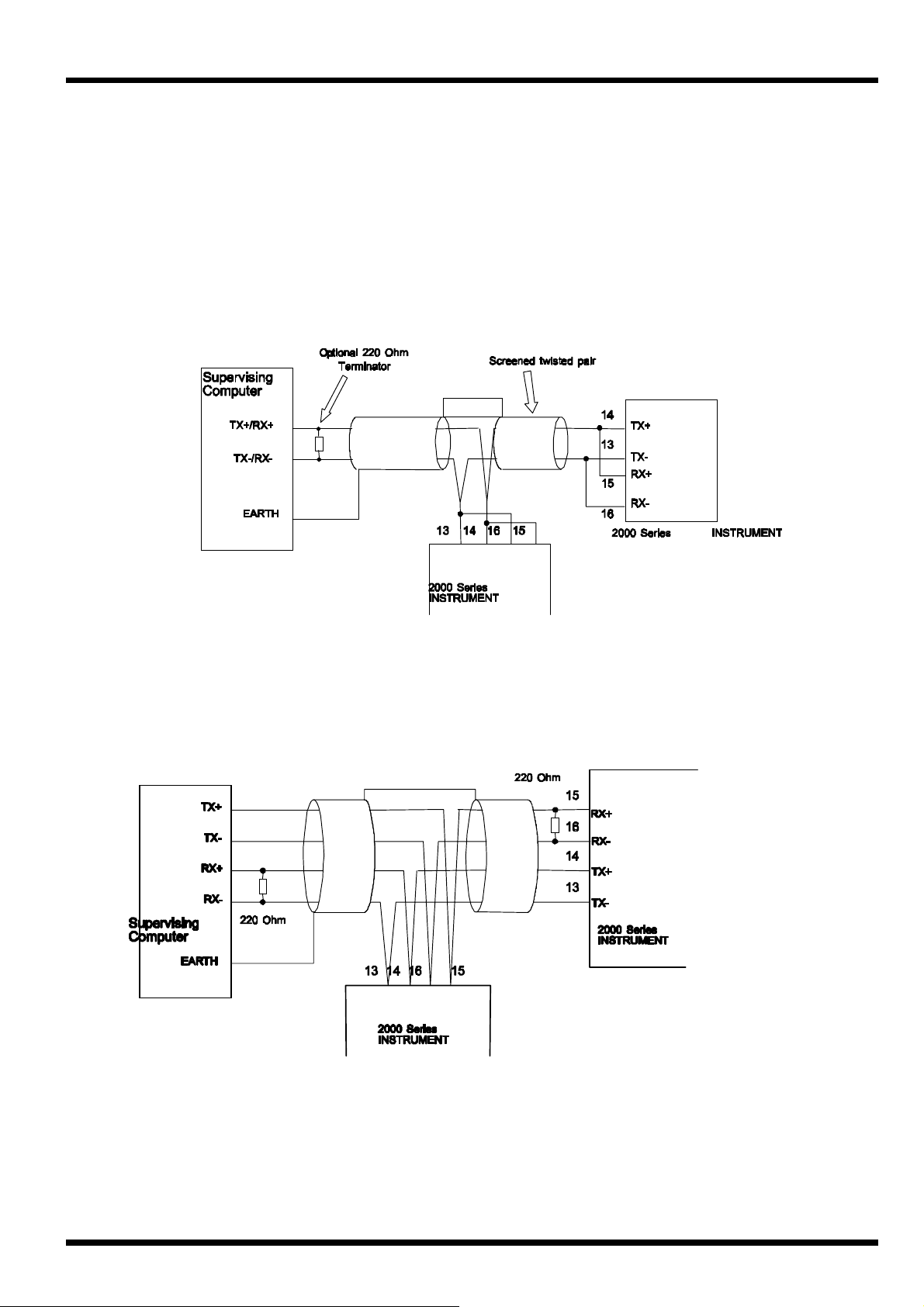
2.2 2 Wire EIA-485 Mode (RS-485)
This diagram shows the connection for EIA-485 mode. Note the use of screened cable. This
connection method may be continued on to other instruments up to the maximum allowed.
2.3 4-Wire EIA-422-A (RS-422)
This diagram shows the connection for EIA-422 mode. Note the use of screened cable.
This connection method may be continued on to other instruments up to the maximum
allowed.
M41 Issue 1.1
4 SERIES 2000 COMMUNICA TIONS M ANUA L
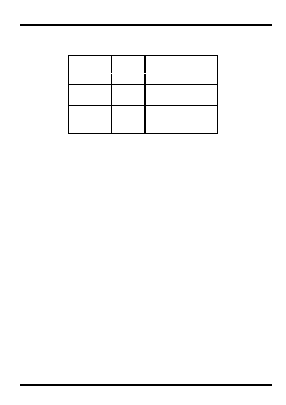
2.4 Connection reference table
Instrument
Terminal
13 TX- TX-/RX- TX-
14 TX+ TX+/RX+ TX+
15 RX+ TX+/RX+ RX+
16 RX- TX-/RX- RX-
1 EARTH N/C or
Function EIA-485 EIA-422-A
N/C or
SCREEN
SCREEN
2.5 Software Configuration.
Software configuration of the instrument may be performed once the instrument has been
placed in 'E mode'. This is done by removing the instrument from its sleeve and setting the
'E mode' switch to ON. The instrument is then replaced in its sleeve and power re-applied.
Use the scroll button (>) to scroll through elements until the
the star button to access the group.
ConS
group is reached. Press
Scroll to the element
9600 using the up/down keys
Scroll to the element
between 0 and 99 using the up/down keys. If the instrument is a P2000 programmer then
the controller part of the instrument will have an address as set by this parameter and the
programmer part of the instrument will have an address which is the controller address plus
16.
bAUd
AddrS
and select the baud rate required from 1200, 2400, 4800 or
. This is the controller instrument address and may be set
3.0 COMMUNICATIONS PROTOCOL
3.1 Message construction
Messages to and from the instrument vary in form depending on, amongst other things, the
type of message and its contents. There are three basic message types:-
3.1.1 Write messages
Write messages to the instrument take the following form.
WAAPSSD..D<CR>
where
M41 Issue 1.1
W
AA
P
SS
D..D
= write message header
= instrument address
= parameter code
= segment number field (P2000 Only)
= numeric data field

SERIES 2000 COMMUNICATIONS MANU AL 5
messages to the instrument may have the fields separated by spaces. These spaces will be
ignored. Messages from the instrument will not contain spaces. Eg.
W 45 C 0123 <CR>
will attempt to write 123 to the local set point as well as
W45C0123<CR>
The <CR> at the end of the message is a carriage return. (Hex 0D). Each message written
to the instrument must be terminated with, and each message from the instrument will be
terminated with a carriage return.
3.1.2 Read messages
Read messages to the instrument take the following form.
RAAPSS<CR>
where
Again the message must be terminated with a <CR>, and spaces may be included if
desired.
R
AA
P
SS
= read message header
= instrument address
= parameter code to be read
= segment number (P2000 Only)
3.1.3 Set instrument status messages
Set messages to the instrument take the following form.
SAAC<CR>
where
Again the message must be terminated with a <CR>, and spaces may be included if
desired.
S
AA
C
= set message header
= instrument address
= set parameter code to be performed
3.2 Message header.
This may be;
ASCII R signifying a Read
ASCII W signifying a Write
ASCII S signifying a Set.
The R header is used whenever data is being read from the instrument. When this header
is used the data field is absent. The W header is used to write data to the instrument. The
header is used to set the status of the instrument.
S
M41 Issue 1.1
 Loading...